EP4037584B1 - System zur fluideintrittskontrolle für ein hauttransplantationssystem - Google Patents
System zur fluideintrittskontrolle für ein hauttransplantationssystem Download PDFInfo
- Publication number
- EP4037584B1 EP4037584B1 EP20870755.4A EP20870755A EP4037584B1 EP 4037584 B1 EP4037584 B1 EP 4037584B1 EP 20870755 A EP20870755 A EP 20870755A EP 4037584 B1 EP4037584 B1 EP 4037584B1
- Authority
- EP
- European Patent Office
- Prior art keywords
- configurations
- cartridge
- housing
- tissue
- shield
- Prior art date
- Legal status (The legal status is an assumption and is not a legal conclusion. Google has not performed a legal analysis and makes no representation as to the accuracy of the status listed.)
- Active
Links
Images


Classifications
-
- A—HUMAN NECESSITIES
- A61—MEDICAL OR VETERINARY SCIENCE; HYGIENE
- A61B—DIAGNOSIS; SURGERY; IDENTIFICATION
- A61B17/00—Surgical instruments, devices or methods
- A61B17/32—Surgical cutting instruments
- A61B17/322—Skin grafting apparatus
-
- A—HUMAN NECESSITIES
- A61—MEDICAL OR VETERINARY SCIENCE; HYGIENE
- A61B—DIAGNOSIS; SURGERY; IDENTIFICATION
- A61B17/00—Surgical instruments, devices or methods
- A61B17/32—Surgical cutting instruments
- A61B17/3205—Excision instruments
-
- A—HUMAN NECESSITIES
- A61—MEDICAL OR VETERINARY SCIENCE; HYGIENE
- A61F—FILTERS IMPLANTABLE INTO BLOOD VESSELS; PROSTHESES; DEVICES PROVIDING PATENCY TO, OR PREVENTING COLLAPSING OF, TUBULAR STRUCTURES OF THE BODY, e.g. STENTS; ORTHOPAEDIC, NURSING OR CONTRACEPTIVE DEVICES; FOMENTATION; TREATMENT OR PROTECTION OF EYES OR EARS; BANDAGES, DRESSINGS OR ABSORBENT PADS; FIRST-AID KITS
- A61F2/00—Filters implantable into blood vessels; Prostheses, i.e. artificial substitutes or replacements for parts of the body; Appliances for connecting them with the body; Devices providing patency to, or preventing collapsing of, tubular structures of the body, e.g. stents
- A61F2/02—Prostheses implantable into the body
- A61F2/10—Hair or skin implants
- A61F2/105—Skin implants, e.g. artificial skin
-
- A—HUMAN NECESSITIES
- A61—MEDICAL OR VETERINARY SCIENCE; HYGIENE
- A61M—DEVICES FOR INTRODUCING MEDIA INTO, OR ONTO, THE BODY; DEVICES FOR TRANSDUCING BODY MEDIA OR FOR TAKING MEDIA FROM THE BODY; DEVICES FOR PRODUCING OR ENDING SLEEP OR STUPOR
- A61M37/00—Other apparatus for introducing media into the body; Percutany, i.e. introducing medicines into the body by diffusion through the skin
- A61M37/0015—Other apparatus for introducing media into the body; Percutany, i.e. introducing medicines into the body by diffusion through the skin by using microneedles
-
- A—HUMAN NECESSITIES
- A61—MEDICAL OR VETERINARY SCIENCE; HYGIENE
- A61B—DIAGNOSIS; SURGERY; IDENTIFICATION
- A61B17/00—Surgical instruments, devices or methods
- A61B2017/00831—Material properties
- A61B2017/00942—Material properties hydrophilic
-
- A—HUMAN NECESSITIES
- A61—MEDICAL OR VETERINARY SCIENCE; HYGIENE
- A61B—DIAGNOSIS; SURGERY; IDENTIFICATION
- A61B17/00—Surgical instruments, devices or methods
- A61B2017/00969—Surgical instruments, devices or methods used for transplantation
-
- A—HUMAN NECESSITIES
- A61—MEDICAL OR VETERINARY SCIENCE; HYGIENE
- A61B—DIAGNOSIS; SURGERY; IDENTIFICATION
- A61B17/00—Surgical instruments, devices or methods
- A61B17/32—Surgical cutting instruments
- A61B17/322—Skin grafting apparatus
- A61B2017/3225—Skin grafting apparatus with processing of harvested tissue
-
- A—HUMAN NECESSITIES
- A61—MEDICAL OR VETERINARY SCIENCE; HYGIENE
- A61B—DIAGNOSIS; SURGERY; IDENTIFICATION
- A61B90/00—Instruments, implements or accessories specially adapted for surgery or diagnosis and not covered by any of the groups A61B1/00 - A61B50/00, e.g. for luxation treatment or for protecting wound edges
- A61B90/08—Accessories or related features not otherwise provided for
- A61B2090/0813—Accessories designed for easy sterilising, i.e. re-usable
-
- A—HUMAN NECESSITIES
- A61—MEDICAL OR VETERINARY SCIENCE; HYGIENE
- A61M—DEVICES FOR INTRODUCING MEDIA INTO, OR ONTO, THE BODY; DEVICES FOR TRANSDUCING BODY MEDIA OR FOR TAKING MEDIA FROM THE BODY; DEVICES FOR PRODUCING OR ENDING SLEEP OR STUPOR
- A61M37/00—Other apparatus for introducing media into the body; Percutany, i.e. introducing medicines into the body by diffusion through the skin
- A61M37/0015—Other apparatus for introducing media into the body; Percutany, i.e. introducing medicines into the body by diffusion through the skin by using microneedles
- A61M2037/003—Other apparatus for introducing media into the body; Percutany, i.e. introducing medicines into the body by diffusion through the skin by using microneedles having a lumen
-
- A—HUMAN NECESSITIES
- A61—MEDICAL OR VETERINARY SCIENCE; HYGIENE
- A61M—DEVICES FOR INTRODUCING MEDIA INTO, OR ONTO, THE BODY; DEVICES FOR TRANSDUCING BODY MEDIA OR FOR TAKING MEDIA FROM THE BODY; DEVICES FOR PRODUCING OR ENDING SLEEP OR STUPOR
- A61M37/00—Other apparatus for introducing media into the body; Percutany, i.e. introducing medicines into the body by diffusion through the skin
- A61M37/0015—Other apparatus for introducing media into the body; Percutany, i.e. introducing medicines into the body by diffusion through the skin by using microneedles
- A61M2037/0061—Methods for using microneedles
-
- A—HUMAN NECESSITIES
- A61—MEDICAL OR VETERINARY SCIENCE; HYGIENE
- A61M—DEVICES FOR INTRODUCING MEDIA INTO, OR ONTO, THE BODY; DEVICES FOR TRANSDUCING BODY MEDIA OR FOR TAKING MEDIA FROM THE BODY; DEVICES FOR PRODUCING OR ENDING SLEEP OR STUPOR
- A61M2205/00—General characteristics of the apparatus
- A61M2205/12—General characteristics of the apparatus with interchangeable cassettes forming partially or totally the fluid circuit
Definitions
- the subject matter disclosed herein generally relates to a skin grafting system and, more particularly, to a system that may include a device for harvesting and scattering skin microcolumns.
- Skin grafting can be performed surgically.
- a conventional autograft procedure may include excision or surgical removal of burn injured tissue, choosing a donor site, which may be an area from which healthy skin is removed to be used as cover for the cleaned burned area, and harvesting, where the graft may be removed from the donor site (e.g., using an instrument similar to an electric shaver).
- Such instrument e.g., a dermatome
- Such instrument e.g., a dermatome
- the skin graft can then be placed over the cleaned wound to heal.
- Donor skin tissue can be removed to such a depth that the donor site can heal on its own, in a process similar to that of healing of a second degree burn.
- Sheet grafts can provide an improved appearance of the repaired tissue site.
- sheet grafts may be used on large areas of the face, neck and hands if they are damaged, so that these more visible parts of the body can appear less scarred after healing.
- a sheet graft may be used to cover an entire burned or damaged region of skin. Small areas of a sheet graft can be lost after placement because a buildup of fluid (e.g., a hematoma) can occur under the sheet graft following placement of the sheet graft.
- a buildup of fluid e.g., a hematoma
- skin tissue obtained from recently-deceased people (which may be referred to, e.g. as a homograft, an allograft, or cadaver skin) can be used as a temporary cover for a wound area that has been cleaned. Unmeshed cadaver skin can be put over the excised wound and stapled in place. Post-operatively, the cadaver skin may be covered with a dressing. Wound coverage using cadaveric allograft can then be removed prior to permanent autografting.
- a xenograft or heterograft can refer to skin taken from one of a variety of animals, for example, a pig.
- Heterograft skin tissue can also be used for temporary coverage of an excised wound prior to placement of a more permanent autograft, and may be used because of a limited availability and/or high expense of human skin tissue. In some cases religious, financial, or cultural objections to the use of human cadaver skin may also be factors leading to use of a heterograft.
- Wound coverage using a xenograft or an allograft is generally a temporary procedure which may be used until harvesting and placement of an autograft is feasible.
- Harvesting of the graft tissue from the donor site can generally generate undesirable large-scale tissue damage to the donor site.
- small areas of skin wounding adjacent to healthy tissue can be well-tolerated, and may heal quickly.
- Such healing of small wounds can occur in techniques such as "fractional photothermolysis” or "fractional resurfacing," in which patterns of damage having a small dimension can be created in skin tissue.
- These exemplary techniques are described, for example, in U.S. Patent No. 6,997,923 .
- Small-scale damage patterns can heal quickly by regrowth of healthy tissue, and can further provide desirable effects such as skin tightening without visible scarring.
- tissue grafting presents the opportunity for grafting tools to be exposed to clinical "soil” (e.g., blood, tissue, hair, etc.) from the patient.
- clinical "soil” e.g., blood, tissue, hair, etc.
- split-thickness and full-thickness skin grafting both of which harvest tissue that extends below the epidermis
- localized damage to capillaries and/or blood vessels often leads to bleeding.
- the degree of bleeding can be influenced by patient factors, such as, for example, anticoagulant medications.
- Document US 2019 / 008 542 A1 states in the abstract that the document "relates to a method for harvesting biological tissue"
- the document also states in the abstract that "the method includes providing a device having a plurality of segments of hollow tubes, each hollow tube having at least one point at the distal end of the hollow tube, the plurality of segments forming a two dimensional array of hollow tubes, wherein each segment can include a plurality of hollow tubes”.
- the document also discloses a grafting device having a tissue stabilizer and a disposable needle array containing needles for harvesting tissue.
- the present disclosure provides a skin grafting system having a handheld device, a cartridge, and a disposable device shield.
- the handheld device includes a device housing forming an interior that secures a drive system.
- the cartridge includes a plurality of hollow microneedles surrounded by a peripheral housing and is configured to be operated by the drive system to extend and retract past the peripheral housing into a subject to harvest tissue during a skin grafting process.
- the device shield is formed of a polymer extending from an interior opening to an exterior edge, the interior opening sized to extend about the peripheral housing to position the exterior edge over the device housing to inhibit ingress of fluids into the interior of the device housing from fluid about the peripheral housing of the cartridge during the skin grafting process performed using the skin grafting system.
- the present disclosure provides a skin grafting system having a handheld device, a cartridge, and a device shield.
- the handheld device includes a device housing having an engagement slot formed therein and creating an interior that secures a drive system.
- the cartridge is removably engaged with the handheld device through the engagement slot includes a plurality of hollow microneedles surrounded by a peripheral housing and configured to be operated by the drive system to extend and retract past the peripheral housing into a subject to harvest tissue during a skin grafting process.
- the device shield is formed of a flexible membrane extending from an interior opening to an exterior edge, the interior opening sized to extend about and be moved along the peripheral housing to form a barrier over the engagement slot when the exterior edge is arranged to extend over the device housing.
- connection means that one element/feature is directly or indirectly connected to another element/feature, and not necessarily electrically or mechanically.
- coupled means that one element/feature is directly or indirectly coupled to another element/feature, and not necessarily electrically or mechanically.
- Embodiments of the present disclosure may be described herein in terms of functional and/or logical block components and various processing steps. It should be appreciated that such block components may be realized by any number of hardware, software, and/or firmware components configured to perform the specified functions. For example, an embodiment may employ various integrated circuit components, e.g., digital signal processing elements, logic elements, diodes, etc., which may carry out a variety of functions under the control of one or more processors or other control devices. Other embodiments may employ program code, or code in combination with other circuit components.
- the present disclosure generally relates to a skin grafting system and, more particularly, to a system that may include a device for harvesting and scattering skin microcolumns.
- the process of harvesting the skin microcolumns can include penetrating donor site tissue. Although generally minimal, harvesting the microcolumns often causes localized bleeding. Blood quantity from the donor site can depend on a variety of factors, such as, for example, number of tissue punctures/penetrations, number of harvesting processes conducted on a single tissue area, number of harvesting processes conducted with a single cartridge (as described below), patient blood pressure, platelet count, medication, donor site treatments, and/or comorbidities. In some situations, it may be advantageous to prevent blood contact and/or ingress into portions of the skin grafting system. In particular, it may be advantageous to prevent blood ingress to reusable elements of the skin grafting system.
- the present disclosure includes systems for preventing blood ingress into a handheld device (e.g., a reusable handheld device) corresponding to a skin grafting system.
- a handheld device e.g., a reusable handheld device
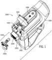
- the skin grafting system 3000 can be configured to harvest and scatter donor tissue.
- the skin grafting system 3000 can include a handheld device 1000 (which can be reusable) and a cartridge assembly 2000.
- the cartridge assembly 2000 can include a cartridge 2002 and a cartridge cover 2004.
- the cartridge 2002 can include a microneedle and pin array 2006, according to some configurations.
- the cartridge 2002 can include a simplified microneedle array 2006 (i.e., without pins).
- the handheld device 1000 can include an engagement slot 1002 configured to receive the cartridge assembly 2000.
- a loading door 1004 can move between an "open” position (see, e.g., FIG. 1 ) and a "closed” position (see, e.g., FIGS. 2A-2B ).
- the loading door 1004 can be hinged and further configured to open and close over a loading aperture 1006.
- the handheld device 1000 can include a door sensor, which can determine the position of the loading door 1004.
- the loading aperture 1006 can be sized such that the cartridge assembly 2000 can slide in and out of the engagement slot 1002, as desired by the user.
- the cartridge assembly 2000 can be single-use and/or disposable (including, for example, multiple uses for a single patient), while the handheld device 1000 can be designed to be multi-use.
- the handheld device 1000 can further include a trigger 1014.
- the trigger 1014 can be configured to activate a harvesting process and/or a scattering process in response to selection via a user interface 1008 and/or trigger inputs by a user.
- the handheld device 1000 can include an indicator light 1016.
- the indicator light 1016 can be positioned such that a user can readily view the indicator light 1016 during harvesting and/or scattering.
- the handheld device 1000 can include a user interface 1008.
- the user interface 1008 can include a stand-by input 1018, an indicator light 1020, and/or a scatter input 1022.
- the indicator light 1020 can operate the same as, or similar to, the indicator light 1016 (as described above).
- the stand-by input 1018, the indicator lights 1016,1020, and the scatter input 1022 can provide visual feedback to a user that correspond to current operation of the skin grafting system 3000 as the skin grafting system 3000 is utilized according to a skin grafting process, such as will be described.
- the handheld device 1000 is shown to include various internal controllers.
- the handheld device 1000 can include a power module 1028, a solenoid controller 1030, and/or a main controller 1032.
- the power module 1028 can be in electrical communication with a power input 1038.
- a drive system can include a solenoid in communication with the solenoid controller 1030.
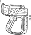
- the handheld device 1000 can include a housing 1036.
- the housing 1036 can include a left enclosure half and a right enclosure half.
- each of the left enclosure half, the right enclosure half, the loading door 1004 and the enclosure mount cover can be individually injection molded.
- the left and right enclosure halves can be made up of a hard plastic substrate, and in some configurations, a softer elastomeric over-molded section.
- the loading door 1004 and the enclosure mount cover can be made up of hard plastic substrate.
- the interior of the housing 1036 can interface with internal subassemblies.
- ribs can be affixed to the interior of the housing 1036, and can be configured to support various printed circuit boards (PCBs).
- the ribs can separate the PCBs (e.g., power module 1028, solenoid controller 1030, and main controller 1032) from internal moving components.
- the housing 1036 can support the internal subassembly 1034 via pins and vibration damping boots. This can dampen the operational impacts of the internal subassembly 1034 (e.g., from a user, from internal moving components), as well as protect the internal subassembly 1034 from damage due to external impacts (e.g., from dropping the handheld device 1000.
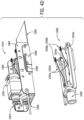
- FIG. 4A shows the internal subassembly 1034 that can include a left frame assembly 1040a, a right frame assembly 1040b, a horizontal component assembly 1044, and/or a vertical component assembly 1046.
- Each of the left and right frame assemblies 1040a, 1040b can include a corresponding flipper assembly (e.g., left flipper assembly 1048a, right flipper assembly 1048b).
- the horizontal component assembly 1044 can include a horizontal motor 1050.
- the vertical component assembly 1046 can include a solenoid 1052.
- the flag sensors 1060a, 1060b can communicate with a position sensing linear slide 1054, and a position sensing flag 1062.
- the left frame assembly 1040a can include position sensing springs 1056a, 1056b, which can contact a tissue interface 1058a.
- the tissue interface 1058a can be positioned on a third side of the left frame.
- the left frame assembly 1040a can attach to a portion of the vertical component assembly 1046 via screws and alignment pins, or other attachment systems.
- the right frame assembly 1040b can include flag sensors 1060c, 1060d, affixed to a first side of a right frame.
- the flag sensors 1060c, 1060d can communicate with a position sensing linear slide 1054, and a position sensing flag 1062.
- the right frame assembly 1040b can include a right flipper assembly 1048b affixed to a second side of the right frame.
- the right frame assembly 1040b can include position sensing springs 1056c, 1056d, which can contact a tissue interface 1058b.
- the tissue interface 1058b can be positioned on a third side of the right frame.
- the right frame assembly 1040b can attach to a portion of the vertical component assembly 1046 via screws and alignment pins.
- the flipper assemblies 1048a, 1048b can include a flipper mounting block 1066, and a flipper motor 1068.
- the flipper mounting block 1066 can be constructed from a dielectric material.
- the flipper motor 1068 can be connected to (and control) flipper driver pulleys 1070a, 1070b.
- a bearing (e.g., a thrust bearing) 1072 can support an axial load exerted by the needle top plate (e.g., needle top plate 1112 as described below) on a flipper 1074.
- the flipper 1074 can rotate in accordance with motor actuation, and the flipper driver pulleys 1070a, 1070b can prevent any downward movement of the flipper 1074 during operation of the handheld device 1000.
- the flipper 1074 can include two connected components, such as two brass components that are brazed together.
- the primary function of the flipper 1074 can be to hold a needle top plate 1112 of Fig. 4E in place when loading needle retract springs. The flipper 1074 can then move out of the way of the needle top plate 1112 during the remainder of normal operation.
- the flipper mounting block 1066 can act as a guide for solenoid plunger bar 1106 of Fig. 4E (e.g., to keep proper alignment).
- the horizontal component assembly can include sensors, actuators, and/or guides for positioning a horizontal carriage assembly 1082 and, thereby, the hammers 1098a, 1098b used to drive microneedles into the tissue (as will be described below).
- a horizontal flag sensor 1064 can be used to position the horizontal component assembly 1082.
- the horizontal component assembly 1044 can include the horizontal carriage assembly 1082 that can be configured to mount the horizontal motor 1050.
- a horizontal chassis 1084 can support the horizontal carriage assembly 1082.
- right frame assembly 1040b and the left frame assembly 1040a can be affixed to opposing sides of the horizontal chassis 1084, for example, using rivets.
- An earth-ground connection 1080 can be attached to the horizontal chassis 1084, according to some configurations.
- the horizontal component assembly 1044 can further include a retractable slide door 1090.
- the slide door 1090 can extend across the loading aperture 1006 when the cartridge 2002 has not been inserted into the engagement slot 1002. Accordingly, a user can be prevented from placing anything into the handheld device 1000 during the absence of the cartridge 2002.
- the sliding door 1090 can be secured to a sliding door mount 1086, which can be affixed to the horizontal chassis 1084. Additionally, a sliding door spring 1088 can be secured to the sliding door mount 1086, and biased such that the slide door 1090 remains in a "closed" position (i.e., extended across the loading aperture 1006) when a cartridge is not loaded.
- the horizontal carriage assembly 1082 can include hammers 1098a, 1098b, corresponding hammer return springs 1092a, 1092b, and corresponding hammer guides 1094a, 1094b, according to some configurations.
- the horizontal carriage assembly 1082 can be configured to position and guide the hammers 1098a, 1098b to drive the microneedles into the tissue.
- the hammer guides 1094a, 1094b can be made of bronze, which can help to maintain bearing surfaces throughout many harvesting and scattering cycles.
- the hammers 1098a, 1098b can be hardened 17-4 stainless steel, which can provide superior wear characteristics while maintaining anti-corrosion properties.
- the hammers 1098a, 1098b can be a different bearing material.
- the horizontal carriage assembly 1082 can further include a horizontal leadscrew drive nut 1096.
- the horizontal leadscrew assembly 1096 can be a Teflon-coated lead screw, and an Acetal drive nut designed to reduce friction.
- the horizontal leadscrew assembly 1096 can include other material types.
- the horizontal leadscrew assembly 1096 can provide a pitch adequate for positional resolution and linear force.
- the horizontal carriage assembly 1082 can additionally use motor stalling to sense whether or not a cartridge is loaded, or if there is a device jam.
- the vertical component assembly 1046 can include the solenoid 1052 and corresponding solenoid plunger bar 1106. Additionally, the vertical component assembly 1046 can include a vertical motor 1100, and associated unlock cams 1102a, 1102b and vertical leadscrews 1104a, 1104b. In some configurations, the vertical position of the vertical carriage subassembly 1108 can be controlled by traveling up and down on the vertical leadscrews 1104a, 1104b (e.g., using the vertical motor 1100). As will be described, vertical positioning can move each of the microneedles corresponding to the cartridge 2002.
- the vertical component assembly 1046 can be configured to interface with and manipulate the cartridge 2002 and its associated components during harvesting and/or scattering of tissue.
- the vertical motor 1100 can be sized to fit within the vertical component assembly 1046 while still providing the torque and speeds necessary for manipulating the microneedle positions.
- the solenoid 1052 can deliver an operating force to the hammers 1098a, 1098b during harvesting.
- the solenoid 1052 can be activated by a half wave of AC current, as one non-limiting example.
- the force delivered by the solenoid 1052 can increase sharply, towards the end of its stroke.
- the mass of the solenoid plunger bar 1106 and the solenoid plunger can be selected based on the energy needed to drive the microneedles into the tissue.
- a stop e.g., a brass stop
- the vertical component assembly 1046 can include a vertical carriage assembly 1108.
- the vertical carriage assembly 1108 can include a needle retract slide 1110 with a top plate 1112.
- opposite ends of the vertical carriage assembly 1108 can include needle retract slide-latches 1116a, 1116b with corresponding latch plates 1122a, 1122b.
- the latch plates 1122a, 1122b can define a maximum position of the needle retract slide 1110.
- needle retract springs 1120 can be integrated into the vertical carriage assembly 1108, such that efficient retraction of the microneedles can be achieved over the pins.
- the needle retract slide-latches 1116a, 1116b can be used to lock down the needle retract slide 1110 in preparation for harvesting.
- the vertical carriage assembly 1108 can also move both the needles and pins (e.g., pins within the microneedles) at the same time.
- the vertical carriage assembly 1108 can include a cartridge latch 1114, which can be configured to secure the cartridge 2002 upon insertion into the loading aperture 1006. Additionally, a vertical flag 1118 can be affixed to the exterior of the vertical carriage assembly 1108, according to some configurations.
- the needle retract slide 1110 can further include guideposts 1124a, 1124b, which can be configured to guide the needle retract slide 1110 during vertical movement.
- the needle retract slide 1110 can include lockdown latches 1126, which can be in contact with the guideposts 1124a, 1124b, and configured to engage and disengage the microneedles during operating of the handheld device 1000.
- the needle retract slide 1110 can be a spring loaded subassembly that serves at least two purposes.
- the slide 1110 can lock needle modules down (after being driven into the tissue).
- the slide 1110 can retract the needles.
- the needle retract slide 1110 is only capable of retracting the needles, and cannot move the needles forward.
- the lockdown latches 1126 may be only functional after the skin grafting system 3000 has gone through initialization. Further detail regarding the operation of the skin grafting system 3000 is provided below.
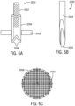
- the microneedle 2050 can facilitate harvesting of tissue from a donor site.
- the microneedle 2050 can include a hollow tube 2054 that can include a plurality of points 2056 at the distal end thereof.
- needle systems such as described in US Patent Nos. 9,060,803 ; 9,827,006 ; 9,895,162 ; and US Patent Application Publication Nos. 2015/0216545 ; 2016/0015416 ; 2018/0036029 ; 2018/0140316 and/or combinations or components thereof may be used.
- the hollow tube 2054 can be provided with two points 2056, and the points 2056 can be sufficiently angled for penetrating and cutting the biological tissue to remove small micrografts therefrom.
- a hollow tube 2054 can be provided with two points 2056, and a "narrow heel" portion positioned between the two points 2056.
- the narrow heel portion can be sharpened, such that a cutting edge corresponding to the hollow tube 2054 is created.
- the hollow tube 2054 can be slideably attached to a substrate 2058, such that the hollow tube 2054 can pass through a hole provided in the substrate 2058, as shown in FIG. 6A .
- the position of the hollow tube 2054 relative to the substrate 2058 can be controlled by translating the hollow tube 2054 relative to the substrate 2058, e.g., substantially along the longitudinal axis of the hollow tube 2054. In this manner, the distance that the distal end of the hollow tube 2054 protrudes past the lower surface of the substrate 2058 can be controllably varied.
- the microneedle 2050 can further include a pin 2052 provided in the central lumen or opening of the hollow tube 2054.
- the diameter of the pin 2052 can be substantially the same as the inner diameter of the hollow tube 2054 or slightly smaller, such that the hollow tube 2054 can be translated along an axis corresponding to pin 2052 while the pin 2052 fills or occludes most or all of the inner lumen of the hollow tube 2054.
- the pin 2052 can be formed of a low-friction material, or coated with a low-friction material such as, e.g., Teflon ® or the like, to facilitate motion of the hollow tube 2054 with respect to the pin 2052 and/or inhibit accumulation or sticking of biological material to the pin 2052.
- the distal end of the pin 2052 can be substantially flat to facilitate displacement of a tissue micrograft within the hollow tube 2054, when the hollow tube 2054 is translated relative to the pin 2052.
- the hollow tube 2054 can be translated relative to the pin 2052, e.g., substantially along the longitudinal axis of the hollow tube 2054. In this manner, the position of the distal end of the hollow tube 2054 relative to that of the distal end of the pin 2052 can be controllably varied. For example, the location of the distal ends of both the hollow tube 2054 and the pin 2052 relative to that of the lower surface of the substrate 2058 can be controllably and independently selected and varied.
- FIG. 6B shows one configuration of the present disclosure, in which the pin 2052 can be positioned relative to the hollow tube 2054 such that their distal ends are substantially aligned.
- the pin 2052 can extend slightly beyond the distal end of the hollow tube 2054, such that sharpened portions of the hollow tube 2054 can be shielded from undesired contact with objects and/or users.
- Portions of the pin 2052 and/or hollow tube 2054 can optionally be provided with a coating or surface treatment to reduce friction between them and/or between either component or biological tissue.
- a plurality of microneedles can form a microneedle array 2006.
- FIG. 6C shows a top view of an exemplary microneedle array 2006, according to configurations of the present disclosure.
- the microneedle array 2006 can be substantially circular.
- the microneedle array 2006 can be formed by assembling a plurality of rows of needles, either horizontal or vertical rows. This design can be modular, and the configuration can take on any shape or size using various size rows as modules.
- all of the microneedles can be actuated, e.g., inserted into the tissue, simultaneously. In other configurations, groups or sections can be actuated sequentially.
- the microneedle array 2006 can be divided into quadrants and each quadrant can be sequentially actuated. Sequentially can refer to actuating each row in a linear order, (e.g., row1, row2, row3), or non-linear (e.g. row1, row10, row3). Or, each row of microneedles can be separately and sequentially actuated. Additionally, each single microneedle can be separately and sequentially actuated. In some configurations, one row can be actuated at a time, e.g., 20 rows can be individually actuated in sequence, while in other configurations, two, three, four or more rows can be actuated at a time.
- microneedle array 2006 can be driven using a solenoid (e.g., solenoid 1052). Multiple actuations using the solenoid can sequence the insertion row by row.
- solenoid e.g., solenoid 1052
- the process 4000 can be implemented using the skin grafting system 3000, as described above.
- the process 4000 includes providing power to the handheld device (process block 4002).
- the handheld device can be the same or similar to handheld device 1000.
- the process 4000 is shown to further include loading a cartridge into the handheld device (process block 4004).
- the cartridge can be the same or similar to cartridge 2002, or cartridge assembly 2000.
- the process 4000 is shown to include activating a harvest mode (process block 4006).
- This activation can be initiated via user interface 1008, according to some configurations, such as will be described.
- the activation can be initiated via contact with a donor site.
- the process 4000 is shown to include applying a skin grafting system (e.g., skin grafting system 3000) to a donor site (process block 4008).
- the donor site can correspond to a healthy area of tissue on a patient.
- the process 4000 is shown to include initiating a harvesting process (process block 4010). In some configurations, this initiation can occur via the above-described trigger 1014.
- the process 4000 is shown to further include removing the skin grafting system from the donor site (process block 4012).
- the process 4000 is shown to include activating a scatter mode (process block 4014).
- the indicator light 1020 can produce steady white light when the handheld device 1000 is in harvest mode but sufficient pressure against a donor site has not been achieved, such as will be described during a skin grafting process. Further, the indicator light 1020 can produce steady green light when the handheld device 1000 is in harvest mode and sufficient pressure against the donor site has been achieved (and the trigger 1014 is disengaged). The indicator light 1020 can produce flashing green light when the handheld device 1000 is in the process of harvesting. If pressure drops below a threshold value during the harvesting process, the indicator light 1020 can produce flashing white light. Further, the indicator light 1020 can produce flashing white light when the handheld device 1000 is experiencing a fault condition.
- a plurality of operating positions corresponding to the skin grafting system 3000 can be defined.
- the skin grafting system 3000 can operate using additional operating positions not explicitly defined.
- Some configurations of the present disclosure include a harvest recovery mode, which can occur during the harvest process.
- the harvest recovery mode can include attempting to continue deploying the needle modules into the tissue. Additionally, the harvest recovery mode can be automatic and fully controlled by on-board software (i.e., no user interaction required).
- the harvest recovery mode can include reversing the motion of the horizontal carriage assembly 1082 by a predetermined distance or time interval. Subsequently, the horizontal carriage assembly 1082 can advance and again attempt to deploy the needle modules into the tissue.
- the vertical component assembly 1046 can have a predefined "loading" configuration that corresponds to loading of the cartridge 2002 into the handheld device 1000.
- the solenoid plunger bar 1106, each flipper 1074, and the needle retract slide 1110 can be retracted (the needles retracted).
- the vertical carriage assembly 1108 can be set to the home position (as described above).
- the vertical component assembly 1046 can have a predefined "initialization" configuration.
- each flipper 1074 can be extended (flipper out), and the needle retract slide 1110 can be locked with the needle retract springs 1120 loaded (the needles remain retracted).
- the vertical carriage assembly 1108 can be set to the lock position (see above). With each flipper 1074 extended, the vertical carriage assembly 1108 can move up to the lock position. The extended flippers 1074 can hold the needle retract slide 1110 in place.
- the needle retract slide latches 1116 can lock the top plate 1112 in place with the needle retract springs 1120 loaded. In some configurations, this does not move the needles from their retracted state.
- the vertical component assembly 1046 can have a predefined "initialized" configuration, which can correspond to the skin grafting system 3000 being ready to harvest.
- each flipper 1074 can be retracted (flipper in), and the needle retract slide 1110 can be locked with the needle retract springs 1120 loaded. In some configurations, this does not move the needles from their retracted state.
- the vertical carriage assembly 1108 can move back down to the home position, according to some configurations.
- the vertical component assembly 1046 can have a predefined "harvest" configuration corresponding to needle deployment.
- the solenoid plunger bar 1106 can advance, and the needle retract slide 1110 can remain locked with the needle retract springs 1120 loaded.
- the needles e.g., from microneedle array 2006
- the vertical carriage assembly 1108 can remain at the home position, and a user force can still be applied via the handheld device 1000, according to some configurations.
- the skin grafting assembly 3000 can begin the harvest sequence. Accordingly, the skin graft assembly 3000 can advance each microneedle array row of needles into the tissue by hitting the hammers 1098a, 1098b with the solenoid plunger bar 1106.
- the vertical component assembly 1046 can have a predefined "extraction" configuration.
- the solenoid plunger bar 1106 can be retracted, the needle retract slide 1110 can remain locked with the needle retract springs 1120 loaded.
- the needles (e.g., from microneedle array 2006) can remain deployed into the tissue at the start of extraction.
- the vertical carriage assembly 1108 can move to the extraction position (described above).
- the skin grafting system 3000 can extract the needles by lifting all of needles within the microneedle array 2006 at once. The needles can be lifted up to the extraction position, and the user force can be removed.
- the needles can remain advanced relative to the pins (e.g., pin 2052) and the tissue stabilizer 2014 can remain stationary when the needles are retracted.
- the vertical component assembly 1046 can have a "scatter" configuration corresponding to an advanced needle position.
- the solenoid plunger bar 1106 can advance, and the needle retract slide 1110 can advance (similarly, the needles can advance).
- the solenoid plunger bar 1106 can advance, first hitting the top plate 1112, and then hitting the needle modules (e.g., within microneedle array 2006). This can push the top plate 1112 ahead of needle carriers, thus preventing damage to the carriers.
- the advancing of the needles, followed by the rapid retraction of those needles can disperse the grafts into the recipient site.
- the vertical carriage assembly 1108 can move a very small amount upwards, such that the vertical flag 1118 clears the sensor. Subsequently, the vertical carriage assembly 1108 can return to the home position. In some configurations, the vertical carriage assembly 1108 can move up to the unlock position, where it can move the needle retract slide latches 1116, before returning to the home position. This can, for example, release the needle retract slide 1110, in the event that it is locked (e.g., cartridge 2002 is locked in).
- the horizontal carriage assembly 1082 can move to a predetermined position (e.g., approximately two-thirds of the way through its full range), which can verify that a cartridge (e.g., cartridge 2002) is not present. Subsequently, the horizontal carriage assembly 1082 can return to the home position.
- a predetermined position e.g., approximately two-thirds of the way through its full range
- the flippers 1074 can extend out and then retract back in. Further, in some configurations, some or all lights on handheld device 1000 can flash (e.g., indicator light 1016, 1020, scatter input 1022, etc.). Upon completion of the self-test, the stand-by input 1018 can light up solid green, for example, which can indicate that the self-test was successful.
- the skin grafting system 3000 can have a predefined cartridge loading and initialization process.
- the user can open the loading door 1004, then slide the cartridge assembly 2000 (i.e., including the cartridge cover 2004) into the engagement slot 1002.
- the cartridge latch 1114 can lock onto the cartridge 2002.
- the user can then remove the cartridge cover 2004 and close the loading door 1004, which can activate the internal loading door switch.
- the initialization process can further include moving the horizontal carriage assembly 1082 from the home position, such that it can detect the cartridge presence by stalling on the first cartridge segment. Subsequently, the horizontal carriage assembly 1082 can return to the home position. Additionally, the vertical carriage assembly 1108 can move a small amount, such that the vertical flag 1118 clears the sensor, and then the vertical carriage assembly 1108 can return to the home position.
- the flippers 1074 can extend out above the top plate 1112.
- the vertical carriage assembly 1108 can move to the lock position. While moving to the lock position, the flippers 1074 can hold the top plate 1112 in place while the needle retract slide latches 1116 move out, and eventually lock over the top plate 1112. Accordingly, the needle retract springs 1120 can be held in a compressed state. While this is happening, for example, the lockdown latches 1126 can spring out under the needle segments (e.g., within the microneedle array 2006), in preparation for locking the needle segments down during the harvest sequence. In some configurations, the vertical carriage assembly can then move a small amount down, thus moving into the lock relax position (described above). Additionally, the flippers 1074 can retract back in.
- the initialization process can further include returning the vertical carriage assembly 1108 to the harvest position.
- the horizontal carriage assembly 1082 can engage with the first needle segment (within microneedle array 2006) by stalling against the segment and subsequently backing off by a small predetermined distance.
- the handheld device 1000 can then calculate the position of each needle segment.
- the indicator light 1020 can illuminate white to indicate that the handheld device 1000 is ready for the harvest sequence.
- a user can harvest and extract tissue columns using a harvesting process.
- the user can position the handheld device 1000 at the donor site, with the tissue stabilizer 2014 pressed against the skin.
- the user can use one or two hands to apply force against the skin via the handheld device 1000.
- the tissue stabilizer interface components can move upward, compressing the position sensing springs 1056 until the position sensing flag 1062 occludes the flag sensor.
- the indicator lights 1016, 1020 can illuminate green, thus indicating that the trigger 1014 is active.
- the horizontal carriage assembly 1082 can return to the home position, according to some configurations.
- the vertical carriage assembly 1108 can move up to the extraction position, extracting the needles from the tissue, and positioning the needles safely up inside the tissue stabilizer 2014.
- the indicator lights 1016, 1020 can stop blinking green and turn off.
- the scatter input 1022 can be illuminated white, indicating that the handheld device 1000 is ready to proceed with the scattering process.
- the user can remove the force on the tissue, and lift the handheld device 1000 away.
- the process of rapidly advancing the solenoid plunger bar 1106 can be repeated several times, which can ensure that as many grafts as possible have been deposited into the recipient site. In some configurations, six activations of the solenoid 1052 can occur. After the scatter process has completed, the vertical carriage assembly 1108 can return to the home position, with the needle retract slide 1110 unlocked.
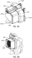
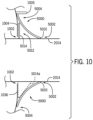
- the device shield 5000 can include corner cutouts (e.g., corner cutout 5006).
- corner cutout 5006 can be inverted and/or rounded, such that a user can easily grasp the device shield 5000 during application and removal from the skin grafting assembly 3000.
- the device shield 5000 can extend from an outer periphery of the tissue stabilizer 2014.
- the device shield 5000 inhibits blood flow onto and into the handheld device 1000, by, for example, protecting or sealing any openings corresponding to the engagement slot 1002 contact with the cartridge 2002, and the loading door 1004 contact with the cartridge 2002.
- the device shield 5000 can be formed of polymer that forms a barrier to fluids. Furthermore, the device shield 5000 may be formed of a pliable or an elastomeric material. The device shield 5000 may have a generally-flat geometry. By having a generally-flat geometry and being formed of a pliable or elastomeric material, the device shield opening 5002 can be dimensioned smaller than a perimeter dimension of the microneedle chamber 2018, such that the device shield 5000 can be stretched onto the microneedle chamber 2018. The stretching of the device shield 5000 can form a seal that is designed to be generally impenetrable to blood and other fluids impinging upon the device shield 5000, thus preventing fluid ingress into the handheld device 1000 along the tissue stabilizer 2014.
- the size of the device shield 5000 can vary, and in some embodiments, can be customized. As one example, the device shield 5000 can be cut to different shapes and sizes to customize the inhibition of blood ingress and usability of the skin grafting assembly 3000. According to some embodiments of the present disclosure, the device shield 5000 can be molded to a generally fixed shape and/or dimension. As one non-limiting example, the device shield 5000 can contact the exterior of the microneedle chamber 2018 (e.g., the tissue stabilizer 2014), and can otherwise extend outward therefrom (e.g., at a 90 degree angle, 45 degree angle, etc.). Accordingly, the device shield 5000 can provide a non-contact barrier for ingress points on the housing 1036.
- the microneedle chamber 2018 e.g., the tissue stabilizer 2014
Landscapes
- Health & Medical Sciences (AREA)
- Life Sciences & Earth Sciences (AREA)
- Surgery (AREA)
- Engineering & Computer Science (AREA)
- General Health & Medical Sciences (AREA)
- Public Health (AREA)
- Heart & Thoracic Surgery (AREA)
- Biomedical Technology (AREA)
- Veterinary Medicine (AREA)
- Animal Behavior & Ethology (AREA)
- Medical Informatics (AREA)
- Transplantation (AREA)
- Nuclear Medicine, Radiotherapy & Molecular Imaging (AREA)
- Molecular Biology (AREA)
- Plastic & Reconstructive Surgery (AREA)
- Dermatology (AREA)
- Anesthesiology (AREA)
- Hematology (AREA)
- Cardiology (AREA)
- Oral & Maxillofacial Surgery (AREA)
- Vascular Medicine (AREA)
- Surgical Instruments (AREA)
Claims (15)
- Hauttransplantationssystem (3000), umfassend:eine handgehaltene Vorrichtung (1000), die ein Vorrichtungsgehäuse (1036) umfasst, das einen Innenraum bildet, der ein Antriebssystem aufnimmt;eine Kartusche (2002), die mehrere hohle Mikronadeln (2006) umfasst, die von einem peripheren Gehäuse umgeben und dazu eingerichtet sind, durch das Antriebssystem betätigt zu werden, um sich über das periphere Gehäuse hinaus in einen Patienten zu erstrecken und zurückzuziehen, um während eines Hauttransplantationsprozesses Gewebe zu entnehmen; undeine Vorrichtungsabschirmung (5000), die aus einem Polymer gebildet ist und sich von einer inneren Öffnung zu einem äußeren Rand (5004) erstreckt, wobei die innere Öffnung so bemessen ist, dass sie sich um das periphere Gehäuse erstreckt, um den äußeren Rand (5004) über dem Vorrichtungsgehäuse zu positionieren, um zu verhindern, dass Fluide von Fluid um das periphere Gehäuse der Kartusche (2000) herum während des unter Verwendung des Hauttransplantationssystems (3000) durchgeführten Hauttransplantationsprozesses in das Innere des Vorrichtungsgehäuses eindringen.
- System (3000) nach Anspruch 1, wobei die Vorrichtungsabschirmung (5000) dazu eingerichtet ist, mit dem peripheren Gehäuse eine Barriere zu bilden.
- System (3000) nach Anspruch 2, wobei die Vorrichtungsabschirmung dazu eingerichtet ist, sich zu verformen, um sich über das periphere Gehäuse zu erstrecken, um mit dem peripheren Gehäuse die Barriere zu bilden.
- System (3000) nach Anspruch 1, wobei das Vorrichtungsgehäuse (1036) einen Eingriffnahmeschlitz (1002) bildet, um die Kartusche (1002) aufzunehmen, und wobei die Vorrichtungsabschirmung dazu eingerichtet ist, sich über den Eingriffnahmeschlitz (1002) zu erstrecken, um den äußeren Rand (5004) gegen das Vorrichtungsgehäuse (1036) anzuordnen, um eine Abschirmung dagegen zu bilden, dass Fluid den Eingriffnahmeschlitz (1002) erreicht.
- System (3000) nach Anspruch 4, wobei die Vorrichtungsabschirmung (3000) eine Tasche (5012) um den Eingriffnahmeschlitz (1002) herum bildet.
- System (3000) nach Anspruch 5, umfassend des Weiteren ein absorbierendes Material (5014), das in der Tasche (5012) angeordnet ist.
- System (3000) nach Anspruch 6, wobei das absorbierende Material (5014) dazu eingerichtet ist, das periphere Gehäuse zu umfangen.
- System (300) nach Anspruch 1, wobei die Vorrichtungsabschirmung (5000) aus einem elastomeren Material gebildet ist.
- Hauttransplantationssystem (3000), umfassend:eine handgehaltene Vorrichtung (1000), die ein Vorrichtungsgehäuse (1036) umfasst, in dem ein Eingriffnahmeschlitz (1002) ausgebildet ist und das einen Innenraum erzeugt, der ein Antriebssystem aufnimmt;eine Kartusche (2002), die durch den Eingriffnahmeschlitz (1002) abnehmbar mit der handgehaltenen Vorrichtung (1000) im Eingriff steht und mehrere hohle Mikronadeln (2006) aufweist, die von einem peripheren Gehäuse umgeben und dazu eingerichtet sind, durch das Antriebssystem betätigt zu werden, um sich über das periphere Gehäuse hinaus in einen Patienten zu erstrecken und zurückzuziehen, um während eines Hauttransplantationsprozesses Gewebe zu entnehmen; undeine Vorrichtungsabschirmung (5000), die von einer flexiblen Membran gebildet ist und sich von einer inneren Öffnung (5002) zu einem äußeren Rand (5004) erstreckt, wobei die innere Öffnung (5002) dafür bemessen ist, sich um das Umfangsgehäuse herum zu erstrecken und entlang des Umfangsgehäuses bewegt zu werden, um eine Barriere über dem Eingriffnahmeschlitz (1002) zu bilden, wenn der äußere Rand (5004) so angeordnet ist, dass er sich über das Vorrichtungsgehäuse erstreckt.
- System (3000) nach Anspruch 9, wobei die Vorrichtungsabschirmung (5000) eine Abdichtung mit dem peripheren Gehäuse bildet.
- System (3000) nach Anspruch 10, wobei sich die Vorrichtungsabschirmung (5000) so verformt, dass sie sich über das periphere Gehäuse erstreckt, um die Abdichtung mit dem peripheren Gehäuse zu bilden.
- System (3000) nach Anspruch 9, wobei die Vorrichtungsabschirmung eine Tasche (5012) um den Eingriffnahmeschlitz (1002) herum bildet.
- System (3000) nach Anspruch 12, das des Weiteren ein absorbierendes Material umfasst, das in der Tasche (1002) angeordnet ist.
- System (3000) nach Anspruch 13, wobei das absorbierende Material dazu eingerichtet ist, das periphere Gehäuse zu umfangen.
- System (3000) nach Anspruch 9, wobei die Vorrichtungsabschirmung (5000) aus einem Polymer gebildet ist, das für Flüssigkeiten undurchdringlich ist.
Priority Applications (1)
| Application Number | Priority Date | Filing Date | Title |
|---|---|---|---|
| EP25187836.9A EP4643818A2 (de) | 2019-10-03 | 2020-09-30 | System und verfahren zur flüssigkeitseintrittssteuerung für ein hauttransplantationssystem |
Applications Claiming Priority (2)
| Application Number | Priority Date | Filing Date | Title |
|---|---|---|---|
| US16/592,312 US11369409B2 (en) | 2019-10-03 | 2019-10-03 | System and method for fluid ingress control for a skin grafting system |
| PCT/US2020/053413 WO2021067363A1 (en) | 2019-10-03 | 2020-09-30 | System and method for fluid ingress control for a skin grafting system |
Related Child Applications (1)
| Application Number | Title | Priority Date | Filing Date |
|---|---|---|---|
| EP25187836.9A Division EP4643818A2 (de) | 2019-10-03 | 2020-09-30 | System und verfahren zur flüssigkeitseintrittssteuerung für ein hauttransplantationssystem |
Publications (3)
| Publication Number | Publication Date |
|---|---|
| EP4037584A1 EP4037584A1 (de) | 2022-08-10 |
| EP4037584A4 EP4037584A4 (de) | 2023-10-25 |
| EP4037584B1 true EP4037584B1 (de) | 2025-07-09 |
Family
ID=75273478
Family Applications (2)
| Application Number | Title | Priority Date | Filing Date |
|---|---|---|---|
| EP25187836.9A Pending EP4643818A2 (de) | 2019-10-03 | 2020-09-30 | System und verfahren zur flüssigkeitseintrittssteuerung für ein hauttransplantationssystem |
| EP20870755.4A Active EP4037584B1 (de) | 2019-10-03 | 2020-09-30 | System zur fluideintrittskontrolle für ein hauttransplantationssystem |
Family Applications Before (1)
| Application Number | Title | Priority Date | Filing Date |
|---|---|---|---|
| EP25187836.9A Pending EP4643818A2 (de) | 2019-10-03 | 2020-09-30 | System und verfahren zur flüssigkeitseintrittssteuerung für ein hauttransplantationssystem |
Country Status (6)
| Country | Link |
|---|---|
| US (3) | US11369409B2 (de) |
| EP (2) | EP4643818A2 (de) |
| CN (2) | CN115515514B (de) |
| AU (1) | AU2020357840A1 (de) |
| CA (1) | CA3174048A1 (de) |
| WO (1) | WO2021067363A1 (de) |
Families Citing this family (2)
| Publication number | Priority date | Publication date | Assignee | Title |
|---|---|---|---|---|
| US11369409B2 (en) | 2019-10-03 | 2022-06-28 | Medline Industries, Lp | System and method for fluid ingress control for a skin grafting system |
| US11633208B2 (en) | 2020-01-13 | 2023-04-25 | Medline Industries, Lp | System and method for clinical soil control for a skin grafting system |
Family Cites Families (27)
| Publication number | Priority date | Publication date | Assignee | Title |
|---|---|---|---|---|
| DE29919199U1 (de) | 1999-10-22 | 2000-01-20 | MediUm-TECH GmbH, 12681 Berlin | Tattoo- und/oder Permanent-Make-up-Farben-Handgerät |
| US6537242B1 (en) * | 2000-06-06 | 2003-03-25 | Becton, Dickinson And Company | Method and apparatus for enhancing penetration of a member for the intradermal sampling or administration of a substance |
| US6821281B2 (en) * | 2000-10-16 | 2004-11-23 | The Procter & Gamble Company | Microstructures for treating and conditioning skin |
| EP2289598A1 (de) | 2000-12-28 | 2011-03-02 | Palomar Medical Technologies, Inc. | Verfahren und Vorrichtung zur therapeutischen Behandlung der Haut |
| US7160326B2 (en) * | 2002-06-27 | 2007-01-09 | Depuy Products, Inc. | Method and apparatus for implantation of soft tissue implant |
| EP1633250A2 (de) | 2003-06-04 | 2006-03-15 | Georgia Tech Research Corporation | Vorrichtung zum bohren mit mikronadeln |
| CN101420991A (zh) * | 2003-11-20 | 2009-04-29 | 血管技术国际股份公司 | 聚合物组合物及其使用方法 |
| US8535299B2 (en) | 2004-01-23 | 2013-09-17 | Joseph Giovannoli | Method and apparatus for skin reduction |
| US7708724B2 (en) | 2004-04-05 | 2010-05-04 | Blue Sky Medical Group Incorporated | Reduced pressure wound cupping treatment system |
| US9125638B2 (en) | 2005-07-13 | 2015-09-08 | Boston Scientific Scimed, Inc. | Flexible biopsy collection device and related methods of use |
| KR101734469B1 (ko) | 2008-04-01 | 2017-05-11 | 더 제너럴 하스피탈 코포레이션 | 조직이식 장치 |
| KR101815035B1 (ko) | 2010-05-07 | 2018-01-08 | 더 제너럴 하스피탈 코포레이션 | 조직이식과 조직복제 장치 |
| JP5562138B2 (ja) * | 2010-06-24 | 2014-07-30 | シスメックス株式会社 | 微細孔形成装置 |
| US11109887B2 (en) | 2013-12-06 | 2021-09-07 | Srgi Holdings, Llc | Pixel array medical systems, devices and methods |
| WO2012145504A1 (en) * | 2011-04-20 | 2012-10-26 | Kci Licensing, Inc. | Skin graft devices and methods |
| AU2013302673B2 (en) | 2012-08-14 | 2017-12-21 | The General Hospital Corporation | Method and apparatus for tissue harvesting |
| CN110025881A (zh) * | 2012-09-13 | 2019-07-19 | 亚夫拉罕·阿米尔 | 用于皮肤改善的递送装置和方法 |
| EP3513833A1 (de) * | 2012-12-21 | 2019-07-24 | 3M Innovative Properties Co. | Klebstoffanordnungen und mikronadelinjektionsvorrichtungen damit |
| JP6494602B2 (ja) * | 2013-05-31 | 2019-04-03 | スリーエム イノベイティブ プロパティズ カンパニー | 二重カバーを備えるマイクロニードル注射装置 |
| CN105828731A (zh) * | 2013-10-02 | 2016-08-03 | Srgi控股有限责任公司 | 像素阵列式医疗设备及方法 |
| CA2955185C (en) | 2014-07-15 | 2023-01-10 | The General Hospital Corporation | Method and apparatus for tissue copying and grafting |
| GB2529390A (en) * | 2014-08-12 | 2016-02-24 | Owen Mumford Ltd | Needle assembly |
| US9743949B2 (en) * | 2015-04-22 | 2017-08-29 | Medline Industries, Inc. | Two-dimensional needle array device and method of use |
| KR20180084759A (ko) * | 2015-09-27 | 2018-07-25 | 폴리카 인코포레이티드 | 니들링 장치 및 약물 도포기 |
| US11051843B2 (en) | 2017-09-28 | 2021-07-06 | Bing Ma | Needle array guide for skin graft expansion apparatus, skin graft expansion apparatus and skin grafting system including the same, and related methods and components |
| US11193858B2 (en) * | 2018-05-01 | 2021-12-07 | Community Blood Center | Tissue planing assemblies and methods |
| US11369409B2 (en) | 2019-10-03 | 2022-06-28 | Medline Industries, Lp | System and method for fluid ingress control for a skin grafting system |
-
2019
- 2019-10-03 US US16/592,312 patent/US11369409B2/en active Active
-
2020
- 2020-09-30 CN CN202080083331.XA patent/CN115515514B/zh active Active
- 2020-09-30 EP EP25187836.9A patent/EP4643818A2/de active Pending
- 2020-09-30 WO PCT/US2020/053413 patent/WO2021067363A1/en not_active Ceased
- 2020-09-30 CN CN202510181841.5A patent/CN120036886A/zh active Pending
- 2020-09-30 EP EP20870755.4A patent/EP4037584B1/de active Active
- 2020-09-30 CA CA3174048A patent/CA3174048A1/en active Pending
- 2020-09-30 AU AU2020357840A patent/AU2020357840A1/en active Pending
-
2022
- 2022-05-26 US US17/825,431 patent/US12383300B2/en active Active
-
2025
- 2025-07-31 US US19/287,333 patent/US20250359891A1/en active Pending
Also Published As
| Publication number | Publication date |
|---|---|
| AU2020357840A1 (en) | 2022-05-12 |
| CN115515514A (zh) | 2022-12-23 |
| CA3174048A1 (en) | 2021-04-08 |
| CN115515514B (zh) | 2025-03-07 |
| US20220280180A1 (en) | 2022-09-08 |
| US11369409B2 (en) | 2022-06-28 |
| EP4037584A1 (de) | 2022-08-10 |
| US12383300B2 (en) | 2025-08-12 |
| EP4643818A2 (de) | 2025-11-05 |
| EP4037584A4 (de) | 2023-10-25 |
| WO2021067363A1 (en) | 2021-04-08 |
| US20210100572A1 (en) | 2021-04-08 |
| US20250359891A1 (en) | 2025-11-27 |
| CN120036886A (zh) | 2025-05-27 |
Similar Documents
| Publication | Publication Date | Title |
|---|---|---|
| US20250359891A1 (en) | System and Method for Fluid Ingress Control for a Skin Grafting System | |
| EP3405124B1 (de) | Minimal-invasive gewebeentnahmevorrichtung | |
| JP6215840B2 (ja) | 非傷跡発生式カニューレ | |
| BR112015018699B1 (pt) | Conjunto de atuador de extremidade para uso com um instrumento cirúrgico | |
| CN107735045A (zh) | 用于改进毛发移植的仪器、系统及方法 | |
| US20240032961A1 (en) | System and Method for Clinical Soil Control for a Skin Grafting System | |
| US20090024125A1 (en) | Automatically retracting needle-tip electrocautery device | |
| US20230414248A1 (en) | System and Method for Securing a Needle or Group of Needles Within a Skin Grafting System | |
| US8070764B2 (en) | Microkeratome with a detachable head | |
| US20230397928A1 (en) | Skin Core Micro-Coring System | |
| WO2025048725A1 (en) | A device for skin biopsy and scar revision | |
| OA18827A (en) | Minimally invasive tissue harvesting device. | |
| HK40001084A (en) | Minimally invasive tissue harvesting device | |
| HK40001084B (en) | Minimally invasive tissue harvesting device |
Legal Events
| Date | Code | Title | Description |
|---|---|---|---|
| STAA | Information on the status of an ep patent application or granted ep patent |
Free format text: STATUS: THE INTERNATIONAL PUBLICATION HAS BEEN MADE |
|
| PUAI | Public reference made under article 153(3) epc to a published international application that has entered the european phase |
Free format text: ORIGINAL CODE: 0009012 |
|
| STAA | Information on the status of an ep patent application or granted ep patent |
Free format text: STATUS: REQUEST FOR EXAMINATION WAS MADE |
|
| 17P | Request for examination filed |
Effective date: 20220503 |
|
| AK | Designated contracting states |
Kind code of ref document: A1 Designated state(s): AL AT BE BG CH CY CZ DE DK EE ES FI FR GB GR HR HU IE IS IT LI LT LU LV MC MK MT NL NO PL PT RO RS SE SI SK SM TR |
|
| DAV | Request for validation of the european patent (deleted) | ||
| DAX | Request for extension of the european patent (deleted) | ||
| A4 | Supplementary search report drawn up and despatched |
Effective date: 20230921 |
|
| RIC1 | Information provided on ipc code assigned before grant |
Ipc: A61M 37/00 20060101ALN20230915BHEP Ipc: A61B 90/00 20160101ALN20230915BHEP Ipc: A61F 2/10 20060101ALI20230915BHEP Ipc: A61B 17/3205 20060101ALI20230915BHEP Ipc: A61B 17/322 20060101AFI20230915BHEP |
|
| GRAP | Despatch of communication of intention to grant a patent |
Free format text: ORIGINAL CODE: EPIDOSNIGR1 |
|
| STAA | Information on the status of an ep patent application or granted ep patent |
Free format text: STATUS: GRANT OF PATENT IS INTENDED |
|
| RIC1 | Information provided on ipc code assigned before grant |
Ipc: A61M 37/00 20060101ALN20250121BHEP Ipc: A61B 90/00 20160101ALN20250121BHEP Ipc: A61F 2/10 20060101ALI20250121BHEP Ipc: A61B 17/3205 20060101ALI20250121BHEP Ipc: A61B 17/322 20060101AFI20250121BHEP |
|
| INTG | Intention to grant announced |
Effective date: 20250203 |
|
| RIC1 | Information provided on ipc code assigned before grant |
Ipc: A61M 37/00 20060101ALN20250127BHEP Ipc: A61B 90/00 20160101ALN20250127BHEP Ipc: A61F 2/10 20060101ALI20250127BHEP Ipc: A61B 17/3205 20060101ALI20250127BHEP Ipc: A61B 17/322 20060101AFI20250127BHEP |
|
| RIN1 | Information on inventor provided before grant (corrected) |
Inventor name: EVANS, THOMAS J. Inventor name: MCPHERSON, AARON Inventor name: GUILES, MARVIN A. |
|
| GRAS | Grant fee paid |
Free format text: ORIGINAL CODE: EPIDOSNIGR3 |
|
| GRAA | (expected) grant |
Free format text: ORIGINAL CODE: 0009210 |
|
| STAA | Information on the status of an ep patent application or granted ep patent |
Free format text: STATUS: THE PATENT HAS BEEN GRANTED |
|
| AK | Designated contracting states |
Kind code of ref document: B1 Designated state(s): AL AT BE BG CH CY CZ DE DK EE ES FI FR GB GR HR HU IE IS IT LI LT LU LV MC MK MT NL NO PL PT RO RS SE SI SK SM TR |
|
| REG | Reference to a national code |
Ref country code: GB Ref legal event code: FG4D |
|
| REG | Reference to a national code |
Ref country code: CH Ref legal event code: EP |
|
| REG | Reference to a national code |
Ref country code: IE Ref legal event code: FG4D |
|
| REG | Reference to a national code |
Ref country code: DE Ref legal event code: R096 Ref document number: 602020054360 Country of ref document: DE |
|
| P01 | Opt-out of the competence of the unified patent court (upc) registered |
Free format text: CASE NUMBER: UPC_APP_2639_4037584/2025 Effective date: 20250806 |
|
| REG | Reference to a national code |
Ref country code: NL Ref legal event code: FP |
|
| PGFP | Annual fee paid to national office [announced via postgrant information from national office to epo] |
Ref country code: DE Payment date: 20250929 Year of fee payment: 6 |
|
| PGFP | Annual fee paid to national office [announced via postgrant information from national office to epo] |
Ref country code: GB Payment date: 20250929 Year of fee payment: 6 |