EP3405124B1 - Minimal-invasive gewebeentnahmevorrichtung - Google Patents
Minimal-invasive gewebeentnahmevorrichtung Download PDFInfo
- Publication number
- EP3405124B1 EP3405124B1 EP17704105.0A EP17704105A EP3405124B1 EP 3405124 B1 EP3405124 B1 EP 3405124B1 EP 17704105 A EP17704105 A EP 17704105A EP 3405124 B1 EP3405124 B1 EP 3405124B1
- Authority
- EP
- European Patent Office
- Prior art keywords
- collection container
- harvesting device
- cutting tool
- minimally invasive
- tissue
- Prior art date
- Legal status (The legal status is an assumption and is not a legal conclusion. Google has not performed a legal analysis and makes no representation as to the accuracy of the status listed.)
- Active
Links
Images


Classifications
-
- A—HUMAN NECESSITIES
- A61—MEDICAL OR VETERINARY SCIENCE; HYGIENE
- A61B—DIAGNOSIS; SURGERY; IDENTIFICATION
- A61B17/00—Surgical instruments, devices or methods
- A61B17/32—Surgical cutting instruments
- A61B17/322—Skin grafting apparatus
-
- A—HUMAN NECESSITIES
- A61—MEDICAL OR VETERINARY SCIENCE; HYGIENE
- A61B—DIAGNOSIS; SURGERY; IDENTIFICATION
- A61B10/00—Instruments for taking body samples for diagnostic purposes; Other methods or instruments for diagnosis, e.g. for vaccination diagnosis, sex determination or ovulation-period determination; Throat striking implements
- A61B10/02—Instruments for taking cell samples or for biopsy
- A61B10/0233—Pointed or sharp biopsy instruments
-
- A—HUMAN NECESSITIES
- A61—MEDICAL OR VETERINARY SCIENCE; HYGIENE
- A61B—DIAGNOSIS; SURGERY; IDENTIFICATION
- A61B17/00—Surgical instruments, devices or methods
- A61B17/32—Surgical cutting instruments
- A61B17/320016—Endoscopic cutting instruments, e.g. arthroscopes, resectoscopes
- A61B17/32002—Endoscopic cutting instruments, e.g. arthroscopes, resectoscopes with continuously rotating, oscillating or reciprocating cutting instruments
-
- A—HUMAN NECESSITIES
- A61—MEDICAL OR VETERINARY SCIENCE; HYGIENE
- A61B—DIAGNOSIS; SURGERY; IDENTIFICATION
- A61B17/00—Surgical instruments, devices or methods
- A61B17/34—Trocars; Puncturing needles
- A61B17/3494—Trocars; Puncturing needles with safety means for protection against accidental cutting or pricking, e.g. limiting insertion depth, pressure sensors
-
- A—HUMAN NECESSITIES
- A61—MEDICAL OR VETERINARY SCIENCE; HYGIENE
- A61B—DIAGNOSIS; SURGERY; IDENTIFICATION
- A61B10/00—Instruments for taking body samples for diagnostic purposes; Other methods or instruments for diagnosis, e.g. for vaccination diagnosis, sex determination or ovulation-period determination; Throat striking implements
- A61B10/02—Instruments for taking cell samples or for biopsy
- A61B10/0233—Pointed or sharp biopsy instruments
- A61B10/0283—Pointed or sharp biopsy instruments with vacuum aspiration, e.g. caused by retractable plunger or by connected syringe
-
- A—HUMAN NECESSITIES
- A61—MEDICAL OR VETERINARY SCIENCE; HYGIENE
- A61B—DIAGNOSIS; SURGERY; IDENTIFICATION
- A61B10/00—Instruments for taking body samples for diagnostic purposes; Other methods or instruments for diagnosis, e.g. for vaccination diagnosis, sex determination or ovulation-period determination; Throat striking implements
- A61B10/02—Instruments for taking cell samples or for biopsy
- A61B2010/0225—Instruments for taking cell samples or for biopsy for taking multiple samples
-
- A—HUMAN NECESSITIES
- A61—MEDICAL OR VETERINARY SCIENCE; HYGIENE
- A61B—DIAGNOSIS; SURGERY; IDENTIFICATION
- A61B17/00—Surgical instruments, devices or methods
- A61B2017/0023—Surgical instruments, devices or methods disposable
-
- A—HUMAN NECESSITIES
- A61—MEDICAL OR VETERINARY SCIENCE; HYGIENE
- A61B—DIAGNOSIS; SURGERY; IDENTIFICATION
- A61B17/00—Surgical instruments, devices or methods
- A61B2017/00681—Aspects not otherwise provided for
- A61B2017/00734—Aspects not otherwise provided for battery operated
-
- A—HUMAN NECESSITIES
- A61—MEDICAL OR VETERINARY SCIENCE; HYGIENE
- A61B—DIAGNOSIS; SURGERY; IDENTIFICATION
- A61B17/00—Surgical instruments, devices or methods
- A61B2017/00743—Type of operation; Specification of treatment sites
- A61B2017/00747—Dermatology
- A61B2017/00761—Removing layer of skin tissue, e.g. wrinkles, scars or cancerous tissue
-
- A—HUMAN NECESSITIES
- A61—MEDICAL OR VETERINARY SCIENCE; HYGIENE
- A61B—DIAGNOSIS; SURGERY; IDENTIFICATION
- A61B17/00—Surgical instruments, devices or methods
- A61B2017/00969—Surgical instruments, devices or methods used for transplantation
-
- A—HUMAN NECESSITIES
- A61—MEDICAL OR VETERINARY SCIENCE; HYGIENE
- A61B—DIAGNOSIS; SURGERY; IDENTIFICATION
- A61B17/00—Surgical instruments, devices or methods
- A61B17/32—Surgical cutting instruments
- A61B2017/320064—Surgical cutting instruments with tissue or sample retaining means
-
- A—HUMAN NECESSITIES
- A61—MEDICAL OR VETERINARY SCIENCE; HYGIENE
- A61B—DIAGNOSIS; SURGERY; IDENTIFICATION
- A61B17/00—Surgical instruments, devices or methods
- A61B17/32—Surgical cutting instruments
- A61B17/322—Skin grafting apparatus
- A61B2017/3225—Skin grafting apparatus with processing of harvested tissue
Definitions
- the present invention relates generally to the field of tissue transplantation, and more specifically, to devices for replacing or regenerating soft tissue by autotransplantation (autograft), allotransplantation (allograft) or xenotransplantation (xenograft).
- autograft is a tissue transplant donated from the same individual, usually from another area of the body to heal injured tissue.
- An allograft is a tissue transplant from a genetically non-identical donor of the same species, whereas a xenograft is a tissue transplant from a different species.
- the apparatus of the present invention facilitates the collection of soft tissue fragments from one or more donor sites, e.g. for use in transplantation of micro grafts for wound treatment, such as deeper burns, pressure ulcers etc.
- the invention is not limited to use only in wound care and its related uses, but may be used to collect soft tissue fragments from any other site in a human or animal body for use in any other suitable area of the same or another human or animal body.
- the invention is described below in a non-limiting manner with reference to wound care applications for ease of description and understanding. Surgical or medical methods or procedures as such do not form part of the claimed invention.
- Skin tissue may be subject to many forms of damage, including burns, trauma, depigmentation and the like. Grafts are often used to repair damaged skin when the skin cannot promote self-healing. Indeed, today, skin grafting procedures have become an almost integral part of advanced wound care (e.g., treatment of diabetic ulcers, burns, pressure ulcers etc.). However, grafting techniques generally involve a large amount of tissue being removed from a donor site, preferably from the patient, and/or expensive and complex cultivation procedures using laboratory facilities to form larger portions of graft tissue from smaller donor samples.
- Sheet grafts can provide an improved appearance of the repaired tissue site and have been used.
- sheet grafts may be used on large areas of the face, neck and hands, so that these more visible parts of the body can appear less scarred after healing.
- a sheet graft may be used to cover an entire damaged region of skin, e.g., if the damaged site is small. Small areas of a sheet graft can be lost after placement because a build-up of fluid (e.g., a hematoma) can occur under the sheet graft following placement of the sheet graft.
- fluid e.g., a hematoma
- Sheet grafts may be full-thickness or split-thickness.
- a conventional split-thickness graft can be formed, e.g., by harvesting a sheet of epidermis and upper dermal tissue from a donor site, in a procedure similar to that of peeling an apple. The split-thickness graft can then be placed on the location of the burn or ulcer. The skin tissue may then grow back at the donor site following a generally extended healing time.
- Split-thickness grafts may be preferable to full-thickness grafts because removing large amounts of full-thickness skin tissue from the donor site can lead to scarring and extensive healing times at the donor site, as well as an increased risk of infection.
- skin tissue removed from the donor site for a split-thickness skin auto graft may include both the epidermis and a portion of the dermis, which can lead to some scarring and/or depigmentation (e.g., hyper-or hypo-pigmentation) at the donor site.
- a number of processing methods and strategies to increase the expansion rate are today present.
- a common method is called meshing, where the surgeon creates a number of small, non-connected cuts in the slice of tissue. The tissue can then be stretched until it has the appearance of a mesh or net. In this state, it can cover a larger area of a wound.
- Other methods of processing include cutting the tissue into particles with knives, blades, or scissors.
- Split thickness skin grafts are often expanded by means of even non-connected cuts in the tissue which allow for the tissue to be stretched in all directions resulting in an even "hole” pattern. This is done partly to allow for a larger wound to be covered and partly to allow for exudates to be removed from the wound instead of being collected under the graft which is a big risk factor for infections.
- the skin graft can be expanded to varying extent depending on the size of the wound and the amount of available donor sites.
- the holes that are formed in the mesh are usually healing with the formation of scar tissue which causes a "fish scale" pattern on the patient which is a big part of the problem of aesthetic outcome associated with skin grafting. Frequently the skin grafts fail and have to be removed, and new skin grafts need to be harvested further worsening the extent and aesthetical appearance of both the donor sites and engraftment sites.
- Cultured keratinocytes used for covering of wounds are frequently cultured either directly on tissue culture treated polystyrene plastic flasks or dishes, on coated flasks or dishes or in flasks that contain a layer of cells, frequently referred to as feeder cells or feeder layer cells, that have been treated to prevent them from dividing and only provide signals that promote the survival of the keratinocytes.
- Feeder layer cells are often of murine origin and compose an inherent risk in the form of transfer of pathogens.
- Cells cultured on tissue culture treated polystyrene are frequently reported to be devoid of their stem cell subsets as the tissue culture treated polystyrene is thought to stimulate the differentiation of the cells from stem cells or progenitor cells towards adult cells.
- culturing and expansion of cells is believed to enrich for rapid dividing cells that might have an increased risk of becoming cancerous cells. Indeed, reports have recently been published where patients treated with cultured keratinocytes have needed surgical removal of skin cancers a few years after the grafting of the cultured epithelial autografts.
- US 2010/0145360 discloses a system and method for transplantation of dermal tissue comprising a tissue particle harvester with a tissue cutting tool of a rotating drum, rotating shaft or end mill cutting type.
- a tissue particle harvester with a tissue cutting tool of a rotating drum, rotating shaft or end mill cutting type.
- this device creates considerable sized wounds at the donor site and also limits the depth at which tissue can be harvested.
- the commercially available product CelluTome TM was developed to make skin grafting easier without inflicting large wounds at the donor site, as disclosed e.g. in US 2012/0035599 and US 2014/0277454 .
- the main principle of the device is that the skin is sucked up through small holes in a plate that is placed on the skin. The suction is applied by means of a vacuum pump. The vacuum is applied for about 1 hour after which the skin parts protruding through the holes are cut off using an integrated blade and the excised skin pieces are subsequently transferred to an adhesive membrane. The membrane is transferred to the site of engraftment and the donor site is covered by a dressing.
- the main drawback with this method is the amount of time required and the size and site limitations of the donor tissue.
- JP 2014-113211 A discloses a soft tissue collection device for insertion through an endoscope working channel and attachable to a hand piece.
- JP 2009-207659 A and US 2004/210229 A1 disclose bone fragment collection devices which may be attached to hand pieces, in particular for use in dental implant procedures.
- a tissue harvesting device for removing and collecting soft tissue fragments (e.g. micro grafts) from a donor site.
- the device comprises a rotary cutting tool adapted to cut soft tissue and a collection container for collecting the soft tissue micro grafts produced by the cutting tool.
- the collection container has a central bore extending in a longitudinal direction and a distal opening.
- the cutting tool is arranged in the central bore of the collection container and adapted to pass through the distal opening and draw harvested soft tissue fragments into the collection container.
- tissue harvesting device of the present invention minimises the damage caused to the donor site, which reduces the healing time and minimises the creation of new wounds at the donor sites whilst reducing the time needed for the procedure as well as increasing the amount of harvested soft tissue micro grafts compared to known tissue grafting devices.
- the disclosed device is simple and inexpensive when compared to existing tissue grafting systems and it can be used in a clinical setting not requiring cell cultures, enzymes, or specialised laboratory facilities.
- the tissue harvesting device further comprises a housing accommodating the cutting tool and the collection container, wherein the collection container is axially movable with respect to the housing. Axial movement of the collection container with respect to the housing enables proximal displacement of the collection container with respect to the cutting tool, which ensures that the cutting tool can penetrate to the desired depth in the soft tissue to be harvested whilst the distal tip of the collection container will be pressed against and remain in contact with the tissue surface at the intended donor site. Thereby, the harvested soft tissue pieces will be drawn directly into the collection container instead of passing on the outside of the collection container.
- the collection container is axially movable in relation to the housing to enable the cutting tool to penetrate into the intended soft tissue while the collection container is in contact with the donor site. If applied to skin, when the device is pressed towards the skin the rotating cutting tool will sever and engage skin fragments to pass through the hollow distal opening into the collection container. Preferably, the cutting tool will be long enough to actively transfer the soft tissue fragments all the way into the collection container.
- the collected micro grafts can be removed from the collection container and used as micro grafts during the transplantation procedure, e.g. in a hydrogel mixture covered by a primary dressing such as Epiprotect ® .
- tissue harvesting device Any type of soft human or animal tissue may be harvested by the tissue harvesting device according to the present invention to be used as soft tissue micro grafts.
- soft tissue include, but are not limited to, epithelium (skin, mucosal membranes etc.), connective tissue, muscle tissue and nervous tissue.
- the tissue harvesting device may be operated substantially parallel or perpendicular to the tissue surface from which soft tissue is to be harvested, or any angle there between.
- the distal end of the collection container comprises a sharp tip in the shape of a hollow needle.
- the sharp tip enables the collection container to penetrate the tissue surface through a clean cut to minimise damage to the tissue surface (e.g. epithelium) and to the tissue above the intended target depth.
- the sharp tip can be of various length depending on the type of soft tissue and required penetration depth. If the soft tissue is skin, the collection container can be used to cut an opening in the epidermis while the cutting tool will work under the "needle", thus protecting soft tissue not intended to be harvested by the cutting tool, and therefore does not increase the wound surface area at the level of epidermis, minimising risk for scarring and infection,.
- the tissue harvesting device further comprises means for selectively fixating the collection container or the cutting tool in relation to one another.
- the penetration depth of the cutting tool can be controlled and maintained during the harvesting procedure to ensure that only soft tissue from the desired depth is harvested. This will also make it possible to specify a maximal depth, ensuring safety and graft sample quality.
- the collection container is removably attached to the housing.
- the housing comprises a frangible portion adapted to be broken in order to remove the collection container.
- the tissue harvesting device further comprises a grip connected to a piston arranged coaxially with the collection container and the cutting tool, wherein the piston is adapted to be displaced in a distal direction by longitudinal movement of the grip in relation to the housing and enter the collection container to displace harvested soft tissue fragments towards the distal end of the collection container.
- the distal end of the collection container comprises a frangible portion adapted to be broken by a distal tip of the piston to expose harvested soft tissue fragments.
- the collection container is cylindrical and equipped with standard syringe connections to enable flushing of the collection container.
- the collection container may comprise a cylindrical sleeve wherein the distal opening for the cutting tool is arranged in the centre.
- the syringe connections facilitate removal of the collected soft tissue grafts in that the cylindrical collection container can be flushed.
- the cutting tool is made of a material capable of cutting and severing soft human or animal tissue, e.g. rubber, plastic or silicon, but softer than hard tissue. This enables soft tissue harvesting in the vicinity of hard tissue in the body, such as bone or tooth enamel, without risking damage to the hard tissue.
- the cutting tool is a drill bit comprising spiral flutes adapted to move soft tissue fragments from the donor site into the interior of the collection container.
- the helical grooves of the spiral flutes work to push the soft tissue pieces proximally into the collection container.
- the tissue harvesting device comprises a vacuum source adapted to suck soft tissue fragments into the collection container.
- the vacuum source provides additional means to draw the harvested soft tissue pieces into the collection container.
- the tissue harvesting device comprises a plurality of cutting tools.
- the collection container comprises a plurality of openings for accommodating the plurality of cutting tools.
- the tissue harvesting device comprises a plurality of collection containers, each having a respective cutting tool arranged thereon or therein.
- the diameter of the cutting tool is between 0.5 mm and 5 mm. This diameter has been found to be optimal when considering the potential amount of harvested soft tissue compared to the effect and damage caused on the donor site.
- An object of the present invention is to provide a new device for less invasive soft tissue grafting which enables the operator to collect autologous soft tissue micro grafts ready for direct transplantation without further processing, in particular but not limited to, autologous skin grafting procedures such as when treating severe wounds.
- micro grafts can later be removed from the collection container to be used for soft tissue repair.
- the tissue harvesting device is a hand piece that the operator can use with one hand.
- An electrical motor supported by a battery drives the rotary movement and the device could be built for either single (disposable) or multiple uses (reusable).
- distal and distal refer to a position or direction (furthest) away from the operator when using the tissue harvesting device according to the present invention.
- proximal refers to a position or direction closest to or towards the operator when using the tissue harvesting device according to the present invention.
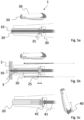
- a schematic cross-sectional view of a tissue harvesting device 1 is shown.
- the tissue harvesting device 1 comprises a cutting tool 10 adapted to cut and sever tissue, especially soft tissue as explained above.
- the tissue harvesting device 1 comprises a collection container 20 including a central bore 21 extending in a longitudinal direction and with a distal opening 22 provided at a distal end.
- the cutting tool is arranged in the central bore 21 of the collection container 20, preferably such that the axis of rotation of the cutting tool 10 substantially coincides with the central axis of the collection container 20.
- At least a distal tip or end 11 of the cutting tool 10 is adapted to pass through the distal opening 22 and draw harvested soft tissue proximally into the collection container 20 during the operation of soft tissue harvesting.
- the cutting tool 10 may be any suitable rotary tool adapted to cut and remove soft tissue from a donor site, such as e.g. a drill bit with spiral flutes, a milling cutter, a reamer, a burr or similar.
- the cutting tool 10 is chosen based on the specific type of soft tissue to be harvested, location of donor site, targeted penetration depth and/or desired graft size.
- the cutting tool 10 may be made of a soft and flexible material, i.e. softer than bone or dental tissue such as enamel and dentin, but harder than the soft tissue intended for harvesting. This enables soft tissue harvesting in the vicinity of hard tissue in the body without risking injury to the hard tissue.
- the cutting tool 10 preferably has a diameter of between 0.5 and 5 mm, to minimise wound surface area but harvest sufficient amounts of soft tissue micro grafts.
- the operator places the tissue harvesting device at the desired donor site, e.g. the outer layer of the skin, the epidermis 2.
- the rotary motion will allow the cutting tool 10 to penetrate the epidermis 2 and cut and remove soft tissue, e.g. in the form of skin fragments 3, from the donor site and transfer the harvested soft tissue fragments 3 proximally into the collection container 20.
- the cutting tool 10 may be a drill bit comprising helical or spiral flutes which pull the harvested soft tissue fragments 3 up along the shaft by the rotation of the drill bit.
- the tissue harvesting device 1 is further provided with or connectable to a power source (not shown) and comprises means for rotating the cutting tool 10 as known in the art, which will not be further discussed here.
- a tissue harvesting device 1 according to the present invention is shown.
- the tissue harvesting device 1 comprises a housing 30 in which the rotary cutting tool 10 is mounted with its axis of rotation being substantially parallel with the longitudinal extension of the housing 30. It is also foreseen within the scope of the present invention that the axis of rotation of the cutting tool 10 is arranged at an angle to the longitudinal extension of the housing 30, similar to e.g. a dentist drill.
- the housing 30 also accommodates the collection container 20, which may have the shape of a cylindrical tube or sleeve with a central bore. Other shapes of the collection container 20 are also contemplated as long as they are suitable for collecting soft tissue harvested by the cutting tool 10.
- the cutting tool 10 may comprise a centring disc 12 configured to ensure that the cutting tool 10 is centred within the central bore 21 of the collection container 20.
- the centring disc 12 may also serve to prevent harvested soft tissue fragments from passing towards the proximal end of the collection container 20.
- the collection container 20 is arranged to be axially movable with respect to the housing 30, e.g. by arranging the collection container 20 to be axially movable inside the housing 30 with the cutting tool 10 being fixed in relation to the housing 30. Additionally, the cutting tool 10 may be axially movable with respect to the housing 30 and the collection container 20.
- Fig. 2 shows the cutting tool 10 arranged substantially completely inside the collection container 20 in a first, retracted position, wherein the distal tip of the cutting tool 10 does not protrude through the distal opening 22 of the collection container 20.
- the collection container 20 and/or the cutting tool 10 may be biased towards the first position, e.g. by means of a resilient member such as a spring or similar as known in the art.
- Fig. 3 shows the tissue harvesting device 1 of Fig. 2 in operation.
- the operator has placed the tissue harvesting device 1 on the selected donor site and pressed the tissue harvesting device 1 against the outer layer of the skin, the epidermis 2.
- This causes the cutting tool 10 and housing 30 to move in a distal direction in relation to the collection container 20, as indicated by the downward arrows, such that the cutting tool 10 protrudes through the distal opening 22 of the collection container 20 and penetrates the skin.
- the collection container 20 remains pressed against the skin and is displaced in a proximal direction in relation to the housing 30 and the cutting tool 10, as indicated by the upward arrows.
- the cutting tool 10 will then cut and remove soft tissue from the donor site and transfer the harvested soft tissue proximally into the collection container 20.
- the cutting tool 10 may be a drill bit comprising helical flutes which pull the harvested soft tissue micro grafts 3 up along the shaft by the rotation of the drill bit. Because of the tight seal formed by the distal end of the collection container 20 pressed against the skin, the harvested soft tissue fragments 3 will not be spread out from the donor site outside the collection container 20. Instead, the harvested soft tissue fragments 3 will enter into the interior of the collection container 20.
- tissue harvesting device 1 may be used to harvest other types of soft tissue such as e.g. soft connective tissue, muscle tissue, nervous tissue, epithelial tissue, mucosal membranes etc. in any part of the body.
- the range of axial motion of the collection container 20 determines the depth of penetration of the cutting tool 10 into the soft tissue to be harvested.
- the outside surface of the collection container 20 may be provided with gradation markings to indicate the penetration depth to the operator. This facilitates harvesting soft tissue at the desired depth.
- the collection container 20 may be provided with an abutment member, e.g. in the shape of an exterior annular flange 23 arranged to abut against a distally facing portion of the housing 30, in order to limit axial movement in the proximal direction and thus, the penetration depth of the cutting tool 10.
- the tissue harvesting device 1 may be provided with means for selectively fixating the collection container 20 and/or the cutting tool 10 at a desired axial position with respect to the housing 30.
- Fig. 4 shows a further preferred embodiment of the tissue harvesting device 1 in a close-up view.
- the distal end of the collection container 20 comprises a sharp tip 24 in the shape of a hollow needle.
- the sharp tip 24 is adapted to easily penetrate the epidermis 2 at the donor site down to a desired depth, e.g. the dermis 4, and thereby act as a cannula or hollow needle for the cutting tool 10.
- the cutting tool 10 is moved distally through the sharp tip 24 without making contact with the epidermal tissue 2 above the desired penetration depth. This will cause only minimal damage to the epidermal tissue 2 above the intended target depth.
- the cutting tool 10 will protrude through the hollow needle and harvest the target dermis tissue 4, whereupon the harvested dermis tissue micro grafts 5 will be pulled proximally into the collection container 20 as explained above, whilst minimising the wound surface area at the level of epidermis 2, minimising risk for scarring and infection.
- the operator will ease the pressure on the collection container 20 in order to retract the cutting tool 10 through the distal opening 22.
- a syringe may be used to flush or withdraw the micro grafts.
- the collection container 20 may comprise standard syringe connections (not shown).
- the collection container 20 may instead be removably attached to the housing 30 and thus be detached when the harvesting procedure has been terminated.
- the housing 30 may comprise a frangible portion adapted to be broken off to allow access to the collection container 20.
- Figs. 5a-5c illustrate an alternative embodiment of a tissue harvesting device 1 according to the present invention, wherein removal of harvested tissue is further facilitated.
- the tissue harvesting device comprises a cutting tool 10 arranged in the central bore of a collection container 20 and both being accommodated in a housing 30.
- the collection container 20 is biased in a distal direction by means of a spring 25, thereby covering the distal tip of the cutting tool 10 in a retracted position.
- a spring 25 thereby covering the distal tip of the cutting tool 10 in a retracted position.
- other alternatives for biasing the collection container 20 are also foreseen as mentioned above.
- the tissue harvesting device 1 is pressed against the surface of the soft tissue to be harvested at the desired donor site as shown by the arrows.
- the force exerted by the operator on the housing 30 causes the spring 25 to be compressed and the collection container 20 to move in a proximal direction in relation to the housing 30 and the cutting tool 10, thus allowing the cutting tool 10 to penetrate into the tissue.
- Fig. 5c shows a mechanism for removing harvested tissue from the collection container 20.
- a handle or grip 40 which is connected to a piston 41 arranged coaxially with the collection container 20 and the cutting tool 10.
- the piston 41 is hollow and the cutting tool 10 is arranged in the central bore of the piston 41, as shown in hatched lines in Fig. 5c .
- the grip 40 may be rotated with respect to the housing 30 and then moved in a distal direction in relation to the housing 30, thus pushing the piston 41 in a distal direction to enter the collection container 20, as shown in weaker shade in Fig. 5c .
- the harvested tissue in the collection container 20 is displaced by the piston 41 in a distal direction and may thus exit through the distal opening 22 of the collection container 20.
- the diameter of the piston 41 is adapted to the inner diameter of the collection container 20 to achieve a close fit, thus ensuring that all of the harvested tissue is displaced by the piston 41.
- a hatch or frangible portion at the distal end of the collection chamber 20 is irreversibly opened or broken by the distal tip 42 of the piston 41 as it reaches its distal most position to facilitate removal of harvested tissue.
- the distal tip 42 may further be sharp to facilitate breaking of the frangible portion. This function also serves to visibly show that the tissue harvesting device 1 and the collection container 20 have been used and should therefore be disposed of.
Landscapes
- Health & Medical Sciences (AREA)
- Life Sciences & Earth Sciences (AREA)
- Surgery (AREA)
- Medical Informatics (AREA)
- Animal Behavior & Ethology (AREA)
- Engineering & Computer Science (AREA)
- Biomedical Technology (AREA)
- Heart & Thoracic Surgery (AREA)
- Veterinary Medicine (AREA)
- Molecular Biology (AREA)
- Public Health (AREA)
- General Health & Medical Sciences (AREA)
- Nuclear Medicine, Radiotherapy & Molecular Imaging (AREA)
- Orthopedic Medicine & Surgery (AREA)
- Plastic & Reconstructive Surgery (AREA)
- Transplantation (AREA)
- Pathology (AREA)
- Surgical Instruments (AREA)
- Prostheses (AREA)
Claims (17)
- Vorrichtung zur minimalinvasiven Gewebeentnahme (1) zur Entnahme von Weichgewebe von einer Spenderstelle, umfassend:- ein rotierendes Schneidewerkzeug (10),- einen Sammelbehälter (20), einschließlich einer zentralen Bohrung (21), die sich in einer Längsrichtung erstreckt, und mit einer distalen Öffnung (22), wobei das Schneidewerkzeug in der zentralen Bohrung des Sammelbehälters angeordnet ist und angepasst ist, durch die distale Öffnung hindurchzugehen und entnommene Weichgewebefragmente (3; 5) in den Sammelbehälter zu ziehen, und- ein Gehäuse (30), in dem das Schneidewerkzeug und der Sammelbehälter untergebracht sind, wobei der Sammelbehälter in Bezug auf das Gehäuse axial beweglich ist,dadurch gekennzeichnet, dass die Vorrichtung ein Handstück ist, das mit einer Hand benutzt werden kann und das einen batteriegestützten Elektromotor umfasst, um die Drehbewegung des Schneidewerkzeugs anzusteuern, und
dass der Durchmesser des Schneidewerkzeugs (10) zwischen 0,5 mm und 5 mm liegt, um die Beschädigung der Spenderstelle zu minimieren. - Vorrichtung zur minimalinvasiven Gewebeentnahme (1) nach Anspruch 1, wobei der Sammelbehälter (20) mittels eines elastischen Elements in eine erste, zurückgezogene Position vorgespannt ist, in der die distale Spitze (11) des Schneidewerkzeugs (10) nicht durch die distale Öffnung (22) des Sammelbehälters (20) ragt.
- Vorrichtung zur minimalinvasiven Gewebeentnahme nach Anspruch 1 oder 2, wobei das distale Ende des Sammelbehälters eine scharfe Spitze (24) in Form einer Hohlnadel umfasst.
- Vorrichtung zur minimalinvasiven Gewebeentnahme nach einem der vorstehenden Ansprüche, weiter umfassend Mittel zur selektiven Fixierung des Sammelbehälters oder des Schneidewerkzeugs in Bezug aufeinander und/oder in Bezug auf das Gehäuse.
- Vorrichtung zur minimalinvasiven Gewebeentnahme nach einem der vorstehenden Ansprüche, wobei der Sammelbehälter abnehmbar an dem Gehäuse befestigt ist.
- Vorrichtung zur minimalinvasiven Gewebeentnahme nach Anspruch 5, wobei das Gehäuse einen zerbrechlichen Abschnitt umfasst, der aufgebrochen werden kann, um den Sammelbehälter abzunehmen.
- Vorrichtung zur minimalinvasiven Gewebeentnahme nach einem der vorstehenden Ansprüche, weiter umfassend einen Griff (40), der mit einem Kolben (41) verbunden ist, der koaxial mit dem Sammelbehälter und dem Schneidewerkzeug angeordnet ist, wobei der Kolben angepasst ist, durch eine Längsbewegung des Griffs in Bezug auf das Gehäuse in eine distale Richtung verschoben zu werden und in den Sammelbehälter einzutreten, um entnommene Weichgewebefragmente in Richtung des distalen Endes des Sammelbehälters zu verschieben.
- Vorrichtung zur minimalinvasiven Gewebeentnahme nach Anspruch 7, wobei das distale Ende des Sammelbehälters einen zerbrechlichen Abschnitt umfasst, der durch eine distale Spitze (42) des Kolbens aufgebrochen werden kann, um entnommene Weichgewebefragmente freizulegen.
- Vorrichtung zur minimalinvasiven Gewebeentnahme nach einem der vorstehenden Ansprüche, wobei der Sammelbehälter zylindrisch ist und mit Standard-Spritzenanschlüssen ausgestattet ist, um das Spülen des Sammelbehälters zu ermöglichen.
- Vorrichtung zur minimalinvasiven Gewebeentnahme nach einem der vorstehenden Ansprüche, wobei das Schneidewerkzeug aus einem Material hergestellt ist, das weicher ist als Hartgewebe.
- Vorrichtung zur minimalinvasiven Gewebeentnahme (1) nach Anspruch 10, wobei das Schneidewerkzeug (10) aus Gummi, Kunststoff oder Silikon hergestellt ist.
- Vorrichtung zur minimalinvasiven Gewebeentnahme nach einem der vorstehenden Ansprüche, wobei das Schneidewerkzeug ein Bohrer ist, der Spiralnuten umfasst, die angepasst sind, Weichgewebefragmente von der Spenderstelle in das Innere des Sammelbehälters zu bewegen.
- Vorrichtung zur minimalinvasiven Gewebeentnahme nach einem der vorstehenden Ansprüche, weiter umfassend eine Vakuumquelle, die angepasst ist, Weichgewebefragmente in den Sammelbehälter zu saugen.
- Vorrichtung zur minimalinvasiven Gewebeentnahme nach einem der vorstehenden Ansprüche, umfassend eine Vielzahl von Schneidewerkzeugen.
- Vorrichtung zur minimalinvasiven Gewebeentnahme nach Anspruch 14, wobei der Sammelbehälter eine Vielzahl von Öffnungen zur Aufnahme der Vielzahl von Schneidewerkzeugen umfasst.
- Vorrichtung zur minimalinvasiven Gewebeentnahme nach Anspruch 14, umfassend eine Vielzahl von Sammelbehältern, in denen jeweils ein Schneidewerkzeug angeordnet ist.
- Vorrichtung zur minimalinvasiven Gewebeentnahme nach einem der vorstehenden Ansprüche, wobei die Vorrichtung zur Gewebeentnahme ein Einwegartikel ist.
Applications Claiming Priority (2)
| Application Number | Priority Date | Filing Date | Title |
|---|---|---|---|
| SE1650080A SE541418C2 (en) | 2016-01-22 | 2016-01-22 | Minimally invasive tissue harvesting device |
| PCT/SE2017/050061 WO2017127018A1 (en) | 2016-01-22 | 2017-01-23 | Minimally invasive tissue harvesting device |
Publications (3)
| Publication Number | Publication Date |
|---|---|
| EP3405124A1 EP3405124A1 (de) | 2018-11-28 |
| EP3405124C0 EP3405124C0 (de) | 2023-06-07 |
| EP3405124B1 true EP3405124B1 (de) | 2023-06-07 |
Family
ID=57995254
Family Applications (1)
| Application Number | Title | Priority Date | Filing Date |
|---|---|---|---|
| EP17704105.0A Active EP3405124B1 (de) | 2016-01-22 | 2017-01-23 | Minimal-invasive gewebeentnahmevorrichtung |
Country Status (11)
| Country | Link |
|---|---|
| US (1) | US10932813B2 (de) |
| EP (1) | EP3405124B1 (de) |
| JP (1) | JP6930983B2 (de) |
| KR (1) | KR20180102107A (de) |
| CN (1) | CN108697437B (de) |
| EA (1) | EA036840B1 (de) |
| IL (1) | IL260630B2 (de) |
| SA (1) | SA518392053B1 (de) |
| SE (1) | SE541418C2 (de) |
| WO (1) | WO2017127018A1 (de) |
| ZA (1) | ZA201805106B (de) |
Families Citing this family (22)
| Publication number | Priority date | Publication date | Assignee | Title |
|---|---|---|---|---|
| US8900181B2 (en) | 2009-12-18 | 2014-12-02 | Srgi Holdings, Llc | Skin treatment and drug delivery device |
| US11103275B2 (en) | 2010-12-17 | 2021-08-31 | Srgi Holdings, Llc | Pixel array medical systems, devices and methods |
| US10905865B2 (en) | 2010-12-17 | 2021-02-02 | Srgi Holdings, Llc | Systems, devices and methods for fractional resection, fractional skin grafting, fractional scar reduction and fractional tattoo removal |
| US11109887B2 (en) | 2013-12-06 | 2021-09-07 | Srgi Holdings, Llc | Pixel array medical systems, devices and methods |
| US11278309B2 (en) | 2010-12-17 | 2022-03-22 | Srgi Holdings, Llc | Pixel array medical systems, devices and methods |
| US10736653B2 (en) | 2013-12-06 | 2020-08-11 | Srgi Holdings, Llc | Pixel array medical systems, devices and methods |
| US10702684B2 (en) | 2010-12-17 | 2020-07-07 | Srgi Holdings, Llc | Systems, devices and methods for fractional resection, fractional skin grafting, fractional scar reduction and fractional tattoo removal |
| US11000310B2 (en) | 2010-12-17 | 2021-05-11 | Srgi Holdings, Llc | Pixel array medical systems, devices and methods |
| ES2827049T3 (es) | 2013-10-02 | 2021-05-19 | Srgi Holdings Llc | Dispositivos médicos de conjunto de píxeles |
| CN105828731A (zh) | 2013-10-02 | 2016-08-03 | Srgi控股有限责任公司 | 像素阵列式医疗设备及方法 |
| US11229452B2 (en) | 2013-12-06 | 2022-01-25 | Srgi Holdings, Llc | Pixel array medical systems, devices and methods |
| US11937846B2 (en) | 2013-12-06 | 2024-03-26 | Srgi Holdings Llc | Pixel array medical systems, devices and methods |
| WO2018148214A2 (en) | 2014-10-02 | 2018-08-16 | Srgi Holdings, Llc | Pixel array medical systems, devices and methods |
| WO2016127091A1 (en) | 2015-02-05 | 2016-08-11 | Srgi Holdings, Llc | Pixel array medical systems, devices and methods |
| US11490952B2 (en) | 2015-08-31 | 2022-11-08 | Srgi Holdings, Llc | Pixel array medical devices and methods |
| US11980389B2 (en) | 2015-08-31 | 2024-05-14 | Srgi Holdings Llc | Handed spiral slotted scalpet array |
| US11751904B2 (en) | 2015-08-31 | 2023-09-12 | Srgi Holdings, Llc | Pixel array medical systems, devices and methods |
| US11564706B2 (en) | 2019-10-28 | 2023-01-31 | Srgi Holdings, Llc | Pixel array medical systems, devices and methods |
| WO2018217479A2 (en) | 2017-05-11 | 2018-11-29 | Srgi Holdings, Llc | Systems, devices and methods for fractional resection, fractional skin grafting, fractional scar reduction and fractional tattoo removal |
| KR102427018B1 (ko) * | 2019-06-11 | 2022-07-29 | 재단법인 베스티안재단 | 피부치료제의 제조방법 및 이로부터 얻어지는 피부치료제 |
| CN113317850B (zh) * | 2021-05-14 | 2023-01-13 | 上海埃尔顿医疗器械有限公司 | 超声波活检针 |
| CN115444517B (zh) * | 2022-09-27 | 2024-07-05 | 唐列云 | 一种微粒皮移植装置 |
Family Cites Families (21)
| Publication number | Priority date | Publication date | Assignee | Title |
|---|---|---|---|---|
| JPH07507950A (ja) * | 1992-05-11 | 1995-09-07 | ボストン サイエンティフィック コーポレイション | 多針生検器具 |
| US5591187A (en) * | 1995-07-14 | 1997-01-07 | Dekel; Moshe | Laparoscopic tissue retrieval device and method |
| US6071284A (en) * | 1995-10-30 | 2000-06-06 | Biomedical Enterprises, Inc. | Materials collection system and uses thereof |
| US20040031770A1 (en) * | 1996-11-18 | 2004-02-19 | Gardner Technologies, Inc. | Systems, devices and methods for opening a bottle sealed with a stopper and for sealing a bottle |
| US6673023B2 (en) * | 2001-03-23 | 2004-01-06 | Stryker Puerto Rico Limited | Micro-invasive breast biopsy device |
| US20020138021A1 (en) * | 2001-03-23 | 2002-09-26 | Devonrex, Inc. | Micro-invasive tissue removal device |
| US20020138091A1 (en) * | 2001-03-23 | 2002-09-26 | Devonrex, Inc. | Micro-invasive nucleotomy device and method |
| US8043287B2 (en) * | 2002-03-05 | 2011-10-25 | Kimberly-Clark Inc. | Method of treating biological tissue |
| US7666134B2 (en) | 2002-09-28 | 2010-02-23 | Kci Licensing, Inc. | System and method for transplantation of dermal tissue |
| WO2004075764A1 (en) | 2003-02-27 | 2004-09-10 | Applied Tissue Technologies Llc | Method and apparatus for processing dermal tissue |
| US7033359B2 (en) * | 2003-04-21 | 2006-04-25 | Moshe Meller | Rotary apparatus for grafting and collecting bone |
| US20070287933A1 (en) * | 2006-06-08 | 2007-12-13 | Chris Phan | Tissue debulking device and method of using the same |
| CN201036560Y (zh) * | 2007-04-28 | 2008-03-19 | 侯慧芳 | 微创取骨设备 |
| JP4888255B2 (ja) * | 2007-06-29 | 2012-02-29 | 住友金属工業株式会社 | 熱延鋼板およびその製造方法 |
| JP2009207659A (ja) * | 2008-03-04 | 2009-09-17 | Platon Japan:Kk | 歯科用骨収集装置 |
| CN201578281U (zh) * | 2009-11-04 | 2010-09-15 | 王绪友 | 一种具有螺旋刀体结构医用穿刺针 |
| US8562626B2 (en) | 2010-08-06 | 2013-10-22 | MoMelan Technologies, Inc. | Devices for harvesting a skin graft |
| AU2013302673B2 (en) * | 2012-08-14 | 2017-12-21 | The General Hospital Corporation | Method and apparatus for tissue harvesting |
| JP6258210B2 (ja) * | 2012-09-27 | 2018-01-10 | テルモ株式会社 | 生検デバイス |
| JP6020908B2 (ja) * | 2012-12-06 | 2016-11-02 | 国立研究開発法人産業技術総合研究所 | 内視鏡用組織片採取装置 |
| EP2967627B1 (de) | 2013-03-14 | 2017-08-30 | KCI Licensing, Inc. | Saugfähige substrate zur entnahme von hauttransplantaten |
-
2016
- 2016-01-22 SE SE1650080A patent/SE541418C2/en unknown
-
2017
- 2017-01-23 JP JP2018538213A patent/JP6930983B2/ja active Active
- 2017-01-23 CN CN201780007354.0A patent/CN108697437B/zh active Active
- 2017-01-23 EP EP17704105.0A patent/EP3405124B1/de active Active
- 2017-01-23 WO PCT/SE2017/050061 patent/WO2017127018A1/en not_active Ceased
- 2017-01-23 EA EA201891535A patent/EA036840B1/ru not_active IP Right Cessation
- 2017-01-23 KR KR1020187021997A patent/KR20180102107A/ko not_active Ceased
-
2018
- 2018-07-17 IL IL260630A patent/IL260630B2/en unknown
- 2018-07-19 SA SA518392053A patent/SA518392053B1/ar unknown
- 2018-07-20 US US16/040,639 patent/US10932813B2/en active Active
- 2018-07-30 ZA ZA2018/05106A patent/ZA201805106B/en unknown
Also Published As
| Publication number | Publication date |
|---|---|
| CN108697437B (zh) | 2021-09-21 |
| KR20180102107A (ko) | 2018-09-14 |
| US20180325543A1 (en) | 2018-11-15 |
| SE1650080A1 (en) | 2017-07-23 |
| SA518392053B1 (ar) | 2022-05-12 |
| EA201891535A1 (ru) | 2018-12-28 |
| US10932813B2 (en) | 2021-03-02 |
| EP3405124A1 (de) | 2018-11-28 |
| SE541418C2 (en) | 2019-09-24 |
| IL260630A (en) | 2022-12-01 |
| EP3405124C0 (de) | 2023-06-07 |
| JP6930983B2 (ja) | 2021-09-01 |
| IL260630B2 (en) | 2023-04-01 |
| ZA201805106B (en) | 2019-06-26 |
| CN108697437A (zh) | 2018-10-23 |
| EA036840B1 (ru) | 2020-12-25 |
| WO2017127018A1 (en) | 2017-07-27 |
| JP2019503793A (ja) | 2019-02-14 |
Similar Documents
| Publication | Publication Date | Title |
|---|---|---|
| US10932813B2 (en) | Minimally invasive tissue harvesting device | |
| JP4739212B2 (ja) | 皮膚組織移植システム | |
| US8226664B2 (en) | Biological unit removal tools with movable retention member | |
| US8202279B2 (en) | Follicular extraction punch and method | |
| US8128639B2 (en) | Tools and methods for harvesting follicular units | |
| US20070213741A1 (en) | Follicular extraction punch and method | |
| US20050245952A1 (en) | Apparatus and method for dermal punch and follicular unit circumferential incision | |
| JP2005527311A (ja) | 骨髄にアクセスする装置および方法 | |
| WO2004096064A1 (en) | Apparatus and method for dermal punch and follicular unit circumferential incision | |
| EP3267908B1 (de) | Werkzeug zur neurombehandlung | |
| HK40001084B (en) | Minimally invasive tissue harvesting device | |
| HK40001084A (en) | Minimally invasive tissue harvesting device | |
| OA18827A (en) | Minimally invasive tissue harvesting device. | |
| SE1650588A1 (en) | Multi-layer dermatome | |
| CN119074156A (zh) | 微型医用多用处取皮植皮机 | |
| WO2011016075A1 (en) | Surgical set for cutting the gingiva of a patient during positioning of osseointegrated implants | |
| Izmailov et al. | Optimization of Methods and Hardware Upgrade in Dermatoplastic Surgery in Combination with the Use of Ximedon, a Nonspecific Stimulator of Reparative Regeneration | |
| US20190350610A1 (en) | Tissue harvesting devices and methods | |
| RU88262U1 (ru) | Дрель медицинская | |
| HK1095074B (en) | System for transplantation of dermal tissue |
Legal Events
| Date | Code | Title | Description |
|---|---|---|---|
| STAA | Information on the status of an ep patent application or granted ep patent |
Free format text: STATUS: UNKNOWN |
|
| STAA | Information on the status of an ep patent application or granted ep patent |
Free format text: STATUS: THE INTERNATIONAL PUBLICATION HAS BEEN MADE |
|
| PUAI | Public reference made under article 153(3) epc to a published international application that has entered the european phase |
Free format text: ORIGINAL CODE: 0009012 |
|
| STAA | Information on the status of an ep patent application or granted ep patent |
Free format text: STATUS: REQUEST FOR EXAMINATION WAS MADE |
|
| 17P | Request for examination filed |
Effective date: 20180820 |
|
| AK | Designated contracting states |
Kind code of ref document: A1 Designated state(s): AL AT BE BG CH CY CZ DE DK EE ES FI FR GB GR HR HU IE IS IT LI LT LU LV MC MK MT NL NO PL PT RO RS SE SI SK SM TR |
|
| AX | Request for extension of the european patent |
Extension state: BA ME |
|
| DAV | Request for validation of the european patent (deleted) | ||
| DAX | Request for extension of the european patent (deleted) | ||
| REG | Reference to a national code |
Ref country code: HK Ref legal event code: DE Ref document number: 40001084 Country of ref document: HK |
|
| GRAP | Despatch of communication of intention to grant a patent |
Free format text: ORIGINAL CODE: EPIDOSNIGR1 |
|
| STAA | Information on the status of an ep patent application or granted ep patent |
Free format text: STATUS: GRANT OF PATENT IS INTENDED |
|
| INTG | Intention to grant announced |
Effective date: 20220707 |
|
| GRAJ | Information related to disapproval of communication of intention to grant by the applicant or resumption of examination proceedings by the epo deleted |
Free format text: ORIGINAL CODE: EPIDOSDIGR1 |
|
| STAA | Information on the status of an ep patent application or granted ep patent |
Free format text: STATUS: REQUEST FOR EXAMINATION WAS MADE |
|
| GRAP | Despatch of communication of intention to grant a patent |
Free format text: ORIGINAL CODE: EPIDOSNIGR1 |
|
| STAA | Information on the status of an ep patent application or granted ep patent |
Free format text: STATUS: GRANT OF PATENT IS INTENDED |
|
| INTC | Intention to grant announced (deleted) | ||
| INTG | Intention to grant announced |
Effective date: 20221130 |
|
| GRAS | Grant fee paid |
Free format text: ORIGINAL CODE: EPIDOSNIGR3 |
|
| GRAA | (expected) grant |
Free format text: ORIGINAL CODE: 0009210 |
|
| STAA | Information on the status of an ep patent application or granted ep patent |
Free format text: STATUS: THE PATENT HAS BEEN GRANTED |
|
| AK | Designated contracting states |
Kind code of ref document: B1 Designated state(s): AL AT BE BG CH CY CZ DE DK EE ES FI FR GB GR HR HU IE IS IT LI LT LU LV MC MK MT NL NO PL PT RO RS SE SI SK SM TR |
|
| REG | Reference to a national code |
Ref country code: GB Ref legal event code: FG4D |
|
| REG | Reference to a national code |
Ref country code: CH Ref legal event code: EP Ref country code: AT Ref legal event code: REF Ref document number: 1572456 Country of ref document: AT Kind code of ref document: T Effective date: 20230615 |
|
| REG | Reference to a national code |
Ref country code: DE Ref legal event code: R096 Ref document number: 602017069446 Country of ref document: DE |
|
| U01 | Request for unitary effect filed |
Effective date: 20230630 |
|
| U07 | Unitary effect registered |
Designated state(s): AT BE BG DE DK EE FI FR IT LT LU LV MT NL PT SE SI Effective date: 20230707 |
|
| REG | Reference to a national code |
Ref country code: LT Ref legal event code: MG9D |
|
| PG25 | Lapsed in a contracting state [announced via postgrant information from national office to epo] |
Ref country code: NO Free format text: LAPSE BECAUSE OF FAILURE TO SUBMIT A TRANSLATION OF THE DESCRIPTION OR TO PAY THE FEE WITHIN THE PRESCRIBED TIME-LIMIT Effective date: 20230907 Ref country code: ES Free format text: LAPSE BECAUSE OF FAILURE TO SUBMIT A TRANSLATION OF THE DESCRIPTION OR TO PAY THE FEE WITHIN THE PRESCRIBED TIME-LIMIT Effective date: 20230607 |
|
| PG25 | Lapsed in a contracting state [announced via postgrant information from national office to epo] |
Ref country code: RS Free format text: LAPSE BECAUSE OF FAILURE TO SUBMIT A TRANSLATION OF THE DESCRIPTION OR TO PAY THE FEE WITHIN THE PRESCRIBED TIME-LIMIT Effective date: 20230607 Ref country code: HR Free format text: LAPSE BECAUSE OF FAILURE TO SUBMIT A TRANSLATION OF THE DESCRIPTION OR TO PAY THE FEE WITHIN THE PRESCRIBED TIME-LIMIT Effective date: 20230607 Ref country code: GR Free format text: LAPSE BECAUSE OF FAILURE TO SUBMIT A TRANSLATION OF THE DESCRIPTION OR TO PAY THE FEE WITHIN THE PRESCRIBED TIME-LIMIT Effective date: 20230908 |
|
| PG25 | Lapsed in a contracting state [announced via postgrant information from national office to epo] |
Ref country code: SK Free format text: LAPSE BECAUSE OF FAILURE TO SUBMIT A TRANSLATION OF THE DESCRIPTION OR TO PAY THE FEE WITHIN THE PRESCRIBED TIME-LIMIT Effective date: 20230607 |
|
| PG25 | Lapsed in a contracting state [announced via postgrant information from national office to epo] |
Ref country code: IS Free format text: LAPSE BECAUSE OF FAILURE TO SUBMIT A TRANSLATION OF THE DESCRIPTION OR TO PAY THE FEE WITHIN THE PRESCRIBED TIME-LIMIT Effective date: 20231007 |
|
| PG25 | Lapsed in a contracting state [announced via postgrant information from national office to epo] |
Ref country code: SM Free format text: LAPSE BECAUSE OF FAILURE TO SUBMIT A TRANSLATION OF THE DESCRIPTION OR TO PAY THE FEE WITHIN THE PRESCRIBED TIME-LIMIT Effective date: 20230607 Ref country code: SK Free format text: LAPSE BECAUSE OF FAILURE TO SUBMIT A TRANSLATION OF THE DESCRIPTION OR TO PAY THE FEE WITHIN THE PRESCRIBED TIME-LIMIT Effective date: 20230607 Ref country code: RO Free format text: LAPSE BECAUSE OF FAILURE TO SUBMIT A TRANSLATION OF THE DESCRIPTION OR TO PAY THE FEE WITHIN THE PRESCRIBED TIME-LIMIT Effective date: 20230607 Ref country code: IS Free format text: LAPSE BECAUSE OF FAILURE TO SUBMIT A TRANSLATION OF THE DESCRIPTION OR TO PAY THE FEE WITHIN THE PRESCRIBED TIME-LIMIT Effective date: 20231007 Ref country code: CZ Free format text: LAPSE BECAUSE OF FAILURE TO SUBMIT A TRANSLATION OF THE DESCRIPTION OR TO PAY THE FEE WITHIN THE PRESCRIBED TIME-LIMIT Effective date: 20230607 |
|
| U20 | Renewal fee for the european patent with unitary effect paid |
Year of fee payment: 8 Effective date: 20240117 |
|
| PG25 | Lapsed in a contracting state [announced via postgrant information from national office to epo] |
Ref country code: PL Free format text: LAPSE BECAUSE OF FAILURE TO SUBMIT A TRANSLATION OF THE DESCRIPTION OR TO PAY THE FEE WITHIN THE PRESCRIBED TIME-LIMIT Effective date: 20230607 |
|
| REG | Reference to a national code |
Ref country code: DE Ref legal event code: R097 Ref document number: 602017069446 Country of ref document: DE |
|
| PLBE | No opposition filed within time limit |
Free format text: ORIGINAL CODE: 0009261 |
|
| STAA | Information on the status of an ep patent application or granted ep patent |
Free format text: STATUS: NO OPPOSITION FILED WITHIN TIME LIMIT |
|
| 26N | No opposition filed |
Effective date: 20240308 |
|
| PG25 | Lapsed in a contracting state [announced via postgrant information from national office to epo] |
Ref country code: MC Free format text: LAPSE BECAUSE OF FAILURE TO SUBMIT A TRANSLATION OF THE DESCRIPTION OR TO PAY THE FEE WITHIN THE PRESCRIBED TIME-LIMIT Effective date: 20230607 |
|
| PG25 | Lapsed in a contracting state [announced via postgrant information from national office to epo] |
Ref country code: MC Free format text: LAPSE BECAUSE OF FAILURE TO SUBMIT A TRANSLATION OF THE DESCRIPTION OR TO PAY THE FEE WITHIN THE PRESCRIBED TIME-LIMIT Effective date: 20230607 |
|
| REG | Reference to a national code |
Ref country code: CH Ref legal event code: PL |
|
| PG25 | Lapsed in a contracting state [announced via postgrant information from national office to epo] |
Ref country code: CH Free format text: LAPSE BECAUSE OF NON-PAYMENT OF DUE FEES Effective date: 20240131 |
|
| PG25 | Lapsed in a contracting state [announced via postgrant information from national office to epo] |
Ref country code: CH Free format text: LAPSE BECAUSE OF NON-PAYMENT OF DUE FEES Effective date: 20240131 |
|
| PG25 | Lapsed in a contracting state [announced via postgrant information from national office to epo] |
Ref country code: IE Free format text: LAPSE BECAUSE OF NON-PAYMENT OF DUE FEES Effective date: 20240123 |
|
| PG25 | Lapsed in a contracting state [announced via postgrant information from national office to epo] |
Ref country code: IE Free format text: LAPSE BECAUSE OF NON-PAYMENT OF DUE FEES Effective date: 20240123 |
|
| U20 | Renewal fee for the european patent with unitary effect paid |
Year of fee payment: 9 Effective date: 20250115 |
|
| PGFP | Annual fee paid to national office [announced via postgrant information from national office to epo] |
Ref country code: GB Payment date: 20250121 Year of fee payment: 9 |
|
| PG25 | Lapsed in a contracting state [announced via postgrant information from national office to epo] |
Ref country code: CY Free format text: LAPSE BECAUSE OF FAILURE TO SUBMIT A TRANSLATION OF THE DESCRIPTION OR TO PAY THE FEE WITHIN THE PRESCRIBED TIME-LIMIT; INVALID AB INITIO Effective date: 20170123 |
|
| PG25 | Lapsed in a contracting state [announced via postgrant information from national office to epo] |
Ref country code: HU Free format text: LAPSE BECAUSE OF FAILURE TO SUBMIT A TRANSLATION OF THE DESCRIPTION OR TO PAY THE FEE WITHIN THE PRESCRIBED TIME-LIMIT; INVALID AB INITIO Effective date: 20170123 |