EP4037286B1 - Verfahren und vorrichtung zur vorhersage eines fehlers eines optischen moduls - Google Patents
Verfahren und vorrichtung zur vorhersage eines fehlers eines optischen moduls Download PDFInfo
- Publication number
- EP4037286B1 EP4037286B1 EP21214867.0A EP21214867A EP4037286B1 EP 4037286 B1 EP4037286 B1 EP 4037286B1 EP 21214867 A EP21214867 A EP 21214867A EP 4037286 B1 EP4037286 B1 EP 4037286B1
- Authority
- EP
- European Patent Office
- Prior art keywords
- classification
- sample
- optical module
- sequence
- fault
- Prior art date
- Legal status (The legal status is an assumption and is not a legal conclusion. Google has not performed a legal analysis and makes no representation as to the accuracy of the status listed.)
- Active
Links
Images



Classifications
-
- G—PHYSICS
- G06—COMPUTING OR CALCULATING; COUNTING
- G06F—ELECTRIC DIGITAL DATA PROCESSING
- G06F18/00—Pattern recognition
- G06F18/20—Analysing
- G06F18/24—Classification techniques
- G06F18/241—Classification techniques relating to the classification model, e.g. parametric or non-parametric approaches
- G06F18/2415—Classification techniques relating to the classification model, e.g. parametric or non-parametric approaches based on parametric or probabilistic models, e.g. based on likelihood ratio or false acceptance rate versus a false rejection rate
-
- H—ELECTRICITY
- H04—ELECTRIC COMMUNICATION TECHNIQUE
- H04L—TRANSMISSION OF DIGITAL INFORMATION, e.g. TELEGRAPHIC COMMUNICATION
- H04L43/00—Arrangements for monitoring or testing data switching networks
- H04L43/16—Threshold monitoring
-
- H—ELECTRICITY
- H04—ELECTRIC COMMUNICATION TECHNIQUE
- H04B—TRANSMISSION
- H04B10/00—Transmission systems employing electromagnetic waves other than radio-waves, e.g. infrared, visible or ultraviolet light, or employing corpuscular radiation, e.g. quantum communication
- H04B10/07—Arrangements for monitoring or testing transmission systems; Arrangements for fault measurement of transmission systems
- H04B10/075—Arrangements for monitoring or testing transmission systems; Arrangements for fault measurement of transmission systems using an in-service signal
- H04B10/079—Arrangements for monitoring or testing transmission systems; Arrangements for fault measurement of transmission systems using an in-service signal using measurements of the data signal
- H04B10/0791—Fault location on the transmission path
-
- H—ELECTRICITY
- H04—ELECTRIC COMMUNICATION TECHNIQUE
- H04B—TRANSMISSION
- H04B10/00—Transmission systems employing electromagnetic waves other than radio-waves, e.g. infrared, visible or ultraviolet light, or employing corpuscular radiation, e.g. quantum communication
- H04B10/25—Arrangements specific to fibre transmission
-
- H—ELECTRICITY
- H04—ELECTRIC COMMUNICATION TECHNIQUE
- H04L—TRANSMISSION OF DIGITAL INFORMATION, e.g. TELEGRAPHIC COMMUNICATION
- H04L41/00—Arrangements for maintenance, administration or management of data switching networks, e.g. of packet switching networks
- H04L41/16—Arrangements for maintenance, administration or management of data switching networks, e.g. of packet switching networks using machine learning or artificial intelligence
-
- H—ELECTRICITY
- H04—ELECTRIC COMMUNICATION TECHNIQUE
- H04B—TRANSMISSION
- H04B10/00—Transmission systems employing electromagnetic waves other than radio-waves, e.g. infrared, visible or ultraviolet light, or employing corpuscular radiation, e.g. quantum communication
- H04B10/40—Transceivers
-
- H—ELECTRICITY
- H04—ELECTRIC COMMUNICATION TECHNIQUE
- H04B—TRANSMISSION
- H04B10/00—Transmission systems employing electromagnetic waves other than radio-waves, e.g. infrared, visible or ultraviolet light, or employing corpuscular radiation, e.g. quantum communication
- H04B10/50—Transmitters
-
- H—ELECTRICITY
- H04—ELECTRIC COMMUNICATION TECHNIQUE
- H04B—TRANSMISSION
- H04B10/00—Transmission systems employing electromagnetic waves other than radio-waves, e.g. infrared, visible or ultraviolet light, or employing corpuscular radiation, e.g. quantum communication
- H04B10/60—Receivers
Definitions
- This application relates to the field of optical communications, and more specifically, to a method, an apparatus and a device for predicting a fault of an optical module.
- optical modules are applied more widely to the fields of optical network communications, optical storage, a single-fiber 1000 million bits per second (million bits per second, Mbps) baseband transmission system (1000Base-SX), and the like.
- An optical module includes a photoelectric device, a functional circuit, an optical interface, and the like, and the photoelectric device includes a transmit port and a receive port.
- the transmit port of the optical module converts an electric signal into an optical signal, and outputs the optical signal through an optical fiber.
- a receive port of a peer optical module converts the optical signal into the electric signal again.
- a fault of an optical module is usually defined as an end of a service life of the optical module.
- a fault of an optical module greatly affects key services. Therefore, engineers usually pay more attention on whether a fault of an optical module occurs, so as to quickly locate the fault and resolve a problem in time.
- US 2015/243 155 A1 discloses methods, architectures, circuits, and/or systems for tracking variations in the operating parameters of an optical or optoelectronic device, as well as use of such variation data to monitor or control device functions and/or generate warnings and/or status flags.
- a method of tracking a variation in one or more operating parameters in an optical or optoelectronic device may include (i) monitoring one or more operating parameters of the device over time to determine values for each of the operating parameters, (ii) calculating the variation in each of the operating parameters as a function of time, (iii) comparing the variation to one or more predetermined thresholds, each threshold corresponding to an operational warning or alarm, and (iv) generating the operational warning or alarm when the variation exceeds the corresponding threshold.
- US 2004/088 406 A1 discloses a method and apparatus for determining time-varying thresholds for measured metrics. With the method and apparatus, values of a given metric are captured over time. The behavior of the metric is analyzed to determine its seasonality.
- Correlated historical values of the metric and additional related metrics are used as inputs to a feed-forward back propagation neural network, in order to train the network to generalize the behavior of the metric. From this generalized behavior, point-by-point threshold values are calculated. The metric is monitored and the monitored values are compared with the threshold values to determine if the metric has violated its normal time-varying behavior. If so, an event is generated to notify an administrator of the error condition.
- This application provides a method for predicting a fault of an optical module, to predict, before a fault occurs, whether the fault will occur on an optical module, thereby helping a maintenance engineer focus on an optical module on which a fault may occur, and reducing impact caused by the fault of the optical module on a service.
- a method for predicting a fault of an optical module is provided, as defined by the appended independent claim 1.
- a classification threshold of an operating parameter is determined based on a classification sample set corresponding to the operating parameter of optical modules; and whether a fault occurs in the future on an optical module corresponding to a sequence to be detected is predicted based on the comparison results between the classification threshold and the plurality of measured values in the sequence to be detected, to help a maintenance engineer focus on an optical module on which a fault may occur, and reduce impact caused by the fault of the optical module on a service.
- the foregoing operating parameter may be a bias current of the optical module or a receive power of the optical module
- the classification threshold may be a bias current classification threshold or a receive power classification threshold.
- whether a fault occurs on the optical module in the future may be predicted based on comparison results between the bias current classification threshold and a plurality of measured values of the bias current, and/or whether a fault occurs on the optical module in the future may be predicted based on comparison results between the receive power classification threshold and a plurality of measured values of the receive power.
- a feature set generated based on the sequence to be detected may further be input into a fault prediction model, and the urgency level at which a fault occurs after the optical module enters the faulty mode is further determined by using the fault prediction model.
- the method further includes: generating a feature set based on the sequence to be detected; and inputting the feature set into a fault prediction model, to obtain a second prediction result, where the second prediction result indicates an urgency level at which a fault is expected to occur on the optical module.
- the feature set of the sequence to be detected is generated, and the feature set is input into the fault prediction model.
- the fault prediction model may predict the urgency level at which a fault occurs on the optical module from a current moment, to help the maintenance engineer process, as soon as possible based on the urgency level at which a fault occurs on the optical module, an optical module on which a fault occurs in a relatively short time, and reduce the impact caused by the fault of the optical module on the service.
- the method further includes: obtaining a sample sequence corresponding to the operating parameter; determining a tag of the sample sequence based on the classification threshold and the sample sequence, where the tag indicates whether an optical module corresponding to the sample sequence is a normal optical module, or the tag indicates an urgency level at which a fault occurs on the optical module corresponding to the sample sequence; generating a fault prediction sample corresponding to the sample sequence, where the fault prediction sample includes a feature set of the sample sequence and the tag of the sample sequence; and generating the fault prediction model based on the fault prediction sample.
- the method further includes: updating the fault prediction model based on the feature set of the sequence to be detected and the second prediction result.
- an analyzer may use the second prediction result and the feature set corresponding to the sequence to be detected as an input of the fault prediction model, so that the fault prediction model learns the input and an output, to complete update of the fault prediction model, and a prediction result of the fault prediction model is more accurate.
- the method before the obtaining a classification threshold corresponding to the operating parameter, the method further includes: obtaining the classification sample set corresponding to the operating parameter, where the classification sample set includes a plurality of classification samples, and each classification sample includes one measured value of the operating parameter and one first classification identifier; and determining, based on the classification sample set, the classification threshold corresponding to the operating parameter.
- the determining, based on the classification sample set, the classification threshold corresponding to the operating parameter includes: determining a plurality of loss values based on the classification sample set and a plurality of reference classification thresholds, where each loss value corresponds to one reference classification threshold, and the plurality of reference classification thresholds are preset, or the plurality of reference classification thresholds are determined based on the measured value of each classification sample in the classification sample set; determining a reference classification threshold corresponding to a smallest loss value in the plurality of loss values as a classification threshold corresponding to the classification sample set; and determining, based on the classification threshold corresponding to the classification sample set, the classification threshold corresponding to the operating parameter.
- the determining a plurality of loss values based on the classification sample set and a plurality of reference classification thresholds includes:
- the foregoing method for determining a classification threshold may be applied to scenarios in which the classification samples in the classification sample set only include positive samples, or only include negative samples, or include both positive samples and negative samples, and this is not limited in this application.
- the classification sample set includes R positive samples and S negative samples
- the determining a plurality of loss values based on the classification sample set and a plurality of reference classification thresholds includes:
- obtained measured values in the negative samples of the receive power may include a measured value that is of the receive power and that is generated when the optical module is in a normal state, causing impurity of the negative samples of the receive power.
- the classification threshold may be determined mainly based on the positive samples and by using the negative samples as an important supplement, that is, accuracy of the classification threshold may be improved by intensifying the positive samples.
- the operating parameter corresponds to M classification sample sets
- the determining, based on the classification threshold corresponding to the classification sample set, the classification threshold corresponding to the operating parameter includes:
- M groups of positive samples may be obtained through a plurality of consecutive random samplings, and one classification threshold is determined based on each group of positive samples and the same group of negative samples, that is, each group of positive samples and the group of negative samples may be used as a classification sample set, and a classification threshold corresponding to the classification sample set is obtained.
- the M classification sample sets are obtained based on the M groups of positive samples and the groups of negative samples.
- the M classification thresholds corresponding to the M classification sample sets may be obtained.
- An average of the M classification thresholds may be determined as the classification threshold corresponding to the operating parameter, to resolve the problem of imbalance between the positive samples and the negative samples.
- the operating parameter is a bias current
- the classification threshold is a bias current classification threshold
- the sample sequence is a sample sequence of the bias current
- the determining a tag of the sample sequence based on the classification threshold and the sample sequence includes: if the sample sequence includes at least one measured value that is greater than or equal to the bias current classification threshold, determining the tag of the sample sequence based on a time interval between a collection end moment of the sample sequence and a moment at which a fault occurs on the optical module corresponding to the sample sequence, where the tag indicates the urgency level at which a fault occurs on the optical module corresponding to the sample sequence; or if all measured values in the sample sequence are less than the bias current classification threshold, determining the tag of the sample sequence, where the tag indicates that the optical module corresponding to the sample sequence is a normal optical module.
- the operating parameter is a receive power
- the classification threshold is a receive power classification threshold
- the sample sequence is a sample sequence of the receive power
- the determining a tag of the sample sequence based on the classification threshold and the sample sequence includes: if the sample sequence includes at least one measured value that is less than or equal to the receive power classification threshold, determining the tag of the sample sequence based on a time interval between a collection end moment of the sample sequence and a moment at which a fault occurs on the optical module corresponding to the sample sequence, where the tag indicates the urgency level at which a fault occurs on the optical module corresponding to the sample sequence; or if all measured values in the sample sequence are greater than the receive power classification threshold, determining the tag of the sample sequence, where the tag indicates that the optical module corresponding to the sample sequence is a normal optical module.
- the feature set includes a feature set corresponding to a bias current and a feature set corresponding to a receive power
- the inputting the feature set into a fault prediction model to obtain a second prediction result includes: inputting the feature set corresponding to the bias current and the feature set corresponding to the receive power into the fault prediction model, to obtain a third prediction result corresponding to the bias current and a fourth prediction result corresponding to the receive power; and determining the second prediction result based on the third prediction result and the fourth prediction result.
- the fault prediction model obtains two prediction results.
- the fault prediction model uses a prediction result having a higher urgency level in the two prediction results as the prediction result for the optical module, so that the maintenance engineer can process, as soon as possible, the optical module on which a fault may occur, and the impact caused by the fault of the optical module on the service can be reduced.
- an apparatus for predicting a fault of an optical module is provided, as defined by the appended independent claim 12.
- the apparatus includes modules configured to perform the method according to any one of the first aspect or the implementations of the first aspect.
- a computer program product that includes an instruction is provided.
- the computer program product is run on a computer, the computer is enabled to perform the method according to the first aspect or the implementations of the first aspect.
- a system for predicting a fault of an optical module includes the optical module, a collector, and the apparatus for predicting a fault of an optical module according to the second aspect.
- the collector is configured to: collect a sequence to be detected of the optical module in a preset time period, where the sequence to be detected includes a plurality of measured values of an operating parameter of the optical module; and send the sequence to be detected to the apparatus for predicting a fault of an optical module.
- FIG. 1 shows a hardware connection relationship between an optical module and other devices during fault detection of the optical module.
- the optical module is connected to an external device (not shown in the figure) through an optical fiber, to implement optical-to-electrical conversion between the external device and a device (which may be referred to as host device and is not shown in the figure) in which the optical module is located, that is, to convert an optical signal received from the external device to an electrical signal that the host device can process, or to convert an electrical signal received from the host device to an optical signal that the external device can process.
- the optical module is connected to a collector.
- the collector collects a measured value corresponding to an operating parameter when the optical module operates, and sends the collected measured value to an analyzer, and the analyzer analyzes, based on the measured value collected by the collector, whether a fault will occur on the optical module.
- the operating parameter of the optical module mainly includes a receive power and a bias current.
- the analyzer may be a component or device with a computing function and a storage function.
- the analyzer may be a server.
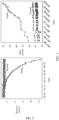
- FIG. 2 shows change trends of the receive power and the bias current when an optical module that is originally normal gradually becomes faulty.
- this application provides a method for predicting a fault of an optical module.
- a classification threshold of an operating parameter is determined based on a classification sample set corresponding to the operating parameter of optical modules; and whether a fault occurs in the future on an optical module corresponding to a sequence to be detected is predicted based on comparison results between the classification threshold and a plurality of measured values in the sequence to be detected, to help a maintenance engineer focus on an optical module on which a fault may occur, and reduce impact caused by the fault of the optical module on a service.
- the operating parameter may be a bias current of an optical module or a receive power of the optical module
- the classification threshold may be a bias current classification threshold or a receive power classification threshold.
- whether a fault occurs on an optical module in the future may be predicted based on comparison results between the bias current classification threshold and a plurality of measured values of the bias current, and/or whether a fault occurs on the optical module in the future may be predicted based on comparison results between the receive power classification threshold and a plurality of measured values of the receive power.
- the analyzer obtains the measured values of the operating parameter of the optical module by using the collector (for example, the analyzer obtains the measured values of the bias current of the optical module or the measured values of the receive power of the optical module by using the collector), and stores the obtained measured values of the operating parameter for subsequent processing.
- the analyzer obtains the classification sample set corresponding to the operating parameter, where the classification sample set includes the plurality of classification samples, and each classification sample includes one measured value of the operating parameter and one first classification identifier.
- the classification sample set is used to determine a classification threshold corresponding to the operating parameter.
- the analyzer obtains a classification sample set of the receive power
- the classification sample set of the receive power includes a plurality of classification samples of the receive power
- each classification sample of the receive power includes one measured value of the receive power and one first classification identifier corresponding to the measured value.
- the first classification identifier may be used to indicate that a classification sample is a positive sample or a negative sample.
- the first classification identifier may be indicated by using a number of bits (bit). For example, the first classification sample is indicated by using one bit. When a value of the first classification identifier is 0, it indicates that the classification sample is a positive sample; or when a value of the first classification identifier is 1, it indicates that the classification sample is a negative sample.
- the first classification identifier indicates that the classification sample is a positive sample, it indicates that the measured value in the classification sample comes from a normal optical module; and when the first classification identifier indicates that the classification sample is a negative sample, it indicates that the measured value in the classification sample comes from a faulty optical module.
- the analyzer determines a plurality of loss values based on the classification sample set and a plurality of reference classification thresholds, where each loss value corresponds to one reference classification threshold, and the analyzer determines a reference classification threshold corresponding to a smallest loss value in the plurality of loss values as the classification threshold.
- the plurality of reference classification thresholds are preset, or the plurality of reference classification thresholds are determined based on the measured value of each classification sample in the classification sample set.
- the analyzer reclassifies the samples in the classification sample set based on each of the plurality of reference classification thresholds, and determines a second classification identifier of each sample in the classification sample set based on a classification result obtained through the reclassification.
- the formula (1) is a loss function
- loss represents a mean square error of all the first classification identifiers in the classification sample set and the corresponding second classification identifiers
- N is a quantity of classification samples in the classification sample set
- N is greater than or equal to 2
- O q is a first classification identifier of a classification sample whose index value is q in the N classification samples
- P q is a second classification identifier of the classification sample whose index value is q.
- the following uses an example in which the analyzer uses the classification sample set of the receive power of an optical module, to describe the method for determining a classification threshold.
- the classification sample set of the receive power includes a plurality of classification samples of the receive power. Assuming that first classification identifiers in the plurality of classification samples of the receive power indicate that the plurality of classification samples of the receive power are all positive samples, the analyzer reclassifies the plurality of classification samples of the receive power by using the plurality of reference classification thresholds when determining the plurality of loss values. In a classification, the analyzer reclassifies the plurality of classification samples of the receive power by using one reference classification threshold, to obtain a second classification identifier of each classification sample of the receive power, and obtains a loss value based on the second classification identifier and the first classification identifier of each classification sample of the receive power.
- the analyzer reclassifies the plurality of samples of the receive power by using one reference classification threshold. For example, the analyzer compares a measured value in each classification sample of the receive power with the reference classification threshold. If a measured value in a classification sample of the receive power is less than or equal to the reference classification threshold, because the receive power presents a descending trend when the optical module becomes gradually faulty, the analyzer determines a second classification identifier of the classification sample of the receive power based on this comparison result.
- the analyzer may identify the classification sample of the receive power as a negative sample by using the second classification identifier.
- the second classification identifier may also be indicated by using a number of bits.
- the second classification identifier may be indicated by using one bit. When a value of the second classification identifier is 0, it indicates that the classification sample is a positive sample; or when a value of the second classification identifier is 1, it indicates that the classification sample is a negative sample.
- each classification sample of the receive power corresponds to one first classification identifier and one second classification identifier, and the analyzer may determine, based on the first classification identifier, the second classification identifier, and the loss function in the formula (1), the loss value corresponding to the reference classification threshold.
- a loss value may be obtained based on the loss function in the formula (1) for each reference classification threshold.
- the plurality of loss values may be obtained based on the loss function in the formula (1) for the plurality of reference classification thresholds.
- the plurality of reference classification thresholds may be preset, or the plurality of reference classification thresholds may be determined based on the measured value of each classification sample of the receive power in the classification sample set of the receive power.
- the interval is traversed by a step, a traversed value is used as a reference classification threshold, and the reference classification threshold is used to reclassify the classification samples of the receive power in the classification sample set of the receive power.
- the plurality of reference classification thresholds may be: 1.2, 1.5, 1.8, 2.1, 2.4, 2.7, and 3.
- the analyzer obtains X measured values from the X classification samples of the receive power, and sorts the X measured values (in ascending order or descending order) to obtain a sequence; and the analyzer samples the sequence by a step Y, to obtain a plurality of measured values, uses the plurality of measured values as reference classification thresholds, and reclassifies the classification samples of the receive power in the classification sample set of the receive power by using the reference classification thresholds. For example, when X is equal to 30 and Y is equal to 10, the analyzer obtains the 10 th , the 20 th , and the 30 th measured values in the 30 measured values, to obtain three reference classification thresholds.
- the analyzer can obtain the plurality of loss values based on the plurality of reference classification thresholds and by using the foregoing method for determining the loss value, and each loss value corresponds to one reference classification threshold.
- the analyzer determines the reference classification threshold corresponding to the smallest loss value in the plurality of loss values as a receive power classification threshold.
- the foregoing only uses an example in which the classification samples in the classification sample set corresponding to the receive power are positive samples for description, but is not intended to limit this application.
- the foregoing method for determining a classification threshold is also applicable to a scenario in which the classification samples in the classification sample set only include positive samples, or only include negative samples, or include both positive samples and negative samples. This is not limited in this embodiment of this application.
- obtained measured values in the negative samples of the receive power may include a measured value that is of the receive power and that is generated when the optical module is in a normal state, causing impurity of the negative samples of the receive power.
- the classification threshold may be determined mainly based on the positive samples and by using the negative samples as an important supplement, that is, accuracy of the classification threshold may be improved by intensifying the positive samples. The following describes the method.
- the classification sample set includes R positive samples and S negative samples
- the analyzer may determine the plurality of loss values based on the classification sample set and the plurality of reference classification thresholds.
- the loss values are calculated separately based on the positive samples of the receive power and the negative samples of the receive power.
- loss values corresponding to the positive samples of the receive power are calculated based on the formula (3), and loss values corresponding to the negative samples of the receive power are calculated based on the formula (4).
- a sum of the loss values corresponding to the positive samples of the receive power and the loss values corresponding to the negative samples of the receive power may be calculated based on the formula (2).
- the analyzer can obtain the plurality of loss values based on the plurality of reference classification thresholds and by using the foregoing method for determining the loss value, and each loss value corresponds to one reference classification threshold.
- the analyzer determines the reference classification threshold corresponding to the smallest loss value in the plurality of loss values as the classification threshold. If the plurality of loss values are determined based on the classification sample set corresponding to the receive power, the classification threshold corresponds to the receive power; or if the plurality of loss values are determined based on the classification sample set corresponding to a bias current, the classification threshold corresponds to the bias current.
- a relatively low fault rate of the optical module causes a small quantity of negative samples, and further causes an imbalance between the positive and negative samples.
- M groups of positive samples may be obtained through a plurality of consecutive random samplings, and one classification threshold is determined based on each group of positive samples and the same group of negative samples, that is, each group of positive samples and the group of negative samples may be used as a classification sample set, and a classification threshold corresponding to the classification sample set is obtained. Therefore, M classification sample sets are obtained based on the M groups of positive samples and the groups of negative samples. Correspondingly, the analyzer may obtain M classification thresholds corresponding to the M classification sample sets.
- the operating parameter is the receive power to describe the method for determining a classification threshold
- the method is also applicable to determine the bias current classification threshold when the operating parameter is the bias current. Therefore, for a method for determining the bias current classification threshold, refer to the foregoing related descriptions.
- the method for generating the classification threshold corresponding to the operating parameter is performed by the analyzer.
- the method for generating the classification threshold corresponding to the operating parameter in this application may alternatively be performed by a controller.
- the controller may actively send, or may send in response to a request from the analyzer, the determined classification threshold to the analyzer.
- the controller may be configured to manage a plurality of analyzers.
- the controller may also communicate with one or more collectors, and obtain measured values of the operating parameter that are collected by the one or more collectors, so as to generate a fault prediction model or the classification threshold corresponding to the operating parameter.
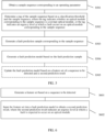
- the following describes, with reference to FIG. 4 , a method for predicting whether an optical module enters a faulty mode that is provided in this application.
- the method is performed by the analyzer, and includes S401 to S403.
- the analyzer obtains the sequence to be detected of the optical module in the preset time period, where the sequence to be detected includes the plurality of measured values corresponding to the operating parameter of the optical module that are generated in the preset time period.
- the optical module is an optical module to be detected, the plurality of measured values may be collected by the collector by monitoring the optical module to be detected and sent to the analyzer.
- the collector may send the collected measured values of the operating parameter to the analyzer in real time, or may send the collected measured values of the operating parameter to the analyzer according to an instruction or based on a specified period.
- the analyzer obtains a plurality of measured values of an operating parameter of an optical module in a preset time period (for example, 30 days), and the plurality of measured values of the operating parameter that are obtained in the time period may be referred to as the sequence to be detected.
- the analyzer stores 30 measured values of the receive power after 30 days.
- the operating parameter is a bias current
- one measured value of the bias current of the optical module is obtained every day. Therefore, the analyzer stores 30 measured values of the bias current after 30 days.
- the analyzer obtains the classification threshold corresponding to the operating parameter, where the classification threshold is determined based on the classification sample set corresponding to the operating parameter.
- the analyzer obtains a receive power classification threshold, and the receive power classification thresholdis determined based on a classification sample set of the receive power; or when the operating parameter is the bias current, the analyzer obtains a bias current classification threshold, and the bias current classification threshold is determined based on a classification sample set of the bias current.
- the analyzer may obtain the classification threshold corresponding to the operating parameter.
- the classification threshold corresponding to the operating parameter may be generated by the analyzer, or may be obtained by the analyzer from a controller.
- a specific obtaining manner is not limited in this application.
- S403. Determine a first prediction result of the optical module based on comparison results between the classification threshold corresponding to the operating parameter and the plurality of measured values in the sequence to be detected, where the first prediction result indicates whether the optical module enters a faulty mode.
- the analyzer may compare the classification threshold with the plurality of measured values in the sequence to be detected, and determine the first prediction result of the optical module based on the comparison results between the classification threshold and the plurality of measured values in the sequence to be detected, where the first prediction result indicates whether the optical module enters the faulty mode.
- the analyzer compares the 30 measured values of the receive power with the receive power classification threshold. If at least one of the 30 measured values of the receive power is less than or equal to the receive power classification threshold, the first prediction result determined by the analyzer indicates that the optical module enters the faulty mode; or if all the 30 measured values of the receive power are greater than the receive power classification threshold, the first prediction result determined by the analyzer indicates that the optical module does not enter the faulty mode.
- the analyzer compares the 30 measured values of the bias current with the bias current classification threshold. If at least one of the 30 measured values of the bias current is greater than or equal to the bias current classification threshold, the first prediction result determined by the analyzer indicates that the optical module enters the faulty mode; or if all the 30 measured values of the bias current are less than the bias current classification threshold, the first prediction result determined by the analyzer indicates that the optical module does not enter the faulty mode It can be seen that when the classification threshold corresponding to the operating parameter is used to predict whether the optical module enters the faulty mode, only whether the optical module enters the faulty mode can be determined.
- an urgency level at which a fault occurs after the optical module enters the faulty mode cannot be determined.
- a feature set generated based on the sequence to be detected may further be input into a fault prediction model, and the urgency level at which a fault occurs after the optical module enters the faulty mode is further determined by using the fault prediction model.
- the fault prediction model used in this application may be generated by the analyzer or the controller.
- the following describes, with reference to FIG. 5 , a method for generating a fault prediction model that is provided in this application, and the method includes S501 to S504.
- a sequence to be detected and the sample sequence both include measured values corresponding to the operating parameter, but are used in different scenarios:
- the sequence to be detected corresponds to an optical module to be detected, and has real-time quality. For example, as long as the collector collects a sequence to be detected of an optical module, the collector sends the sequence to be detected to the analyzer, to ensure timeliness and accuracy of a prediction result of predicting whether a fault occurs on the optical module in the future.
- the sample sequence corresponding to the operating parameter is used to generate a fault prediction model.
- the collector may first collect a large quantity of sample sequences and then send all the sample sequences to the analyzer, or may separately send each sample sequence to the analyzer after collecting the sample sequence.
- Each sample sequence includes a measured value corresponding to a same optical module, but different sample sequences may correspond to different optical modules.
- the collector does not distinguish sample sequences, but sends, to the analyzer, all collected measured values corresponding to an operating parameter of each optical module, and the analyzer determines, based on all the received measured values, a sample sequence corresponding to the operating parameter.
- the analyzer When the operating parameter is a receive power, the analyzer obtains a sample sequence of the receive power of the optical module, and when the operating parameter is a bias current, the analyzer obtains a sample sequence of the bias current of the optical module.
- a time length from a current moment to the collection start moment is greater than or equal to 60 days.
- S502. Determine a tag of the sample sequence based on a classification threshold and the sample sequence, where the tag indicates whether the optical module corresponding to the sample sequence is a normal optical module, or the tag indicates an urgency level at which a fault occurs on the optical module corresponding to the sample sequence.
- the analyzer may determine the tag of the sample sequence based on the classification threshold and the sample sequence that correspond to the operating parameter, where the tag may indicate whether the optical module corresponding to the sample sequence is a normal optical module, or the tag may indicate the urgency level at which a fault occurs on the optical module corresponding to the sample sequence.
- the analyzer may compare measured values in the sample sequence of the receive power with a receive power classification threshold, and determine, if at least one measured value of the receive power is less than or equal to the receive power classification threshold, that the optical module corresponding to the sample sequence enters a faulty mode.
- the analyzer may determine the tag of the sample sequence based on a time interval between a collection end moment of the sample sequence and a moment at which a fault occurs on the optical module corresponding to the sample sequence, where the tag indicates an urgency level at which a fault occurs on the optical module corresponding to the sample sequence.
- a current moment is the 120 th day from a collection start moment.
- a time interval between the collection end moment of the sample sequence and a moment at which a fault occurs on the optical module corresponding to the sample sequence is 20.
- the analyzer may determine, based on the time interval, that a fault occurs on the optical module corresponding to the sample sequence after 20 days starting from the 60 th day.
- the analyzer may further compare the value 20 with a preset time interval threshold, where for example, the time interval threshold is 30; and determine, based on a comparison result between the time interval and the time interval threshold, an urgency level at which a fault occurs on the optical module corresponding to the sample sequence.
- the analyzer determines that the time interval 20 is less than the time interval threshold 30, and may determine that, the tag of the sample sequence indicates that the urgency level at which a fault occurs on the optical module from the collection end moment (the 60 th day) of the sample sequence is urgent.
- the tag of the sample sequence indicates that the optical module corresponding to the sample sequence is a normal optical module.
- the analyzer may compare measured values in the sample sequence of the bias current with a bias current classification threshold, and may determine, if at least one measured value of the bias current is greater than or equal to the bias current classification threshold, that the optical module corresponding to the sample sequence enters a faulty mode.
- the analyzer may determine the tag of the sample sequence based on a time interval between a collection end moment of the sample sequence and a moment at which a fault occurs on the optical module corresponding to the sample sequence, where the tag indicates an urgency level at which a fault occurs on the optical module corresponding to the sample sequence.
- a current moment is the 180 th day from a collection start moment.
- the analyzer already knows that a fault occurs on the optical module corresponding to the sample sequence on the 150 th day
- the time interval between the collection end moment of the sample sequence and the moment at which a fault occurs on the optical module corresponding to the sample sequence is 60.
- the analyzer may determine, based on the time interval, that a fault occurs on the optical module corresponding to the sample sequence after 60 days starting from the 90 th day.
- the analyzer may further compare the value 60 with a preset time interval threshold, where for example, the time interval threshold is 30; and determine, based on a comparison result between the time interval and the time interval threshold, the urgency level at which a fault occurs on the optical module corresponding to the sample sequence.
- the analyzer determines that the time interval 60 is greater than the time interval threshold 30, and may determine that, the tag of the sample sequence indicates that the urgency level at which a fault occurs on the optical module from the collection end moment (the 90 th day) of the sample sequence is less urgent.
- the tag of the sample sequence indicates that the optical module corresponding to the sample sequence is a normal optical module.
- a value of the tag may be 0, 1, or 2, where 0 indicates that the optical module is a normal optical module, 1 indicates that the time interval of the optical module from the collection end moment to the moment at which a fault occurs is less than or equal to the preset time interval threshold (that is, the urgency level at which a fault occurs is urgent), and 2 indicates that the time interval of the optical module from the collection end moment to the moment at which a fault occurs is greater than the preset time interval threshold (that is, the urgency level at which a fault occurs is less urgent).
- the analyzer determines the tag of the sample sequence corresponding to the operating parameter, and may generate, based on the sample sequence and the determined tag, the fault prediction sample corresponding to the sample sequence, where the fault prediction sample includes the feature set of the sample sequence and the tag of the sample sequence.
- the feature set of the sample sequence and the tag of the sample sequence may be separately used as an output and an input, so that the fault prediction model learns the input and the output, to train the fault prediction model.
- time interval threshold and the value of the tag that are listed above are both used as examples, and do not constitute a limitation on this application.
- a form and the value of the tag may be set.
- one sample sequence comes from a same optical module.
- an example in which a feature set determined based on one sample sequence is input into the fault prediction model is used to describe a method for training the fault prediction model.
- feature sets determined based on a large quantity of sample sequences are input into the fault prediction model, to train the fault prediction model.
- the analyzer is used as an example to describe a process of generating the fault prediction model.
- a controller may alternatively generate the fault prediction model based on the method shown in FIG. 5 .
- the analyzer may perform one or more steps in steps S501 to S503, and the controller performs a step in FIG. 5 other than the step performed by the analyzer. If step S504 is performed by the controller, the controller needs to actively send, or send in response to a request from the analyzer, the generated fault prediction model to the analyzer.
- a method for determining an urgency level at which a fault might occurs on an optical module that is provided in this application is described below with reference to FIG. 6 , and the method includes S601 to S602.
- S602. Input the feature set into a fault prediction model to obtain a second prediction result, where the second prediction result indicates an urgency level at which a fault is expected to occur on the optical module.
- the analyzer generates the feature set of the sequence to be detected, and in S602, the analyzer inputs the feature set into the fault prediction model to obtain the second prediction result, where the second prediction result indicates the urgency level at which a fault is expected to occur on the optical module.
- the analyzer inputs the feature set of the sequence to be detected into the fault prediction model, the fault prediction model outputs the second prediction result, and the second prediction result indicates the urgency level at which a fault is expected to occur on the optical module.
- the urgency level at which a fault is expected to occur on the optical module may be indicated by using a value relationship between a preset time interval threshold and a time interval from a current moment to a moment at which a fault occurs.
- a value of the second prediction result when a value of the second prediction result is 1, it indicates that the time interval of the optical module from the current moment to the moment at which a fault occurs is less than or equal to the preset time interval threshold; and when the value of the second prediction result is 2, it indicates that the time interval of the optical module from the current moment to the moment at which a fault occurs is greater than the preset time interval threshold.
- the feature set of the sequence to be detected is generated, and the feature set is input into the fault prediction model, so that the fault prediction model can predict the urgency level at which a fault occurs on the optical module from a current moment, to help a maintenance engineer process, based on the urgency level at which a fault occurs on the optical module, the optical module as soon as possible in a relatively short time, and reduce impact caused by the fault of the optical module on a service.
- an obtained second prediction result is determined based on the feature set corresponding to the bias current; and when a feature set corresponding to a receive power is input to the fault prediction model, an obtained second prediction result is determined based on the feature set corresponding to the receive power.
- the fault prediction model obtains a prediction result corresponding to the bias current (for example, a third prediction result) and a prediction result corresponding to the receive power (for example, a fourth prediction result).
- the fault prediction model may determine the second prediction result with reference to both the third prediction result and the fourth prediction result.
- a value of the third prediction result that is obtained after the fault prediction model processes the feature set corresponding to the receive power is 1, and a value of the fourth prediction result that is obtained after the fault prediction model processes the feature set corresponding to the bias current is 2.
- the third prediction result whose value is 1 indicates that the time interval of the optical module from the current moment to the moment at which a fault occurs is less than or equal to the preset time interval threshold
- the fourth prediction result whose value is 2 indicates that the time interval of the optical module from the current moment to the moment at which a fault occurs is greater than the preset time interval threshold.
- the third prediction result whose value is 1 corresponds to a higher urgency level. Therefore, the fault prediction model may determine the third prediction result whose value is 1 as the second prediction result of the optical module, and finally output the second prediction result.
- the second prediction result may be determined based on Table 1 (using an example in which values of the prediction result include 0, 1, and 2 for description):
- the fault prediction model obtains two prediction results.
- the fault prediction model uses a prediction result having a higher urgency level in the two prediction results as the prediction result for the optical module, so that the maintenance engineer can process, as soon as possible, the optical module on which a fault may occur, and the impact caused by the fault of the optical module on the service can be reduced.
- the fault prediction model may further be updated based on the feature set of the sequence to be detected and the second prediction result.
- the method for generating a fault prediction model may further include S505: S505. Update the fault prediction model based on the feature set of the sequence to be detected and the second prediction result.
- the analyzer may use the second prediction result and the feature set corresponding to the sequence to be detected as an input of the fault prediction model, so that the fault prediction model learns the input and an output, to complete update of the fault prediction model, and a prediction result of the fault prediction model is more accurate.
- Sequence numbers in the foregoing methods in FIG. 3 to FIG. 6 do not mean execution sequences.
- the execution sequences of the processes should be determined based on functions and internal logic of the processes, and should not be construed as any limitation on the implementation processes of the embodiments of this application.
- the foregoing methods may further be combined to provide more implementations. Other implementations obtained by any combination of the foregoing methods should all be considered as falling within the protection scope of this application.
- the method for predicting a fault of an optical module that is provided in the embodiments of this application is described in detail above with reference to FIG. 1 and FIG. 6 .
- An apparatus for predicting a fault of an optical module that is provided in the embodiments of this application is described in detail below with reference to FIG. 7 and FIG. 8 .
- FIG. 7 is a schematic block diagram of an apparatus 700 for predicting a fault of an optical module according to this application.
- the apparatus 700 includes:
- the apparatus further includes a preprocessing module 704 and a fault prediction model 705.
- the preprocessing module 704 is configured to: generate a feature set based on the sequence to be detected when the first prediction result indicates that the optical module enters the faulty mode; and input the feature set into the fault prediction model.
- the fault prediction model 705 is configured to obtain a second prediction result based on the feature set, where the second prediction result indicates an urgency level at which a fault is expected to occur on the optical module.
- the apparatus further includes:
- the training module 707 is further configured to update the fault prediction model based on the feature set of the sequence to be detected and the second prediction result.
- the apparatus further includes a fourth obtaining module 708 and a calculation module 709.
- the fourth obtaining module 708 is configured to obtain the classification sample set corresponding to the operating parameter, where the classification sample set includes a plurality of classification samples, and each classification sample includes one measured value of the operating parameter and one first classification identifier.
- the calculation module 709 is configured to determine, based on the classification sample set, the classification threshold corresponding to the operating parameter.
- calculation module 709 is further configured to:
- calculation module 709 is further configured to:
- the classification sample set includes R positive samples and S negative samples
- the calculation module 709 is further configured to:
- the operating parameter corresponds to M classification sample sets
- the calculation module 709 is further configured to:
- the operating parameter is a bias current
- the classification threshold is a bias current classification threshold
- the sample sequence is a sample sequence of the bias current
- the training module 707 is further configured to:
- the operating parameter is a receive power
- the classification threshold is a receive power classification threshold
- the sample sequence is a sample sequence of the receive power
- the training module 707 is further configured to:
- the feature set includes a feature set corresponding to a bias current and a feature set corresponding to a receive power.
- the preprocessing module 704 is further configured to input the feature set corresponding to the bias current and the feature set corresponding to the receive power into the fault prediction model.
- the fault prediction model 705 is further configured to: obtain a third prediction result corresponding to the bias current and a fourth prediction result corresponding to the receive power; and obtain the second prediction result based on the third prediction result and the fourth prediction result.
- the first obtaining module 701 obtains the sequence to be detected by using a collector
- the second obtaining module 702 obtains, from the calculation module 709, the classification threshold that corresponds to the operating parameter and that is determined by the calculation module 709
- the third obtaining module 706 obtains the sample sequence corresponding to the operating parameter by using the collector
- the fourth obtaining module 708 obtains the classification sample set corresponding to the operating parameter by using the collector.
- the first obtaining module 701, the third obtaining module 706, and the fourth obtaining module 708 may be a same obtaining module, or the first obtaining module 701, the second obtaining module 702, the third obtaining module 706, and the fourth obtaining module 708 may be a same obtaining module. This is not limited in this embodiment of this application.
- the apparatus 700 in this application may be implemented by using an application-specific integrated circuit (application-specific integrated circuit, ASIC), or a programmable logic device (programmable logic device, PLD).
- the PLD may be a complex programmable logic device (complex programmable logic device, CPLD), a field-programmable gate array (field-programmable gate array, FPGA), generic array logic (generic array logic, GAL), or any combination thereof.
- the method for predicting a fault of an optical module that is shown in FIG. 3 to FIG. 6 may alternatively be implemented by using software.
- the apparatus 700 and the modules of the apparatus 700 may be software modules when the method for predicting a fault of an optical module that is shown in FIG. 3 to FIG. 6 is implemented by using software.
- the apparatus 700 may correspondingly perform the method described in this application, and the foregoing and other operations and/or functions of all the units in the apparatus 700 are used to implement corresponding procedures that are performed by the analyzer or the controller in the method for predicting a fault of an optical module that is shown in FIG. 3 to FIG. 6 .
- the analyzer or the controller may be used to implement corresponding procedures that are performed by the analyzer or the controller in the method for predicting a fault of an optical module that is shown in FIG. 3 to FIG. 6 .
- details are not described herein again.
- the collector in FIG. 7 is independent of the apparatus 700, located outside the apparatus 700, and connected to the apparatus 700.
- the collector may be located inside the apparatus 700, that is, the collector may alternatively be a part of the apparatus 700. This is not limited in this embodiment of this application.
- FIG. 8 is a schematic structural diagram of hardware of an apparatus 800 for predicting a fault of an optical module according to an embodiment of this application.
- the apparatus 800 (the apparatus 800 may be specifically a computing device) for predicting a fault of an optical module that is shown in FIG. 8 includes a memory 801, a processor 802, a communications interface 803, and a bus 804.
- the memory 801, the processor 802, and the communications interface 803 implement communication connection between each other through the bus 804.
- the memory 801 may be a read-only memory (read-only memory, ROM), a static storage device, a dynamic storage device, or a random access memory (random access memory, RAM).
- the memory 801 may store a program, and when the program stored in the memory 801 is executed by the processor 802, the processor 802 and the communications interface 803 are configured to perform the steps in the method for predicting a fault of an optical module in the embodiments of this application.
- the processor 802 may be a general purpose central processing unit (central processing unit, CPU), a microprocessor, an ASIC, a graphics processing unit (graphics processing unit, GPU), or one or more integrated circuits, and is configured to execute a related program, so as to implement functions that the units in the apparatus for predicting a fault of an optical module need to perform in the embodiments of this application; or is configured to perform the method for predicting a fault of an optical module in the embodiments of this application.
- CPU central processing unit
- ASIC application-specific integrated circuits
- GPU graphics processing unit
- the processor 802 may alternatively be an integrated circuit chip and has a signal processing capability. In an implementation process, the steps in the method for predicting a fault of an optical module in this application may be implemented by using an integrated logic circuit in hardware form or an instruction in a software form in the processor 802.
- the processor 802 may alternatively be a general purpose processor, a digital signal processor (digital signal processor, DSP), an ASIC, a field-programmable gate array (field-programmable gate array, FPGA) or another programmable logical device, a discrete gate or transistor logic device, or a discrete hardware component, and may implement or perform the methods, the steps, and logical block diagrams that are disclosed in the embodiments of this application.
- the general purpose processor may be a microprocessor or any conventional processor.
- the steps in the method disclosed in the embodiments of this application may be implemented by a hardware decoding processor, or by a combination of hardware and a software module in the decoding processor.
- the software module may be located in a mature storage medium in the art, such as a random access memory, a flash memory, a read-only memory, a programmable read-only memory, an electrically erasable programmable memory, or a register.
- the storage medium is located in the memory 801, the processor 802 reads information in the memory 801, and may complete, in combination with hardware in the processor 802, functions that the units included in the apparatus for predicting a fault of an optical module in the embodiments of this application need to perform, or perform the method for predicting a fault of an optical module in the embodiments of this application.
- the communications interface 803 uses, for example but not limited to, a transceiver apparatus of a transceiver type, to implement communication between the apparatus 800 and another device or a communications network. For example, a sample sequence corresponding to an operating parameter and a classification sample set corresponding to the operating parameter may be obtained through the communications interface 803.
- the bus 804 may include a channel on which information is transmitted between the components (for example, the memory 801, the processor 802, and the communications interface 803) of the apparatus 800.
- the apparatus 800 shown in FIG. 8 only shows the memory, the processor, and the communications interface, in a specific implementation process, a person skilled in the art should understand that the apparatus 800 further includes other components that are necessary to implement normal running. In addition, based on a specific requirement, a person skilled in the art should understand that the apparatus 800 may further include hardware components for implementing other additional functions. In addition, a person skilled in the art should understand that the apparatus 800 may only include components that are necessary to implement the embodiments of this application, but does not need to include all the components shown in FIG. 8 .
- apparatus 800 is equivalent to the analyzer in the embodiments of this application.
- a person of ordinary skill in the art may be aware that, in combination with the examples described in the embodiments disclosed in this specification, units and algorithm steps may be implemented by electronic hardware or a combination of computer software and electronic hardware. Whether the functions are performed by hardware or software depends on particular applications and design constraints of the technical solutions. A person skilled in the art may use different methods to implement the described functions for each particular application, but it should not be considered that the implementation goes beyond the scope of this application.
- An embodiment of this application further provides a computer-readable storage medium, the computer-readable storage medium includes a computer program, and when the computer program is run on a computer, the computer is enabled to perform the method provided in the foregoing method embodiments.
- An embodiment of this application further provides a computer program product that includes an instruction, and when the computer program product is run on a computer, the computer is enabled to perform the method provided in the foregoing method embodiments.
- An embodiment of this application further provides a system.
- the system includes a collector, an apparatus for predicting a fault of an optical module, and an optical module.
- the collector is configured to collect measured values of an operating parameter related to the optical module, and sends the collected measured values to the apparatus for predicting a fault of an optical module.
- the measured values of the operating parameter related to the optical module may include a sequence to be detected of the optical module in a preset time period, a sample sequence corresponding to the operating parameter, and the like.
- the apparatus for predicting a fault of an optical module is configured to receive the measured values of the operating parameter related to the optical module that are sent by the collector, and perform the method in any one of FIG. 3 to FIG. 6 based on the measured values.
- the apparatus for predicting a fault of an optical module may be the analyzer shown in FIG. 1 , the apparatus 700 shown in FIG. 7 , or the apparatus 800 shown in FIG. 8 .
- the system includes one optical module.
- the system may include a plurality of optical modules, and the collector needs to collect measured values of an operating parameter related to each optical module.
- the disclosed system, apparatus, and method may be implemented in other manners.
- the described apparatus embodiment is merely an example.
- the unit division is merely logical function division and may be other division in an actual implementation.
- a plurality of units or components may be combined or integrated into another system, or some features may be ignored or not performed.
- the displayed or discussed mutual couplings or direct couplings or communication connections may be implemented by using some interfaces.
- the indirect couplings or communication connections between the apparatuses or units may be implemented in electronic, mechanical, or other forms.
- the units described as separate parts may or may not be physically separate, and parts displayed as units may or may not be physical units, may be located in one position, or may be distributed on a plurality of network units. Some or all of the units may be selected based on actual requirements to achieve the objectives of the solutions of the embodiments.
Landscapes
- Engineering & Computer Science (AREA)
- Physics & Mathematics (AREA)
- Signal Processing (AREA)
- Computer Networks & Wireless Communication (AREA)
- Electromagnetism (AREA)
- Artificial Intelligence (AREA)
- Evolutionary Computation (AREA)
- Data Mining & Analysis (AREA)
- Computer Vision & Pattern Recognition (AREA)
- Theoretical Computer Science (AREA)
- Evolutionary Biology (AREA)
- General Engineering & Computer Science (AREA)
- General Physics & Mathematics (AREA)
- Bioinformatics & Cheminformatics (AREA)
- Life Sciences & Earth Sciences (AREA)
- Bioinformatics & Computational Biology (AREA)
- Databases & Information Systems (AREA)
- Medical Informatics (AREA)
- Software Systems (AREA)
- Probability & Statistics with Applications (AREA)
- Optical Communication System (AREA)
Claims (14)
- Verfahren zum Vorhersagen eines Fehlers eines optischen Moduls, umfassend:Erlangen (S401) einer zu detektierenden Sequenz des optischen Moduls in einem voreingestellten Zeitraum, wobei die zu detektierende Sequenz eine Vielzahl gemessener Werte eines Betriebsparameters des optischen Moduls umfasst;Erlangen (S402) eines Klassifizierungsschwellenwerts, der dem Betriebsparameter entspricht;Bestimmen (S403) eines ersten Vorhersageergebnisses des optischen Moduls basierend auf Vergleichsergebnissen zwischen dem Klassifizierungsschwellenwert, der dem Betriebsparameter entspricht, und der Vielzahl gemessener Werte in der zu detektierenden Sequenz, wobei das erste Vorhersageergebnis angibt, ob das optische Modul in einen fehlerhaften Modus eintritt; undErlangen (S602) eines zweiten Vorhersageergebnisses, wenn das erste Vorhersageergebnis angibt, dass das optische Modul in den fehlerhaften Modus eintritt, wobei das zweite Vorhersageergebnis ein Dringlichkeitsniveau angibt, auf dem erwartet wird, dass ein Fehler an dem optischen Modul auftritt;dadurch gekennzeichnet, dass das Erlangen des zweiten Vorhersageergebnisses Folgendes umfasst:Erzeugen (S601) eines Merkmalssatzes basierend auf der zu detektierenden Sequenz; undEingeben (S602) des Merkmalssatzes in ein Fehlervorhersagemodell, um das zweite Vorhersageergebnis zu erlangen.
- Verfahren nach Anspruch 1, wobei das Verfahren ferner Folgendes umfasst:Erlangen (S501) einer Probensequenz, die dem Betriebsparameter entspricht;Bestimmen (S502) einer Markierung der Probensequenz basierend auf dem Klassifizierungsschwellenwert und der Probensequenz, wobei die Markierung angibt, ob ein optisches Modul, das der Probensequenz entspricht, ein normales optisches Modul ist, oder die Markierung ein Dringlichkeitsniveau angibt, auf dem ein Fehler an dem optischen Modul auftritt, das der Probensequenz entspricht;Erzeugen (S503) einer Fehlervorhersageprobe, die der Probensequenz entspricht, wobei die Fehlervorhersageprobe einen Merkmalssatz der Probensequenz und die Markierung der Probensequenz umfasst; undErzeugen (S504) des Fehlervorhersagemodells basierend auf der Fehlervorhersageprobe.
- Verfahren nach Anspruch 2, wobei das Verfahren ferner Folgendes umfasst:
Aktualisieren des Fehlervorhersagemodells basierend auf dem Merkmalssatz der zu detektierenden Sequenz und dem zweiten Vorhersageergebnis. - Verfahren nach einem der Ansprüche 1 bis 3, wobei das Verfahren vor dem Erlangen eines Klassifizierungsschwellenwerts, der dem Betriebsparameter entspricht, ferner Folgendes umfasst:Erlangen (S301) des Klassifizierungsprobensatzes, der dem Betriebsparameter entspricht, wobei der Klassifizierungsprobensatz eine Vielzahl von Klassifizierungsproben umfasst und jede Klassifizierungsprobe einen gemessenen Wert des Betriebsparameters und eine erste Klassifizierungskennung umfasst; undBestimmen (S302), basierend auf dem Klassifizierungsprobensatz, des Klassifizierungsschwellenwerts, der dem Betriebsparameter entspricht.
- Verfahren nach Anspruch 4, wobei das Bestimmen, basierend auf dem Klassifizierungsprobensatz, des Klassifizierungsschwellenwerts, der dem Betriebsparameter entspricht, Folgendes umfasst:Bestimmen einer Vielzahl von Verlustwerten basierend auf dem Klassifizierungsprobensatz und einer Vielzahl von Referenzklassifizierungsschwellenwerten, wobei jeder Verlustwert einem Referenzklassifizierungsschwellenwert entspricht und die Vielzahl von Referenzklassifizierungsschwellenwerten voreingestellt ist oder die Vielzahl von Referenzklassifizierungsschwellenwerten basierend auf dem gemessenen Wert jeder Klassifizierungsprobe in dem Klassifizierungsprobensatz bestimmt wird;Bestimmen eines Referenzklassifizierungsschwellenwerts, der einem kleinsten Verlustwert in der Vielzahl von Verlustwerten entspricht, als einen Klassifizierungsschwellenwert, der dem Klassifizierungsprobensatz entspricht; undBestimmen, basierend auf dem Klassifizierungsschwellenwert, der dem Klassifizierungsprobensatz entspricht, des Klassifizierungsschwellenwerts, der dem Betriebsparameter entspricht.
- Verfahren nach Anspruch 5, wobei das Bestimmen einer Vielzahl von Verlustwerten basierend auf dem Klassifizierungsprobensatz und einer Vielzahl von Referenzklassifizierungsschwellenwerten Folgendes umfasst:Reklassifizieren der Klassifizierungsproben in dem Klassifizierungsprobensatz basierend auf jedem der Vielzahl von Referenzklassifizierungsschwellenwerten und Bestimmen einer zweiten Klassifizierungskennung jeder Klassifizierungsprobe in dem Klassifizierungsprobensatz basierend auf einem Klassifizierungsergebnis; undBestimmen, basierend auf der folgenden Verlustfunktion und der zweiten Klassifizierungskennung und der ersten Klassifizierungskennung jeder Klassifizierungsprobe, eines Verlustwerts, der dem Referenzklassifizierungsschwellenwert entspricht:
 wobei Verlust einen mittleren quadratischen Fehler aller ersten Klassifizierungskennungen in dem Klassifizierungsprobensatz und der entsprechenden zweiten Klassifizierungskennungen darstellt, N eine Menge von Klassifizierungsproben in dem Klassifizierungsprobensatz ist, N größer oder gleich 2 ist, Oq eine erste Klassifizierungskennung einer Klassifizierungsprobe ist, deren Indexwert q in den N Klassifizierungsproben ist, und Pq eine zweite Klassifizierungskennung der Klassifizierungsprobe ist, deren Indexwert q ist.
 - Verfahren nach Anspruch 5, wobei der Klassifizierungsprobensatz R positive Proben und S negative Proben umfasst und das Bestimmen einer Vielzahl von Verlustwerten basierend auf dem Klassifizierungsprobensatz und einer Vielzahl von Referenzklassifizierungsschwellenwerten Folgendes umfasst:Reklassifizieren der Klassifizierungsproben in dem Klassifizierungsprobensatz basierend auf jedem der Vielzahl von Referenzklassifizierungsschwellenwerten und Bestimmen einer zweiten Klassifizierungskennung jeder Klassifizierungsprobe in dem Klassifizierungsprobensatz basierend auf einem Klassifizierungsergebnis; undBestimmen, basierend auf der folgenden Verlustfunktion und der zweiten Klassifizierungskennung und der ersten Klassifizierungskennung jeder Klassifizierungsprobe, eines Verlustwerts, der dem Referenzklassifizierungsschwellenwert entspricht:
 wobei Verlust einen mittleren quadratischen Fehler aller ersten Klassifizierungskennungen in dem Klassifizierungsprobensatz und der entsprechenden zweiten Klassifizierungskennungen darstellt, Verlustf einen mittleren quadratischen Fehler der ersten Klassifizierungskennungen in allen positiven Proben und entsprechenden zweiten Klassifizierungskennungen darstellt, Verlustn einen mittleren quadratischen Fehler der ersten Klassifizierungskennungen in allen negativen Proben und entsprechenden zweiten Klassifizierungskennungen darstellt, R größer oder gleich 2 ist, Oa eine erste Klassifizierungskennung einer positiven Probe ist, deren Indexwert a ist, Pa eine zweite Klassifizierungskennung der positiven Probe ist, deren Indexwert a ist, S größer oder gleich 2 ist, Ob eine erste Klassifizierungskennung einer negativen Probe ist, deren Indexwert b ist, Pb eine zweite Klassifizierungskennung der negativen Probe ist, deren Indexwert b ist, c ein Gewichtungskoeffizient ist und c größer oder gleich 1 ist.
 - Verfahren nach einem der Ansprüche 5 bis 7, wobei der Betriebsparameter M Klassifizierungsprobensätzen entspricht und das Bestimmen, basierend auf dem Klassifizierungsschwellenwert, der dem Klassifizierungsprobensatz entspricht, des Klassifizierungsschwellenwerts, der dem Betriebsparameter entspricht, Folgendes umfasst:Bestimmen von M Klassifizierungsschwellenwerten, die den M Klassifizierungsprobensätzen entsprechen; undBestimmen, basierend auf der folgenden Funktion, des Klassifizierungsschwellenwerts, der dem Betriebsparameter entspricht:
 wobei Schwellenwfinal der Klassifizierungsschwellenwert ist, der dem Betriebsparameter entspricht, Schwellenwi ein Klassifizierungsschwellenwert ist, der einem i-ten Klassifizierungsprobensatz entspricht, und M größer als 1 ist.
 - Verfahren nach Anspruch 2 oder 3, wobei der Betriebsparameter ein Ruhestrom ist, der Klassifizierungsschwellenwert ein Ruhestromklassifizierungsschwellenwert ist, die Probensequenz eine Probensequenz des Ruhestroms ist und das Bestimmen einer Markierung der Probensequenz basierend auf dem Klassifizierungsschwellenwert und der Probensequenz Folgendes umfasst:
wenn die Probensequenz mindestens einen gemessenen Wert umfasst, der größer oder gleich dem Ruhestromklassifizierungsschwellenwert ist, Bestimmen der Markierung der Probensequenz basierend auf einem Zeitintervall zwischen einem Erfassungsendzeitpunkt der Probensequenz und einem Zeitpunkt, zu dem ein Fehler an dem optischen Modul auftritt, das der Probensequenz entspricht, wobei die Markierung das Dringlichkeitsniveau angibt, auf dem ein Fehler an dem optischen Modul auftritt, das der Probensequenz entspricht; oder wenn alle gemessenen Werte in der Probensequenz kleiner als der Ruhestromklassifizierungsschwellenwert sind, Bestimmen der Markierung der Probensequenz, wobei die Markierung angibt, dass das optische Modul, das der Probensequenz entspricht, ein normales optisches Modul ist. - Verfahren nach Anspruch 2 oder 3, wobei der Betriebsparameter eine Empfangsleistung ist, der Klassifizierungsschwellenwert ein Empfangsleistungsklassifizierungsschwellenwert ist, die Probensequenz eine Probensequenz der Empfangsleistung ist und das Bestimmen einer Markierung der Probensequenz basierend auf dem Klassifizierungsschwellenwert und der Probensequenz Folgendes umfasst:wenn die Probensequenz mindestens einen gemessenen Wert umfasst, der kleiner oder gleich dem Empfangsleistungsklassifizierungsschwellenwert ist, Bestimmen der Markierung der Probensequenz basierend auf einem Zeitintervall zwischen einem Erfassungsendzeitpunkt der Probensequenz und einem Zeitpunkt, zu dem ein Fehler an dem optischen Modul auftritt, das der Probensequenz entspricht, wobei die Markierung das Dringlichkeitsniveau angibt, auf dem ein Fehler an dem optischen Modul auftritt, das der Probensequenz entspricht; oderwenn alle gemessenen Werte in der Probensequenz größer als der Empfangsleistungsklassifizierungsschwellenwert sind, Bestimmen der Markierung der Probensequenz, wobei die Markierung angibt, dass das optische Modul, das der Probensequenz entspricht, ein normales optisches Modul ist.
- Verfahren nach einem der Ansprüche 1 bis 3, wobei der Merkmalssatz einen Merkmalssatz, der einem Ruhestrom entspricht, und einen Merkmalssatz, der einer Empfangsleistung entspricht, umfasst und das Eingeben des Merkmalssatzes in ein Fehlervorhersagemodell zum Erlangen eines zweiten Vorhersageergebnisses Folgendes umfasst:Eingeben des Merkmalssatzes, der dem Ruhestrom entspricht, und des Merkmalssatzes, der der Empfangsleistung entspricht, in das Fehlervorhersagemodell, um ein drittes Vorhersageergebnis, das dem Ruhestrom entspricht, und ein viertes Vorhersageergebnis, das der Empfangsleistung entspricht, zu erlangen; undBestimmen des zweiten Vorhersageergebnisses basierend auf dem dritten Vorhersageergebnis und dem vierten Vorhersageergebnis.
- Vorrichtung (700) zum Vorhersagen eines Fehlers eines optischen Moduls, das dazu konfiguriert ist, das Verfahren nach einem der Ansprüche 1-11 umzusetzen.
- Computerprogramm, wobei, wenn das Computerprogramm auf einem Computer läuft, es dem Computer ermöglicht wird, das Verfahren nach einem der Ansprüche 1 bis 11 durchzuführen.
- System zum Vorhersagen eines Fehlers eines optischen Moduls, umfassend das optische Modul, einen Kollektor und die Vorrichtung (700) zum Vorhersagen eines Fehlers eines optischen Moduls nach Anspruch 12, wobei:
der Kollektor zu Folgendem konfiguriert ist: Erfassen einer zu detektierenden Sequenz des optischen Moduls in einem voreingestellten Zeitraum, wobei die zu detektierende Sequenz eine Vielzahl gemessener Werte eines Betriebsparameters des optischen Moduls umfasst; und Senden der zu detektierenden Sequenz an die Vorrichtung (700) zum Vorhersagen eines Fehlers eines optischen Moduls.
Applications Claiming Priority (2)
| Application Number | Priority Date | Filing Date | Title |
|---|---|---|---|
| CN201910093487.5A CN111507363B (zh) | 2019-01-30 | 2019-01-30 | 预测光模块故障的方法、装置和设备 |
| EP20152366.9A EP3691189B1 (de) | 2019-01-30 | 2020-01-17 | Verfahren, gerät und computer programm zur vorhersage eines fehlers eines optischen moduls |
Related Parent Applications (2)
| Application Number | Title | Priority Date | Filing Date |
|---|---|---|---|
| EP20152366.9A Division EP3691189B1 (de) | 2019-01-30 | 2020-01-17 | Verfahren, gerät und computer programm zur vorhersage eines fehlers eines optischen moduls |
| EP20152366.9A Division-Into EP3691189B1 (de) | 2019-01-30 | 2020-01-17 | Verfahren, gerät und computer programm zur vorhersage eines fehlers eines optischen moduls |
Publications (2)
| Publication Number | Publication Date |
|---|---|
| EP4037286A1 EP4037286A1 (de) | 2022-08-03 |
| EP4037286B1 true EP4037286B1 (de) | 2024-10-30 |
Family
ID=69177040
Family Applications (2)
| Application Number | Title | Priority Date | Filing Date |
|---|---|---|---|
| EP21214867.0A Active EP4037286B1 (de) | 2019-01-30 | 2020-01-17 | Verfahren und vorrichtung zur vorhersage eines fehlers eines optischen moduls |
| EP20152366.9A Active EP3691189B1 (de) | 2019-01-30 | 2020-01-17 | Verfahren, gerät und computer programm zur vorhersage eines fehlers eines optischen moduls |
Family Applications After (1)
| Application Number | Title | Priority Date | Filing Date |
|---|---|---|---|
| EP20152366.9A Active EP3691189B1 (de) | 2019-01-30 | 2020-01-17 | Verfahren, gerät und computer programm zur vorhersage eines fehlers eines optischen moduls |
Country Status (4)
| Country | Link |
|---|---|
| US (2) | US10944473B2 (de) |
| EP (2) | EP4037286B1 (de) |
| JP (1) | JP7116103B2 (de) |
| CN (1) | CN111507363B (de) |
Families Citing this family (14)
| Publication number | Priority date | Publication date | Assignee | Title |
|---|---|---|---|---|
| KR102482504B1 (ko) * | 2018-04-23 | 2022-12-30 | 주식회사 엘지화학 | t-부틸 메타크릴레이트의 제조방법 |
| JP6954671B2 (ja) * | 2019-11-14 | 2021-10-27 | Necプラットフォームズ株式会社 | 予兆監視装置、予兆監視方法およびプログラム |
| CN114154385B (zh) * | 2020-08-17 | 2025-10-17 | 中兴通讯股份有限公司 | 故障处理方法、装置、网络设备和存储介质 |
| CN112311454B (zh) * | 2020-11-04 | 2022-04-12 | 中国联合网络通信集团有限公司 | 光模块的状态确定方法、装置及设备 |
| CN112865861A (zh) * | 2020-12-31 | 2021-05-28 | 深圳市吉光通科技有限公司 | 光网络故障处理装置、光模块及方法 |
| CN112887018B (zh) * | 2021-02-03 | 2022-09-13 | 中国信息通信研究院 | 一种光模块测试方法和装置 |
| WO2023007613A1 (ja) * | 2021-07-28 | 2023-02-02 | 日本電信電話株式会社 | 合成光源生成装置、瞳孔径変化誘発装置、それらの方法、およびプログラム |
| CN113691308B (zh) * | 2021-10-25 | 2022-01-11 | 杭州芯耘光电科技有限公司 | 一种光模块监控方法 |
| CN114448504B (zh) * | 2021-12-15 | 2024-10-29 | 新浪技术(中国)有限公司 | 光模块故障处理方法及电子设备、计算机可读存储介质 |
| CN114389688B (zh) * | 2022-01-04 | 2023-06-13 | 烽火通信科技股份有限公司 | 一种光模块性能预测的方法和装置 |
| CN115269740A (zh) * | 2022-07-12 | 2022-11-01 | 北京云集智造科技有限公司 | 一种服务器光模块监控及故障预测的方法 |
| CN117830915A (zh) * | 2022-09-29 | 2024-04-05 | 华为技术有限公司 | 一种光缆下垂识别方法和装置 |
| US12621052B2 (en) * | 2022-10-03 | 2026-05-05 | Cisco Technology, Inc. | Network device deployment recorder |
| CN120090700B (zh) * | 2025-04-30 | 2025-07-15 | 青岛汇安谷科技发展有限公司 | 一种地埋光纤的故障识别方法及系统 |
Family Cites Families (22)
| Publication number | Priority date | Publication date | Assignee | Title |
|---|---|---|---|---|
| US7079775B2 (en) * | 2001-02-05 | 2006-07-18 | Finisar Corporation | Integrated memory mapped controller circuit for fiber optics transceiver |
| US20040197101A1 (en) * | 2001-02-05 | 2004-10-07 | Sasser Gary D. | Optical transceiver module with host accessible on-board diagnostics |
| US20030113118A1 (en) * | 2001-11-28 | 2003-06-19 | Meir Bartur | Smart single fiber optic transceiver |
| US7269191B2 (en) * | 2002-02-12 | 2007-09-11 | Finisar Corporation | Control circuit for optoelectronic module with integrated temperature control |
| US8635328B2 (en) * | 2002-10-31 | 2014-01-21 | International Business Machines Corporation | Determining time varying thresholds for monitored metrics |
| CN101296034B (zh) * | 2007-04-26 | 2012-07-11 | 华为技术有限公司 | 传输监测信息方法和装置、及无源光网络系统 |
| US9215669B2 (en) * | 2007-11-16 | 2015-12-15 | Qualcomm Incorporated | Preamble design for a wireless signal |
| JP5018510B2 (ja) * | 2008-01-29 | 2012-09-05 | 富士通株式会社 | 故障予測装置、故障予測方法および故障予測プログラム |
| JP5240673B2 (ja) * | 2009-03-19 | 2013-07-17 | 日本電気株式会社 | 光信号レベル調整システム及びこれにおける情報解析・制御信号生成装置並びに情報解析・制御信号生成方法 |
| US8934779B2 (en) * | 2012-02-10 | 2015-01-13 | Source Photonics, Inc. | Operational status indicators in an optical transceiver using dynamic thresholds |
| CN103152095B (zh) | 2013-01-29 | 2015-11-25 | 华为技术有限公司 | 一种光模块寿命预测方法和装置 |
| JP6205945B2 (ja) * | 2013-07-25 | 2017-10-04 | 富士通株式会社 | 伝送装置、伝送装置の制御方法、および伝送装置の制御プログラム |
| WO2015127612A1 (en) * | 2014-02-27 | 2015-09-03 | Source Photonics (Chengdu) Co., Ltd. | Status monitoring, storage and reporting for optical transceivers by tracking operating parameter variations |
| US10165405B2 (en) * | 2014-11-28 | 2018-12-25 | Joel Ho | EMP-shielded, power-independent SMS text tower system for nuclear communications |
| JP2016163106A (ja) | 2015-02-27 | 2016-09-05 | 株式会社日立製作所 | 通信装置および保守運用システム |
| US9622208B2 (en) * | 2015-09-02 | 2017-04-11 | Estimote, Inc. | Systems and methods for object tracking with wireless beacons |
| US10172109B2 (en) * | 2016-06-24 | 2019-01-01 | JIO, Inc. | Synchronizing location status information in a computing system |
| US10203366B2 (en) * | 2016-06-30 | 2019-02-12 | Mellanox Technologies, Ltd. | Transducer reliability testing |
| CN108596252A (zh) * | 2018-04-25 | 2018-09-28 | 河南工程学院 | 基于复杂气象大数据的户外通信设施故障预测分析方法 |
| CN108667514B (zh) * | 2018-05-18 | 2020-06-12 | 国家电网公司信息通信分公司 | 光传输设备在线失效预测方法和装置 |
| CN108964976A (zh) * | 2018-05-31 | 2018-12-07 | 华为技术有限公司 | 一种基于光模块的告警提示方法及告警提示装置 |
| CN109001649B (zh) * | 2018-07-21 | 2020-12-25 | 成都光电传感技术研究所有限公司 | 一种电源智能诊断系统及保护方法 |
-
2019
- 2019-01-30 CN CN201910093487.5A patent/CN111507363B/zh active Active
-
2020
- 2020-01-17 EP EP21214867.0A patent/EP4037286B1/de active Active
- 2020-01-17 EP EP20152366.9A patent/EP3691189B1/de active Active
- 2020-01-23 US US16/750,611 patent/US10944473B2/en active Active
- 2020-01-29 JP JP2020012452A patent/JP7116103B2/ja active Active
-
2021
- 2021-02-03 US US17/166,601 patent/US11265081B2/en active Active
Also Published As
| Publication number | Publication date |
|---|---|
| EP3691189B1 (de) | 2022-03-09 |
| EP3691189A1 (de) | 2020-08-05 |
| US20210159973A1 (en) | 2021-05-27 |
| US10944473B2 (en) | 2021-03-09 |
| US11265081B2 (en) | 2022-03-01 |
| CN111507363A (zh) | 2020-08-07 |
| US20200244355A1 (en) | 2020-07-30 |
| EP4037286A1 (de) | 2022-08-03 |
| JP7116103B2 (ja) | 2022-08-09 |
| JP2020123951A (ja) | 2020-08-13 |
| CN111507363B (zh) | 2025-09-16 |
Similar Documents
| Publication | Publication Date | Title |
|---|---|---|
| EP3691189B1 (de) | Verfahren, gerät und computer programm zur vorhersage eines fehlers eines optischen moduls | |
| CN111262722B (zh) | 一种用于工业控制系统网络的安全监测方法 | |
| US8751417B2 (en) | Trouble pattern creating program and trouble pattern creating apparatus | |
| US20230017653A1 (en) | Method for recommending similar incident, and related device | |
| US11586981B2 (en) | Failure analysis device, failure analysis method, and failure analysis program | |
| EP3595347B1 (de) | Verfahren und vorrichtung zur erfassung des gesundheitszustandes eines netzwerkelements | |
| WO2024066331A1 (zh) | 网络异常检测方法、装置、电子设备及存储介质 | |
| CN120162213A (zh) | 风险预警方法、系统及电子设备 | |
| CN117896163B (zh) | 一种网络流量监控系统 | |
| EP3316520A1 (de) | Verfahren und vorrichtung für bidirektionale weiterleitungsdetektion (bfd) | |
| CN118400299B (zh) | 基于云计算的车载网络智能化监控系统 | |
| EP4198803A1 (de) | Fehlerverarbeitungsverfahren und -vorrichtung, netzwerkvorrichtung und speichermedium | |
| CN120321102A (zh) | 自适应规则引擎的告警智能预处理方法 | |
| CN120336004A (zh) | 一种机床异常运行数据边缘计算方法机系统 | |
| CN118478920A (zh) | 一种集中式列车主动安全控制系统及方法 | |
| CN120455316A (zh) | 一种网络设备实时状态智能监测方法 | |
| CN116450462A (zh) | 一种对存储设备进行监测的处理方法 | |
| CN120978637B (zh) | 电流保护装置的同步控制与异常响应优化系统 | |
| CN112882855A (zh) | 一种数据监测的方法、装置、设备及计算机存储介质 | |
| CN116633770B (zh) | 一种适用于局域网设备运行的自动配置运行监管系统 | |
| CN115372915B (zh) | 一种雷达性能下降导致的最大探测距离盲区在线估计方法 | |
| CN121167540A (zh) | 数据处理方法 | |
| CN118033429A (zh) | 一种蓄电池的电压故障预测方法、装置、设备及存储介质 | |
| CN121967280A (zh) | 基于网络通信行为的多计算任务间的干扰分析方法及系统 | |
| CN120317717A (zh) | 电力通信应急预案生成方法、装置、电子设备和存储介质 |
Legal Events
| Date | Code | Title | Description |
|---|---|---|---|
| PUAI | Public reference made under article 153(3) epc to a published international application that has entered the european phase |
Free format text: ORIGINAL CODE: 0009012 |
|
| STAA | Information on the status of an ep patent application or granted ep patent |
Free format text: STATUS: THE APPLICATION HAS BEEN PUBLISHED |
|
| AC | Divisional application: reference to earlier application |
Ref document number: 3691189 Country of ref document: EP Kind code of ref document: P |
|
| AK | Designated contracting states |
Kind code of ref document: A1 Designated state(s): AL AT BE BG CH CY CZ DE DK EE ES FI FR GB GR HR HU IE IS IT LI LT LU LV MC MK MT NL NO PL PT RO RS SE SI SK SM TR |
|
| STAA | Information on the status of an ep patent application or granted ep patent |
Free format text: STATUS: REQUEST FOR EXAMINATION WAS MADE |
|
| 17P | Request for examination filed |
Effective date: 20230120 |
|
| RBV | Designated contracting states (corrected) |
Designated state(s): AL AT BE BG CH CY CZ DE DK EE ES FI FR GB GR HR HU IE IS IT LI LT LU LV MC MK MT NL NO PL PT RO RS SE SI SK SM TR |
|
| GRAP | Despatch of communication of intention to grant a patent |
Free format text: ORIGINAL CODE: EPIDOSNIGR1 |
|
| STAA | Information on the status of an ep patent application or granted ep patent |
Free format text: STATUS: GRANT OF PATENT IS INTENDED |
|
| INTG | Intention to grant announced |
Effective date: 20240619 |
|
| GRAS | Grant fee paid |
Free format text: ORIGINAL CODE: EPIDOSNIGR3 |
|
| GRAA | (expected) grant |
Free format text: ORIGINAL CODE: 0009210 |
|
| STAA | Information on the status of an ep patent application or granted ep patent |
Free format text: STATUS: THE PATENT HAS BEEN GRANTED |
|
| AC | Divisional application: reference to earlier application |
Ref document number: 3691189 Country of ref document: EP Kind code of ref document: P |
|
| AK | Designated contracting states |
Kind code of ref document: B1 Designated state(s): AL AT BE BG CH CY CZ DE DK EE ES FI FR GB GR HR HU IE IS IT LI LT LU LV MC MK MT NL NO PL PT RO RS SE SI SK SM TR |
|
| REG | Reference to a national code |
Ref country code: GB Ref legal event code: FG4D |
|
| REG | Reference to a national code |
Ref country code: CH Ref legal event code: EP |
|
| REG | Reference to a national code |
Ref country code: IE Ref legal event code: FG4D |
|
| REG | Reference to a national code |
Ref country code: DE Ref legal event code: R096 Ref document number: 602020040620 Country of ref document: DE |
|
| REG | Reference to a national code |
Ref country code: LT Ref legal event code: MG9D |
|
| REG | Reference to a national code |
Ref country code: NL Ref legal event code: MP Effective date: 20241030 |
|
| PG25 | Lapsed in a contracting state [announced via postgrant information from national office to epo] |
Ref country code: PT Free format text: LAPSE BECAUSE OF FAILURE TO SUBMIT A TRANSLATION OF THE DESCRIPTION OR TO PAY THE FEE WITHIN THE PRESCRIBED TIME-LIMIT Effective date: 20250228 Ref country code: HR Free format text: LAPSE BECAUSE OF FAILURE TO SUBMIT A TRANSLATION OF THE DESCRIPTION OR TO PAY THE FEE WITHIN THE PRESCRIBED TIME-LIMIT Effective date: 20241030 Ref country code: IS Free format text: LAPSE BECAUSE OF FAILURE TO SUBMIT A TRANSLATION OF THE DESCRIPTION OR TO PAY THE FEE WITHIN THE PRESCRIBED TIME-LIMIT Effective date: 20250228 |
|
| PG25 | Lapsed in a contracting state [announced via postgrant information from national office to epo] |
Ref country code: NL Free format text: LAPSE BECAUSE OF FAILURE TO SUBMIT A TRANSLATION OF THE DESCRIPTION OR TO PAY THE FEE WITHIN THE PRESCRIBED TIME-LIMIT Effective date: 20241030 Ref country code: FI Free format text: LAPSE BECAUSE OF FAILURE TO SUBMIT A TRANSLATION OF THE DESCRIPTION OR TO PAY THE FEE WITHIN THE PRESCRIBED TIME-LIMIT Effective date: 20241030 |
|
| REG | Reference to a national code |
Ref country code: AT Ref legal event code: MK05 Ref document number: 1738027 Country of ref document: AT Kind code of ref document: T Effective date: 20241030 |
|
| PG25 | Lapsed in a contracting state [announced via postgrant information from national office to epo] |
Ref country code: BG Free format text: LAPSE BECAUSE OF FAILURE TO SUBMIT A TRANSLATION OF THE DESCRIPTION OR TO PAY THE FEE WITHIN THE PRESCRIBED TIME-LIMIT Effective date: 20241030 |
|
| PG25 | Lapsed in a contracting state [announced via postgrant information from national office to epo] |
Ref country code: ES Free format text: LAPSE BECAUSE OF FAILURE TO SUBMIT A TRANSLATION OF THE DESCRIPTION OR TO PAY THE FEE WITHIN THE PRESCRIBED TIME-LIMIT Effective date: 20241030 |
|
| PG25 | Lapsed in a contracting state [announced via postgrant information from national office to epo] |
Ref country code: NO Free format text: LAPSE BECAUSE OF FAILURE TO SUBMIT A TRANSLATION OF THE DESCRIPTION OR TO PAY THE FEE WITHIN THE PRESCRIBED TIME-LIMIT Effective date: 20250130 |
|
| PG25 | Lapsed in a contracting state [announced via postgrant information from national office to epo] |
Ref country code: LV Free format text: LAPSE BECAUSE OF FAILURE TO SUBMIT A TRANSLATION OF THE DESCRIPTION OR TO PAY THE FEE WITHIN THE PRESCRIBED TIME-LIMIT Effective date: 20241030 Ref country code: AT Free format text: LAPSE BECAUSE OF FAILURE TO SUBMIT A TRANSLATION OF THE DESCRIPTION OR TO PAY THE FEE WITHIN THE PRESCRIBED TIME-LIMIT Effective date: 20241030 Ref country code: GR Free format text: LAPSE BECAUSE OF FAILURE TO SUBMIT A TRANSLATION OF THE DESCRIPTION OR TO PAY THE FEE WITHIN THE PRESCRIBED TIME-LIMIT Effective date: 20250131 |
|
| PG25 | Lapsed in a contracting state [announced via postgrant information from national office to epo] |
Ref country code: PL Free format text: LAPSE BECAUSE OF FAILURE TO SUBMIT A TRANSLATION OF THE DESCRIPTION OR TO PAY THE FEE WITHIN THE PRESCRIBED TIME-LIMIT Effective date: 20241030 |
|
| PG25 | Lapsed in a contracting state [announced via postgrant information from national office to epo] |
Ref country code: RS Free format text: LAPSE BECAUSE OF FAILURE TO SUBMIT A TRANSLATION OF THE DESCRIPTION OR TO PAY THE FEE WITHIN THE PRESCRIBED TIME-LIMIT Effective date: 20250130 |
|
| PG25 | Lapsed in a contracting state [announced via postgrant information from national office to epo] |
Ref country code: SM Free format text: LAPSE BECAUSE OF FAILURE TO SUBMIT A TRANSLATION OF THE DESCRIPTION OR TO PAY THE FEE WITHIN THE PRESCRIBED TIME-LIMIT Effective date: 20241030 |
|
| PG25 | Lapsed in a contracting state [announced via postgrant information from national office to epo] |
Ref country code: DK Free format text: LAPSE BECAUSE OF FAILURE TO SUBMIT A TRANSLATION OF THE DESCRIPTION OR TO PAY THE FEE WITHIN THE PRESCRIBED TIME-LIMIT Effective date: 20241030 |
|
| PG25 | Lapsed in a contracting state [announced via postgrant information from national office to epo] |
Ref country code: EE Free format text: LAPSE BECAUSE OF FAILURE TO SUBMIT A TRANSLATION OF THE DESCRIPTION OR TO PAY THE FEE WITHIN THE PRESCRIBED TIME-LIMIT Effective date: 20241030 |
|
| PG25 | Lapsed in a contracting state [announced via postgrant information from national office to epo] |
Ref country code: RO Free format text: LAPSE BECAUSE OF FAILURE TO SUBMIT A TRANSLATION OF THE DESCRIPTION OR TO PAY THE FEE WITHIN THE PRESCRIBED TIME-LIMIT Effective date: 20241030 |
|
| PG25 | Lapsed in a contracting state [announced via postgrant information from national office to epo] |
Ref country code: SK Free format text: LAPSE BECAUSE OF FAILURE TO SUBMIT A TRANSLATION OF THE DESCRIPTION OR TO PAY THE FEE WITHIN THE PRESCRIBED TIME-LIMIT Effective date: 20241030 |
|
| PG25 | Lapsed in a contracting state [announced via postgrant information from national office to epo] |
Ref country code: CZ Free format text: LAPSE BECAUSE OF FAILURE TO SUBMIT A TRANSLATION OF THE DESCRIPTION OR TO PAY THE FEE WITHIN THE PRESCRIBED TIME-LIMIT Effective date: 20241030 |
|
| PG25 | Lapsed in a contracting state [announced via postgrant information from national office to epo] |
Ref country code: IT Free format text: LAPSE BECAUSE OF FAILURE TO SUBMIT A TRANSLATION OF THE DESCRIPTION OR TO PAY THE FEE WITHIN THE PRESCRIBED TIME-LIMIT Effective date: 20241030 |
|
| REG | Reference to a national code |
Ref country code: DE Ref legal event code: R097 Ref document number: 602020040620 Country of ref document: DE |
|
| REG | Reference to a national code |
Ref country code: CH Ref legal event code: PL |
|
| PLBE | No opposition filed within time limit |
Free format text: ORIGINAL CODE: 0009261 |
|
| STAA | Information on the status of an ep patent application or granted ep patent |
Free format text: STATUS: NO OPPOSITION FILED WITHIN TIME LIMIT |
|
| PG25 | Lapsed in a contracting state [announced via postgrant information from national office to epo] |
Ref country code: SE Free format text: LAPSE BECAUSE OF FAILURE TO SUBMIT A TRANSLATION OF THE DESCRIPTION OR TO PAY THE FEE WITHIN THE PRESCRIBED TIME-LIMIT Effective date: 20241030 |
|
| PG25 | Lapsed in a contracting state [announced via postgrant information from national office to epo] |
Ref country code: MC Free format text: LAPSE BECAUSE OF FAILURE TO SUBMIT A TRANSLATION OF THE DESCRIPTION OR TO PAY THE FEE WITHIN THE PRESCRIBED TIME-LIMIT Effective date: 20241030 Ref country code: LU Free format text: LAPSE BECAUSE OF NON-PAYMENT OF DUE FEES Effective date: 20250117 |
|
| GBPC | Gb: european patent ceased through non-payment of renewal fee |
Effective date: 20250130 |
|
| 26N | No opposition filed |
Effective date: 20250731 |
|
| PG25 | Lapsed in a contracting state [announced via postgrant information from national office to epo] |
Ref country code: GB Free format text: LAPSE BECAUSE OF NON-PAYMENT OF DUE FEES Effective date: 20250130 Ref country code: BE Free format text: LAPSE BECAUSE OF NON-PAYMENT OF DUE FEES Effective date: 20250131 |
|
| PG25 | Lapsed in a contracting state [announced via postgrant information from national office to epo] |
Ref country code: FR Free format text: LAPSE BECAUSE OF NON-PAYMENT OF DUE FEES Effective date: 20250131 |
|
| PG25 | Lapsed in a contracting state [announced via postgrant information from national office to epo] |
Ref country code: CH Free format text: LAPSE BECAUSE OF NON-PAYMENT OF DUE FEES Effective date: 20250131 |
|
| REG | Reference to a national code |
Ref country code: BE Ref legal event code: MM Effective date: 20250131 |
|
| PG25 | Lapsed in a contracting state [announced via postgrant information from national office to epo] |
Ref country code: IE Free format text: LAPSE BECAUSE OF NON-PAYMENT OF DUE FEES Effective date: 20250117 |
|
| PGFP | Annual fee paid to national office [announced via postgrant information from national office to epo] |
Ref country code: DE Payment date: 20251203 Year of fee payment: 7 |