EP4036512A1 - System zum bereitstellen einer druckbeaufschlagten flüssigkeit - Google Patents
System zum bereitstellen einer druckbeaufschlagten flüssigkeit Download PDFInfo
- Publication number
- EP4036512A1 EP4036512A1 EP22153381.3A EP22153381A EP4036512A1 EP 4036512 A1 EP4036512 A1 EP 4036512A1 EP 22153381 A EP22153381 A EP 22153381A EP 4036512 A1 EP4036512 A1 EP 4036512A1
- Authority
- EP
- European Patent Office
- Prior art keywords
- filter chamber
- inlet
- liquid
- filter
- reservoir
- Prior art date
- Legal status (The legal status is an assumption and is not a legal conclusion. Google has not performed a legal analysis and makes no representation as to the accuracy of the status listed.)
- Granted
Links
Images
Classifications
-
- B—PERFORMING OPERATIONS; TRANSPORTING
- B01—PHYSICAL OR CHEMICAL PROCESSES OR APPARATUS IN GENERAL
- B01D—SEPARATION
- B01D35/00—Filtering devices having features not specifically covered by groups B01D24/00 - B01D33/00, or for applications not specifically covered by groups B01D24/00 - B01D33/00; Auxiliary devices for filtration; Filter housing constructions
- B01D35/26—Filters with built-in pumps filters provided with a pump mounted in or on the casing
-
- F—MECHANICAL ENGINEERING; LIGHTING; HEATING; WEAPONS; BLASTING
- F28—HEAT EXCHANGE IN GENERAL
- F28D—HEAT-EXCHANGE APPARATUS, NOT PROVIDED FOR IN ANOTHER SUBCLASS, IN WHICH THE HEAT-EXCHANGE MEDIA DO NOT COME INTO DIRECT CONTACT
- F28D15/00—Heat-exchange apparatus with the intermediate heat-transfer medium in closed tubes passing into or through the conduit walls ; Heat-exchange apparatus employing intermediate heat-transfer medium or bodies
-
- B—PERFORMING OPERATIONS; TRANSPORTING
- B01—PHYSICAL OR CHEMICAL PROCESSES OR APPARATUS IN GENERAL
- B01D—SEPARATION
- B01D15/00—Separating processes involving the treatment of liquids with solid sorbents; Apparatus therefor
- B01D15/08—Selective adsorption, e.g. chromatography
- B01D15/26—Selective adsorption, e.g. chromatography characterised by the separation mechanism
- B01D15/36—Selective adsorption, e.g. chromatography characterised by the separation mechanism involving ionic interaction, e.g. ion-exchange, ion-pair, ion-suppression or ion-exclusion
- B01D15/361—Ion-exchange
-
- B—PERFORMING OPERATIONS; TRANSPORTING
- B01—PHYSICAL OR CHEMICAL PROCESSES OR APPARATUS IN GENERAL
- B01D—SEPARATION
- B01D36/00—Filter circuits or combinations of filters with other separating devices
- B01D36/001—Filters in combination with devices for the removal of gas, air purge systems
-
- B—PERFORMING OPERATIONS; TRANSPORTING
- B64—AIRCRAFT; AVIATION; COSMONAUTICS
- B64D—EQUIPMENT FOR FITTING IN OR TO AIRCRAFT; FLIGHT SUITS; PARACHUTES; ARRANGEMENT OR MOUNTING OF POWER PLANTS OR PROPULSION TRANSMISSIONS IN AIRCRAFT
- B64D13/00—Arrangements or adaptations of air-treatment apparatus for aircraft crew or passengers, or freight space
- B64D13/06—Arrangements or adaptations of air-treatment apparatus for aircraft crew or passengers, or freight space the air being conditioned
-
- F—MECHANICAL ENGINEERING; LIGHTING; HEATING; WEAPONS; BLASTING
- F16—ENGINEERING ELEMENTS AND UNITS; GENERAL MEASURES FOR PRODUCING AND MAINTAINING EFFECTIVE FUNCTIONING OF MACHINES OR INSTALLATIONS; THERMAL INSULATION IN GENERAL
- F16L—PIPES; JOINTS OR FITTINGS FOR PIPES; SUPPORTS FOR PIPES, CABLES OR PROTECTIVE TUBING; MEANS FOR THERMAL INSULATION IN GENERAL
- F16L55/00—Devices or appurtenances for use in, or in connection with, pipes or pipe systems
- F16L55/04—Devices damping pulsations or vibrations in fluids
- F16L55/045—Devices damping pulsations or vibrations in fluids specially adapted to prevent or minimise the effects of water hammer
- F16L55/05—Buffers therefor
- F16L55/052—Pneumatic reservoirs
- F16L55/053—Pneumatic reservoirs the gas in the reservoir being separated from the fluid in the pipe
- F16L55/054—Pneumatic reservoirs the gas in the reservoir being separated from the fluid in the pipe the reservoir being placed in or around the pipe from which it is separated by a sleeve-shaped membrane
-
- F—MECHANICAL ENGINEERING; LIGHTING; HEATING; WEAPONS; BLASTING
- F28—HEAT EXCHANGE IN GENERAL
- F28F—DETAILS OF HEAT-EXCHANGE AND HEAT-TRANSFER APPARATUS, OF GENERAL APPLICATION
- F28F19/00—Preventing the formation of deposits or corrosion, e.g. by using filters or scrapers
- F28F19/01—Preventing the formation of deposits or corrosion, e.g. by using filters or scrapers by using means for separating solid materials from heat-exchange fluids, e.g. filters
-
- G—PHYSICS
- G05—CONTROLLING; REGULATING
- G05D—SYSTEMS FOR CONTROLLING OR REGULATING NON-ELECTRIC VARIABLES
- G05D16/00—Control of fluid pressure
-
- G—PHYSICS
- G05—CONTROLLING; REGULATING
- G05D—SYSTEMS FOR CONTROLLING OR REGULATING NON-ELECTRIC VARIABLES
- G05D16/00—Control of fluid pressure
- G05D16/04—Control of fluid pressure without auxiliary power
-
- H—ELECTRICITY
- H01—ELECTRIC ELEMENTS
- H01M—PROCESSES OR MEANS, e.g. BATTERIES, FOR THE DIRECT CONVERSION OF CHEMICAL ENERGY INTO ELECTRICAL ENERGY
- H01M8/00—Fuel cells; Manufacture thereof
- H01M8/02—Details
- H01M8/0202—Collectors; Separators, e.g. bipolar separators; Interconnectors
- H01M8/0267—Collectors; Separators, e.g. bipolar separators; Interconnectors having heating or cooling means, e.g. heaters or coolant flow channels
-
- H—ELECTRICITY
- H01—ELECTRIC ELEMENTS
- H01M—PROCESSES OR MEANS, e.g. BATTERIES, FOR THE DIRECT CONVERSION OF CHEMICAL ENERGY INTO ELECTRICAL ENERGY
- H01M8/00—Fuel cells; Manufacture thereof
- H01M8/04—Auxiliary arrangements, e.g. for control of pressure or for circulation of fluids
- H01M8/04007—Auxiliary arrangements, e.g. for control of pressure or for circulation of fluids related to heat exchange
- H01M8/04029—Heat exchange using liquids
-
- H—ELECTRICITY
- H01—ELECTRIC ELEMENTS
- H01M—PROCESSES OR MEANS, e.g. BATTERIES, FOR THE DIRECT CONVERSION OF CHEMICAL ENERGY INTO ELECTRICAL ENERGY
- H01M8/00—Fuel cells; Manufacture thereof
- H01M8/04—Auxiliary arrangements, e.g. for control of pressure or for circulation of fluids
- H01M8/04007—Auxiliary arrangements, e.g. for control of pressure or for circulation of fluids related to heat exchange
- H01M8/04044—Purification of heat exchange media
-
- H—ELECTRICITY
- H01—ELECTRIC ELEMENTS
- H01M—PROCESSES OR MEANS, e.g. BATTERIES, FOR THE DIRECT CONVERSION OF CHEMICAL ENERGY INTO ELECTRICAL ENERGY
- H01M8/00—Fuel cells; Manufacture thereof
- H01M8/04—Auxiliary arrangements, e.g. for control of pressure or for circulation of fluids
- H01M8/04007—Auxiliary arrangements, e.g. for control of pressure or for circulation of fluids related to heat exchange
- H01M8/04067—Heat exchange or temperature measuring elements, thermal insulation, e.g. heat pipes, heat pumps, fins
-
- H—ELECTRICITY
- H01—ELECTRIC ELEMENTS
- H01M—PROCESSES OR MEANS, e.g. BATTERIES, FOR THE DIRECT CONVERSION OF CHEMICAL ENERGY INTO ELECTRICAL ENERGY
- H01M8/00—Fuel cells; Manufacture thereof
- H01M8/04—Auxiliary arrangements, e.g. for control of pressure or for circulation of fluids
- H01M8/04223—Auxiliary arrangements, e.g. for control of pressure or for circulation of fluids during start-up or shut-down; Depolarisation or activation, e.g. purging; Means for short-circuiting defective fuel cells
- H01M8/04225—Auxiliary arrangements, e.g. for control of pressure or for circulation of fluids during start-up or shut-down; Depolarisation or activation, e.g. purging; Means for short-circuiting defective fuel cells during start-up
-
- B—PERFORMING OPERATIONS; TRANSPORTING
- B64—AIRCRAFT; AVIATION; COSMONAUTICS
- B64D—EQUIPMENT FOR FITTING IN OR TO AIRCRAFT; FLIGHT SUITS; PARACHUTES; ARRANGEMENT OR MOUNTING OF POWER PLANTS OR PROPULSION TRANSMISSIONS IN AIRCRAFT
- B64D13/00—Arrangements or adaptations of air-treatment apparatus for aircraft crew or passengers, or freight space
- B64D13/06—Arrangements or adaptations of air-treatment apparatus for aircraft crew or passengers, or freight space the air being conditioned
- B64D2013/0603—Environmental Control Systems
- B64D2013/0614—Environmental Control Systems with subsystems for cooling avionics
-
- B—PERFORMING OPERATIONS; TRANSPORTING
- B64—AIRCRAFT; AVIATION; COSMONAUTICS
- B64D—EQUIPMENT FOR FITTING IN OR TO AIRCRAFT; FLIGHT SUITS; PARACHUTES; ARRANGEMENT OR MOUNTING OF POWER PLANTS OR PROPULSION TRANSMISSIONS IN AIRCRAFT
- B64D13/00—Arrangements or adaptations of air-treatment apparatus for aircraft crew or passengers, or freight space
- B64D13/06—Arrangements or adaptations of air-treatment apparatus for aircraft crew or passengers, or freight space the air being conditioned
- B64D2013/0603—Environmental Control Systems
- B64D2013/0674—Environmental Control Systems comprising liquid subsystems
-
- B—PERFORMING OPERATIONS; TRANSPORTING
- B64—AIRCRAFT; AVIATION; COSMONAUTICS
- B64D—EQUIPMENT FOR FITTING IN OR TO AIRCRAFT; FLIGHT SUITS; PARACHUTES; ARRANGEMENT OR MOUNTING OF POWER PLANTS OR PROPULSION TRANSMISSIONS IN AIRCRAFT
- B64D41/00—Power installations for auxiliary purposes
- B64D2041/005—Fuel cells
-
- F—MECHANICAL ENGINEERING; LIGHTING; HEATING; WEAPONS; BLASTING
- F28—HEAT EXCHANGE IN GENERAL
- F28D—HEAT-EXCHANGE APPARATUS, NOT PROVIDED FOR IN ANOTHER SUBCLASS, IN WHICH THE HEAT-EXCHANGE MEDIA DO NOT COME INTO DIRECT CONTACT
- F28D21/00—Heat-exchange apparatus not covered by any of the groups F28D1/00 - F28D20/00
- F28D2021/0019—Other heat exchangers for particular applications; Heat exchange systems not otherwise provided for
- F28D2021/0021—Other heat exchangers for particular applications; Heat exchange systems not otherwise provided for for aircrafts or cosmonautics
-
- F—MECHANICAL ENGINEERING; LIGHTING; HEATING; WEAPONS; BLASTING
- F28—HEAT EXCHANGE IN GENERAL
- F28D—HEAT-EXCHANGE APPARATUS, NOT PROVIDED FOR IN ANOTHER SUBCLASS, IN WHICH THE HEAT-EXCHANGE MEDIA DO NOT COME INTO DIRECT CONTACT
- F28D21/00—Heat-exchange apparatus not covered by any of the groups F28D1/00 - F28D20/00
- F28D2021/0019—Other heat exchangers for particular applications; Heat exchange systems not otherwise provided for
- F28D2021/0043—Other heat exchangers for particular applications; Heat exchange systems not otherwise provided for for fuel cells
-
- F—MECHANICAL ENGINEERING; LIGHTING; HEATING; WEAPONS; BLASTING
- F28—HEAT EXCHANGE IN GENERAL
- F28F—DETAILS OF HEAT-EXCHANGE AND HEAT-TRANSFER APPARATUS, OF GENERAL APPLICATION
- F28F2265/00—Safety or protection arrangements; Arrangements for preventing malfunction
- F28F2265/14—Safety or protection arrangements; Arrangements for preventing malfunction for preventing damage by freezing, e.g. for accommodating volume expansion
-
- F—MECHANICAL ENGINEERING; LIGHTING; HEATING; WEAPONS; BLASTING
- F28—HEAT EXCHANGE IN GENERAL
- F28F—DETAILS OF HEAT-EXCHANGE AND HEAT-TRANSFER APPARATUS, OF GENERAL APPLICATION
- F28F2265/00—Safety or protection arrangements; Arrangements for preventing malfunction
- F28F2265/18—Safety or protection arrangements; Arrangements for preventing malfunction for removing contaminants, e.g. for degassing
-
- H—ELECTRICITY
- H01—ELECTRIC ELEMENTS
- H01M—PROCESSES OR MEANS, e.g. BATTERIES, FOR THE DIRECT CONVERSION OF CHEMICAL ENERGY INTO ELECTRICAL ENERGY
- H01M2250/00—Fuel cells for particular applications; Specific features of fuel cell system
- H01M2250/20—Fuel cells in motive systems, e.g. vehicle, ship, plane
Definitions
- the invention relates to a system for providing a pressurized liquid, a device with a heat-generating device, and an aircraft.
- cooling systems with a liquid coolant are used to cool technical devices.
- the coolant is provided by a coolant source and fed to a heat exchanger that is in contact with the device, so that it absorbs heat there.
- the liquid is then fed back to the coolant source after passing through a suitable heat dissipation device.
- Uneven temperature changes in the liquid can lead to changes in density or volume, which must be compensated for in a closed cooling circuit. This can be achieved, for example, by an expansion tank arranged in the cooling circuit.
- Known expansion tanks have a container with a membrane. Part of the volume of the container is filled with gas that extends to the membrane. On the other side of the membrane is the liquid inside the container. The gas ensures minimum pressure in the cooling system and volume changes can be compensated very easily by the expansion tank.
- a system for providing a pressurized liquid having a reservoir for receiving the liquid with an outlet and an inlet, a pressure increasing device, a first valve, a separate filter chamber with an inlet and at least one outlet, and a compressible, closed buffer body, wherein the pressure increasing device is coupled to the filter chamber and is designed to increase a pressure of the liquid within the filter chamber, wherein the first valve is arranged between the inlet of the reservoir and the filter chamber and to is designed to open in the direction of the reservoir when a minimum pressure of the liquid in the filter chamber is reached or exceeded, and wherein the buffer body is arranged in the filter chamber so that it can be surrounded by liquid.
- the reservoir is to be understood as an independent container with a specific capacity.
- the liquid can enter the receiving volume via the inlet and leave it again through the outlet.
- the reservoir is not closed pressure-tight, so it is very easy to be able to hold a variable amount of liquid.
- a residual volume of the reservoir is filled with air, with the residual volume preferably being in fluid contact with the surroundings of the reservoir in order to allow rapid inflow and outflow.
- the reservoir could also be connected to the system at other locations.
- the filter chamber is to be understood as an at least largely closed container. Liquid can enter the filter chamber via the inlet and flow out again from the at least one outlet in order to carry out cooling tasks or something else.
- the filter chamber can have a device for filtering foreign objects from the liquid, as explained in further detail below.
- the pressure-increasing device can be designed as a pump which can remove liquid from the reservoir via the outlet, conveys it into the filter chamber and can thus increase the pressure therein.
- another medium can also increase the pressure in the reservoir, for example pressurized air, which can be made available from a corresponding source in a vent opening of the reservoir.
- the source could be an air supply system for a fuel cell.
- the first valve is provided, which opens at a predetermined minimum pressure and allows liquid to flow back from the filter chamber into the reservoir. The minimum pressure is specified in such a way that the intended cooling application also of a sensitive device is safely met without exceeding a predetermined pressure.
- the first valve could include a check valve, a controllable valve in conjunction with a pressure sensor, or a similar valve construction.
- the buffer body in the filter chamber is compressed by the pressure of the liquid acting on it, so that its volume decreases as the pressure increases. Consequently, the free volume in the filter chamber that can be taken up by the liquid increases with increasing pressure, so that pressure peaks and other pressure fluctuations can be avoided very effectively.
- the buffer body buffers or evens out the pressure in the filter chamber even with different volume flows across the inlet and the at least one outlet and across different operating states of the pressure-increasing device.
- the use of the separate filter chamber which can preferably already be provided for the filter function in a cooling circuit anyway, allows the use of a volume that is already available, but usually only provided for filtering, to compensate for changes in the density of the liquid, without taking up the installation space of the cooling system or another application to increase overall. With an optimized design of the volume of the reservoir, a reduction in the overall installation space could even be achieved.
- the filter chamber comprises a filter insert which has a perforated filter wall which runs at a distance from an outer wall of the filter chamber.
- the filter insert is consequently essentially formed by a filter wall which runs at a predetermined distance from an outer wall of the filter chamber and is permeable to the liquid.
- the distance between the outer wall and the filter wall could be dimensioned in such a way that a gap remains between the two, in which liquid can spread unhindered and from there can easily flow through the filter wall.
- the proportion of holes in the perforation of the filter wall is preferably selected in such a way that the filter insert results in the lowest possible additional flow resistance.
- the perforation openings may have a micron-level opening pattern.
- the inlet of the filter chamber preferably opens into the interior of the filter insert, with the at least one outlet being arranged in the outer wall of the filter chamber. Liquid that gets into the filter chamber via the inlet therefore flows directly into the filter insert. However, liquid flowing out of the filter chamber flows out of a gap between the filter cartridge and the outer wall and has consequently been filtered through the filter wall.
- a filter cartridge is arranged in the filter chamber in an area remote from the inlet.
- the filter cartridge can achieve additional absorption or collection of particles and other foreign bodies. It can be placed in such a way that liquid flowing into the filter chamber reaches the filter cartridge, where it exits filtered again. It could be arranged directly opposite the inlet, for example in the area of a bottom of the filter chamber, while the inlet can be arranged on a top side of the filter chamber.
- the filter cartridge can be provided separately or together with the filter cartridge as a replaceable element.
- the filter cartridge includes an ion exchange resin.
- This is a material that serves as a medium for ion exchange. It is implemented as an insoluble matrix, such as small microspheres formed from an organic polymer substrate.
- the microspheres are preferably porous and have a high surface area on and in which ion trapping occurs along with the concomitant release of other ions.
- the buffer body is arranged outside of the filter insert in the filter chamber. Consequently, the buffer body is not subjected directly to a liquid flow.
- a suitable area, in which the buffer body can be arranged, can be formed between the filter insert and the outer wall of the filter chamber. This space should preferably be dimensioned in such a way that the buffer body can be freely arranged there even with ambient pressure and the resulting largest volume of the buffer body.
- the system may further include an air separator positioned at an upper end of the filter chamber and configured to direct air out of the filter chamber.
- the air separator is provided to lead air out of the filter chamber.
- the first valve is particularly preferably connected to the air separator.
- the air bubbles therefore get out of the air separator through the first valve into the reservoir, where they also drift upwards against gravity and collect in the residual volume of the reservoir or escape from there into the environment.
- the pressure-increasing device can also be operated when there is sufficient pressure in the filter chamber, so that the pressure is increased to such an extent that the first valve opens. Air is then directed to the outside via the air separator.
- the inlet is arranged in an upper boundary surface of the filter chamber and is directed towards a center of the filter chamber.
- the upper boundary surface is also referred to below as the top.
- the inlet is connected to an inlet line, with a bypass line being connected to the inlet line.
- the bypass line could be used for temperature control.
- a heat exchanger can be provided in a cooling circuit, via which heat is released from the cooling circuit to the outside.
- the heat exchanger can be bypassed by part of the flow via a bypass, for example in order to increase a temperature in the cooling circuit or to temporarily reduce the heat dissipation. This can be particularly useful when the system is coupled to a cooling system for a fuel cell and the fuel cell needs to be powered up and brought to an operating temperature.
- bypass line could also be connected separately and directly to a boundary surface of the filter chamber and open there in a corresponding opening.
- the pressure-increasing device is connected to the inlet line.
- the filter chamber does not require an additional inlet for the direct connection of the pressure-increasing device, but all liquid sources can be collected and routed into the filter chamber via a single inlet.
- the buffer body could have an elastic shell that encloses a volume of gas.
- the gas volume serves as a resilient, compressible element.
- the sheath could be formed from a rubber-like element.
- the pressure increasing device is particularly preferably a pump, in particular an impeller pump. Such is usually self-priming and is suitable for pumping low-viscosity liquids. It would also be conceivable to use pressurized air in addition to a pump, as described above. Redundancy can thus be achieved.
- the invention also relates to a device with a heat-generating device, a heat exchanger thermally coupled to the heat-generating device, and a system as described above, the system being connected to the heat exchanger such that liquid is provided by the system and can be conveyed through the heat exchanger.
- the heat-generating device could be a fuel cell system that has one or more fuel cell stacks with individual fuel cells that have a large number of coolant channels. These can be arranged in bipolar plates or directly adjacent thereto and the system flows through them with the liquid in the form of a coolant.
- a feed pump is provided, which is connected to the at least one outlet.
- the invention relates to an aircraft which has at least one device mentioned above and/or one system mentioned above.
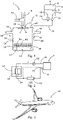
- the 1 shows a system 2 for providing a pressurized liquid.
- the system 2 has a reservoir 4 for receiving the liquid.
- the reservoir 4 is filled with a liquid volume 6, while a residual volume 8 is filled with air.
- An outlet 10 and an inlet 12 are arranged on an underside of the reservoir 4 . Liquid can flow into the reservoir 4 through the inlet 12 . It can be removed from the reservoir 4 again via the outlet 10 .
- An impeller pump 14 is arranged on the outlet 10 as a pressure-increasing device, which is designed to remove liquid from the reservoir 4 and convey it into an inlet line 16 which is connected to an inlet line 18 .
- a first valve 20 is arranged on the inlet 12 and is designed to open in the direction of the reservoir 4 above a certain pressure. It is connected to a drain line 22 .
- the system 2 also has a filter chamber 24 which has an inlet 26 and, for example, two outlets 28 .
- the inlet 26 is connected to the inlet line 18 tied together.
- the inlet line 18 opens centrally and vertically to an upper side 30 in the filter chamber 24 so that liquid from the inlet line 18 is directed towards a center of the filter chamber 24 . This reduces the inflow speed of the liquid.
- a filter insert 32 which has a filter wall 32 is arranged in the filter chamber 24 . This is perforated and extends from the top 30 of the filter chamber 24 to a certain height above a bottom surface 35 of the filter chamber 24, so that an intermediate space 36 below the filter insert 32 remains free.
- a buffer body 38 is arranged there, which has an elastic sleeve 40 which encloses a gas volume 42 .
- the filter chamber 24 has an outer wall 44 which encloses a gap 46 with the outer wall 34 of the filter insert 32 . Liquid that gets into the filter insert 32 through the inlet 26 is fed to the outlets 28 through perforation openings in the filter wall 34 .
- a filter cartridge 48 having an ion exchange resin is arranged on an underside of the filter insert 32 . Liquid can flow through the filter cartridge 48 so that particles are collected there.
- An air separator 49 is arranged on the upper side 30 of the filter chamber 24 .
- the opening of the first valve 20 can also release the air from the filter chamber collected in the air separator 24 discharge. It is conceivable for the impeller pump 14 to be connected to a control unit (not shown), which carries out a pressure increase at predetermined points in time in order therefore to discharge the air in a targeted manner.
- the inlet line 18 is also connected to a bypass line 50 through which the warmer liquid gets into the inlet line 18 and thus into the inlet 26 . This can be used to improve temperature control.
- FIG. 2 12 shows a device 52 with a heat-generating device 54, wherein a heat exchanger 56 is coupled to the heat-generating device 54.
- FIG. A feed pump 58 feeds the liquid from one or both of the outlets 28 of the system 2 through the heat exchanger 56 so that the liquid absorbs heat from the device 52 there.
- the heated liquid flows through a heat dissipation device 60, where it can dissipate heat to the environment. The liquid then flows back into the inlet line 18 of the system.
- the heat emission device can be at least partially bypassed by a connection to the bypass line 50 .
- the corresponding connecting line is drawn as a dashed line.
- the device 54 could be a fuel cell system, for example.
- FIG 3 shows an aircraft 62 in which a device 52 as in 2 shown and/or a system 2 as in 1 shown is arranged.
Landscapes
- Engineering & Computer Science (AREA)
- Chemical & Material Sciences (AREA)
- Chemical Kinetics & Catalysis (AREA)
- Physics & Mathematics (AREA)
- General Chemical & Material Sciences (AREA)
- Life Sciences & Earth Sciences (AREA)
- Manufacturing & Machinery (AREA)
- Sustainable Development (AREA)
- Sustainable Energy (AREA)
- Electrochemistry (AREA)
- General Engineering & Computer Science (AREA)
- Mechanical Engineering (AREA)
- Automation & Control Theory (AREA)
- General Physics & Mathematics (AREA)
- Fluid Mechanics (AREA)
- Thermal Sciences (AREA)
- Analytical Chemistry (AREA)
- Health & Medical Sciences (AREA)
- General Health & Medical Sciences (AREA)
- Pulmonology (AREA)
- Aviation & Aerospace Engineering (AREA)
- Fuel Cell (AREA)
Abstract
Description
- Die Erfindung betrifft ein System zum Bereitstellen einer druckbeaufschlagten Flüssigkeit, eine Vorrichtung mit einer wärmeerzeugenden Einrichtung sowie ein Flugzeug.
- Zur Kühlung von technischen Vorrichtungen werden unter anderem Kühlsysteme mit einem flüssigen Kühlmittel eingesetzt. Das Kühlmittel wird dabei von einer Kühlmittelquelle bereitgestellt und einem mit der Vorrichtung in Kontakt stehenden Wärmetauscher zugeführt, sodass er dort Wärme aufnimmt. Anschließend wird die Flüssigkeit nach Durchlaufen einer geeigneten Wärmeabgabevorrichtung wieder der Kühlmittelquelle zugeführt. Durch ungleichmäßige Temperaturänderungen der Flüssigkeit ist mit Dichte- bzw. Volumenänderungen zu rechnen, die in einem geschlossenen Kühlkreislauf ausgeglichen werden müssen. Dies kann beispielsweise durch einen in dem Kühlkreislauf angeordneten Expansionstank erreicht werden.
- Bekannte Expansionstanks weisen einen Behälter mit einer Membran auf. Ein Teil des Volumens des Behälters wird mit Gas befüllt, das sich bis zu der Membran erstreckt. Auf der anderen Seite der Membran befindet sich die Flüssigkeit innerhalb des Behälters. Das Gas gewährleistet einen minimalen Druck in dem Kühlsystem und durch den Expansionstank können sehr leicht Volumenänderungen ausgeglichen werden.
- Bei der Kühlung von Brennstoffzellen oder anderen empfindlichen Vorrichtungen ist allerdings ein Maximaldruck des Kühlmittels begrenzt. Die technische Umsetzung einer solchen Begrenzung würde jedoch einen sehr großen Expansionstank erfordern, der gerade bei kompakter Bauweise zu vermeiden ist. Mit bekannten Expansionstanks, insbesondere bei der Verwendung für Brennstoffzellen, die in Verkehrsmitteln eingesetzt werden, kann nicht gleichzeitig ein Maximaldruck begrenzt und ein Bauraum minimiert werden.
- Es ist folglich eine Aufgabe der Erfindung, ein System zum Bereitstellen einer druckbeaufschlagten Flüssigkeit vorzuschlagen, bei dem ein Mindestdruck garantiert und ein statischer Druck durch Dichteänderung minimiert werden kann, wobei gleichzeitig der Bauraum so kompakt wie möglich sein sollte.
- Die Aufgabe wird gelöst durch ein System mit den Merkmalen des unabhängigen Anspruchs 1. Vorteilhafte Ausführungsformen und Weiterbildungen sind den Unteransprüchen und der nachfolgenden Beschreibung zu entnehmen.
- Es wird ein System zum Bereitstellen einer druckbeaufschlagten Flüssigkeit vorgeschlagen, aufweisend ein Reservoir zum Aufnehmen der Flüssigkeit mit einem Ablauf und einem Zulauf, eine Druckerhöhungseinrichtung, ein erstes Ventil, eine separate Filterkammer mit einem Einlass und mindestens einem Auslass, und einen kompressiblen, geschlossenen Pufferkörper, wobei die Druckerhöhungseinrichtung mit der Filterkammer gekoppelt ist und dazu ausgebildet ist, einen Druck der Flüssigkeit innerhalb der Filterkammer zu erhöhen, wobei das erste Ventil zwischen dem Zulauf des Reservoirs und der Filterkammer angeordnet ist und dazu ausgebildet ist, bei Erreichen oder Überschreiten eines Mindestdrucks der Flüssigkeit in der Filterkammer in Richtung des Reservoirs zu öffnen, und wobei der Pufferkörper in der Filterkammer angeordnet ist, sodass er von Flüssigkeit umgebbar ist.
- Das Reservoir ist als ein eigenständiger Behälter mit einem bestimmten Aufnahmevolumen zu verstehen. Die Flüssigkeit kann über den Zulauf in das Aufnahmevolumen eintreten und dieses durch den Ablauf wieder verlassen. Das Reservoir ist nicht druckdicht geschlossen, sodass es sehr einfach in der Lage ist, eine variable Flüssigkeitsmenge aufzunehmen. Ein Restvolumen des Reservoirs ist mit Luft gefüllt, wobei das Restvolumen bevorzugt mit der Umgebung des Reservoirs in Fluidkontakt steht, um ein rasches Ein- bzw. Ausströmen zu erlauben. Das Reservoir könnte auch an anderen Stellen mit dem System verbunden sein.
- Die Filterkammer ist als ein zumindest weitgehend geschlossener Behälter zu verstehen. Über den Einlass kann Flüssigkeit in die Filterkammer treten und aus dem mindestens einen Auslass wieder herausströmen, um Kühlaufgaben oder anderes wahrzunehmen. Die Filterkammer kann eine Einrichtung zum Filtern von Fremdkörpern aus der Flüssigkeit aufweisen, wie weiter nachfolgend im Detail erläutert.
- Die Druckerhöhungseinrichtung kann als eine Pumpe ausgeführt sein, welche Flüssigkeit über den Ablauf aus dem Reservoir entnehmen kann, sie in die Filterkammer fördert und so den darin befindlichen Druck erhöhen kann. Alternativ dazu kann auch ein anderes Medium den Druck in dem Reservoir erhöhen, beispielsweise druckbeaufschlagte Luft, welche von einer entsprechenden Quelle in einer Entlüftungsöffnung des Reservoirs bereitstellbar ist. Die Quelle könnte etwa ein Luftzufuhrsystem für eine Brennstoffzelle sein. Zum Begrenzen des Drucks ist das erste Ventil vorgesehen, das bei einem vorgegebenen Mindestdruck öffnet und Flüssigkeit aus der Filterkammer in das Reservoir zurückströmen lässt. Der Mindestdruck ist derart vorgegeben, dass die vorgesehene Kühlanwendung auch an einer empfindlichen Vorrichtung sicher erfüllt wird, ohne einen vorgegebenen Druck zu überschreiten. Das erste Ventil könnte ein Rückschlagventil, ein steuerbares Ventil in Verbindung mit einem Drucksensor oder eine ähnliche Ventilkonstruktion aufweisen.
- Der Pufferkörper in der Filterkammer wird durch den auf ihn einwirkenden Druck der Flüssigkeit komprimiert, sodass sich sein Volumen mit steigendem Druck verringert. Folglich wird das durch die Flüssigkeit einnehmbare, freie Volumen in der Filterkammer mit steigendem Druck vergrößert, sodass sehr effektiv Druckspitzen und andere Druckschwankungen vermieden werden können. Der Pufferkörper puffert bzw. vergleichmäßigt den Druck in der Filterkammer auch bei unterschiedlichen Volumenströmen über dem Einlass und dem mindestens einen Auslass und über verschiedene Betriebszustände der Druckerhöhungseinrichtung.
- Die Verwendung der separaten Filterkammer, die bevorzugt ohnehin bereits für die Filterfunktion in einem Kühlkreislauf vorgesehen sein kann, erlaubt die Nutzung eines bereits vorhandenen, jedoch üblicherweise nur zum Filtern vorgesehenen Volumens zum Ausgleich von Dichteänderungen der Flüssigkeit, ohne den Bauraum des Kühlsystems oder einer anderen Anwendung insgesamt zu erhöhen. Mit optimierter Auslegung des Volumens des Reservoirs könnte sogar eine Verringerung des gesamten Bauraums erreicht werden.
- In einer vorteilhaften Ausführungsform umfasst die Filterkammer einen Filtereinsatz, der eine perforierte Filterwandung aufweist, die in einem Abstand zu einer Außenwandung der Filterkammer verläuft. Der Filtereinsatz wird folglich im Wesentlichen durch eine Filterwandung gebildet, die in einem vorbestimmten Abstand zu einer Außenwandung der Filterkammer verläuft und für die Flüssigkeit durchlässig ist. Der Abstand zwischen der Außenwandung und der Filterwandung könnte derart dimensioniert sein, dass ein Spalt zwischen beiden verbleibt, in dem sich Flüssigkeit ungehindert ausbreiten und von dort leicht durch die Filterwandung fließen kann. Der Lochanteil der Perforation der Filterwandung ist bevorzugt so gewählt, dass der Filtereinsatz zu einem möglichst geringen zusätzlichen Strömungswiderstand führt. Die Perforationsöffnungen können eine Öffnungsweise im Mikrometerbereich aufweisen.
- Der Einlass der Filterkammer mündet bevorzugt in dem Inneren des Filtereinsatzes, wobei der mindestens eine Auslass in der Außenwandung der Filterkammer angeordnet ist. Flüssigkeit, die über den Einlass in die Filterkammer gerät, strömt folglich direkt in den Filtereinsatz. Aus der Filterkammer ausströmende Flüssigkeit strömt indes aus einem Spalt zwischen dem Filtereinsatz und der Außenwandung heraus und wurde folglich durch die Filterwandung gefiltert.
- In einer vorteilhaften Ausführungsform ist eine Filterkartusche in der Filterkammer in einem von dem Einlass abgewandten Bereich angeordnet. Die Filterkartusche kann eine zusätzliche Aufnahme bzw. Sammlung von Partikeln und anderen Fremdkörpern erreichen. Sie kann so platziert werden, dass in die Filterkammer einströmende Flüssigkeit zu der Filterkartusche gerät, um dort gefiltert wieder auszutreten. Sie könnte etwa direkt gegenüber des Einlasses angeordnet sein, beispielsweise im Bereich eines Bodens der Filterkammer, während der Einlass an einer Oberseite der Filterkammer angeordnet sein kann. Die Filterkartusche kann getrennt oder zusammen mit dem Filtereinsatz als ein austauschbares Element vorgesehen werden.
- Es ist bevorzugt, wenn die Filterkartusche ein Ionenaustauschharz aufweist. Dies ist ein Material, welches als Medium für den Ionenaustausch dient. Es ist als eine unlösliche Matrix realisiert, die etwa in Form kleiner Mikrokügelchen aus einem organischen Polymersubstrat ausgebildet ist. Die Mikrokügelchen sind bevorzugt porös und weisen eine große Oberfläche auf, auf der und in der das Einfangen von Ionen zusammen mit der begleitenden Freisetzung anderer Ionen stattfindet.
- In einer weiter vorteilhaften Ausführungsform ist der Pufferkörper außerhalb des Filtereinsatzes in der Filterkammer angeordnet. Der Pufferkörper wird folglich nicht direkt mit einer Flüssigkeitsströmung beaufschlagt. Zwischen dem Filtereinsatz und der Außenwandung der Filterkammer kann ein geeigneter Bereich ausgebildet werden, in dem der Pufferkörper angeordnet werden kann. Dieser Raum ist dabei bevorzugt so zu dimensionieren, dass auch bei Umgebungsdruck und dem daraus folgenden größten Volumen des Pufferkörpers sich dieser dort frei anordnen lässt.
- Das System kann ferner einen Luftseparator aufweisen, der an einem oberen Ende der Filterkammer angeordnet ist und dazu ausgebildet ist, Luft aus der Filterkammer nach außen zu leiten. Der Luftseparator ist vorgesehen, um Luft aus der Filterkammer nach außen zu führen. Bei der Druckbeaufschlagung der Flüssigkeit und den dort vorzufindenden Strömungsbedingungen kann nicht ausgeschlossen werden, dass Luftbläschen in der Flüssigkeit vorliegen. Diese können in der Filterkammer entgegen der Schwerkraft nach oben treiben und dort in dem Luftseparator landen. Aus diesem können sie nach außen geführt werden.
- Besonders bevorzugt ist das erste Ventil mit dem Luftseparator verbunden. Die Luftbläschen geraten daher aus dem Luftseparator durch das erste Ventil in das Reservoir, wo sie ebenso gegen die Schwerkraft nach oben treiben und sich in dem Restvolumen des Reservoirs ansammeln bzw. von dort in die Umgebung austreten. Zum gezielten Heraustreiben von Luftbläschen kann vorgesehen sein, die Druckerhöhungseinrichtung auch bei ausreichendem Druck in der Filterkammer zu betreiben, sodass der Druck so weit erhöht wird, dass das erste Ventil öffnet. Dann wird gezielt über den Luftseparator Luft nach außen geleitet.
- Es könnte sich ein Luftfilter an einer Öffnung des Luftseparators und/oder des Reservoirs befinden, um das Eindringen von Partikeln von außen zu vermeiden.
- In einer weiter vorteilhaften Ausführungsform ist der Einlass in einer oberen Begrenzungsfläche der Filterkammer angeordnet und in ein Zentrum der Filterkammer gerichtet. Die obere Begrenzungsfläche wird weiter nachfolgend auch Oberseite genannt. Durch diese Anordnung kann die einströmende Flüssigkeit abgebremst und großflächig durch die Filterkammer gefiltert werden.
- Es ist vorteilhaft, wenn der Einlass mit einer Einlassleitung verbunden ist, wobei eine Bypassleitung mit der Einlassleitung verbunden ist. Die Bypassleitung könnte für eine Temperaturregelung eingesetzt werden. Beispielsweise kann in einem Kühlkreislauf ein Wärmetauscher vorgesehen sein, über den Wärme aus dem Kühlkreislauf nach außen abgegeben wird. Über einen Bypass kann der Wärmetauscher von einem Teil der Strömung umgangen werden, etwa um eine Temperatur in dem Kühlkreislauf zu erhöhen bzw. den Wärmeabtransport temporär zu reduzieren. Dies kann besonders sinnvoll sein, wenn das System mit einem Kühlsystem für eine Brennstoffzelle gekoppelt ist und die Brennstoffzelle hochgefahren und auf eine Betriebstemperatur gebracht werden muss.
- Eine Bypassleitung könnte jedoch auch separat und direkt mit einer Begrenzungsfläche der Filterkammer verbunden sein und dort in einer entsprechenden Öffnung münden.
- In einer vorteilhaften Ausführungsform ist die Druckerhöhungseinrichtung mit der Einlassleitung verbunden. Die Filterkammer erfordert aus diesem Grunde keinen zusätzlichen Einlass zum direkten Anschluss der Druckerhöhungseinrichtung, sondern sämtliche Flüssigkeitsquellen können über einen einzigen Einlass gesammelt in die Filterkammer geleitet werden.
- Der Pufferkörper könnte eine elastische Hülle aufweisen, die ein Gasvolumen umschließt. Das Gasvolumen dient als federndes, kompressibles Element. Die Hülle könnte aus einem gummiartigen Element ausgebildet sein.
- Besonders bevorzugt ist die Druckerhöhungseinrichtung eine Pumpe, insbesondere eine Impellerpumpe. Eine solche ist üblicherweise selbstansaugend und ist dafür geeignet, auch niedrigviskose Flüssigkeiten zu fördern. Es wäre auch denkbar, neben einer Pumpe zusätzlich druckbeaufschlagte Luft zu verwenden, wie weiter vorangehend beschrieben. Damit kann eine Redundanz erreicht werden.
- Die Erfindung betrifft ferner eine Vorrichtung mit einer wärmeerzeugenden Einrichtung, einem mit der wärmeerzeugenden Einrichtung thermisch gekoppelten Wärmetauscher und einem System gemäß der vorhergehenden Beschreibung, wobei das System mit dem Wärmetauscher verbunden ist, sodass Flüssigkeit von dem System bereitgestellt und durch den Wärmetauscher förderbar ist. Die wärmeerzeugende Einrichtung könnte insbesondere ein Brennstoffzellensystem sein, das einen oder mehrere Brennstoffzellenstapel mit einzelnen Brennstoffzellen aufweist, welche eine Vielzahl von Kühlmittelkanälen aufweist. Diese können in Bipolarplatten oder direkt daran angrenzend angeordnet sein und werden von dem System mit der Flüssigkeit in Form eines Kühlmittels durchströmt. Hierzu ist eine Förderpumpe vorgesehen, die mit dem mindestens einen Auslass in Verbindung steht.
- Schließlich betrifft die Erfindung ein Flugzeug, welches mindestens eine vorangehend genannte Vorrichtung und/oder ein vorangehend genanntes System aufweist.
- Weitere Merkmale, Vorteile und Anwendungsmöglichkeiten der vorliegenden Erfindung ergeben sich aus der nachfolgenden Beschreibung der Ausführungsbeispiele und den Figuren. Dabei bilden alle beschriebenen und/oder bildlich dargestellten Merkmale für sich und in beliebiger Kombination den Gegenstand der Erfindung auch unabhängig von ihrer Zusammensetzung in den einzelnen Ansprüchen oder deren Rückbezügen. In den Figuren stehen weiterhin gleiche Bezugszeichen für gleiche oder ähnliche Objekte.
-
Fig. 1 zeigt eine schematische Darstellung des erfindungsgemäßen Systems. -
Fig. 2 zeigt eine schematische Ansicht einer Vorrichtung mit einer wärmeerzeugenden Einrichtung, die mit dem erfindungsgemäßen System gekoppelt ist. -
Fig. 3 zeigt ein Flugzeug. -
Fig. 1 zeigt ein System 2 zum Bereitstellen einer druckbeaufschlagten Flüssigkeit. Das System 2 weist ein Reservoir 4 zum Aufnehmen der Flüssigkeit auf. Das Reservoir 4 ist in dieser Darstellung mit einem Flüssigkeitsvolumen 6 gefüllt, während ein Restvolumen 8 mit Luft gefüllt ist. An einer Unterseite des Reservoirs 4 sind ein Ablauf 10 und ein Zulauf 12 angeordnet. Durch den Zulauf 12 kann Flüssigkeit in das Reservoir 4 einströmen. Über den Ablauf 10 kann es dem Reservoir 4 wieder entnommen werden. - An dem Ablauf 10 ist eine Impellerpumpe 14 als Druckerhöhungseinrichtung angeordnet, die dazu ausgebildet ist, Flüssigkeit aus dem Reservoir 4 zu entnehmen und in eine Zulaufleitung 16 zu fördern, die mit einer Einlassleitung 18 verbunden ist. An den Zulauf 12 ist ein erstes Ventil 20 angeordnet, das dazu ausgebildet ist, ab einem bestimmten Druck in Richtung des Reservoirs 4 zu öffnen. Es ist mit einer Ablaufleitung 22 verbunden.
- Das System 2 weist ferner eine Filterkammer 24 auf, die einen Einlass 26 und beispielhaft zwei Auslässe 28 aufweist. Der Einlass 26 ist mit der Einlassleitung 18 verbunden. Die Einlassleitung 18 mündet in dieser Darstellung mittig und vertikal zu einer Oberseite 30 in der Filterkammer 24, sodass Flüssigkeit aus der Einlassleitung 18 in Richtung eines Zentrums der Filterkammer 24 gerichtet ist. Dadurch wird die Einströmgeschwindigkeit der Flüssigkeit reduziert.
- In der Filterkammer 24 ist ein Filtereinsatz 32 angeordnet, der eine Filterwandung 32 besitzt. Diese ist perforiert und erstreckt sich von der Oberseite 30 der Filterkammer 24 bis zu einer bestimmten Höhe über einer Bodenfläche 35 der Filterkammer 24, sodass ein Zwischenraum 36 unterhalb des Filtereinsatzes 32 frei bleibt. Dort ist ein Pufferkörper 38 angeordnet, welcher eine elastische Hülle 40 besitzt, die ein Gasvolumen 42 umschließt. Die Filterkammer 24 weist eine Außenwandung 44 auf, die mit der Außenwandung 34 des Filtereinsatzes 32 einen Spalt 46 einschließt. Flüssigkeit, die durch den Einlass 26 in den Filtereinsatz 32 gerät, wird durch Perforationsöffnungen in der Filterwandung 34 den Auslässen 28 zugeführt.
- An einer Unterseite des Filtereinsatzes 32 ist eine Filterkartusche 48 angeordnet, die ein Ionenaustauscherharz aufweist. Flüssigkeit kann die Filterkartusche 48 durchströmen, sodass Partikel dort gesammelt werden.
- An der Oberseite 30 der Filterkammer 24 ist ein Luftseparator 49 angeordnet. Dieser könnte ein ringförmiger Sammelbehälter sein, der in Richtung der Bodenfläche 35 zumindest bereichsweise offen ist. Luftbläschen, die in der Filterkammer 24 vorliegen und schwerkraftbedingt zu der Oberseite 30 wandern, gelangen in den Luftseparator 49. Dieser ist mit der Ablaufleitung 22 verbunden und kann folglich über das erste Ventil 20 in das Reservoir 4 geraten. Wird die Impellerpumpe 14 betrieben, wird der Druck innerhalb der Filterkammer 24 erhöht. Beim Erreichen eines bestimmten Drucks öffnet das erste Ventil 20, sodass der Druck in der Filterkammer 24 hierdurch begrenzt wird. Dadurch kann ein maximal Druck innerhalb der Filterkammer 24 gewährleistet werden. Das Öffnen des ersten Ventils 20 kann jedoch auch die in dem Luftseparator gesammelte Luft aus der Filterkammer 24 abführen. Es ist vorstellbar, die Impellerpumpe 14 mit einer Steuereinheit (nicht gezeigt) zu verbinden, die zu vorgegebenen Zeitpunkten eine Druckerhöhung durchführt, um daher jeweils die Luft gezielt abzuführen.
- Die Einlassleitung 18 ist weiterhin mit einer Bypassleitung 50 verbunden, durch die wärmere Flüssigkeit in die Einlassleitung 18 und damit den Einlass 26 gerät. Dies kann zur Verbesserung der Temperaturregelung eingesetzt werden.
-
Fig. 2 zeigt eine Vorrichtung 52 mit einer wärmeerzeugenden Einrichtung 54, wobei ein Wärmetauscher 56 mit der Wärme erzeugenden Einrichtung 54 gekoppelt ist. Eine Förderpumpe 58 fördert die Flüssigkeit aus einem oder beiden der Auslässe 28 des Systems 2 durch den Wärmetauscher 56, sodass die Flüssigkeit dort Wärme der Vorrichtung 52 aufnimmt. Im weiteren Verlauf strömt die erwärmte Flüssigkeit durch eine Wärmeabgabeeinrichtung 60, wo sie Wärme an die Umgebung abgeben kann. Anschließend strömt die Flüssigkeit zurück in die Einlassleitung 18 des Systems. Ist gewünscht, die Einrichtung 54 auf eine Betriebstemperatur zu bringen und anschließend durch Kühlung die Betriebstemperatur zu halten, kann die Wärmeabgabeeinrichtung durch eine Verbindung mit der Bypassleitung 50 zumindest teilweise umgangen werden. Die entsprechende Verbindungslinie ist gestrichelt gezeichnet. Es könnte dort ein steuerbares zweites Ventil vorliegen und gegebenenfalls ein Rückschlagventil. Die Einrichtung 54 könnte beispielsweise ein Brennstoffzellensystem sein. -
Fig. 3 zeigt ein Flugzeug 62, in dem eine Vorrichtung 52 wie inFig. 2 gezeigt und/oder ein System 2 wie inFig. 1 gezeigt angeordnet ist. - Ergänzend sei darauf hingewiesen, dass "aufweisend" keine anderen Elemente oder Schritte ausschließt, und "ein" oder "eine" keine Vielzahl ausschließt. Ferner sei darauf hingewiesen, dass Merkmale, die mit Verweis auf eines der obigen Ausführungsbeispiele beschrieben worden sind, auch in Kombination mit anderen Merkmalen anderer oben beschriebener Ausführungsbeispiele verwendet werden können. Bezugszeichen in den Ansprüchen sind nicht als Einschränkung anzusehen.
-
- 2
- System
- 4
- Reservoir
- 6
- Flüssigkeitsvolumen
- 8
- Restvolumen
- 10
- Ablauf
- 12
- Zulauf
- 14
- Druckerhöhungseinrichtung / Impellerpumpe
- 16
- Zulaufleitung
- 18
- Einlassleitung
- 20
- erstes Ventil
- 22
- Ablaufleitung
- 24
- Filterkammer
- 26
- Einlass
- 28
- Auslass
- 30
- Oberseite / obere Begrenzungsfläche
- 32
- Filtereinsatz
- 34
- Filterwandung
- 35
- Bodenfläche
- 36
- Zwischenraum
- 38
- Pufferkörper
- 40
- elastische Hülle
- 42
- Gasvolumen
- 44
- Außenwandung
- 46
- Spalt
- 48
- Filterkartusche
- 49
- Luftseparator
- 50
- Bypassleitung
- 52
- Vorrichtung
- 54
- wärmeerzeugende Einrichtung
- 56
- Wärmetauscher
- 58
- Förderpumpe
- 60
- Wärmeabgabeeinrichtung
- 62
- Flugzeug
Claims (15)
- System (2) zum Bereitstellen einer druckbeaufschlagten Flüssigkeit, aufweisend:- ein Reservoir (4) zum Aufnehmen der Flüssigkeit mit einem Ablauf (10) und einem Zulauf (12),- eine Druckerhöhungseinrichtung (14),- ein erstes Ventil (20),- eine separate Filterkammer (24) mit einem Einlass (26) und mindestens einem Auslass (28), und- einen kompressiblen, geschlossenen Pufferkörper (38),wobei die Druckerhöhungseinrichtung (14) mit der Filterkammer (24) gekoppelt ist und dazu ausgebildet ist, einen Druck der Flüssigkeit innerhalb der Filterkammer (24) zu erhöhen,wobei das erste Ventil (20) zwischen dem Zulauf (12) des Reservoirs (4) und der Filterkammer (24) angeordnet ist und dazu ausgebildet ist, bei Erreichen oder Überschreiten eines Mindestdrucks der Flüssigkeit in der Filterkammer (24) in Richtung des Reservoirs (4) zu öffnen, undwobei der Pufferkörper (38) in der Filterkammer (24) angeordnet ist, sodass er von Flüssigkeit umgebbar ist.
- System (2) nach Anspruch 1,
wobei die Filterkammer (24) einen Filtereinsatz (32) umfasst, der eine perforierte Filterwandung (34) aufweist, die in einem Abstand zu einer Außenwandung (44) der Filterkammer (24) verläuft. - System (2) nach Anspruch 2,
wobei der Einlass (26) der Filterkammer (24) in dem Inneren des Filtereinsatzes (32) mündet und der mindestens eine Auslass (28) in der Außenwandung (44) der Filterkammer (24) angeordnet ist. - System (2) nach einem der vorhergehenden Ansprüche,
wobei eine Filterkartusche (48) in der Filterkammer (24) in einem von dem Einlass (26) abgewandten Bereich angeordnet ist. - System (2) nach Anspruch 4,
wobei die Filterkartusche (48) ein Ionenaustauschharz aufweist. - System (2) nach Anspruch 2,
wobei der Pufferkörper (38) außerhalb des Filtereinsatzes (32) in der Filterkammer (24) angeordnet ist. - System (2) nach einem der vorhergehenden Ansprüche,
ferner aufweisend einen Luftseparator (49), der an einem oberen Ende der Filterkammer (24) angeordnet ist, und der dazu ausgebildet ist, Luft aus der Filterkammer (24) nach außen zu leiten. - System (2) nach Anspruch 7,
wobei das erste Ventil (20) mit dem Luftseparator (49) verbunden ist. - System (2) nach einem der vorhergehenden Ansprüche,
wobei der Einlass (26) in einer oberen Begrenzungsfläche (30) der Filterkammer (24) angeordnet und in ein Zentrum der Filterkammer (24) gerichtet ist. - System (2) nach einem der vorhergehenden Ansprüche,wobei der Einlass (26) mit einer Einlassleitung (18) verbunden ist, undwobei eine Bypassleitung (50) mit der Einlassleitung (18) verbunden ist.
- System (2) nach Anspruch 10,
wobei die Druckerhöhungseinrichtung (14) mit der Einlassleitung (18) verbunden ist. - System (2) nach einem der vorhergehenden Ansprüche,
wobei der Pufferkörper (38) eine elastische Hülle (40) aufweist, die ein Gasvolumen (42) umschließt. - System (2) nach einem der vorhergehenden Ansprüche,
wobei die Druckerhöhungseinrichtung (14) eine Pumpe, insbesondere eine Impellerpumpe (14) ist. - Vorrichtung (52) mit einer wärmeerzeugenden Einrichtung (54), einem mit der wärmeerzeugenden Einrichtung (54) thermisch gekoppelten Wärmetauscher (56) und einem System (2) nach einem der vorhergehenden Ansprüche, wobei das System (2) mit dem Wärmetauscher (56) verbunden ist, sodass Flüssigkeit von dem System (2) bereitgestellt und durch den Wärmetauscher (56) förderbar ist.
- Flugzeug (62), aufweisend mindestens eine Vorrichtung nach Anspruch 14 und/oder mindestens ein System (2) nach einem der Ansprüche 1 bis 13.
Applications Claiming Priority (1)
| Application Number | Priority Date | Filing Date | Title |
|---|---|---|---|
| DE102021102107.3A DE102021102107A1 (de) | 2021-01-29 | 2021-01-29 | System zum Bereitstellen einer druckbeaufschlagten Flüssigkeit |
Publications (2)
| Publication Number | Publication Date |
|---|---|
| EP4036512A1 true EP4036512A1 (de) | 2022-08-03 |
| EP4036512B1 EP4036512B1 (de) | 2023-11-22 |
Family
ID=82199333
Family Applications (1)
| Application Number | Title | Priority Date | Filing Date |
|---|---|---|---|
| EP22153381.3A Active EP4036512B1 (de) | 2021-01-29 | 2022-01-26 | System zum bereitstellen einer druckbeaufschlagten flüssigkeit |
Country Status (3)
| Country | Link |
|---|---|
| US (1) | US12076672B2 (de) |
| EP (1) | EP4036512B1 (de) |
| DE (1) | DE102021102107A1 (de) |
Citations (5)
| Publication number | Priority date | Publication date | Assignee | Title |
|---|---|---|---|---|
| EP0536470A1 (de) * | 1991-10-08 | 1993-04-14 | Firma Carl Freudenberg | Verdampfungsgekühlte Verbrennungskraftmaschine |
| US6171718B1 (en) * | 1998-12-28 | 2001-01-09 | International Fuel Cells, Llc | Pressurized water recovery system for a fuel cell power plant |
| US20100154467A1 (en) * | 2006-01-17 | 2010-06-24 | Shuuji Fujimoto | Gas-Liquid Separator and Refrigeration System With Gas-Liquid Seperator |
| US20160036071A1 (en) * | 2014-07-30 | 2016-02-04 | Airbus Operations Gmbh | Cooling concept for a fuel cell system for a vehicle and aircraft having such a fuel cell system |
| DE112014006218T5 (de) * | 2014-01-21 | 2016-11-03 | Denso Corporation | Wärmepumpenkreislaufvorrichtung |
Family Cites Families (8)
| Publication number | Priority date | Publication date | Assignee | Title |
|---|---|---|---|---|
| US3834535A (en) | 1972-08-09 | 1974-09-10 | Diaclear Inc | Swimming pool filtering system |
| FR2275663A2 (fr) * | 1974-06-21 | 1976-01-16 | Vergnet Marc | Pompe perfectionnee |
| US4806135A (en) * | 1988-03-01 | 1989-02-21 | Siposs George G | Bubble trap for phase-separating gas bubbles from flowing liquids |
| US6328071B1 (en) * | 1993-08-06 | 2001-12-11 | Cary Austin | Well pressure tank |
| CA2122165A1 (fr) * | 1994-04-26 | 1995-10-27 | Reginald Cormier | Recuperateur d'eau domestique pour usage de toilette |
| ATE306305T1 (de) * | 2002-03-18 | 2005-10-15 | Parker Hannifin Corp | Mobiler tankfilter und filteranordnung |
| US7013924B1 (en) * | 2003-11-17 | 2006-03-21 | In-Well Technologies Inc. | Fluid pressure system including free floating bladder |
| RU2014124001A (ru) * | 2011-11-16 | 2015-12-27 | Байер Интеллектуэль Проперти Гмбх | Устройство для фильтрации, сушки и хранения твердых веществ из суспензии |
-
2021
- 2021-01-29 DE DE102021102107.3A patent/DE102021102107A1/de active Pending
-
2022
- 2022-01-26 EP EP22153381.3A patent/EP4036512B1/de active Active
- 2022-01-28 US US17/587,049 patent/US12076672B2/en active Active
Patent Citations (5)
| Publication number | Priority date | Publication date | Assignee | Title |
|---|---|---|---|---|
| EP0536470A1 (de) * | 1991-10-08 | 1993-04-14 | Firma Carl Freudenberg | Verdampfungsgekühlte Verbrennungskraftmaschine |
| US6171718B1 (en) * | 1998-12-28 | 2001-01-09 | International Fuel Cells, Llc | Pressurized water recovery system for a fuel cell power plant |
| US20100154467A1 (en) * | 2006-01-17 | 2010-06-24 | Shuuji Fujimoto | Gas-Liquid Separator and Refrigeration System With Gas-Liquid Seperator |
| DE112014006218T5 (de) * | 2014-01-21 | 2016-11-03 | Denso Corporation | Wärmepumpenkreislaufvorrichtung |
| US20160036071A1 (en) * | 2014-07-30 | 2016-02-04 | Airbus Operations Gmbh | Cooling concept for a fuel cell system for a vehicle and aircraft having such a fuel cell system |
Also Published As
| Publication number | Publication date |
|---|---|
| US20220241706A1 (en) | 2022-08-04 |
| DE102021102107A1 (de) | 2022-08-04 |
| EP4036512B1 (de) | 2023-11-22 |
| US12076672B2 (en) | 2024-09-03 |
Similar Documents
| Publication | Publication Date | Title |
|---|---|---|
| DE69225849T2 (de) | Flüssigkeitsbehälter, damit versehener Aufzeichnungskopf und zugehöriges Aufzeichnungsgerät | |
| DE102008018276B4 (de) | Brennstoffzellensystem mit einem geschlossenen Kühlmittelkreislauf und dessen Verwendung | |
| DE102014225120B4 (de) | Thermo-Managementsystem für Brennstoffzellenfahrzeuge | |
| DE102022107488A1 (de) | Batterie mit einem als Bypass zuschaltbaren Kühlelement und Verfahren zum Kühlen eines in der Batterie erzeugten Gases | |
| DE102005017648A1 (de) | Flüssigkeitsgekühlte Batterie und Verfahren zum Betreiben einer solchen | |
| EP3560016B1 (de) | Brennstoffzuführanordnung für ein brennstoffzellensystem und brennstoffzellensystem | |
| EP3521584A1 (de) | Ausgleichsbehälter für kühlkreisläufe mit unterschiedlichem temperaturniveau und druckaddition | |
| DE102019204270A1 (de) | Flüssigkeitsgekühlte Energiespeicheranordnung | |
| EP3133353B1 (de) | Wasserfilterpatrone mit luftführung | |
| DE102007003828B4 (de) | Kühlmittelreservoiranordnung und multifunktionale Einheit für ein Kühlmittelreservoir | |
| DE10318949B4 (de) | Druckpatrone | |
| DE102023106587A1 (de) | Vorrichtung zur Druckregelung und Entgasung eines Kühlmediums und Kühlkreislauf | |
| EP4036512B1 (de) | System zum bereitstellen einer druckbeaufschlagten flüssigkeit | |
| EP3927615A1 (de) | Auftriebsmodifikationsmodul für ein modulares unterwasserfahrzeug | |
| EP3611787A2 (de) | Brennstoffzellensystem für ein luftfahrzeug | |
| DE102020005166A1 (de) | Batterie mit einem Gehäuse | |
| DE102018205876A1 (de) | Kühlvorrichtung für eine Batterie, Kraftfahrzeug und Verfahren zum Kühlen einer Batterie | |
| DE3320197A1 (de) | Gaserzeugungsanlage, insbesondere fuer unterwasserfahrzeuge | |
| DE102020004533A1 (de) | Flüssigkeitsabscheider | |
| DE102021116769B4 (de) | Fluidablaufanordnung für eine Batterieanordnung | |
| DE1571960B1 (de) | Verfahren zum umwaelzen eines fluessigen elektrolyten in einer galvanischen zelle zb einer brennstoffzelle und anord nung zur durchfuehrung des verfahrens | |
| EP2645461A1 (de) | Kühlkreislauf zum Kühlen einer elektrochemischen Zelle sowie Verfahren zum Betreiben eines solchen Kühlkreislaufs | |
| DE102021208485A1 (de) | Vorrichtung zum Druckausgleich | |
| DE102013201332A1 (de) | Kühlsystem einer Fahrzeugbatterie | |
| DE102024002409B3 (de) | Batteriemodul, Batterie und Verfahren zum Betreiben der Batterie |
Legal Events
| Date | Code | Title | Description |
|---|---|---|---|
| PUAI | Public reference made under article 153(3) epc to a published international application that has entered the european phase |
Free format text: ORIGINAL CODE: 0009012 |
|
| STAA | Information on the status of an ep patent application or granted ep patent |
Free format text: STATUS: THE APPLICATION HAS BEEN PUBLISHED |
|
| AK | Designated contracting states |
Kind code of ref document: A1 Designated state(s): AL AT BE BG CH CY CZ DE DK EE ES FI FR GB GR HR HU IE IS IT LI LT LU LV MC MK MT NL NO PL PT RO RS SE SI SK SM TR |
|
| STAA | Information on the status of an ep patent application or granted ep patent |
Free format text: STATUS: REQUEST FOR EXAMINATION WAS MADE |
|
| 17P | Request for examination filed |
Effective date: 20230203 |
|
| RBV | Designated contracting states (corrected) |
Designated state(s): AL AT BE BG CH CY CZ DE DK EE ES FI FR GB GR HR HU IE IS IT LI LT LU LV MC MK MT NL NO PL PT RO RS SE SI SK SM TR |
|
| GRAP | Despatch of communication of intention to grant a patent |
Free format text: ORIGINAL CODE: EPIDOSNIGR1 |
|
| STAA | Information on the status of an ep patent application or granted ep patent |
Free format text: STATUS: GRANT OF PATENT IS INTENDED |
|
| INTG | Intention to grant announced |
Effective date: 20230629 |
|
| RIN1 | Information on inventor provided before grant (corrected) |
Inventor name: CASPARI, JANA Inventor name: WARSCH, CHRISTOPHER Inventor name: TRUEMPER, TORSTEN |
|
| GRAS | Grant fee paid |
Free format text: ORIGINAL CODE: EPIDOSNIGR3 |
|
| GRAA | (expected) grant |
Free format text: ORIGINAL CODE: 0009210 |
|
| STAA | Information on the status of an ep patent application or granted ep patent |
Free format text: STATUS: THE PATENT HAS BEEN GRANTED |
|
| AK | Designated contracting states |
Kind code of ref document: B1 Designated state(s): AL AT BE BG CH CY CZ DE DK EE ES FI FR GB GR HR HU IE IS IT LI LT LU LV MC MK MT NL NO PL PT RO RS SE SI SK SM TR |
|
| REG | Reference to a national code |
Ref country code: GB Ref legal event code: FG4D Free format text: NOT ENGLISH |
|
| REG | Reference to a national code |
Ref country code: CH Ref legal event code: EP |
|
| REG | Reference to a national code |
Ref country code: DE Ref legal event code: R096 Ref document number: 502022000266 Country of ref document: DE |
|
| REG | Reference to a national code |
Ref country code: IE Ref legal event code: FG4D Free format text: LANGUAGE OF EP DOCUMENT: GERMAN |
|
| REG | Reference to a national code |
Ref country code: LT Ref legal event code: MG9D |
|
| REG | Reference to a national code |
Ref country code: NL Ref legal event code: MP Effective date: 20231122 |
|
| PG25 | Lapsed in a contracting state [announced via postgrant information from national office to epo] |
Ref country code: GR Free format text: LAPSE BECAUSE OF FAILURE TO SUBMIT A TRANSLATION OF THE DESCRIPTION OR TO PAY THE FEE WITHIN THE PRESCRIBED TIME-LIMIT Effective date: 20240223 |
|
| PG25 | Lapsed in a contracting state [announced via postgrant information from national office to epo] |
Ref country code: IS Free format text: LAPSE BECAUSE OF FAILURE TO SUBMIT A TRANSLATION OF THE DESCRIPTION OR TO PAY THE FEE WITHIN THE PRESCRIBED TIME-LIMIT Effective date: 20240322 |
|
| PG25 | Lapsed in a contracting state [announced via postgrant information from national office to epo] |
Ref country code: LT Free format text: LAPSE BECAUSE OF FAILURE TO SUBMIT A TRANSLATION OF THE DESCRIPTION OR TO PAY THE FEE WITHIN THE PRESCRIBED TIME-LIMIT Effective date: 20231122 |
|
| PG25 | Lapsed in a contracting state [announced via postgrant information from national office to epo] |
Ref country code: NL Free format text: LAPSE BECAUSE OF FAILURE TO SUBMIT A TRANSLATION OF THE DESCRIPTION OR TO PAY THE FEE WITHIN THE PRESCRIBED TIME-LIMIT Effective date: 20231122 |
|
| PG25 | Lapsed in a contracting state [announced via postgrant information from national office to epo] |
Ref country code: ES Free format text: LAPSE BECAUSE OF FAILURE TO SUBMIT A TRANSLATION OF THE DESCRIPTION OR TO PAY THE FEE WITHIN THE PRESCRIBED TIME-LIMIT Effective date: 20231122 |
|
| PG25 | Lapsed in a contracting state [announced via postgrant information from national office to epo] |
Ref country code: NL Free format text: LAPSE BECAUSE OF FAILURE TO SUBMIT A TRANSLATION OF THE DESCRIPTION OR TO PAY THE FEE WITHIN THE PRESCRIBED TIME-LIMIT Effective date: 20231122 Ref country code: LT Free format text: LAPSE BECAUSE OF FAILURE TO SUBMIT A TRANSLATION OF THE DESCRIPTION OR TO PAY THE FEE WITHIN THE PRESCRIBED TIME-LIMIT Effective date: 20231122 Ref country code: IS Free format text: LAPSE BECAUSE OF FAILURE TO SUBMIT A TRANSLATION OF THE DESCRIPTION OR TO PAY THE FEE WITHIN THE PRESCRIBED TIME-LIMIT Effective date: 20240322 Ref country code: GR Free format text: LAPSE BECAUSE OF FAILURE TO SUBMIT A TRANSLATION OF THE DESCRIPTION OR TO PAY THE FEE WITHIN THE PRESCRIBED TIME-LIMIT Effective date: 20240223 Ref country code: ES Free format text: LAPSE BECAUSE OF FAILURE TO SUBMIT A TRANSLATION OF THE DESCRIPTION OR TO PAY THE FEE WITHIN THE PRESCRIBED TIME-LIMIT Effective date: 20231122 Ref country code: BG Free format text: LAPSE BECAUSE OF FAILURE TO SUBMIT A TRANSLATION OF THE DESCRIPTION OR TO PAY THE FEE WITHIN THE PRESCRIBED TIME-LIMIT Effective date: 20240222 Ref country code: PT Free format text: LAPSE BECAUSE OF FAILURE TO SUBMIT A TRANSLATION OF THE DESCRIPTION OR TO PAY THE FEE WITHIN THE PRESCRIBED TIME-LIMIT Effective date: 20240322 |
|
| PG25 | Lapsed in a contracting state [announced via postgrant information from national office to epo] |
Ref country code: SE Free format text: LAPSE BECAUSE OF FAILURE TO SUBMIT A TRANSLATION OF THE DESCRIPTION OR TO PAY THE FEE WITHIN THE PRESCRIBED TIME-LIMIT Effective date: 20231122 Ref country code: RS Free format text: LAPSE BECAUSE OF FAILURE TO SUBMIT A TRANSLATION OF THE DESCRIPTION OR TO PAY THE FEE WITHIN THE PRESCRIBED TIME-LIMIT Effective date: 20231122 Ref country code: PL Free format text: LAPSE BECAUSE OF FAILURE TO SUBMIT A TRANSLATION OF THE DESCRIPTION OR TO PAY THE FEE WITHIN THE PRESCRIBED TIME-LIMIT Effective date: 20231122 Ref country code: NO Free format text: LAPSE BECAUSE OF FAILURE TO SUBMIT A TRANSLATION OF THE DESCRIPTION OR TO PAY THE FEE WITHIN THE PRESCRIBED TIME-LIMIT Effective date: 20240222 Ref country code: LV Free format text: LAPSE BECAUSE OF FAILURE TO SUBMIT A TRANSLATION OF THE DESCRIPTION OR TO PAY THE FEE WITHIN THE PRESCRIBED TIME-LIMIT Effective date: 20231122 Ref country code: HR Free format text: LAPSE BECAUSE OF FAILURE TO SUBMIT A TRANSLATION OF THE DESCRIPTION OR TO PAY THE FEE WITHIN THE PRESCRIBED TIME-LIMIT Effective date: 20231122 |
|
| PG25 | Lapsed in a contracting state [announced via postgrant information from national office to epo] |
Ref country code: DK Free format text: LAPSE BECAUSE OF FAILURE TO SUBMIT A TRANSLATION OF THE DESCRIPTION OR TO PAY THE FEE WITHIN THE PRESCRIBED TIME-LIMIT Effective date: 20231122 |
|
| PG25 | Lapsed in a contracting state [announced via postgrant information from national office to epo] |
Ref country code: CZ Free format text: LAPSE BECAUSE OF FAILURE TO SUBMIT A TRANSLATION OF THE DESCRIPTION OR TO PAY THE FEE WITHIN THE PRESCRIBED TIME-LIMIT Effective date: 20231122 |
|
| PG25 | Lapsed in a contracting state [announced via postgrant information from national office to epo] |
Ref country code: SK Free format text: LAPSE BECAUSE OF FAILURE TO SUBMIT A TRANSLATION OF THE DESCRIPTION OR TO PAY THE FEE WITHIN THE PRESCRIBED TIME-LIMIT Effective date: 20231122 |
|
| PG25 | Lapsed in a contracting state [announced via postgrant information from national office to epo] |
Ref country code: SM Free format text: LAPSE BECAUSE OF FAILURE TO SUBMIT A TRANSLATION OF THE DESCRIPTION OR TO PAY THE FEE WITHIN THE PRESCRIBED TIME-LIMIT Effective date: 20231122 Ref country code: SK Free format text: LAPSE BECAUSE OF FAILURE TO SUBMIT A TRANSLATION OF THE DESCRIPTION OR TO PAY THE FEE WITHIN THE PRESCRIBED TIME-LIMIT Effective date: 20231122 Ref country code: RO Free format text: LAPSE BECAUSE OF FAILURE TO SUBMIT A TRANSLATION OF THE DESCRIPTION OR TO PAY THE FEE WITHIN THE PRESCRIBED TIME-LIMIT Effective date: 20231122 Ref country code: IT Free format text: LAPSE BECAUSE OF FAILURE TO SUBMIT A TRANSLATION OF THE DESCRIPTION OR TO PAY THE FEE WITHIN THE PRESCRIBED TIME-LIMIT Effective date: 20231122 Ref country code: EE Free format text: LAPSE BECAUSE OF FAILURE TO SUBMIT A TRANSLATION OF THE DESCRIPTION OR TO PAY THE FEE WITHIN THE PRESCRIBED TIME-LIMIT Effective date: 20231122 Ref country code: DK Free format text: LAPSE BECAUSE OF FAILURE TO SUBMIT A TRANSLATION OF THE DESCRIPTION OR TO PAY THE FEE WITHIN THE PRESCRIBED TIME-LIMIT Effective date: 20231122 Ref country code: CZ Free format text: LAPSE BECAUSE OF FAILURE TO SUBMIT A TRANSLATION OF THE DESCRIPTION OR TO PAY THE FEE WITHIN THE PRESCRIBED TIME-LIMIT Effective date: 20231122 |
|
| REG | Reference to a national code |
Ref country code: DE Ref legal event code: R097 Ref document number: 502022000266 Country of ref document: DE |
|
| PG25 | Lapsed in a contracting state [announced via postgrant information from national office to epo] |
Ref country code: MC Free format text: LAPSE BECAUSE OF FAILURE TO SUBMIT A TRANSLATION OF THE DESCRIPTION OR TO PAY THE FEE WITHIN THE PRESCRIBED TIME-LIMIT Effective date: 20231122 |
|
| PG25 | Lapsed in a contracting state [announced via postgrant information from national office to epo] |
Ref country code: MC Free format text: LAPSE BECAUSE OF FAILURE TO SUBMIT A TRANSLATION OF THE DESCRIPTION OR TO PAY THE FEE WITHIN THE PRESCRIBED TIME-LIMIT Effective date: 20231122 |
|
| PG25 | Lapsed in a contracting state [announced via postgrant information from national office to epo] |
Ref country code: LU Free format text: LAPSE BECAUSE OF NON-PAYMENT OF DUE FEES Effective date: 20240126 |
|
| PLBE | No opposition filed within time limit |
Free format text: ORIGINAL CODE: 0009261 |
|
| STAA | Information on the status of an ep patent application or granted ep patent |
Free format text: STATUS: NO OPPOSITION FILED WITHIN TIME LIMIT |
|
| PG25 | Lapsed in a contracting state [announced via postgrant information from national office to epo] |
Ref country code: LU Free format text: LAPSE BECAUSE OF NON-PAYMENT OF DUE FEES Effective date: 20240126 |
|
| PG25 | Lapsed in a contracting state [announced via postgrant information from national office to epo] |
Ref country code: BE Free format text: LAPSE BECAUSE OF NON-PAYMENT OF DUE FEES Effective date: 20240131 |
|
| PG25 | Lapsed in a contracting state [announced via postgrant information from national office to epo] |
Ref country code: SI Free format text: LAPSE BECAUSE OF FAILURE TO SUBMIT A TRANSLATION OF THE DESCRIPTION OR TO PAY THE FEE WITHIN THE PRESCRIBED TIME-LIMIT Effective date: 20231122 |
|
| 26N | No opposition filed |
Effective date: 20240823 |
|
| PG25 | Lapsed in a contracting state [announced via postgrant information from national office to epo] |
Ref country code: SI Free format text: LAPSE BECAUSE OF FAILURE TO SUBMIT A TRANSLATION OF THE DESCRIPTION OR TO PAY THE FEE WITHIN THE PRESCRIBED TIME-LIMIT Effective date: 20231122 Ref country code: BE Free format text: LAPSE BECAUSE OF NON-PAYMENT OF DUE FEES Effective date: 20240131 |
|
| REG | Reference to a national code |
Ref country code: BE Ref legal event code: MM Effective date: 20240131 |
|
| PG25 | Lapsed in a contracting state [announced via postgrant information from national office to epo] |
Ref country code: IE Free format text: LAPSE BECAUSE OF NON-PAYMENT OF DUE FEES Effective date: 20240126 |
|
| PG25 | Lapsed in a contracting state [announced via postgrant information from national office to epo] |
Ref country code: IE Free format text: LAPSE BECAUSE OF NON-PAYMENT OF DUE FEES Effective date: 20240126 |
|
| PG25 | Lapsed in a contracting state [announced via postgrant information from national office to epo] |
Ref country code: CY Free format text: LAPSE BECAUSE OF FAILURE TO SUBMIT A TRANSLATION OF THE DESCRIPTION OR TO PAY THE FEE WITHIN THE PRESCRIBED TIME-LIMIT; INVALID AB INITIO Effective date: 20220126 |
|
| REG | Reference to a national code |
Ref country code: CH Ref legal event code: PL |
|
| PG25 | Lapsed in a contracting state [announced via postgrant information from national office to epo] |
Ref country code: FI Free format text: LAPSE BECAUSE OF FAILURE TO SUBMIT A TRANSLATION OF THE DESCRIPTION OR TO PAY THE FEE WITHIN THE PRESCRIBED TIME-LIMIT Effective date: 20231122 |
|
| PG25 | Lapsed in a contracting state [announced via postgrant information from national office to epo] |
Ref country code: CH Free format text: LAPSE BECAUSE OF NON-PAYMENT OF DUE FEES Effective date: 20250131 |
|
| PG25 | Lapsed in a contracting state [announced via postgrant information from national office to epo] |
Ref country code: TR Free format text: LAPSE BECAUSE OF FAILURE TO SUBMIT A TRANSLATION OF THE DESCRIPTION OR TO PAY THE FEE WITHIN THE PRESCRIBED TIME-LIMIT Effective date: 20231122 |
|
| PGFP | Annual fee paid to national office [announced via postgrant information from national office to epo] |
Ref country code: GB Payment date: 20260123 Year of fee payment: 5 |
|
| PGFP | Annual fee paid to national office [announced via postgrant information from national office to epo] |
Ref country code: DE Payment date: 20260121 Year of fee payment: 5 |
|
| PGFP | Annual fee paid to national office [announced via postgrant information from national office to epo] |
Ref country code: AT Payment date: 20260301 Year of fee payment: 5 |
|
| PGFP | Annual fee paid to national office [announced via postgrant information from national office to epo] |
Ref country code: FR Payment date: 20260123 Year of fee payment: 5 |