EP4036367B1 - Agencement d'un dispositif de forage du sol, procédé de fonctionnement d'un dispositif de forage du sol et utilisation d'un agencement d'un dispositif de forage du sol - Google Patents
Agencement d'un dispositif de forage du sol, procédé de fonctionnement d'un dispositif de forage du sol et utilisation d'un agencement d'un dispositif de forage du sol Download PDFInfo
- Publication number
- EP4036367B1 EP4036367B1 EP22154667.4A EP22154667A EP4036367B1 EP 4036367 B1 EP4036367 B1 EP 4036367B1 EP 22154667 A EP22154667 A EP 22154667A EP 4036367 B1 EP4036367 B1 EP 4036367B1
- Authority
- EP
- European Patent Office
- Prior art keywords
- drill string
- rolling element
- movement
- carriage
- rolling
- Prior art date
- Legal status (The legal status is an assumption and is not a legal conclusion. Google has not performed a legal analysis and makes no representation as to the accuracy of the status listed.)
- Active
Links
- 238000000034 method Methods 0.000 title claims description 8
- 238000005096 rolling process Methods 0.000 claims description 141
- 230000033001 locomotion Effects 0.000 claims description 124
- 238000005553 drilling Methods 0.000 claims description 67
- 238000012546 transfer Methods 0.000 claims description 20
- 238000003780 insertion Methods 0.000 claims description 5
- 230000037431 insertion Effects 0.000 claims description 5
- 238000006243 chemical reaction Methods 0.000 description 9
- 238000009412 basement excavation Methods 0.000 description 7
- 238000013461 design Methods 0.000 description 6
- 230000009471 action Effects 0.000 description 4
- 230000008859 change Effects 0.000 description 4
- 238000004519 manufacturing process Methods 0.000 description 4
- 238000000926 separation method Methods 0.000 description 4
- 230000005540 biological transmission Effects 0.000 description 3
- 230000008878 coupling Effects 0.000 description 3
- 238000010168 coupling process Methods 0.000 description 3
- 238000005859 coupling reaction Methods 0.000 description 3
- 230000009467 reduction Effects 0.000 description 3
- 239000011435 rock Substances 0.000 description 3
- 238000013459 approach Methods 0.000 description 2
- 230000001419 dependent effect Effects 0.000 description 2
- 239000002689 soil Substances 0.000 description 2
- 238000004873 anchoring Methods 0.000 description 1
- 230000000295 complement effect Effects 0.000 description 1
- 230000008094 contradictory effect Effects 0.000 description 1
- -1 earth Substances 0.000 description 1
- 239000012530 fluid Substances 0.000 description 1
- 230000010354 integration Effects 0.000 description 1
- 239000000463 material Substances 0.000 description 1
- 230000008569 process Effects 0.000 description 1
- 239000004576 sand Substances 0.000 description 1
- 239000007787 solid Substances 0.000 description 1
- 239000011343 solid material Substances 0.000 description 1
- 230000000087 stabilizing effect Effects 0.000 description 1
- 238000013519 translation Methods 0.000 description 1
- 230000001960 triggered effect Effects 0.000 description 1
Images

Classifications
-
- E—FIXED CONSTRUCTIONS
- E21—EARTH OR ROCK DRILLING; MINING
- E21B—EARTH OR ROCK DRILLING; OBTAINING OIL, GAS, WATER, SOLUBLE OR MELTABLE MATERIALS OR A SLURRY OF MINERALS FROM WELLS
- E21B3/00—Rotary drilling
- E21B3/02—Surface drives for rotary drilling
- E21B3/025—Surface drives for rotary drilling with a to-and-fro rotation of the tool
-
- E—FIXED CONSTRUCTIONS
- E21—EARTH OR ROCK DRILLING; MINING
- E21B—EARTH OR ROCK DRILLING; OBTAINING OIL, GAS, WATER, SOLUBLE OR MELTABLE MATERIALS OR A SLURRY OF MINERALS FROM WELLS
- E21B7/00—Special methods or apparatus for drilling
- E21B7/04—Directional drilling
- E21B7/046—Directional drilling horizontal drilling
-
- E—FIXED CONSTRUCTIONS
- E21—EARTH OR ROCK DRILLING; MINING
- E21B—EARTH OR ROCK DRILLING; OBTAINING OIL, GAS, WATER, SOLUBLE OR MELTABLE MATERIALS OR A SLURRY OF MINERALS FROM WELLS
- E21B7/00—Special methods or apparatus for drilling
- E21B7/003—Drilling with mechanical conveying means
- E21B7/005—Drilling with mechanical conveying means with helical conveying means
-
- E—FIXED CONSTRUCTIONS
- E21—EARTH OR ROCK DRILLING; MINING
- E21B—EARTH OR ROCK DRILLING; OBTAINING OIL, GAS, WATER, SOLUBLE OR MELTABLE MATERIALS OR A SLURRY OF MINERALS FROM WELLS
- E21B7/00—Special methods or apparatus for drilling
- E21B7/20—Driving or forcing casings or pipes into boreholes, e.g. sinking; Simultaneously drilling and casing boreholes
- E21B7/205—Driving or forcing casings or pipes into boreholes, e.g. sinking; Simultaneously drilling and casing boreholes without earth removal
- E21B7/206—Driving or forcing casings or pipes into boreholes, e.g. sinking; Simultaneously drilling and casing boreholes without earth removal using down-hole drives
Definitions
- the invention relates to an arrangement of an earth drilling device for pushing or pulling a drill string into the ground, a method for operating an earth drilling device and a use of an arrangement of an earth drilling device for pushing or pulling a drill string into the ground.
- an earth drilling device for pushing or pulling a drill string into the ground, in which, for example, a push-pull drive engages projections or recesses in a drill string with a tool at the end via coupling means.
- a push-pull drive engages projections or recesses in a drill string with a tool at the end via coupling means.
- an earth drilling device is described that consists of a carriage with a hydraulic piston-cylinder unit that moves a carriage back and forth in a linear fashion.
- the carriage is connected to a latch that, when the carriage is advanced, grips behind a rung of a ladder rod, which is part of a drill string, and thus moves the ladder rod with the drill head forward in the drilling direction in accordance with the stroke of the hydraulic piston-cylinder unit.
- the latch automatically releases from the rung and the carriage returns to its starting position.
- a rotary drive for the drill string enables a higher advance rate and/or makes it possible to work in more difficult ground conditions, the combination of a rotary drive with the translatory movement of the carriage is difficult to coordinate.
- the integration of a rotary drive for the drill string and a translatory drive for the carriage can also require greater effort.
- the provision of a rotary drive for the drill string has so far meant having to resort to a high drive power.
- a rotary drive for the drill string has so far resulted in higher manufacturing costs, as an additional drive motor or drive cylinder must be provided, for example.
- an earth drilling device with a rotary drive for the drill string is much heavier than an earth drilling device without a rotary drive. In the past, this has led to a rotary drive being dispensed with, particularly in smaller earth drilling devices, even though the resulting advance power was lower due to the lack of rotation of the drill string.
- the object of the invention is to provide an arrangement for an earth drilling device with which a higher propulsion performance is possible, wherein in particular at least one disadvantage known from the prior art is overcome.
- the core idea of the present invention is to use the back and forth movement of the carriage to obtain a rotary movement of the drill string from the translatory movement of the carriage. It can be provided that the back and forth movement of the carriage, which is already present for the pushing or pulling drive of the drill string, is converted, whereby the conversion of the translatory movement of the carriage takes place in addition to the pushing or pulling movement of the drill string in order to rotate the drill string.
- the translatory movement of the carriage can first be converted into a rotary movement by means of a rolling element, which rolls during the translatory movement.
- a conversion device which may be present and is connected to the rolling element, can convert the rotary movement of the rolling element into a rotary movement of the drill string.
- Part of the feed energy of the earth drilling device can thus be used to generate a rotary movement.
- No additional drive for example in the form of a drive motor or drive cylinder, is required for the rotary drive of the drill string.
- the feed cylinder which is required or present anyway for the translational movement of the carriage, can also be used for the rotation of the drill string.
- Simple and inexpensive components are required to implement the core idea of the invention, of which the rolling element can be designed as an element on an axis.
- the conversion device which may be present, can convert the rotation of the rolling element into a rotary movement of the drill string, whereby in particular an increase and/or reduction ratio can be set.
- the design according to the core idea of the invention can lead to an additional weight, which only is slightly increased. This results in added value for the user, who can obtain a simple arrangement with high advance performance, which can be arranged in particular in a (sewer) shaft or an excavation pit with small dimensions.
- the invention provides an arrangement of an earth drilling device for pushing or pulling a drill string into the ground.
- the arrangement has a frame and a carriage that can be moved back and forth relative to the frame with a translational movement.
- At least one rolling element is provided, which is designed to roll during the translational movement of the carriage, wherein the rotational movement of the rolling element can be converted into a rotary movement of the drill string.
- the rolling element can be functionally coupled directly to a holder, so that the rolling of the rolling element causes the holder to rotate.
- arrangement in the description describes the area of the earth drilling device that primarily or initially causes the pushing or pulling of the drill string into the ground.
- arrangement is to be understood as a type of drive for the drill string, in which the carriage moves back and forth and an engagement element provided on the carriage is connected to the drill string in one direction in order to impart the corresponding movement to the drill string.
- earth drilling device in the sense of the description includes any device that can move a drill string with rod sections in an existing or to be created channel in the ground in order to create or widen a bore, in particular a horizontal bore, or to pull pipes or other long bodies into the ground.
- An earth drilling device can include an arrangement for pushing or pulling a drill string into the ground.
- the earth drilling device can be arranged in particular in an excavation pit or a shaft, in particular a sewer shaft.
- horizontal drilling within the meaning of the description includes in particular any type of existing or to be created, preferably horizontal, channels in a body, in particular earth channels including earth bores, rock bores or underground pipes as well as underground or above-ground pipelines and water channels that can be created or installed by using an appropriate earth drilling device.
- oil in the sense of the description includes any solid material, in particular sand, rock, earth, solid or loose rock or similar.
- drill string as used in the description includes a string having a drill head and a rod, which can be moved to create a borehole through the ground by means of an earth drilling device or an arrangement of the earth drilling device.
- rods in the sense of the description does not only include exclusively rigid rods with individual rod sections that are directly or indirectly connected to one another and that can be used in an earth drilling device.
- the rod sections are designed to be rigid.
- a plug connection of the individual drill string members is preferably provided.
- a rotationally fixed connection of the rod sections or drill string members may be preferred.
- rod section in the sense of the description includes an element extending along a longitudinal axis, which is part of the rod or drill string for drilling into the ground or for pushing or pulling insertion.
- the rod section can be designed as an element arranged at the front of the drill string with an associated function (transmitter housing or similar) or as an element that simply physically extends the drill string as a rod section.
- the rod section can include one or more mechanical channels, for example for drilling fluid, one or more electrical lines, one or more electrical elements and/or one or more electronic elements.
- the rod sections can be connected to one another by means of mechanical coupling or connecting elements at the end, whereby, for example, a "connecting plug” can be provided on one of the rod sections and a “connecting socket” on the other of the rod sections.
- the terms "connecting plug” and “connecting socket” in the sense of the description are a design of a pair of connecting elements, one of which (“connecting plug") can be at least partially inserted into the other ("connecting socket”) in order to at least partially form the connection between the two rod sections.
- the rod sections can be connected, in particular in a rotationally fixed manner, by simply plugging them in; further elements that can, for example, protrude through one or both rod sections in order in particular to secure the connection can be provided.
- the described earth drilling device can be provided by means of the reciprocating carriage to pull the drill string out of the ground or push it into the ground in one of the two directions of movement, in particular in a working stroke, preferably by the length of a rod section.
- a drive element detached from the drill string can lead to another rod section being added or a rod section being removed.
- the drill string can be reduced by one rod section (pulling drive) or lengthened by one rod section (pushing drive).
- the movement of the carriage in the frame can essentially be coordinated with the length of a rod section.
- a stroke can essentially correspond to the length of a rod section.
- a rod section within the meaning of the description can have an outer diameter of 25 mm to 65 mm, preferably 30 mm to 60 mm, preferably 35 mm to 55 mm, preferably 40 mm to 50 mm.
- a rod section within the meaning of the description can have a total length of 450 mm to 650 mm, preferably 500 mm to 600 mm, preferably 520 mm to 580 mm.
- a rod section within the meaning of the description can have a usable length that takes into account in particular the length of the connecting socket and connecting plug. The usable length can result from the total length minus the length of the connecting element(s) and can be 400 mm to 600 mm, preferably 450 mm to 550 mm, preferably 475 mm to 525 mm.
- a rod section in the sense of the description can have a groove for engaging an engagement element of the arrangement for moving the drill string in a pulling or pushing direction along the longitudinal axis, for example a (locking) pawl, which can have an outer diameter of 15 mm to 55 mm, preferably 20 mm to 50 mm, preferably 25 mm to 45 mm, preferably 30 mm to 40 mm.
- the total length of the rod section can be 550 mm and the outer diameter of the rod section can be 45 mm. In a particularly preferred embodiment, the outer diameter of a rod section can be 45 mm. In a particularly preferred embodiment, the outer diameter of a groove for engaging an engagement element of the arrangement, for example the (locking) pawl, for moving the drill string in a pushing or pulling direction along the longitudinal axis of the rod section can have an outer diameter of 35 mm.
- the values given for the external diameter of the rod section, the (total) length of the rod section, the usable length of the rod section and the external diameter of a groove on the rod section are not limiting values. It should be emphasized that an adjustment to the external conditions, in particular the size of the excavation pit or shaft for the arrangement of the earth drilling device and/or the nature of the soil, can be made in order to carry out an earth drilling efficiently.
- the term "frame" in the sense of the description includes a component of an earth drilling device to create a guide for a relative back and forth movement of the carriage.
- the earth drilling device can be supported in an excavation pit, a shaft or standing on the ground.
- the frame can define a guide or a path for the back and forth movement of the carriage.
- the frame can have a substantially rectangular base area.
- the base area can generally have a larger dimension in one direction of extension than in the other direction.
- the direction of extension with the larger dimension corresponds to a direction that is substantially parallel to the direction in which the earth drilling is made.
- the longitudinal extension (longitudinal direction) can correspond to the direction of extension with the larger dimension.
- the frame can have a length in the longitudinal extension that is preferably 550mm to 1,050mm, more preferably 600mm to 1,000mm, more preferably 650mm to 950mm, more preferably 700mm to 900mm, more preferably 750mm to 900mm, more preferably 800mm to 900mm.
- the frame can have a length transverse to the longitudinal extension that is preferably 350mm to 600mm, more preferably 350mm to 550mm, more preferably 350mm to 500mm, more preferably 400mm to 500mm, more preferably 450mm to 500mm.
- the dimensions mentioned can relate to the base area of the frame, wherein one or more guide tubes can be provided on the frame, in particular in the longitudinal direction, for supporting the frame in the excavation pit or the shaft.
- a support element can be extended from a guide tube and brought into contact with the excavation pit or shaft.
- the term "slide” in the sense of the description includes an element of the earth drilling device which has an engagement element for engaging with the drill string and which can be moved back and forth relative to the frame.
- the engagement element can in particular be designed in such a way that the insertion of the drill string can be automated. In the desired direction of action (pushing or pulling), the engagement element can be brought into engagement with the drill string, while in the movement of the slide in the "idle stroke" (against the direction of action) the engagement element automatically comes out of engagement with the drill string.
- the engagement element can be designed as a (locking) pawl known from the prior art.
- the engagement element comes into engagement with the drill string by means of a groove formed on the drill string or a rod section.
- At least one hydraulic cylinder is provided which is connected to the carriage and the frame.
- the connection of the at least one hydraulic cylinder to the carriage and the frame can be made by means of a positive connection, a material connection or in any other way, which can also be a combination of the connection types.
- the at least one hydraulic cylinder can be positively connected to the carriage and/or the frame in the two different directions in which the hydraulic cylinder can act by inserting or inserting the hydraulic cylinder into receptacles on the carriage and/or the frame.
- the alignment of the at least one hydraulic cylinder can be substantially parallel to the longitudinal direction (longitudinal extension) of the frame.
- the movement of the carriage relative to the frame can be caused or brought about by at least one hydraulic cylinder, in particular several or two hydraulic cylinders.
- the force exerted on the drill string in order to push or pull it into the ground can be caused by the at least one hydraulic cylinder, in particular two or more hydraulic cylinders, the at least one hydraulic cylinder or the two or more hydraulic cylinders can be aligned with respect to their longitudinal axis in such a way that the longitudinal axis(es) of the at least one hydraulic cylinder or the several hydraulic cylinders is or are arranged substantially parallel to the longitudinal axis of the drill string in the area of the carriage.
- the at least one hydraulic cylinder or the several hydraulic cylinders By means of the at least one hydraulic cylinder or the several hydraulic cylinders, it is possible to use a force that acts effectively on the drill string, with the drive by means of one or more hydraulic cylinders providing a very good starting position in terms of providing a large force for the earth drilling device.
- the combination of the drive for the pull or pressure exerted on the drill string by means of hydraulic cylinder or hydraulic cylinders and a rotation of the rolling element, by which the rotation of the drill string or the drill head of the drill string is initiated, enables an advantageous use of a drive and a type of implementation that does justice to both the pulling or pushing action on the drill string and the application of a torque to the drill string.
- a “rolling element” includes an element that can have a body that rolls around an axis of rotation.
- the term “rolling” is to be interpreted broadly and refers to rolling or rolling around an axis of rotation in general or a counter element that may be present.
- the body can form a section of the rolling element.
- the rolling element can have the axis of rotation around which the rolling body rolls as a shaft on which the body can be arranged and in particular firmly connected to it.
- the rolling body of the rolling element is designed to be rotationally symmetrical about the axis of rotation (which can be designed as a shaft) of the rolling element.
- a shaft is described, this is understood to mean a component that can bring about a mechanical coupling with a possibly present transfer device.
- the shaft can be designed as a shaft stub or the transfer device is connected directly to the rolling element.
- a rotationally symmetrical design of the rolling body of the rolling element can enable uniform movement and transmission.
- the rolling element can roll in a forced manner and thus perform a rotary movement. It can be provided that the axis of rotation of the rolling element moves translationally, in particular in a plane. The axis of rotation can be moved with the carriage, whereby the axis of rotation can be moved in particular parallel to the direction of movement of the carriage.
- the rolling element is an element that rolls around or within a counter element.
- the rolling element can be designed as an element that has a thread; for example, the rolling element can be designed as an element with an external or internal thread that rolls on a counter element with a corresponding thread that engages with the thread of the rolling element.
- the rolling element is designed as a body with an internal thread/external thread that can roll on a counter element with a corresponding external thread/internal thread.
- a shaft on the rolling element can be dispensed with. The rolling element can roll by means of the thread when the carriage is moved by performing a rolling movement around a counter element that is present in particular.
- the translational movement of the carriage can lead to a forced rotation of the rolling element
- rolling of the rolling element can be prevented during the back and forth movement of the carriage, for example to enable the drill string to not be rotated over a period of time or length desired by the user. If the user wants the drill string to rotate, the rolling element can be forced to roll during the back and forth movement of the carriage without the user having to take any further action. The user is essentially given the option of switching the forced movement of the rolling element, i.e. the rolling of the rolling element, on and off during the back and forth movement of the carriage.
- Switching off the rotary movement for the drill string can be achieved, for example, by preventing the rolling element from rolling or by putting it into a kind of "freewheel” to the axis of rotation, so that the rolling element can continue to rotate but is no longer rotationally fixed to the shaft.
- the preferred embodiment in which the carriage is moved translationally relative to the frame by means of at least one hydraulic cylinder, in particular several hydraulic cylinders, preferably two hydraulic cylinders, creates the simplified possibility of "disengaging" the rolling element in order to end the rotational loading of the drill string. It is precisely the combination of a causally translational force that does not arise from or is not converted from a rotational movement that can lead to a simple decoupling of the translational movement and a rotational movement of the rolling element that initiates the rotational movement of the drill string.
- the term “conversion device” includes a device that may be present, mechanically connected to the rolling element or coupled in movement, which is designed to convert the rotational movement of the rolling element into a rotary movement of the drill string, so that in particular the orientation of the axis around which the rotary movement of the rolling element takes place can be changed.
- the conversion device can have a deflection element, which may be present between the drive element and the output element, in order to deflect the rotation of the rolling element about the axis of rotation into the axis of rotation of the rotary movement of the drill string.
- the conversion device can be understood as a gear with which the rotary motion of the rolling element is converted into a rotary motion of the drill string, whereby the conversion can take place with respect to the corresponding axes of rotation in order to effectively use a rotation about the longitudinal axis of the drill string from the rotation of the rolling element.
- An increase and/or decrease ratio can be set using the conversion device.
- the transfer device can have an element that moves with the rolling element, which can in particular be connected to the rolling element in a rotationally fixed manner.
- Such an element (drive element) can be realized in that the element (drive element) is connected to the shaft to which the rolling element can be connected.
- the transfer device can have an element (drive element) that can be brought into or is engaged with the drill string directly or indirectly, which can impart the rotational movement to the drill string.
- this can also be done in the area of the transfer device, for example by means of a mechanical separation of the drive element from the rolling element, a mechanical separation of the drive element from the output element and/or a mechanical separation of the output element from the element which can be brought into direct engagement with the drill string in order to set the drill string in a rotary movement.
- the rotary movement can be imposed on the drill string by means of a "receiver".
- the receiver can engage with the transfer device.
- the receiver can be designed in such a way that the receiver at least partially surrounds the drill string or a rod section of the drill string on the circumference and/or an element is formed on the receiver which is connected in a rotationally fixed manner to the drill string or a rod section of the drill string to impose the rotary movement.
- the receiver can have an element facing the drill string in particular, which can be at least partially designed as a connecting plug or connecting socket of the rod.
- the receiver can be connected to the carriage in a thrust and tension-proof manner.
- the receiver can be arranged on the carriage in a rotatable manner.
- the receiver can be functionally connected to the rolling element.
- the optionally present transfer device which in turn can be connected to the rolling element, can be connected to the receptacle in a rotationally fixed manner.
- the invention makes it possible to pursue the initially seemingly contradictory approach of using a rolling movement for the rotary movement of the drill string, the axis of rotation of which can run transversely to the longitudinal axis of the drill string.
- the axis of rotation of a rolling element is initially not in a direction that is essentially parallel to the longitudinal axis of the drill string around which it is to be rotated, This simple form of rolling motion can be used for a rotary motion of the drill string. No complicated conversion or loading is necessary and the rolling element can be rolled along the path, in particular along the entire path that the carriage performs in translation.
- the movement of the rolling element can be a linear rolling motion, which can be highly efficient in terms of converting the movement from translational motion into rotary motion or rotation of the rolling element.
- the simple approach of using a linearly guided rolling element, which does not have to perform a complicated movement, as a drive for the rotary motion of the drill string can be used.
- the rolling element can be mounted with a shaft on the carriage in an end area (front or back) or in particular in a central area.
- a counter element which is in contact with the rolling element and on which the rolling element rolls.
- defined conditions for the rolling of the rolling element can be created by means of the counter element.
- the rolling of the rolling element can be improved.
- the efficiency of the rolling or the rotation of the rolling element can be increased.
- the counter element is designed such that the rolling element can roll linearly on the counter element.
- the rolling of the rolling element on the counter element can take place essentially linearly, without the rolling element having to make curves, in particular helical lines.
- the rolling element is mounted on the carriage and the counter element is arranged in a stationary manner outside the carriage.
- the counter element can be arranged in a stationary manner on the frame, which can improve handling. Defined conditions can be created that can be independent of the placement or setup of the arrangement or the earth drilling device, since the counter element can be arranged on the earth drilling device itself.
- the rolling element is a wheel and/or the counter element is an element that is in frictional or force-fit and/or partial form-fit with the rolling element.
- the counter element is a linear drive element, i.e. a drive element that is linearly aligned.
- the rolling element can in particular be a chain wheel, gear wheel or any other wheel.
- the linear drive element can in particular be a linear drive element that meshes with the correspondingly designed wheel.
- the counter element can be designed as a link chain, a rack or the like.
- the Rolling element is a rolling element with an internal and/or external thread that rolls on a fixed counter element or a counter element arranged on the frame, which can have a corresponding counter thread.
- the thread can be designed in particular as a steep, non-self-locking thread.
- the rolling element can be designed, for example, as an element carried by the carriage or arranged on it, in particular in the form of a nut.
- the rolling element in the form of a nut can rotate or roll on a permanently mounted threaded rod, which means that a transfer device can be omitted.
- the rolling element has an axis of rotation that runs transversely to the translatory movement of the carriage.
- a speed can be selected for the rolling element that is primarily independent of the stroke, but is primarily dependent on the rolling element.
- the term “transverse” can include an arrangement in which the elements mentioned form an angle with each other with the respective axes that is greater than 0 degrees.
- the term “transverse” to each other is to be understood as an angle of greater than 45 degrees to each other; preferably, the angle can be greater than 50 degrees, more preferably greater than 60 degrees, more preferably greater than 70 degrees, more preferably greater than 80 degrees, in particular 90 degrees.
- the rolling element can also have an axis of rotation that runs along the translatory movement of the carriage. This makes it possible to create defined conditions for rolling and imparting the movement, whereby in particular a transfer device can be dispensed with. This makes it possible to keep the number of elements involved in imparting the rotary movement to the drill string as low as possible.
- the rolling element can travel or move along the axis of rotation if the axis of rotation runs along the translatory movement of the carriage.
- a rolling element with an internal and/or external thread can roll on a counter element that has a corresponding thread.
- the counter element can be stationary or at rest, for example, permanently mounted.
- the term "longitudinal” can include an arrangement in which the directions mentioned form an angle with one another that is between 0 degrees and 50 degrees, preferably 0 degrees to 40 degrees, preferably 0 degrees to 30 degrees, more preferably 0 degrees to 20 degrees, more preferably 0 degrees to 10 degrees.
- the angle is in the range of +/- 5 degrees, +/- 4 degrees, +/- 3 degrees, +/- 2 degrees, +/- 1 degree. Due to the arrangement, the rotary movement can be transmitted directly to the holder, and if necessary, an intermediate gear stage can be provided that can increase the speed.
- the transfer device has a drive element that is in at least indirect engagement with the rolling element, in particular directly engaged, and an output element that is in at least indirect or direct engagement with the drill string.
- This can create a torque transmission that converts the rolling movement of the rolling element into a rotary movement of the drill string.
- a small number of elements can be preferred in order to keep the weight of the arrangement low. Furthermore, a small number of elements can lead to low manufacturing costs.
- the drive element is a toothed belt pulley or a bevel gear and/or the output element is a toothed belt pulley or a bevel gear.
- the toothed belt pulley and bevel gear enable efficient transmission of the rotary motion by means of a corresponding pitch, and the rotary motion imposed on the drill string can be influenced by means of the pitch.
- the transfer device can contain a deflection element, which in the case of toothed belt pulleys can be a toothed belt, for example, which can be guided between the two toothed belt pulleys via a deflection roller.
- a desired increase and/or reduction ratio or an increase and/or reduction ratio can be selected or set by means of one or more toothed belts, toothed belt pulleys, bevel gears and the like.
- the invention also provides an earth drilling device with an arrangement described in the description.
- the earth drilling device can be any earth drilling device, whereby the advantages of the invention are more important for small earth drilling devices that have a small base area of the frame and/or a small diameter of the rod sections than for large earth drilling devices.
- the arrangement for earth drilling devices with the described dimensions of the frame can be integrated into the arrangement in these earth drilling devices or the earth drilling device can be designed with this arrangement in order to also offer the possibility for inexpensive earth drilling devices a rotary movement of the drill string in order to enable high advance performance, particularly with these earth drilling devices with smaller dimensions, and/or to be able to work in difficult ground conditions.
- the arrangement creates added value for the user, particularly with these earth drilling devices with smaller dimensions.
- the invention also provides a method for operating an earth drilling device, in which a carriage of the earth drilling device is moved back and forth with a translational movement relative to a frame for driving a drill string into the ground in a pushing or pulling working direction, wherein a rolling element rolls during the translational movement and the rotational movement of the rolling element is converted into a rotary movement of the drill string.
- the invention also provides a use of an arrangement of an earth drilling device for pushing or pulling a drill string into the ground, wherein the arrangement has a frame and a carriage that can be moved back and forth relative to the frame with a translational movement, wherein at least one rolling element is used, which rolls during the translational movement and the rolling movement is used to impart a rotary movement to the drill string by means of the rotational movement of the rolling element.
- Numerical data within the meaning of the description are data that may be subject to a tolerance of +/- 10%, in particular +/- 5%, so that the numerical data does not only describe one value, but a range of values, in order to take into account tolerance ranges that may be manufacturing-related.
- the invention has been described above with respect to three aspects relating to the arrangement, the method and the use.
- the description of the individual aspects with features which also includes the design of the earth drilling device with the arrangement, complement each other in terms of their description, so that in particular statements on the aspect of the arrangement, i.e. in particular features of a device, also apply to the description of the other aspects by means of features of a method or use. If a feature is described with respect to an aspect, in particular the arrangement, this description is also to be understood as a description of a feature of the method or use and also of the earth drilling device.
- Fig.1 shows a top view of an arrangement of an earth drilling device 1.
- the earth drilling device 1 For anchoring or stabilizing the earth drilling device 1 in a starting excavation pit or a sewer shaft, the earth drilling device 1 has extendible or extendible support elements 2 which are arranged in the corner regions of a frame 8 of the earth drilling device 1.
- a drill string 5 comprising rod sections can be introduced into the ground by means of the earth drilling device 1.
- the drill string 5 has an earth drilling tool in the form of a drill head 6 arranged at the front.
- a transmitter holder 7 is arranged in the drill string 5 behind the drill head 6.
- two hydraulic cylinders 3 which move an engagement element 10 designed as a pawl, which can be connected to the drill string 5, back and forth.
- the engagement element 10 is attached to a carriage 4.
- the engagement element 10 is attached to the carriage 4 in such a way that a change in the working direction is possible.
- the engagement element 10 can be rotated.
- the carriage 4 can move relative to the frame 8 by actuating the hydraulic cylinders 3. This allows a translational movement of the carriage 4 relative to the frame 8 in a back and forth movement.
- a fixed point for a detachable attachment of the hydraulic cylinder 3 is provided on a front frame plate 9 and on a rear frame plate 11.
- the engagement element 10 slides out of a groove 12 of a rod section of the drill string 5 during a retraction (idle stroke) and falls into these in so that the hydraulic cylinders 3 can push the drill string 5 further forward in one working stroke.
- the hydraulic cylinders 3 are rotated transversely to their longitudinal direction. It is possible that the cylinder or piston side of the hydraulic cylinder 3 with the greater force is available for the working stroke and the piston rod side can be used for a quick return stroke, ie the idle stroke.
- Fig.1 The area marked with a dotted circle 13 is in Fig.2 shown enlarged.
- the arrangement of the earth drilling device 1 has a rolling element 15, which in the embodiment of the Fig.1 is designed as a chain wheel.
- the rolling element 15 is mounted on the carriage 4 with a shaft that is connected to the rolling element 15 in a rotationally fixed manner and rolls during the translational movement of the carriage 4.
- the rolling takes place on a counter element 14 designed as a roller chain.
- the rolling element 15 engages in the counter element 14.
- the rolling element 15 is set in rotation with the movement of the carriage 4 back and forth.
- a transfer device 24 which has a toothed belt pulley 16 (drive element) connected in a rotationally fixed manner to the rolling element 15 and which drives a toothed belt 17.
- the toothed belt 17 is rotated by 90 degrees in its longitudinal direction by means of a deflection roller 18 and is also guided further at an angle of 90 degrees, where it drives another toothed belt pulley 19 (drive element).
- the toothed belt pulley 19 is connected in a rotationally fixed manner to a holder 20 for the drill string 5.
- the holder 20 coupled to the toothed belt pulley 19 rotates the drill string 5 when acted upon by the transfer device 24.
- a translatory movement of the carriage 4 triggered by the hydraulic cylinders 3 can be converted into a rotary movement of the drill string 5.
- the drill string 5 with the drill head 6 at its front end can be rotated during the pushing or pulling insertion.
- directional drilling can be achieved in such a way that the drill head 6 is brought into a specific radial position (time) associated with the desired change in direction. This can be achieved, for example, by bringing the carriage 4 into a position in which the drill head assumes the desired radial position with respect to its time. If the drill head 6 no longer rotates during further advancement in order to carry out the change of direction, i.e. the drill string 5 remains in the control direction, a clutch can separate the rotationally fixed connection between the driven toothed belt pulley 19 (output element) and the holder 20 (engaging element for the rotary movement).
- the engagement of the rolling element 15 with the counter element 14 can be separated by, for example, moving or pivoting the rolling element 15 out of engagement with the counter element 14. It can also be provided that the engagement of the rolling element 15 with the counter element 14 can be achieved by lowering or raising or pivoting away the counter element 14. After the change in direction of the drilling process has ended, the original state can be restored so that the drill string 5 with the drill head 6 rotates again during the linear movement of the carriage 4.
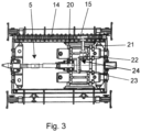
- Fig.3 shows an alternative embodiment of an arrangement of an earth drilling device 1 with the earth drilling device 1 and a drill string 5 in plan view.
- the same elements are provided with the same reference numerals and essentially the toothed belt drive of the transfer device 24 was Fig.1 replaced by a bevel gear drive.
- the counter element 14 is designed as a roller chain and, during the linear movement of the carriage 4, sets the rolling element 15, which is designed as a sprocket, in rotation.
- the rolling element 15, designed as a sprocket, is connected via a shaft 21 in a rotationally fixed manner to a bevel gear 22, designed as a pinion, of a transfer device 24 designed as a bevel gear and drives the bevel gear 23 of the transfer device 24, which in turn is rotationally fixedly connected to the holder 20 for the drill string 5, and thus the drill string 5 with the drill head 6.
- An interruption of the rotational movement takes place in an analogous manner to that already described for the embodiment in the Fig. 1 and 2 described, by means of a clutch on the transfer device 24 or alternatively by spatial separation of the rolling element 15 and counter element 14.
Landscapes
- Engineering & Computer Science (AREA)
- Life Sciences & Earth Sciences (AREA)
- Geology (AREA)
- Mining & Mineral Resources (AREA)
- Physics & Mathematics (AREA)
- Environmental & Geological Engineering (AREA)
- Fluid Mechanics (AREA)
- General Life Sciences & Earth Sciences (AREA)
- Geochemistry & Mineralogy (AREA)
- Mechanical Engineering (AREA)
- Earth Drilling (AREA)
Claims (12)
- Agencement d'un dispositif de forage du sol (1) pour l'introduction par poussée ou par traction d'un train de tiges de forage (5) dans le sol, l'agencement présentant un cadre (8) et un chariot (4) pouvant être déplacé en va-et-vient par rapport au cadre (8) avec un mouvement de translation, caractérisé en ce qu'au moins un élément de déroulement (15) est prévu, lequel est conçu pour se dérouler lors du mouvement de translation du chariot (4), le mouvement de rotation de l'élément de déroulement (15) étant transformé en un mouvement de rotation du train de tiges de forage (5).
- Agencement selon la revendication 1, dans lequel il est prévu un contre-élément (14) qui est en contact avec l'élément de déroulement (15) et sur lequel l'élément de déroulement (15) se déroule.
- Agencement selon la revendication 2, dans lequel l'élément de déroulement (15) est monté sur le chariot (4) et le contre-élément (14) est disposé de manière fixe à l'extérieur du chariot (4).
- Agencement selon la revendication 2 ou 3, dans lequel l'élément de déroulement (15) est une roue et/ou le contre-élément (14) est un élément d'entraînement linéaire.
- Agencement selon l'une des revendications 1 à 4, dans lequel l'élément de déroulement (15) présente un axe de rotation transversal au mouvement de translation du chariot (4).
- Agencement selon l'une des revendications 1 à 5, dans lequel l'élément de déroulement (15) est disposé de manière àa) être déplacé en translation transversalement à l'axe de rotation lors du déroulement oub) être déplacé longitudinalement à l'axe de rotation lors du déroulement.
- Agencement selon l'une des revendications 1 à 6, dans lequel il est prévu un dispositif de conversion (24) qui est relié à l'élément de déroulement (15) et qui est configuré pour convertir le mouvement de rotation de l'élément de déroulement (15) en un mouvement de rotation du train de tiges de forage (5).
- Agencement selon la revendication 7, dans lequel le dispositif de conversion (24) comporte un élément d'entraînement qui est en prise au moins indirecte avec l'élément de déroulement (15), et un élément de sortie qui est en prise au moins indirecte avec le train de tiges de forage (5).
- Agencement selon la revendication 8, dans lequel l'élément de sortie est une poulie dentée (16, 19) ou une roue conique (22, 23) et/ou l'élément d'entraînement est une poulie dentée (16, 19) ou une roue conique (22, 23).
- Dispositif de forage du sol (1) comprenant un agencement selon l'une des revendications 1 à 9.
- Procédé de fonctionnement d'un dispositif de forage du sol (1), dans lequel un chariot (4) du dispositif de forage du sol (1) est déplacé en va-et-vient par rapport à un cadre (8) avec un mouvement de translation pour enfoncer un train de tiges de forage (5) dans le sol dans une direction de travail de poussée ou de traction, caractérisé en ce qu'un élément de déroulement (15) se déroule lors du mouvement de translation et le mouvement de rotation de l'élément de déroulement (15) est transformé en un mouvement de rotation du train de tiges de forage (5).
- Utilisation d'un agencement d'un dispositif de forage du sol (1) pour l'introduction par poussée ou par traction d'un train de tiges de forage (5) dans le sol, l'agencement présentant un cadre (8) et un chariot (4) pouvant être déplacé en va-et-vient par rapport au cadre (8) avec un mouvement de translation, caractérisée en ce qu'au moins un élément de déroulement (15) est utilisé, lequel se déroule lors du mouvement de translation et le mouvement de déroulement est utilisé pour imprimer un mouvement de rotation au train de tiges de forage (5) au moyen du mouvement de rotation de l'élément de déroulement (15).
Applications Claiming Priority (1)
| Application Number | Priority Date | Filing Date | Title |
|---|---|---|---|
| DE102021000497.3A DE102021000497A1 (de) | 2021-02-02 | 2021-02-02 | Anordnung einer Erdbohrvorrichtung, Verfahren zum Betrieb einer Erdbohrvorrichtung und Verwendung einer Anordnung einer Erdbohrvorrichtung |
Publications (3)
| Publication Number | Publication Date |
|---|---|
| EP4036367A1 EP4036367A1 (fr) | 2022-08-03 |
| EP4036367C0 EP4036367C0 (fr) | 2024-05-01 |
| EP4036367B1 true EP4036367B1 (fr) | 2024-05-01 |
Family
ID=80119493
Family Applications (1)
| Application Number | Title | Priority Date | Filing Date |
|---|---|---|---|
| EP22154667.4A Active EP4036367B1 (fr) | 2021-02-02 | 2022-02-02 | Agencement d'un dispositif de forage du sol, procédé de fonctionnement d'un dispositif de forage du sol et utilisation d'un agencement d'un dispositif de forage du sol |
Country Status (4)
| Country | Link |
|---|---|
| US (1) | US11834921B2 (fr) |
| EP (1) | EP4036367B1 (fr) |
| AU (1) | AU2022200150A1 (fr) |
| DE (1) | DE102021000497A1 (fr) |
Family Cites Families (7)
| Publication number | Priority date | Publication date | Assignee | Title |
|---|---|---|---|---|
| US853010A (en) * | 1906-10-27 | 1907-05-07 | Davie Allen Gray | Post-hole digger. |
| US885041A (en) * | 1907-08-24 | 1908-04-21 | Robert Guthrie | Machine for boring post-holes. |
| US2643858A (en) | 1948-06-14 | 1953-06-30 | Utah Scient Res Foundation | Soil sampling machine |
| US2693345A (en) | 1950-01-10 | 1954-11-02 | James A Martin | Earth-boring apparatus |
| JP2624945B2 (ja) | 1994-11-29 | 1997-06-25 | 株式会社ホウショウ | 地中配管装置のリード管構造 |
| DE19608980C2 (de) | 1996-03-08 | 1998-05-07 | Tracto Technik | Vorrichtung zum Bohren im Erdreich |
| US7798252B2 (en) | 2007-03-07 | 2010-09-21 | Barbera James S | Method and apparatus for providing a continuous stroke auger boring machine |
-
2021
- 2021-02-02 DE DE102021000497.3A patent/DE102021000497A1/de active Pending
-
2022
- 2022-01-12 AU AU2022200150A patent/AU2022200150A1/en active Pending
- 2022-01-24 US US17/582,517 patent/US11834921B2/en active Active
- 2022-02-02 EP EP22154667.4A patent/EP4036367B1/fr active Active
Also Published As
| Publication number | Publication date |
|---|---|
| US20220243533A1 (en) | 2022-08-04 |
| US11834921B2 (en) | 2023-12-05 |
| EP4036367C0 (fr) | 2024-05-01 |
| DE102021000497A1 (de) | 2022-08-04 |
| AU2022200150A1 (en) | 2022-08-18 |
| EP4036367A1 (fr) | 2022-08-03 |
Similar Documents
| Publication | Publication Date | Title |
|---|---|---|
| DE102009035277B4 (de) | Bohrvorrichtung | |
| DE4113422C2 (fr) | ||
| DE2047587A1 (de) | Entkupplungsvorrichtung | |
| EP2048321B1 (fr) | Appareil de forage et procédé de fonctionnement d'un appareil de forage | |
| DE20301946U1 (de) | Teleskopierbares Bohrgestänge | |
| EP1580398B1 (fr) | Appareil et méthode pour constructions souterraines | |
| DE1477357B2 (de) | Vorrichtung zum spannen und loesen von in der spindel eines bohr und fraeswerks aufgenommenen werkzeugen | |
| DE102006062322B3 (de) | Horizontalpressbohranlage | |
| DE2810273C2 (de) | Vorrichtung zur Regelung der Vorschubgeschwindigkeit des Dorns in einem kontinuierlichen, mit gehaltenem Dorn arbeitenden Walzwerk | |
| EP0825326B1 (fr) | Procédé et dispositif pour le forage horizontal et pour la manipulation de tiges de forage | |
| EP4036367B1 (fr) | Agencement d'un dispositif de forage du sol, procédé de fonctionnement d'un dispositif de forage du sol et utilisation d'un agencement d'un dispositif de forage du sol | |
| EP3702576B1 (fr) | Dispositif de forage du sol et utilisation d'un dispositif de forage du sol | |
| DE19849963C2 (de) | Kompaktbohranlage zum Erstellen von Erdbohrungen | |
| EP3456914B1 (fr) | Dispositif de forage double tête et procédé de réalisation d'un forage | |
| DE3125013A1 (de) | Tiefbohrvorrichtung | |
| DE102014018100B3 (de) | "Antrieb einer Erdbohrvorrichtung, Erdbohrvorrichtung und Verfahren zum Antreiben einer Erdbohrvorrichtung" | |
| DE10338938B4 (de) | Vorschubvorrichtung für Walzgut und Verfahren zum Vorschieben eines Walzguts | |
| EP0169393A1 (fr) | Dispositif pour la production de forages d'une section transversale inaccessible | |
| EP2626506B1 (fr) | Dispositif de déplacement d'un moyen de travail dans la terre | |
| DE102019135680B3 (de) | Drehantrieb zum Verschwenken von zwei gelenkig miteinander verbundenen Mastarmen | |
| DE2817017C2 (de) | Horizontalpreßbohrgerät | |
| DE20001092U1 (de) | Spannbackenvorrichtung | |
| DE3501536C2 (de) | Vorrichtung zum unterirdischen Vorpressen von Rohrleitungsstrecken | |
| DE10218407B4 (de) | Vorrichtung zum Lösen von Gestängegewindeverbindungen | |
| EP4357532A1 (fr) | Système de vissage pour introduire une tige filetée dans un sol |
Legal Events
| Date | Code | Title | Description |
|---|---|---|---|
| PUAI | Public reference made under article 153(3) epc to a published international application that has entered the european phase |
Free format text: ORIGINAL CODE: 0009012 |
|
| STAA | Information on the status of an ep patent application or granted ep patent |
Free format text: STATUS: THE APPLICATION HAS BEEN PUBLISHED |
|
| AK | Designated contracting states |
Kind code of ref document: A1 Designated state(s): AL AT BE BG CH CY CZ DE DK EE ES FI FR GB GR HR HU IE IS IT LI LT LU LV MC MK MT NL NO PL PT RO RS SE SI SK SM TR |
|
| STAA | Information on the status of an ep patent application or granted ep patent |
Free format text: STATUS: REQUEST FOR EXAMINATION WAS MADE |
|
| 17P | Request for examination filed |
Effective date: 20230201 |
|
| RBV | Designated contracting states (corrected) |
Designated state(s): AL AT BE BG CH CY CZ DE DK EE ES FI FR GB GR HR HU IE IS IT LI LT LU LV MC MK MT NL NO PL PT RO RS SE SI SK SM TR |
|
| GRAP | Despatch of communication of intention to grant a patent |
Free format text: ORIGINAL CODE: EPIDOSNIGR1 |
|
| STAA | Information on the status of an ep patent application or granted ep patent |
Free format text: STATUS: GRANT OF PATENT IS INTENDED |
|
| INTG | Intention to grant announced |
Effective date: 20230907 |
|
| GRAJ | Information related to disapproval of communication of intention to grant by the applicant or resumption of examination proceedings by the epo deleted |
Free format text: ORIGINAL CODE: EPIDOSDIGR1 |
|
| STAA | Information on the status of an ep patent application or granted ep patent |
Free format text: STATUS: REQUEST FOR EXAMINATION WAS MADE |
|
| GRAP | Despatch of communication of intention to grant a patent |
Free format text: ORIGINAL CODE: EPIDOSNIGR1 |
|
| STAA | Information on the status of an ep patent application or granted ep patent |
Free format text: STATUS: GRANT OF PATENT IS INTENDED |
|
| INTC | Intention to grant announced (deleted) | ||
| INTG | Intention to grant announced |
Effective date: 20231124 |
|
| GRAS | Grant fee paid |
Free format text: ORIGINAL CODE: EPIDOSNIGR3 |
|
| GRAA | (expected) grant |
Free format text: ORIGINAL CODE: 0009210 |
|
| STAA | Information on the status of an ep patent application or granted ep patent |
Free format text: STATUS: THE PATENT HAS BEEN GRANTED |
|
| AK | Designated contracting states |
Kind code of ref document: B1 Designated state(s): AL AT BE BG CH CY CZ DE DK EE ES FI FR GB GR HR HU IE IS IT LI LT LU LV MC MK MT NL NO PL PT RO RS SE SI SK SM TR |
|
| REG | Reference to a national code |
Ref country code: GB Ref legal event code: FG4D Free format text: NOT ENGLISH |
|
| REG | Reference to a national code |
Ref country code: CH Ref legal event code: EP |
|
| REG | Reference to a national code |
Ref country code: DE Ref legal event code: R096 Ref document number: 502022000809 Country of ref document: DE |
|
| REG | Reference to a national code |
Ref country code: IE Ref legal event code: FG4D Free format text: LANGUAGE OF EP DOCUMENT: GERMAN |
|
| U01 | Request for unitary effect filed |
Effective date: 20240517 |
|
| U07 | Unitary effect registered |
Designated state(s): AT BE BG DE DK EE FI FR IT LT LU LV MT NL PT SE SI Effective date: 20240529 |