EP4036343B1 - Mantel für vorspannkabel und entsprechendes vorspannkabel - Google Patents
Mantel für vorspannkabel und entsprechendes vorspannkabel Download PDFInfo
- Publication number
- EP4036343B1 EP4036343B1 EP22154690.6A EP22154690A EP4036343B1 EP 4036343 B1 EP4036343 B1 EP 4036343B1 EP 22154690 A EP22154690 A EP 22154690A EP 4036343 B1 EP4036343 B1 EP 4036343B1
- Authority
- EP
- European Patent Office
- Prior art keywords
- sheath
- vent
- perforated wall
- filtering element
- cable
- Prior art date
- Legal status (The legal status is an assumption and is not a legal conclusion. Google has not performed a legal analysis and makes no representation as to the accuracy of the status listed.)
- Active
Links
Images

Classifications
-
- E—FIXED CONSTRUCTIONS
- E04—BUILDING
- E04C—STRUCTURAL ELEMENTS; BUILDING MATERIALS
- E04C5/00—Reinforcing elements, e.g. for concrete; Auxiliary elements therefor
- E04C5/08—Members specially adapted to be used in prestressed constructions
- E04C5/10—Ducts
Definitions
- the present invention relates to the field of prestressing cables for construction works.
- Prestressing cables in construction works frequently have a sinuous path with high and low points, the transverse force exerted by the cable being directed downwards in the vicinity of the high points and vice versa.
- vents When injecting the sheaths of these cables with the filling material, the air present in the sheath can be evacuated at the high points using devices called vents. These vents generally consist of a plastic shell fixed in a sealed manner to the sheath and a tube, forming part of or fixed to this shell, which allows the air and the filling material to be channelled out of the sheath and the material constituting the structure (most often concrete).
- the technique is called external prestressing of the concrete.
- the segments that cross the structure in the blocks or spacers make it possible to take up the forces exerted by the cable and transmit them to the structure.
- the high and low points of the cable are then located in deflecting devices such as saddles or curved tubes.
- the cable sheaths pass through these deflector devices by passing through metal formwork tubes, curved and embedded in the concrete.
- the cable can then be dismantled for replacement, by cutting it in accessible areas and releasing it from the deflector devices and anchors.
- EP 0 875 636 A1 proposes a vent to reduce the incidence of these difficulties by using a channel integrated into the sheath and extending along it to evacuate air outside the segment of sheath passing through the formwork tube. The operator must wait until the grout reaches the vent to purge the air and a small volume of grout in order to validate that the sheath is properly filled. However, each purge requires the intervention of an operator and it may remain uncertain whether an effective and complete purge of air from the sheath can be carried out with this process.
- the document EP 0 875 636 A1 discloses a sheath for a prestressing cable according to the preamble of claim 1.
- An aim of the present invention is to improve the efficiency of the evacuation of air from the sheath at the high points of a prestressing cable, in particular an external one.
- a sheath for a prestressing cable comprising a tubular sheath body having an internal volume (18) suitable for receiving reinforcements (16) of the prestressing cable and a filling product and at least one vent between the internal volume of the sheath and the exterior of the sheath, characterized in that the vent comprises a filter element permeable to air and impermeable to the filling product.
- the filter element Since the filter element is air permeable in the sheath, air is evacuated to the outside of the sheath when the filler is injected into the sheath.
- the filler gradually fills the space vacated by the exhaust air until the filter element and the filler come into contact. Since the filter element is impermeable to the filler, the vent is blocked when the filler comes into contact with the filter element.
- the vent includes a first perforated wall secured to the tubular sheath body, the filter element being positioned against an inner face of the first perforated wall.
- the vent includes a second perforated wall, the filter element being positioned between the first and second perforated walls.
- the vent comprises a vent body attached to the tubular sheath body, wherein the first perforated wall is part of the vent body, and wherein the vent body comprises a housing receiving the second perforated wall.
- the second perforated wall is secured to the vent body so as to secure the filter element between the first and second perforated walls.
- vent body is engaged in an opening provided on the tubular sheath body.
- the filter element has a porosity of between 0.5 ⁇ m and 200 ⁇ m.
- the filter element has a porosity of between 1 ⁇ m and 100 ⁇ m.
- the at least one vent is placed at a high point of the sheath layout.
- the high point of the sheath path is in a deflector tube having a bend, the vent being located on the outside of the bend of the deflector tube.
- outside of the bend is meant the high position of the bend.
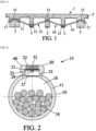
- FIG. 1 shows an example of a construction work 1 of which an upper part 2 is supported on transverse elements 3.
- the construction work 1 is for example constructed of concrete, prefabricated or cast in situ.
- the construction work 1 comprises one or more prestressing cables 15.
- the prestressing cable 15 comprises a prestressing sheath 10 formed mainly by a tubular sheath body 11.
- the tubular sheath body 11 is formed by a succession of tubes welded end to end or connected using heat-welded sleeves. It can also be formed by a single continuous tube.
- the sheath 10 has a substantially circular section, but any other shape is possible.
- the tubular sheath body 11 is made of plastic material, for example high-density polyethylene (HDPE).
- the example of the work of the figure 1 is reinforced by an external prestressing cable whose sheath 10 has a sinuous path comprising high points 12 and low points 13.
- the sinuous path further comprises rectilinear segments 14 between the high points 12 and the low points 13.
- the high points 12 and the low points 13 are located at the level of the transverse elements 3, and the rectilinear segments 14 run outside the concrete of the structure 1.
- the sheath 10 is completely embedded in the material of the structure 1, and it is a so-called internal prestress which is applied to the structure 1.
- the cable 15 comprises a set of reinforcements 16 housed in the sheath 10.
- the reinforcements 16 are anchored at their ends by means of conventional anchoring devices 17 visible in the figure 1
- the reinforcements 16 are tensioned so as to exert prestressing forces on at least part of the structure 1.
- the internal volume 18 of the sheath 10 not occupied by the reinforcements 16 is filled with a filling product, not shown.
- the filling product is a cement product, such as a cement grout having thixotropic properties adapted to this type of cable (essentially horizontal layout).
- the filling product makes it possible to fill the volume 18 so as to protect the reinforcements 16 against corrosion. It can also contribute to providing adhesion between the reinforcements 16 and the structure 1.
- a complete filling of volume 18 is desirable for the filler to fully play its role.
- the injection of the filler can take place by one end of the sheath 10 or both, and/or at one or more places on its path, for example near low points 13 of the winding path.
- the sheath 10 further comprises at least one vent 20.
- the number of vents 20 may depend on the length and geometry of the sheath 10. For example, a vent 20 is placed at each high point 12.
- the vents 20 are preferably arranged on the outer side of the curvature of the sheath 10.
- the vent 20 comprises a filter element 21.
- the porosity of the element 21 is typically between 0.5 ⁇ m and 200 ⁇ m. Preferably, the porosity of the element 21 is between 1 ⁇ m and 100 ⁇ m.
- the filter element 21 is for example a geotextile membrane comprising a set of fibers. The membrane is for example a glass fiber membrane with a porosity of 1 ⁇ m marketed by PALL (registered trademark).
- the filter element 21 may be a volume of a powdery material in the form of grains or granules contained in a fluid-permeable envelope, such as a mesh fabric fine enough to retain the grains.
- the powdery material may be sand or be in the form of high-density polyethylene (HDPE) granules, for example.
- HDPE high-density polyethylene
- the filter element 21 is permeable to air from the inside of the sheath 10 and sealed to the filling product from the inside of the sheath 10.
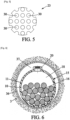
- the vent 20 comprises two perforated walls 22, 23 between which the filter element 21 is placed.
- the first perforated wall 22 belongs to a vent body 40 fixed to the duct body 11.
- FIG 4 shows the perforations 28 between the external face 24 and the internal face 25 of the perforated wall 22.
- the perforations 28 have, for example, a circular section or, as illustrated in the figure 3 , an oblong section. Any other shape of the section of the perforations 28 is of course possible.
- An orifice 32 can open onto the internal face 25 of the first perforated wall 22 in order to receive a screw 29 for assembling the second perforated wall 23.
- a screw 29 for assembling the second perforated wall 23.
- only one 32 hole is provided.
- the vent body 40 has, for example, a substantially cylindrical external shape comprising a narrowed region 33 which engages in an opening provided in the sheath body 11.
- the vent body 40 has a cavity delimited by the internal face 25 of the perforated wall 22 and a generally cylindrical lateral surface 31.
- This cavity forms a housing 27 having a receiving zone 34 and a filtration zone 35 of substantially cylindrical shapes.
- the filtration zone 35 is adjacent to the perforated wall 22.
- the diameter of the receiving zone 34 corresponds to that of the filter element 21 and is slightly smaller than that of the filtration zone 35.
- the vent body 40 may be made of the same material as the sheath body 11, but this is not obligatory.
- vent body 40 and the sheath body 11 can optionally be welded together, or screwed if a force engagement is not sufficient.
- the filter element 21 is placed against the internal face 25 of the first perforated wall 22.
- the filter element 21 can be installed in the housing 27 of the vent body 40. It can be introduced into the vent body 40 via the receiving zone 34 and be housed in the filtration zone 35.
- the perforated wall 23 is in the form of a disc with a section close to that of the receiving zone 34 of the vent body 40, in order to be able to penetrate into this zone 34 and hold the filter element 21 against the first perforated wall 24.
- the wall 23 has perforations which are for example circular in shape, but any other shape is conceivable.
- the radius of the holes 30 may be between 0.5 mm and 2 mm, preferably between 1 mm and 1.5 mm.
- the thickness of the perforated wall 23 is for example 0.5 mm to 2 mm. It may be made of a metallic material, for example stainless steel, or plastic.
- a screw 29 holds the perforated wall 23 in position relative to the vent body 40, passing through one of the holes 30 to achieve fixing in the orifice 32 of the vent body 40.
- Other mechanisms for fixing the perforated wall 23 to the vent body 40 are conceivable, for example by embedding in the housing 27, with pins, circlips or the like.
- the filter element 21 can thus be immobilized between the perforated walls 22, 23 before fixing the vent body 40 and the sheath body 11.
- the vent 20 is arranged between the inside of the sheath 10 and the outside of the sheath 10.
- the communication permitted by the vent 20 is selective thanks to the filter element 21 permeable to air and impermeable to the filling product.
- the filter element 21 lets the air out while retaining the filling product inside the sheath 10.
- the formation is prevented or limited air pockets, particularly at the high points where the vent 20 is installed. Complete filling of the sheath 10 with the filling product is thus promoted.
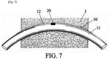
- the sheath 10 passes through a deflector tube 36, or casing tube, as illustrated in the figures 6 And 7 .
- a deflector tube 36 or casing tube, as illustrated in the figures 6 And 7 .
- the deflector tube 36 has a curvature, the vent 20 being able to be placed on the outside of the curvature.
- the internal diameter of the deflector tube 36 is for example between 10% and 25% greater than a diameter of the sheath 10.
- a limited space 37 therefore exists between the deflector tube 36 and the sheath body 11.
- vent 20 makes it possible to reduce its size, no valve being required to stop the evacuation of the air present in the duct 10.
- the reduction in size allows the installation of the vent 20 in a reduced space.
- the vent 20 can thus be installed on the duct body 11 in the space 37.
- vents 20 no operator needs to be stationed next to the vents 20 to operate valves or other components, or to control the vents during injection. This allows the installation of the vent 20 in areas that are difficult to access, such as space 37 of the figure 6 .
- the configuration of the vent 20, and in particular the configuration of the element 21, makes it possible to inject the filling product at atmospheric pressure or under pressure (of the order of 5 bar) without creating a vacuum.
- atmospheric pressure or under pressure of the order of 5 bar
Landscapes
- Engineering & Computer Science (AREA)
- Architecture (AREA)
- Civil Engineering (AREA)
- Structural Engineering (AREA)
- Reinforcement Elements For Buildings (AREA)
- Cable Accessories (AREA)
- Insulated Conductors (AREA)
- Laying Of Electric Cables Or Lines Outside (AREA)
Claims (11)
- Hülle für ein Vorspannkabel, umfassend einen rohrförmigen Hüllenkörper (11) mit einem Innenvolumen (18), das dazu geeignet ist, Litzen (16) des Vorspannkabels und ein Füllprodukt aufzunehmen, sowie wenigstens eine Entlüftung (20) zwischen dem Innenvolumen der Hülle und dem Äußeren der Hülle, dadurch gekennzeichnet, dass die Entlüftung ein Filterelement (21) umfasst, das luftdurchlässig und für das Füllprodukt dicht ist.
- Hülle nach Anspruch 1, wobei die Entlüftung eine erste perforierte Wand (22) umfasst, die an dem rohrförmigen Hüllenkörper (11) befestigt ist, wobei das Filterelement (21) an einer Innenseite (25) der ersten perforierten Wand platziert ist.
- Hülle nach Anspruch 2, wobei die Entlüftung (20) eine zweite perforierte Wand (23) umfasst, wobei das Filterelement (21) zwischen der ersten und der zweiten perforierten Wand (22, 23) platziert ist.
- Hülle nach Anspruch 3, wobei die Entlüftung (20) einen Entlüftungskörper (40) umfasst, der an dem rohrförmigen Hüllenkörper (11) befestigt ist, wobei die erste perforierte Wand (22) zu dem Entlüftungskörper gehört, und wobei der Entlüftungskörper (40) eine Aufnahme (27) umfasst, die die zweite perforierte Wand (23) aufnimmt.
- Hülle nach Anspruch 4, wobei die zweite perforierte Wand (23) an dem Entlüftungskörper (40) befestigt ist, um das Filterelement (21) zwischen der ersten und der zweiten perforierten Wand (22, 23) zu fixieren.
- Hülle nach Anspruch 4 oder 5, wobei der Entlüftungskörper (40) in eine Öffnung am rohrförmigen Hüllenkörper (11) eingreift.
- Hülle nach einem der vorhergehenden Ansprüche, wobei das Filterelement (21) eine Porosität zwischen 0,5 µm und 200 µm aufweist.
- Hülle nach einem der vorhergehenden Ansprüche, wobei das Filterelement (21) eine Porosität zwischen 1 µm und 100 µm aufweist.
- Vorspannkabel für ein Bauwerk, wobei das Vorspannkabel (15) umfasst:- eine Hülle (10) nach einem der vorhergehenden Ansprüche, die entlang eines Verlaufs innerhalb des Bauwerks (1) angeordnet ist;- Litzen (16), die in der Hülle aufgenommen und derart gespannt sind, dass sie Kräfte auf wenigstens einen Teil des Bauwerks ausüben;- ein Füllmaterial, das in die Hülle injiziert wird, um das von den Litzen nicht eingenommene Volumen auszufüllen.
- Vorspannkabel nach Anspruch 9, wobei die wenigstens eine Entlüftung (20) an einem Hochpunkt (12) des Verlaufs der Hülle (10) angeordnet ist.
- Vorspannkabel nach Anspruch 10, wobei der Hochpunkt (12) des Verlaufs der Hülle (10) in einem Umlenkrohr (36) liegt, das eine Krümmung aufweist, wobei die Entlüftung (20) auf der Außenseite der Krümmung des Umlenkrohrs angeordnet ist.
Applications Claiming Priority (1)
| Application Number | Priority Date | Filing Date | Title |
|---|---|---|---|
| FR2101004A FR3119406B1 (fr) | 2021-02-02 | 2021-02-02 | Gaine pour cable de precontrainte et cable de precontrainte associe |
Publications (2)
| Publication Number | Publication Date |
|---|---|
| EP4036343A1 EP4036343A1 (de) | 2022-08-03 |
| EP4036343B1 true EP4036343B1 (de) | 2024-09-18 |
Family
ID=74860274
Family Applications (1)
| Application Number | Title | Priority Date | Filing Date |
|---|---|---|---|
| EP22154690.6A Active EP4036343B1 (de) | 2021-02-02 | 2022-02-02 | Mantel für vorspannkabel und entsprechendes vorspannkabel |
Country Status (4)
| Country | Link |
|---|---|
| EP (1) | EP4036343B1 (de) |
| FI (1) | FI4036343T3 (de) |
| FR (1) | FR3119406B1 (de) |
| HU (1) | HUE069027T2 (de) |
Family Cites Families (3)
| Publication number | Priority date | Publication date | Assignee | Title |
|---|---|---|---|---|
| US5158395A (en) * | 1985-01-17 | 1992-10-27 | Holmberg Dick L | Erosion control foundation mat and method |
| FR2762864B1 (fr) | 1997-05-02 | 1999-07-23 | Freyssinet Int Stup | Element de gaine pour cable de precontrainte |
| WO2008007133A1 (en) * | 2006-07-14 | 2008-01-17 | Andrew Mountain | Conduit device and filter vent for concrete formwork |
-
2021
- 2021-02-02 FR FR2101004A patent/FR3119406B1/fr active Active
-
2022
- 2022-02-02 FI FIEP22154690.6T patent/FI4036343T3/fi active
- 2022-02-02 HU HUE22154690A patent/HUE069027T2/hu unknown
- 2022-02-02 EP EP22154690.6A patent/EP4036343B1/de active Active
Also Published As
| Publication number | Publication date |
|---|---|
| HUE069027T2 (hu) | 2025-02-28 |
| FI4036343T3 (fi) | 2024-11-19 |
| FR3119406A1 (fr) | 2022-08-05 |
| EP4036343A1 (de) | 2022-08-03 |
| FR3119406B1 (fr) | 2023-10-13 |
Similar Documents
| Publication | Publication Date | Title |
|---|---|---|
| EP1559847B1 (de) | Spannelement zur Herstellung einer Verankerung | |
| EP2964837B1 (de) | Verfahren zur herstellung einer schlitzwand und nach diesem verfahren hergestellte schlitzwand | |
| EP0122860B1 (de) | Verfahren und Vorrichtungen zum Einfetten von Spanngliedenden | |
| FR2593202A1 (fr) | Procede pour fabriquer un pieu en beton precontraint coule sur place | |
| FR2491529A1 (fr) | Dispositif pour former un evidement dans des elements prefabriques en beton | |
| EP3658711A1 (de) | Verbesserte anordnung mit einem strukturkabel und einem sattel | |
| EP3580403A1 (de) | Ankervorrichtung für vorgespannte gusswand | |
| CA3071589A1 (fr) | Dispositif d'ancrage d'armatures | |
| FR2492870A1 (fr) | Tete d'ancrage de cable pour ouvrage en beton precontraint | |
| EP4036343A1 (de) | Mantel für vorspannkabel und entsprechendes vorspannkabel | |
| FR2858343A1 (fr) | Entrevous emboitable moule | |
| EP0875636B1 (de) | Vorspannkabel und Spannkanal dafür | |
| FR2539792A1 (fr) | Procede de construction de structures etanches, telles que des reservoirs | |
| OA10392A (en) | Conduite de circulation de fluide | |
| FR2723116A1 (fr) | Conduit souterrain | |
| EP2594700B1 (de) | Kabel für Bauwerke und Verankerungsverfahren für solches Kabel | |
| EP1476603B1 (de) | Ankerhülse zur verbindung eines funktionnellen gliedes mit einem substrat | |
| FR2742796A1 (fr) | Procede de realisation d'un anneau de voussoirs, anneau de voussoirs obtenu, cache pour la mise en oeuvre du procede et voussoir destine a cooperer avec un tel cache | |
| FR2694957A1 (fr) | Dispositif de coffrage pour la constitution d'un mur en béton banché. | |
| EP3945157B1 (de) | Selbstblockierendes bodenbelagelement | |
| FR2962066A1 (fr) | Procede de fabrication d'un element structurel en beton et element structurel prefabrique en beton. | |
| FR2581678A1 (fr) | Procede pour la realisation d'une structure en beton arme noyee dans le sol | |
| FR2722819A1 (fr) | Poche et procede de calage ou de mise en pression de deux elements de construction | |
| EP2963180B1 (de) | Dichtungsanordnung zwischen gleisschwelle und schwellenschuh | |
| FR2485586A1 (fr) | Procede pour rendre etanches a l'eau des joints entre elements de construction |
Legal Events
| Date | Code | Title | Description |
|---|---|---|---|
| PUAI | Public reference made under article 153(3) epc to a published international application that has entered the european phase |
Free format text: ORIGINAL CODE: 0009012 |
|
| STAA | Information on the status of an ep patent application or granted ep patent |
Free format text: STATUS: THE APPLICATION HAS BEEN PUBLISHED |
|
| AK | Designated contracting states |
Kind code of ref document: A1 Designated state(s): AL AT BE BG CH CY CZ DE DK EE ES FI FR GB GR HR HU IE IS IT LI LT LU LV MC MK MT NL NO PL PT RO RS SE SI SK SM TR |
|
| STAA | Information on the status of an ep patent application or granted ep patent |
Free format text: STATUS: REQUEST FOR EXAMINATION WAS MADE |
|
| 17P | Request for examination filed |
Effective date: 20230123 |
|
| RBV | Designated contracting states (corrected) |
Designated state(s): AL AT BE BG CH CY CZ DE DK EE ES FI FR GB GR HR HU IE IS IT LI LT LU LV MC MK MT NL NO PL PT RO RS SE SI SK SM TR |
|
| P01 | Opt-out of the competence of the unified patent court (upc) registered |
Effective date: 20230526 |
|
| GRAP | Despatch of communication of intention to grant a patent |
Free format text: ORIGINAL CODE: EPIDOSNIGR1 |
|
| STAA | Information on the status of an ep patent application or granted ep patent |
Free format text: STATUS: GRANT OF PATENT IS INTENDED |
|
| INTG | Intention to grant announced |
Effective date: 20240419 |
|
| GRAS | Grant fee paid |
Free format text: ORIGINAL CODE: EPIDOSNIGR3 |
|
| GRAA | (expected) grant |
Free format text: ORIGINAL CODE: 0009210 |
|
| STAA | Information on the status of an ep patent application or granted ep patent |
Free format text: STATUS: THE PATENT HAS BEEN GRANTED |
|
| AK | Designated contracting states |
Kind code of ref document: B1 Designated state(s): AL AT BE BG CH CY CZ DE DK EE ES FI FR GB GR HR HU IE IS IT LI LT LU LV MC MK MT NL NO PL PT RO RS SE SI SK SM TR |
|
| REG | Reference to a national code |
Ref country code: GB Ref legal event code: FG4D Free format text: NOT ENGLISH |
|
| RIN1 | Information on inventor provided before grant (corrected) |
Inventor name: MURAT, MATTHIEU Inventor name: CARRY, ANTOINE |
|
| REG | Reference to a national code |
Ref country code: CH Ref legal event code: EP |
|
| REG | Reference to a national code |
Ref country code: DE Ref legal event code: R096 Ref document number: 602022006102 Country of ref document: DE |
|
| REG | Reference to a national code |
Ref country code: IE Ref legal event code: FG4D Free format text: LANGUAGE OF EP DOCUMENT: FRENCH |
|
| REG | Reference to a national code |
Ref country code: FI Ref legal event code: FGE |
|
| REG | Reference to a national code |
Ref country code: LT Ref legal event code: MG9D |
|
| PG25 | Lapsed in a contracting state [announced via postgrant information from national office to epo] |
Ref country code: NO Free format text: LAPSE BECAUSE OF FAILURE TO SUBMIT A TRANSLATION OF THE DESCRIPTION OR TO PAY THE FEE WITHIN THE PRESCRIBED TIME-LIMIT Effective date: 20241218 |
|
| PG25 | Lapsed in a contracting state [announced via postgrant information from national office to epo] |
Ref country code: GR Free format text: LAPSE BECAUSE OF FAILURE TO SUBMIT A TRANSLATION OF THE DESCRIPTION OR TO PAY THE FEE WITHIN THE PRESCRIBED TIME-LIMIT Effective date: 20241219 |
|
| PG25 | Lapsed in a contracting state [announced via postgrant information from national office to epo] |
Ref country code: BG Free format text: LAPSE BECAUSE OF FAILURE TO SUBMIT A TRANSLATION OF THE DESCRIPTION OR TO PAY THE FEE WITHIN THE PRESCRIBED TIME-LIMIT Effective date: 20240918 |
|
| PG25 | Lapsed in a contracting state [announced via postgrant information from national office to epo] |
Ref country code: LV Free format text: LAPSE BECAUSE OF FAILURE TO SUBMIT A TRANSLATION OF THE DESCRIPTION OR TO PAY THE FEE WITHIN THE PRESCRIBED TIME-LIMIT Effective date: 20240918 |
|
| PG25 | Lapsed in a contracting state [announced via postgrant information from national office to epo] |
Ref country code: HR Free format text: LAPSE BECAUSE OF FAILURE TO SUBMIT A TRANSLATION OF THE DESCRIPTION OR TO PAY THE FEE WITHIN THE PRESCRIBED TIME-LIMIT Effective date: 20240918 |
|
| REG | Reference to a national code |
Ref country code: NL Ref legal event code: MP Effective date: 20240918 |
|
| PG25 | Lapsed in a contracting state [announced via postgrant information from national office to epo] |
Ref country code: RS Free format text: LAPSE BECAUSE OF FAILURE TO SUBMIT A TRANSLATION OF THE DESCRIPTION OR TO PAY THE FEE WITHIN THE PRESCRIBED TIME-LIMIT Effective date: 20241218 |
|
| PG25 | Lapsed in a contracting state [announced via postgrant information from national office to epo] |
Ref country code: RS Free format text: LAPSE BECAUSE OF FAILURE TO SUBMIT A TRANSLATION OF THE DESCRIPTION OR TO PAY THE FEE WITHIN THE PRESCRIBED TIME-LIMIT Effective date: 20241218 Ref country code: NO Free format text: LAPSE BECAUSE OF FAILURE TO SUBMIT A TRANSLATION OF THE DESCRIPTION OR TO PAY THE FEE WITHIN THE PRESCRIBED TIME-LIMIT Effective date: 20241218 Ref country code: LV Free format text: LAPSE BECAUSE OF FAILURE TO SUBMIT A TRANSLATION OF THE DESCRIPTION OR TO PAY THE FEE WITHIN THE PRESCRIBED TIME-LIMIT Effective date: 20240918 Ref country code: HR Free format text: LAPSE BECAUSE OF FAILURE TO SUBMIT A TRANSLATION OF THE DESCRIPTION OR TO PAY THE FEE WITHIN THE PRESCRIBED TIME-LIMIT Effective date: 20240918 Ref country code: GR Free format text: LAPSE BECAUSE OF FAILURE TO SUBMIT A TRANSLATION OF THE DESCRIPTION OR TO PAY THE FEE WITHIN THE PRESCRIBED TIME-LIMIT Effective date: 20241219 Ref country code: BG Free format text: LAPSE BECAUSE OF FAILURE TO SUBMIT A TRANSLATION OF THE DESCRIPTION OR TO PAY THE FEE WITHIN THE PRESCRIBED TIME-LIMIT Effective date: 20240918 |
|
| REG | Reference to a national code |
Ref country code: AT Ref legal event code: MK05 Ref document number: 1724803 Country of ref document: AT Kind code of ref document: T Effective date: 20240918 |
|
| PG25 | Lapsed in a contracting state [announced via postgrant information from national office to epo] |
Ref country code: NL Free format text: LAPSE BECAUSE OF FAILURE TO SUBMIT A TRANSLATION OF THE DESCRIPTION OR TO PAY THE FEE WITHIN THE PRESCRIBED TIME-LIMIT Effective date: 20240918 |
|
| REG | Reference to a national code |
Ref country code: HU Ref legal event code: AG4A Ref document number: E069027 Country of ref document: HU |
|
| PG25 | Lapsed in a contracting state [announced via postgrant information from national office to epo] |
Ref country code: PT Free format text: LAPSE BECAUSE OF FAILURE TO SUBMIT A TRANSLATION OF THE DESCRIPTION OR TO PAY THE FEE WITHIN THE PRESCRIBED TIME-LIMIT Effective date: 20250120 Ref country code: IS Free format text: LAPSE BECAUSE OF FAILURE TO SUBMIT A TRANSLATION OF THE DESCRIPTION OR TO PAY THE FEE WITHIN THE PRESCRIBED TIME-LIMIT Effective date: 20250118 |
|
| PG25 | Lapsed in a contracting state [announced via postgrant information from national office to epo] |
Ref country code: SM Free format text: LAPSE BECAUSE OF FAILURE TO SUBMIT A TRANSLATION OF THE DESCRIPTION OR TO PAY THE FEE WITHIN THE PRESCRIBED TIME-LIMIT Effective date: 20240918 Ref country code: RO Free format text: LAPSE BECAUSE OF FAILURE TO SUBMIT A TRANSLATION OF THE DESCRIPTION OR TO PAY THE FEE WITHIN THE PRESCRIBED TIME-LIMIT Effective date: 20240918 |
|
| PG25 | Lapsed in a contracting state [announced via postgrant information from national office to epo] |
Ref country code: ES Free format text: LAPSE BECAUSE OF FAILURE TO SUBMIT A TRANSLATION OF THE DESCRIPTION OR TO PAY THE FEE WITHIN THE PRESCRIBED TIME-LIMIT Effective date: 20240918 |
|
| PG25 | Lapsed in a contracting state [announced via postgrant information from national office to epo] |
Ref country code: AT Free format text: LAPSE BECAUSE OF FAILURE TO SUBMIT A TRANSLATION OF THE DESCRIPTION OR TO PAY THE FEE WITHIN THE PRESCRIBED TIME-LIMIT Effective date: 20240918 Ref country code: EE Free format text: LAPSE BECAUSE OF FAILURE TO SUBMIT A TRANSLATION OF THE DESCRIPTION OR TO PAY THE FEE WITHIN THE PRESCRIBED TIME-LIMIT Effective date: 20240918 |
|
| PG25 | Lapsed in a contracting state [announced via postgrant information from national office to epo] |
Ref country code: CZ Free format text: LAPSE BECAUSE OF FAILURE TO SUBMIT A TRANSLATION OF THE DESCRIPTION OR TO PAY THE FEE WITHIN THE PRESCRIBED TIME-LIMIT Effective date: 20240918 Ref country code: PL Free format text: LAPSE BECAUSE OF FAILURE TO SUBMIT A TRANSLATION OF THE DESCRIPTION OR TO PAY THE FEE WITHIN THE PRESCRIBED TIME-LIMIT Effective date: 20240918 |
|
| PG25 | Lapsed in a contracting state [announced via postgrant information from national office to epo] |
Ref country code: SK Free format text: LAPSE BECAUSE OF FAILURE TO SUBMIT A TRANSLATION OF THE DESCRIPTION OR TO PAY THE FEE WITHIN THE PRESCRIBED TIME-LIMIT Effective date: 20240918 Ref country code: IT Free format text: LAPSE BECAUSE OF FAILURE TO SUBMIT A TRANSLATION OF THE DESCRIPTION OR TO PAY THE FEE WITHIN THE PRESCRIBED TIME-LIMIT Effective date: 20240918 |
|
| REG | Reference to a national code |
Ref country code: DE Ref legal event code: R097 Ref document number: 602022006102 Country of ref document: DE |
|
| PG25 | Lapsed in a contracting state [announced via postgrant information from national office to epo] |
Ref country code: DK Free format text: LAPSE BECAUSE OF FAILURE TO SUBMIT A TRANSLATION OF THE DESCRIPTION OR TO PAY THE FEE WITHIN THE PRESCRIBED TIME-LIMIT Effective date: 20240918 |
|
| PLBE | No opposition filed within time limit |
Free format text: ORIGINAL CODE: 0009261 |
|
| STAA | Information on the status of an ep patent application or granted ep patent |
Free format text: STATUS: NO OPPOSITION FILED WITHIN TIME LIMIT |
|
| 26N | No opposition filed |
Effective date: 20250619 |
|
| REG | Reference to a national code |
Ref country code: DE Ref legal event code: R119 Ref document number: 602022006102 Country of ref document: DE |
|
| PG25 | Lapsed in a contracting state [announced via postgrant information from national office to epo] |
Ref country code: SE Free format text: LAPSE BECAUSE OF FAILURE TO SUBMIT A TRANSLATION OF THE DESCRIPTION OR TO PAY THE FEE WITHIN THE PRESCRIBED TIME-LIMIT Effective date: 20240918 |
|
| PG25 | Lapsed in a contracting state [announced via postgrant information from national office to epo] |
Ref country code: MC Free format text: LAPSE BECAUSE OF FAILURE TO SUBMIT A TRANSLATION OF THE DESCRIPTION OR TO PAY THE FEE WITHIN THE PRESCRIBED TIME-LIMIT Effective date: 20240918 |
|
| PG25 | Lapsed in a contracting state [announced via postgrant information from national office to epo] |
Ref country code: LU Free format text: LAPSE BECAUSE OF NON-PAYMENT OF DUE FEES Effective date: 20250202 |
|
| REG | Reference to a national code |
Ref country code: BE Ref legal event code: MM Effective date: 20250228 |
|
| PG25 | Lapsed in a contracting state [announced via postgrant information from national office to epo] |
Ref country code: DE Free format text: LAPSE BECAUSE OF NON-PAYMENT OF DUE FEES Effective date: 20250902 |
|
| PG25 | Lapsed in a contracting state [announced via postgrant information from national office to epo] |
Ref country code: BE Free format text: LAPSE BECAUSE OF NON-PAYMENT OF DUE FEES Effective date: 20250228 |
|
| PG25 | Lapsed in a contracting state [announced via postgrant information from national office to epo] |
Ref country code: IE Free format text: LAPSE BECAUSE OF NON-PAYMENT OF DUE FEES Effective date: 20250202 |
|
| REG | Reference to a national code |
Ref country code: CH Ref legal event code: U11 Free format text: ST27 STATUS EVENT CODE: U-0-0-U10-U11 (AS PROVIDED BY THE NATIONAL OFFICE) Effective date: 20260301 |
|
| PGFP | Annual fee paid to national office [announced via postgrant information from national office to epo] |
Ref country code: HU Payment date: 20260223 Year of fee payment: 5 |
|
| PGFP | Annual fee paid to national office [announced via postgrant information from national office to epo] |
Ref country code: GB Payment date: 20260121 Year of fee payment: 5 |
|
| PGFP | Annual fee paid to national office [announced via postgrant information from national office to epo] |
Ref country code: FI Payment date: 20260121 Year of fee payment: 5 |
|
| PGFP | Annual fee paid to national office [announced via postgrant information from national office to epo] |
Ref country code: FR Payment date: 20260121 Year of fee payment: 5 |
|
| PGFP | Annual fee paid to national office [announced via postgrant information from national office to epo] |
Ref country code: CH Payment date: 20260301 Year of fee payment: 5 |