EP4035643A1 - Massagevorrichtung - Google Patents
Massagevorrichtung Download PDFInfo
- Publication number
- EP4035643A1 EP4035643A1 EP21173639.2A EP21173639A EP4035643A1 EP 4035643 A1 EP4035643 A1 EP 4035643A1 EP 21173639 A EP21173639 A EP 21173639A EP 4035643 A1 EP4035643 A1 EP 4035643A1
- Authority
- EP
- European Patent Office
- Prior art keywords
- massage
- base
- massage head
- enclosure
- cavity
- Prior art date
- Legal status (The legal status is an assumption and is not a legal conclusion. Google has not performed a legal analysis and makes no representation as to the accuracy of the status listed.)
- Granted
Links
Images
Classifications
-
- A—HUMAN NECESSITIES
- A61—MEDICAL OR VETERINARY SCIENCE; HYGIENE
- A61H—PHYSICAL THERAPY APPARATUS, e.g. DEVICES FOR LOCATING OR STIMULATING REFLEX POINTS IN THE BODY; ARTIFICIAL RESPIRATION; MASSAGE; BATHING DEVICES FOR SPECIAL THERAPEUTIC OR HYGIENIC PURPOSES OR SPECIFIC PARTS OF THE BODY
- A61H7/00—Devices for suction-kneading massage; Devices for massaging the skin by rubbing or brushing not otherwise provided for
- A61H7/002—Devices for suction-kneading massage; Devices for massaging the skin by rubbing or brushing not otherwise provided for by rubbing or brushing
- A61H7/004—Devices for suction-kneading massage; Devices for massaging the skin by rubbing or brushing not otherwise provided for by rubbing or brushing power-driven, e.g. electrical
-
- A—HUMAN NECESSITIES
- A61—MEDICAL OR VETERINARY SCIENCE; HYGIENE
- A61H—PHYSICAL THERAPY APPARATUS, e.g. DEVICES FOR LOCATING OR STIMULATING REFLEX POINTS IN THE BODY; ARTIFICIAL RESPIRATION; MASSAGE; BATHING DEVICES FOR SPECIAL THERAPEUTIC OR HYGIENIC PURPOSES OR SPECIFIC PARTS OF THE BODY
- A61H23/00—Percussion or vibration massage, e.g. using supersonic vibration; Suction-vibration massage; Massage with moving diaphragms
- A61H23/02—Percussion or vibration massage, e.g. using supersonic vibration; Suction-vibration massage; Massage with moving diaphragms with electric or magnetic drive
-
- A—HUMAN NECESSITIES
- A61—MEDICAL OR VETERINARY SCIENCE; HYGIENE
- A61H—PHYSICAL THERAPY APPARATUS, e.g. DEVICES FOR LOCATING OR STIMULATING REFLEX POINTS IN THE BODY; ARTIFICIAL RESPIRATION; MASSAGE; BATHING DEVICES FOR SPECIAL THERAPEUTIC OR HYGIENIC PURPOSES OR SPECIFIC PARTS OF THE BODY
- A61H15/00—Massage by means of rollers, balls, e.g. inflatable, chains, or roller chains
- A61H15/0078—Massage by means of rollers, balls, e.g. inflatable, chains, or roller chains power-driven
-
- A—HUMAN NECESSITIES
- A61—MEDICAL OR VETERINARY SCIENCE; HYGIENE
- A61H—PHYSICAL THERAPY APPARATUS, e.g. DEVICES FOR LOCATING OR STIMULATING REFLEX POINTS IN THE BODY; ARTIFICIAL RESPIRATION; MASSAGE; BATHING DEVICES FOR SPECIAL THERAPEUTIC OR HYGIENIC PURPOSES OR SPECIFIC PARTS OF THE BODY
- A61H15/00—Massage by means of rollers, balls, e.g. inflatable, chains, or roller chains
- A61H15/02—Massage by means of rollers, balls, e.g. inflatable, chains, or roller chains adapted for simultaneous treatment with light, heat or drugs
-
- A—HUMAN NECESSITIES
- A61—MEDICAL OR VETERINARY SCIENCE; HYGIENE
- A61H—PHYSICAL THERAPY APPARATUS, e.g. DEVICES FOR LOCATING OR STIMULATING REFLEX POINTS IN THE BODY; ARTIFICIAL RESPIRATION; MASSAGE; BATHING DEVICES FOR SPECIAL THERAPEUTIC OR HYGIENIC PURPOSES OR SPECIFIC PARTS OF THE BODY
- A61H7/00—Devices for suction-kneading massage; Devices for massaging the skin by rubbing or brushing not otherwise provided for
- A61H7/007—Kneading
- A61H2007/009—Kneading having massage elements rotating on parallel output axis
-
- A—HUMAN NECESSITIES
- A61—MEDICAL OR VETERINARY SCIENCE; HYGIENE
- A61H—PHYSICAL THERAPY APPARATUS, e.g. DEVICES FOR LOCATING OR STIMULATING REFLEX POINTS IN THE BODY; ARTIFICIAL RESPIRATION; MASSAGE; BATHING DEVICES FOR SPECIAL THERAPEUTIC OR HYGIENIC PURPOSES OR SPECIFIC PARTS OF THE BODY
- A61H2201/00—Characteristics of apparatus not provided for in the preceding codes
- A61H2201/01—Constructive details
- A61H2201/0107—Constructive details modular
-
- A—HUMAN NECESSITIES
- A61—MEDICAL OR VETERINARY SCIENCE; HYGIENE
- A61H—PHYSICAL THERAPY APPARATUS, e.g. DEVICES FOR LOCATING OR STIMULATING REFLEX POINTS IN THE BODY; ARTIFICIAL RESPIRATION; MASSAGE; BATHING DEVICES FOR SPECIAL THERAPEUTIC OR HYGIENIC PURPOSES OR SPECIFIC PARTS OF THE BODY
- A61H2201/00—Characteristics of apparatus not provided for in the preceding codes
- A61H2201/02—Characteristics of apparatus not provided for in the preceding codes heated or cooled
- A61H2201/0207—Characteristics of apparatus not provided for in the preceding codes heated or cooled heated
-
- A—HUMAN NECESSITIES
- A61—MEDICAL OR VETERINARY SCIENCE; HYGIENE
- A61H—PHYSICAL THERAPY APPARATUS, e.g. DEVICES FOR LOCATING OR STIMULATING REFLEX POINTS IN THE BODY; ARTIFICIAL RESPIRATION; MASSAGE; BATHING DEVICES FOR SPECIAL THERAPEUTIC OR HYGIENIC PURPOSES OR SPECIFIC PARTS OF THE BODY
- A61H2201/00—Characteristics of apparatus not provided for in the preceding codes
- A61H2201/02—Characteristics of apparatus not provided for in the preceding codes heated or cooled
- A61H2201/0221—Mechanism for heating or cooling
- A61H2201/0228—Mechanism for heating or cooling heated by an electric resistance element
-
- A—HUMAN NECESSITIES
- A61—MEDICAL OR VETERINARY SCIENCE; HYGIENE
- A61H—PHYSICAL THERAPY APPARATUS, e.g. DEVICES FOR LOCATING OR STIMULATING REFLEX POINTS IN THE BODY; ARTIFICIAL RESPIRATION; MASSAGE; BATHING DEVICES FOR SPECIAL THERAPEUTIC OR HYGIENIC PURPOSES OR SPECIFIC PARTS OF THE BODY
- A61H2201/00—Characteristics of apparatus not provided for in the preceding codes
- A61H2201/12—Driving means
- A61H2201/1207—Driving means with electric or magnetic drive
- A61H2201/1215—Rotary drive
-
- A—HUMAN NECESSITIES
- A61—MEDICAL OR VETERINARY SCIENCE; HYGIENE
- A61H—PHYSICAL THERAPY APPARATUS, e.g. DEVICES FOR LOCATING OR STIMULATING REFLEX POINTS IN THE BODY; ARTIFICIAL RESPIRATION; MASSAGE; BATHING DEVICES FOR SPECIAL THERAPEUTIC OR HYGIENIC PURPOSES OR SPECIFIC PARTS OF THE BODY
- A61H2201/00—Characteristics of apparatus not provided for in the preceding codes
- A61H2201/16—Physical interface with patient
- A61H2201/1657—Movement of interface, i.e. force application means
- A61H2201/1671—Movement of interface, i.e. force application means rotational
-
- A—HUMAN NECESSITIES
- A61—MEDICAL OR VETERINARY SCIENCE; HYGIENE
- A61H—PHYSICAL THERAPY APPARATUS, e.g. DEVICES FOR LOCATING OR STIMULATING REFLEX POINTS IN THE BODY; ARTIFICIAL RESPIRATION; MASSAGE; BATHING DEVICES FOR SPECIAL THERAPEUTIC OR HYGIENIC PURPOSES OR SPECIFIC PARTS OF THE BODY
- A61H2201/00—Characteristics of apparatus not provided for in the preceding codes
- A61H2201/16—Physical interface with patient
- A61H2201/1683—Surface of interface
-
- A—HUMAN NECESSITIES
- A61—MEDICAL OR VETERINARY SCIENCE; HYGIENE
- A61H—PHYSICAL THERAPY APPARATUS, e.g. DEVICES FOR LOCATING OR STIMULATING REFLEX POINTS IN THE BODY; ARTIFICIAL RESPIRATION; MASSAGE; BATHING DEVICES FOR SPECIAL THERAPEUTIC OR HYGIENIC PURPOSES OR SPECIFIC PARTS OF THE BODY
- A61H2205/00—Devices for specific parts of the body
- A61H2205/04—Devices for specific parts of the body neck
Definitions
- Embodiments of the present application relate to the technical field of massage equipment, and in particular, to a massage device.
- a massage device is a health product developed based on the principles of traditional meridian massage and modern medical massage.
- common massage devices on the market include massage pillows and massage cushions.
- a massage device includes a base, a massage head, and a driving module.
- the driving module is configured to drive the massage head to rotate so as to provide users with massage or percussion experience.
- some massage devices further include a heating module, which is configured to heat the massage head, so as to increase user comfort and avoid poor user experience due to a low temperature of the massage head in a low temperature environment.
- the heating module is mounted on an inner surface of the massage head and includes a brush with two contacts.
- a ring-shaped conductive plate electrically connected to a control circuit board is mounted on the base, the ring-shaped conductive plate is provided with two coaxially arranged ring-shaped conductive copper rings, and the two contacts of the brush are respectively electrically connected to one of the conductive copper rings, so as to implement electrical connection between the heating module and the control circuit board mounted on the base.
- the inventor of the present application discovered that during the rotation of the brush with the massage head, the brush is likely to be in poor contact with the conductive copper rings. Consequently, the heating module cannot work continuously and stably.
- Embodiments of the present application are intended to provide a massage device, so as to solve a technical problem that a heating module in the massage device cannot work continuously and stably.
- a massage device including:
- a free end of the enclosure away from the base extends into the first cavity, and an outer wall of the free end is arranged close to an inner wall of the massage head.
- the enclosure comprises a bottom plate and a side wall, and the bottom plate and the side wall jointly form the second cavity; and the bottom plate is fixed to the base, the side wall extends from the bottom plate toward the massage head, and a free end of the side wall extends into the first cavity.
- a gap between the outer wall of the free end of the enclosure and the inner wall of the massage head is within 3 millimeters.
- an open end of the massage head facing the base extends into the enclosure, and an outer wall of the open end is arranged close to an inner wall of the enclosure.
- the enclosure comprises a bottom plate and a side wall, and the bottom plate and the side wall jointly form the second cavity; and the bottom plate is fixed to the base, the side wall extends from the bottom plate toward the massage head.
- a difference between an outer diameter of the open end of the massage head and an inner diameter of the inner wall of the enclosure is within 3 millimeters.
- the enclosure and the base are integrally formed.
- the massage head is provided with a number of penetrating heat-permeable holes.
- the heating module includes a circuit board and a heating element; and the heating element is mounted on the circuit board and is electrically connected to the circuit board, and the heating element is configured to generate heat when energized.
- the heating module includes a plurality of heating elements, and the heating elements are distributed in a circular array around a rotation axis of the massage head.
- the driving module includes a driving shaft; and the massage head is connected to the driving shaft so as to be driven by the driving shaft to rotate relative to the base.
- a middle position of the massage head extends toward the base to form a mounting portion, and at least a part of the mounting portion extends into the second cavity and is detachably connected to the driving shaft.
- the massage device includes two massage heads, two enclosures, and two heating modules in one-to-one correspondence; and the driving module has two driving shafts with opposite rotation directions, and the two driving shafts are connected to the two massage heads in one-to-one correspondence.
- the massage head is provided with a plurality of massage protrusions, and in the same massage head, at least one of the massage protrusions is different from the rest of the massage protrusions.
- the massage device provided in the embodiments of the present application includes a base, a driving module, a massage head, an enclosure, and a heating module.
- a side of the massage head away from the base is provided with a massage protrusion, and a first cavity is formed on a side of the massage head facing the base.
- the driving module is connected to the massage head and configured to drive the massage head to rotate.
- the enclosure is arranged between the base and the massage head, an end of the enclosure away from the base is arranged close to an end of the massage head facing the base, the enclosure defines a second cavity in communication with the first cavity, and the second cavity and the first cavity form a heating chamber.
- the heating module is accommodated in the heating chamber and fixed relative to the base, and is configured to provide thermotherapy from the massage device.
- the heating module is arranged to be fixed relative to the base, so that the heating module in the massage device is connected to the control circuit board without using a brush and a ring-shaped conductive plate. Therefore, the massage device provided in the embodiments of the present application can solve the problem that a heating module of the existing massage device on the market cannot work continuously and stably due to poor contact between a brush and a conductive copper ring.
- the "mounting” includes welding, screwing, clamping, bonding, etc. to fix or restrict a specific element or device to a specific position or place; the element or device may remain still in a specific position or place, or may move within a limited range; and the element or device can or cannot be detached after being fixed or restricted to the specific position or place, which is not limited in the embodiments of the present application.
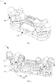
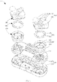
- FIG. 1 to FIG. 3 respectively show a schematic three-dimensional diagram of a massage device 1, a schematic cross-sectional view of the massage device 1 in one direction, and a schematic exploded diagram of the massage device 1 in one direction according to an embodiment of the present application.
- the massage device 1 includes a base 100, a driving module 200, a massage head 300, an enclosure 400, and a heating module 500.
- the base 100 is a supporting and mounting structure for the foregoing structures.
- the driving module 200 is mounted on the base 100 and is a driving structure of the massage head 300 for driving the massage head 300 to rotate.
- the massage head 300 is connected to the driving module 200 so as to be driven by the driving module 200 to rotate relative to the base 100.
- a side of the massage head 300 away from the base 100 is provided with a massage protrusion 310, and a first cavity 301 is formed on a side of the massage head 300 facing the base.
- the enclosure 400 is arranged on the base 100 and is located between the base 100 and the massage head 300.
- a free end of the enclosure 400 away from the base 100 extends into the first cavity 301, and an outer wall of the free end is arranged close to an inner wall of the massage head 300.
- a second cavity 401 in communication with the first cavity 301 is formed in the enclosure 400, and the second cavity 401 and the first cavity 301 jointly form a heating chamber.
- the heating module 500 is accommodated in the heating chamber and fixed relative to the base 100, and is configured to provide thermotherapy from the massage device 1 to a user's body parts such as neck and waist.
- a specific structure of the massage device 1 the following describes specific structures of the base 100, the massage head 300, the enclosure 400, the heating module 500, and the driving module 200 in sequence.
- the base 100 has a box-like structure as a whole, and is provided with an accommodating cavity 101 for accommodating at least a part of the driving module 200.
- the base 100 includes an upper housing 110 and a lower housing 120, and the upper housing 110 and the lower housing 120 jointly form the accommodating cavity 101.
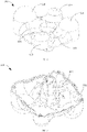
- FIG. 4 and FIG. 5 respectively show schematic three-dimensional diagrams of the massage head 300 in two directions.
- the massage head 300 is a structure that applies force to a user through rotation, so that the user experiences a massage effect.
- An end of the massage head 300 away from the base 100 is provided with a massage protrusion 310 for applying force to the user during the rotation of the massage head 300; and an end of the massage head 300 facing the base 100 defines a first cavity 301.
- the massage head 300 includes a plurality of massage protrusions 310, and the massage protrusions 310 are connected and fixed through a connecting portion 320.
- the massage head 300 includes four massage protrusions 310, and the massage protrusions 310 are respectively arranged at four corners of the connecting portion 320.
- the massage protrusions 310 in the massage head 300 is different from the rest of the massage protrusions 310; and the "difference" may be a difference in shape or a difference in volume.
- the massage device 1 includes two massage heads 300, and the two massage heads 300 are arranged on the same side of the base 100 at intervals.
- the enclosure 400 is arranged between the base 100 and the massage head 300, and includes a bottom plate 410 and a side wall 420.
- the bottom plate 410 is fixed on an outer surface of the base 100.
- the side wall 420 extends from an edge of the bottom plate 410 toward the massage head 300, a free end of the side wall 420 extends into the first cavity 301, and the side wall 420 and the bottom plate 410 jointly form a second cavity 401.
- the second cavity 401 is in communication with the first cavity 301, which forms a heating chamber together with the first cavity 301.
- the heating module 500 is accommodated in the heating chamber to reduce a waste caused by direct escape of heat generated by the heating module 500 into the air from a gap between the massage head 300 and the base 100.
- an outer wall of the free end of the enclosure 400 extending into the first cavity 301 is arranged close to an inner wall of the massage head 300, so as to reduce a rate of escape of heat generated by the heating module 500 from the heating chamber through a gap between the enclosure 400 and the massage head 300, and at the same time, to prevent the massage head 300 from rubbing against the enclosure 400 during the rotation.
- a fitting gap between the outer wall of the free end of the enclosure 400 and the inner wall of the massage head 300 is relatively small, and is usually controlled within 3 millimeters (mm).
- the fitting gap is less than 2 mm.
- the fitting gap is 1 mm.
- the enclosure 400 and the base 100 are formed separately, and are fixedly connected through screwing, clamping, etc. It can be understood that in other embodiments of the present application, the enclosure 400 may alternatively be integrally formed with the base 100.
- the heating module 500 For the heating module 500, references are made to FIG. 3 and other drawings.
- the heating module 500, the massage head 300, and the enclosure 400 are in one-to-one correspondence.
- the heating module 500 is specifically accommodated in the second cavity 401, and includes a circuit board 510 and a heating element 520.
- the heating element 520 is mounted on the circuit board 510, and is electrically connected to the circuit board 510.
- the enclosure 400 further includes a plurality of supporting ribs 430.
- the supporting ribs 430 are accommodated in the second cavity 401. One end of the supporting rib is fixed to the bottom plate 410 and the other end of the supporting rib extends toward the massage head 300.
- the supporting ribs 430 are distributed in a circular array around a rotation axis of the massage head 300.
- the circuit board 510 is in a ring shape arranged around a driving shaft 210, and is carried on the supporting ribs 430 and fixed to the supporting ribs 430.
- the heating element 520 is fixed on a side of the circuit board 510 away from the bottom plate 410, and is configured to generate heat when energized, so as to heat the massage head 300.
- the heating element 520 can heat various parts of the massage head 300 to ensure that temperatures of various areas of the massage head 300 are basically the same.
- the heating element 520 includes a miniature tungsten lamp, which is an element that can emit light and generate heat when energized, and can be purchased directly on the market. It can be understood that in other embodiments of the present application, the heating element may alternatively be another element such as a heating wire, provided that it can generate heat when energized.
- the heating module 500 specifically includes a plurality of heating elements 520, and the heating elements 520 are distributed in a circular array around the rotation axis of the massage head 300.
- the massage head 300 is provided with a number of heat-permeable holes 302.
- the heat-permeable hole 302 is arranged through the massage head 300 to communicate the first cavity 301 with an external environment of the massage head 300.
- the driving module 200 includes a driving shaft 210 and a power assembly 220.
- the driving shaft 210 is connected to the massage head 300 in one-to-one correspondence.
- the power assembly 220 is connected to each driving shaft 210, and the power assembly 220 is configured to drive the driving shaft 210 to rotate, so that the massage head 300 is driven by the driving shaft 210 to rotate relative to the base 100.
- the driving shaft 210 is rotatably mounted on the base 100; a part of the driving shaft 210 is accommodated in the accommodating cavity 101; and a part of the driving shaft 210 extends out of the base 100, then passes through the bottom plate 410 of the enclosure 400, and extends into the second cavity 401.
- the massage head 300 is fixed to the part of the driving shaft 210 extending into the second cavity 401, so as to be rotatably mounted on the base 100.
- a middle position of the massage head 300 extends toward the base 100 to form a mounting portion 330; and the mounting portion 330 has a cylindrical shape, at least partially extends into the second cavity 401, and is connected to the driving shaft 210.
- the mounting portion 330 is detachably connected to the driving shaft 210 through threading, interference fitting, etc.
- the power assembly 220 is separately connected to the two driving shafts 210 described above.
- the power assembly 220 includes a driving motor (not shown in the figure) and two transmission modules (not shown in the figure).
- the driving motor is separately connected to the two transmission modules, and a transmission module is correspondingly connected to a driving shaft 210, so that the massage device 1 can drive, through the driving motor, the driving shaft 210 to rotate, and then drive the corresponding massage head 300 to rotate.
- rotation directions of the two driving shafts 210 are opposite, so that the two massage heads 300 can squeeze a user's muscles toward each other during operation, so as to achieve a better massage effect.
- the transmission module includes a gear group.
- the transmission module may alternatively be another mechanism capable of implementing rotational output.
- the transmission module may further include a synchronous belt mechanism, or may include both a gear group and a synchronous belt mechanism.
- the driving module 200 may alternatively have another structural form, provided that it is connected to the massage head 300 and can drive the massage head 300 to rotate.
- the driving module 200 includes only two driving motors, and one driving motor is correspondingly connected to one massage head 300.
- the driving module 200 includes a driving motor and a transmission module, the driving motor is directly connected to one massage head 300 and the transmission module, and the other massage head 300 is connected to the transmission module. Specific structures of the driving module 200 are not listed one by one in the present application.
- the massage device 1 further includes a control circuit board (not shown in the figure) for controlling the heating of the heating module 500 and controlling the operation of the driving module 200.
- the control circuit board is a main control module of the massage device 1, and is accommodated in the accommodating cavity 101; and the heating module 500 and the driving module 200 are both connected to the control circuit board.
- the massage device 1 provided in the embodiments of the present application includes a base 100, a driving module 200, a massage head 300, an enclosure 400, and a heating module 500.
- a side of the massage head 300 away from the base 100 is provided with a massage protrusion 310, and a first cavity 301 is formed on a side of the massage head 300 facing the base 100.
- the driving module 200 is connected to the massage head 300 and configured to drive the massage head 300 to rotate.
- the enclosure 400 is arranged between the base 100 and the massage head 300, a free end of the enclosure 400 away from the base 100 extends into the first cavity 301, the enclosure 400 defines a second cavity 401 in communication with the first cavity 301, and the second cavity 401 and the first cavity 301 form a heating chamber.
- the heating module 500 is accommodated in the heating chamber and fixed relative to the base 100, and is configured to provide thermotherapy from the massage device 1 to a part of a human body.
- the heating module 500 is arranged to be fixed relative to the base 100, so that the heating module 500 in the massage device 1 is connected to the control circuit board without using a brush and a ring-shaped conductive plate. Therefore, the massage device 1 provided in the embodiments of the present application can solve the problem that a heating module of the existing massage device on the market cannot work continuously and stably due to poor contact between a brush and a conductive copper ring.
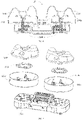
- FIG. 6 and FIG. 7 show a schematic cross-sectional view and a schematic exploded diagram of a massage device 1B in one direction according to another embodiment of the present application.
- the massage device 1B includes a base 100B, a driving module 200B, a massage head 300B, an enclosure 400B, and a heating module 500B.
- References are made to FIG. 2 , and main differences between the massage device 1B and the massage device 1 in the first embodiment are as follows: The free end of the enclosure 400 of the massage device 1 away from the base 100 extends into the first cavity 301, and the outer wall of the free end is arranged close to the inner wall of the massage head 300.
- an open end of the massage head 300B facing the base 100B extends into the enclosure 400B, an outer wall of the open end is arranged close to an inner wall of the enclosure 400B, and an outer diameter of the open end of the massage head 300B is slightly smaller than an inner diameter of the inner wall of the enclosure 400B.
- a difference between the outer diameter of the open end of the massage head 300B and the inner diameter of the inner wall of the enclosure 400B can be controlled within 3 millimeters (mm). For example, the difference is less than 2 mm. For another example, the difference is 1 mm.
- the end of the massage head 300B facing the base 100B is an open end, and the open end is in communication with a first cavity 301B;
- the enclosure 400B includes a bottom plate 410B and a side wall 420B;
- the bottom plate 410B is fixed on an outer surface of the base 100B;
- the side wall 420B extends from an edge of the bottom plate 410B toward the massage head 300B; and
- the side wall 420B and the bottom plate 410B jointly form a second cavity 401B.
- the open end of the massage head 300B extends into the end of the enclosure 400B away from the base 100B, and the outer wall of the open end is arranged close to the inner wall of the side wall 420B.
- the second cavity 401B is in communication with the first cavity 301B through the open end of the massage head 300B, and the second cavity 401B and the first cavity 301B jointly form a heating chamber.
- the heating module 500B is accommodated in the second cavity 401B, and can heat the massage head 300B when the massage device 1B is working. Because the heating module 500B is fixed relative to the base 100B, and the massage head 300B rotates above the heating element 520, the continuous and stable operation of the heating module 500B can be ensured.
- the open end of the massage head 300B may not extend into the enclosure 400B, but is arranged above the enclosure 400B. In this case, there is an up-and-down gap between the open end of the massage head 300B and the end of the enclosure 400B away from the base 100B. Likewise, the gap is controlled within 3 millimeters (mm) to reduce a rate of escape of heat generated by the heating module 500B from the heating chamber through a gap between the enclosure 400B and the massage head 300B, and at the same time, to prevent the massage head 300B from rubbing against the enclosure 400B during the rotation.
- mm millimeters
Landscapes
- Health & Medical Sciences (AREA)
- Epidemiology (AREA)
- Pain & Pain Management (AREA)
- Physical Education & Sports Medicine (AREA)
- Rehabilitation Therapy (AREA)
- Life Sciences & Earth Sciences (AREA)
- Animal Behavior & Ethology (AREA)
- General Health & Medical Sciences (AREA)
- Public Health (AREA)
- Veterinary Medicine (AREA)
- Engineering & Computer Science (AREA)
- Bioinformatics & Cheminformatics (AREA)
- Dermatology (AREA)
- Massaging Devices (AREA)
- Percussion Or Vibration Massage (AREA)
Applications Claiming Priority (1)
| Application Number | Priority Date | Filing Date | Title |
|---|---|---|---|
| CN202120234243.7U CN217014405U (zh) | 2021-01-27 | 2021-01-27 | 按摩装置 |
Publications (3)
| Publication Number | Publication Date |
|---|---|
| EP4035643A1 true EP4035643A1 (de) | 2022-08-03 |
| EP4035643B1 EP4035643B1 (de) | 2024-03-13 |
| EP4035643C0 EP4035643C0 (de) | 2024-03-13 |
Family
ID=75936685
Family Applications (1)
| Application Number | Title | Priority Date | Filing Date |
|---|---|---|---|
| EP21173639.2A Active EP4035643B1 (de) | 2021-01-27 | 2021-05-12 | Massagevorrichtung |
Country Status (5)
| Country | Link |
|---|---|
| US (1) | US11911334B2 (de) |
| EP (1) | EP4035643B1 (de) |
| JP (1) | JP7135158B2 (de) |
| CN (1) | CN217014405U (de) |
| DE (1) | DE202021102250U1 (de) |
Citations (4)
| Publication number | Priority date | Publication date | Assignee | Title |
|---|---|---|---|---|
| EP2022460A1 (de) * | 2007-08-09 | 2009-02-11 | Shifeng Yuan | Erwärmbarer Massagekopf |
| WO2014059595A1 (zh) * | 2012-10-16 | 2014-04-24 | 翔天电子实业有限公司 | 具有甩动与揉捏按摩功能的按摩器 |
| CN209075395U (zh) * | 2018-03-28 | 2019-07-09 | 东莞市固豪塑胶五金制品有限公司 | 发热按摩枕 |
| KR20190115403A (ko) * | 2018-04-02 | 2019-10-11 | 주식회사 스타쇼핑 | 여행용 안마 베개 |
Family Cites Families (8)
| Publication number | Priority date | Publication date | Assignee | Title |
|---|---|---|---|---|
| US20060129072A1 (en) * | 2004-12-10 | 2006-06-15 | Shin Thomas J | Far infra-red ray and anion emitting thermal rotary massage device for decreasing the fat in the abdominal region of a human body |
| JP2008289616A (ja) | 2007-05-23 | 2008-12-04 | Twinbird Corp | マッサージ装置 |
| JP2011172632A (ja) | 2010-02-23 | 2011-09-08 | Panasonic Electric Works Co Ltd | 頭皮ケア装置 |
| US20120010544A1 (en) * | 2010-07-07 | 2012-01-12 | St Life Co., Ltd. | Kneading massage device |
| US8979779B2 (en) * | 2012-03-14 | 2015-03-17 | Listore International Co., Ltd. | Left and right movable massage device |
| CN205268526U (zh) * | 2015-11-16 | 2016-06-01 | 漳州蒙发利实业有限公司 | 一种舒适型按摩头及按摩器 |
| CN211705283U (zh) * | 2019-12-19 | 2020-10-20 | 厦门睿康科技有限公司 | 一种脚部按摩器 |
| CN213076458U (zh) * | 2020-04-02 | 2021-04-30 | 厦门市蒙泰健康科技有限公司 | 一种揉捏按摩机芯 |
-
2021
- 2021-01-27 CN CN202120234243.7U patent/CN217014405U/zh active Active
- 2021-04-26 US US17/239,687 patent/US11911334B2/en active Active
- 2021-04-27 DE DE202021102250.7U patent/DE202021102250U1/de active Active
- 2021-05-07 JP JP2021079234A patent/JP7135158B2/ja active Active
- 2021-05-12 EP EP21173639.2A patent/EP4035643B1/de active Active
Patent Citations (4)
| Publication number | Priority date | Publication date | Assignee | Title |
|---|---|---|---|---|
| EP2022460A1 (de) * | 2007-08-09 | 2009-02-11 | Shifeng Yuan | Erwärmbarer Massagekopf |
| WO2014059595A1 (zh) * | 2012-10-16 | 2014-04-24 | 翔天电子实业有限公司 | 具有甩动与揉捏按摩功能的按摩器 |
| CN209075395U (zh) * | 2018-03-28 | 2019-07-09 | 东莞市固豪塑胶五金制品有限公司 | 发热按摩枕 |
| KR20190115403A (ko) * | 2018-04-02 | 2019-10-11 | 주식회사 스타쇼핑 | 여행용 안마 베개 |
Also Published As
| Publication number | Publication date |
|---|---|
| US20220233398A1 (en) | 2022-07-28 |
| CN217014405U (zh) | 2022-07-22 |
| JP7135158B2 (ja) | 2022-09-12 |
| EP4035643B1 (de) | 2024-03-13 |
| JP2022115035A (ja) | 2022-08-08 |
| EP4035643C0 (de) | 2024-03-13 |
| US11911334B2 (en) | 2024-02-27 |
| DE202021102250U1 (de) | 2021-05-03 |
Similar Documents
| Publication | Publication Date | Title |
|---|---|---|
| HK1195196A2 (zh) | 脸部用的按摩装置 | |
| KR20000043488A (ko) | 전자식 안마기 | |
| KR20170003668U (ko) | 복합 미용기기 | |
| KR102396622B1 (ko) | 미용기기 | |
| US20210059396A1 (en) | Handheld multifunctional facial cleansing brush structure | |
| CN109394503A (zh) | 多功能美容仪及其使用方法 | |
| KR100677863B1 (ko) | 맛사지장치 | |
| CN217472368U (zh) | 多功能按摩仪及其按摩控制系统 | |
| EP4035643A1 (de) | Massagevorrichtung | |
| US20240148600A1 (en) | Massage device | |
| KR20170032051A (ko) | 마스크팩 냉온열장치 | |
| CN216485800U (zh) | 一种vr眼镜的散热结构 | |
| CN215425979U (zh) | 一种多功能的按摩飞碟 | |
| CN110393662B (zh) | 一种护眼仪 | |
| CN109998893B (zh) | 一种多功能美容仪 | |
| KR200395180Y1 (ko) | 맛사지장치 | |
| CN219208015U (zh) | 一种多功能美容仪 | |
| CN209884483U (zh) | 一种冷热发生器及美容仪 | |
| CN223248494U (zh) | 按摩器 | |
| KR102840538B1 (ko) | 피부 미용기기 | |
| JP7144792B1 (ja) | 美容電動ブラシ装置 | |
| CN222854449U (zh) | 按摩器的按摩头装配结构及按摩器 | |
| CN219763907U (zh) | 头部理疗仪 | |
| CN217186942U (zh) | 颈部按摩仪 | |
| CN217724065U (zh) | 吊坠和吊坠式按摩仪 |
Legal Events
| Date | Code | Title | Description |
|---|---|---|---|
| PUAI | Public reference made under article 153(3) epc to a published international application that has entered the european phase |
Free format text: ORIGINAL CODE: 0009012 |
|
| STAA | Information on the status of an ep patent application or granted ep patent |
Free format text: STATUS: REQUEST FOR EXAMINATION WAS MADE |
|
| 17P | Request for examination filed |
Effective date: 20210512 |
|
| AK | Designated contracting states |
Kind code of ref document: A1 Designated state(s): AL AT BE BG CH CY CZ DE DK EE ES FI FR GB GR HR HU IE IS IT LI LT LU LV MC MK MT NL NO PL PT RO RS SE SI SK SM TR |
|
| GRAP | Despatch of communication of intention to grant a patent |
Free format text: ORIGINAL CODE: EPIDOSNIGR1 |
|
| STAA | Information on the status of an ep patent application or granted ep patent |
Free format text: STATUS: GRANT OF PATENT IS INTENDED |
|
| RIC1 | Information provided on ipc code assigned before grant |
Ipc: A61H 7/00 20060101ALI20231127BHEP Ipc: A61H 15/00 20060101ALI20231127BHEP Ipc: A61H 15/02 20060101AFI20231127BHEP |
|
| INTG | Intention to grant announced |
Effective date: 20231218 |
|
| GRAS | Grant fee paid |
Free format text: ORIGINAL CODE: EPIDOSNIGR3 |
|
| GRAA | (expected) grant |
Free format text: ORIGINAL CODE: 0009210 |
|
| STAA | Information on the status of an ep patent application or granted ep patent |
Free format text: STATUS: THE PATENT HAS BEEN GRANTED |
|
| AK | Designated contracting states |
Kind code of ref document: B1 Designated state(s): AL AT BE BG CH CY CZ DE DK EE ES FI FR GB GR HR HU IE IS IT LI LT LU LV MC MK MT NL NO PL PT RO RS SE SI SK SM TR |
|
| REG | Reference to a national code |
Ref country code: GB Ref legal event code: FG4D |
|
| REG | Reference to a national code |
Ref country code: CH Ref legal event code: EP |
|
| REG | Reference to a national code |
Ref country code: DE Ref legal event code: R096 Ref document number: 602021010274 Country of ref document: DE |
|
| REG | Reference to a national code |
Ref country code: IE Ref legal event code: FG4D |
|
| U01 | Request for unitary effect filed |
Effective date: 20240322 |
|
| U07 | Unitary effect registered |
Designated state(s): AT BE BG DE DK EE FI FR IT LT LU LV MT NL PT SE SI Effective date: 20240402 |
|
| U20 | Renewal fee for the european patent with unitary effect paid |
Year of fee payment: 4 Effective date: 20240425 |
|
| PG25 | Lapsed in a contracting state [announced via postgrant information from national office to epo] |
Ref country code: GR Free format text: LAPSE BECAUSE OF FAILURE TO SUBMIT A TRANSLATION OF THE DESCRIPTION OR TO PAY THE FEE WITHIN THE PRESCRIBED TIME-LIMIT Effective date: 20240614 |
|
| PG25 | Lapsed in a contracting state [announced via postgrant information from national office to epo] |
Ref country code: HR Free format text: LAPSE BECAUSE OF FAILURE TO SUBMIT A TRANSLATION OF THE DESCRIPTION OR TO PAY THE FEE WITHIN THE PRESCRIBED TIME-LIMIT Effective date: 20240313 Ref country code: RS Free format text: LAPSE BECAUSE OF FAILURE TO SUBMIT A TRANSLATION OF THE DESCRIPTION OR TO PAY THE FEE WITHIN THE PRESCRIBED TIME-LIMIT Effective date: 20240613 |
|
| PG25 | Lapsed in a contracting state [announced via postgrant information from national office to epo] |
Ref country code: ES Free format text: LAPSE BECAUSE OF FAILURE TO SUBMIT A TRANSLATION OF THE DESCRIPTION OR TO PAY THE FEE WITHIN THE PRESCRIBED TIME-LIMIT Effective date: 20240313 |
|
| PG25 | Lapsed in a contracting state [announced via postgrant information from national office to epo] |
Ref country code: RS Free format text: LAPSE BECAUSE OF FAILURE TO SUBMIT A TRANSLATION OF THE DESCRIPTION OR TO PAY THE FEE WITHIN THE PRESCRIBED TIME-LIMIT Effective date: 20240613 Ref country code: NO Free format text: LAPSE BECAUSE OF FAILURE TO SUBMIT A TRANSLATION OF THE DESCRIPTION OR TO PAY THE FEE WITHIN THE PRESCRIBED TIME-LIMIT Effective date: 20240613 Ref country code: HR Free format text: LAPSE BECAUSE OF FAILURE TO SUBMIT A TRANSLATION OF THE DESCRIPTION OR TO PAY THE FEE WITHIN THE PRESCRIBED TIME-LIMIT Effective date: 20240313 Ref country code: GR Free format text: LAPSE BECAUSE OF FAILURE TO SUBMIT A TRANSLATION OF THE DESCRIPTION OR TO PAY THE FEE WITHIN THE PRESCRIBED TIME-LIMIT Effective date: 20240614 Ref country code: ES Free format text: LAPSE BECAUSE OF FAILURE TO SUBMIT A TRANSLATION OF THE DESCRIPTION OR TO PAY THE FEE WITHIN THE PRESCRIBED TIME-LIMIT Effective date: 20240313 |
|
| PG25 | Lapsed in a contracting state [announced via postgrant information from national office to epo] |
Ref country code: IS Free format text: LAPSE BECAUSE OF FAILURE TO SUBMIT A TRANSLATION OF THE DESCRIPTION OR TO PAY THE FEE WITHIN THE PRESCRIBED TIME-LIMIT Effective date: 20240713 |
|
| PG25 | Lapsed in a contracting state [announced via postgrant information from national office to epo] |
Ref country code: SM Free format text: LAPSE BECAUSE OF FAILURE TO SUBMIT A TRANSLATION OF THE DESCRIPTION OR TO PAY THE FEE WITHIN THE PRESCRIBED TIME-LIMIT Effective date: 20240313 |
|
| PG25 | Lapsed in a contracting state [announced via postgrant information from national office to epo] |
Ref country code: CZ Free format text: LAPSE BECAUSE OF FAILURE TO SUBMIT A TRANSLATION OF THE DESCRIPTION OR TO PAY THE FEE WITHIN THE PRESCRIBED TIME-LIMIT Effective date: 20240313 |
|
| PG25 | Lapsed in a contracting state [announced via postgrant information from national office to epo] |
Ref country code: PL Free format text: LAPSE BECAUSE OF FAILURE TO SUBMIT A TRANSLATION OF THE DESCRIPTION OR TO PAY THE FEE WITHIN THE PRESCRIBED TIME-LIMIT Effective date: 20240313 |
|
| PG25 | Lapsed in a contracting state [announced via postgrant information from national office to epo] |
Ref country code: SK Free format text: LAPSE BECAUSE OF FAILURE TO SUBMIT A TRANSLATION OF THE DESCRIPTION OR TO PAY THE FEE WITHIN THE PRESCRIBED TIME-LIMIT Effective date: 20240313 |
|
| PG25 | Lapsed in a contracting state [announced via postgrant information from national office to epo] |
Ref country code: SM Free format text: LAPSE BECAUSE OF FAILURE TO SUBMIT A TRANSLATION OF THE DESCRIPTION OR TO PAY THE FEE WITHIN THE PRESCRIBED TIME-LIMIT Effective date: 20240313 Ref country code: SK Free format text: LAPSE BECAUSE OF FAILURE TO SUBMIT A TRANSLATION OF THE DESCRIPTION OR TO PAY THE FEE WITHIN THE PRESCRIBED TIME-LIMIT Effective date: 20240313 Ref country code: RO Free format text: LAPSE BECAUSE OF FAILURE TO SUBMIT A TRANSLATION OF THE DESCRIPTION OR TO PAY THE FEE WITHIN THE PRESCRIBED TIME-LIMIT Effective date: 20240313 Ref country code: PL Free format text: LAPSE BECAUSE OF FAILURE TO SUBMIT A TRANSLATION OF THE DESCRIPTION OR TO PAY THE FEE WITHIN THE PRESCRIBED TIME-LIMIT Effective date: 20240313 Ref country code: IS Free format text: LAPSE BECAUSE OF FAILURE TO SUBMIT A TRANSLATION OF THE DESCRIPTION OR TO PAY THE FEE WITHIN THE PRESCRIBED TIME-LIMIT Effective date: 20240713 Ref country code: CZ Free format text: LAPSE BECAUSE OF FAILURE TO SUBMIT A TRANSLATION OF THE DESCRIPTION OR TO PAY THE FEE WITHIN THE PRESCRIBED TIME-LIMIT Effective date: 20240313 |
|
| REG | Reference to a national code |
Ref country code: DE Ref legal event code: R097 Ref document number: 602021010274 Country of ref document: DE |
|
| REG | Reference to a national code |
Ref country code: CH Ref legal event code: PL |
|
| PG25 | Lapsed in a contracting state [announced via postgrant information from national office to epo] |
Ref country code: MC Free format text: LAPSE BECAUSE OF FAILURE TO SUBMIT A TRANSLATION OF THE DESCRIPTION OR TO PAY THE FEE WITHIN THE PRESCRIBED TIME-LIMIT Effective date: 20240313 |
|
| PLBE | No opposition filed within time limit |
Free format text: ORIGINAL CODE: 0009261 |
|
| STAA | Information on the status of an ep patent application or granted ep patent |
Free format text: STATUS: NO OPPOSITION FILED WITHIN TIME LIMIT |
|
| PG25 | Lapsed in a contracting state [announced via postgrant information from national office to epo] |
Ref country code: MC Free format text: LAPSE BECAUSE OF FAILURE TO SUBMIT A TRANSLATION OF THE DESCRIPTION OR TO PAY THE FEE WITHIN THE PRESCRIBED TIME-LIMIT Effective date: 20240313 Ref country code: CH Free format text: LAPSE BECAUSE OF NON-PAYMENT OF DUE FEES Effective date: 20240531 |
|
| 26N | No opposition filed |
Effective date: 20241216 |
|
| PG25 | Lapsed in a contracting state [announced via postgrant information from national office to epo] |
Ref country code: IE Free format text: LAPSE BECAUSE OF NON-PAYMENT OF DUE FEES Effective date: 20240512 |
|
| U20 | Renewal fee for the european patent with unitary effect paid |
Year of fee payment: 5 Effective date: 20250425 |
|
| PG25 | Lapsed in a contracting state [announced via postgrant information from national office to epo] |
Ref country code: CY Free format text: LAPSE BECAUSE OF FAILURE TO SUBMIT A TRANSLATION OF THE DESCRIPTION OR TO PAY THE FEE WITHIN THE PRESCRIBED TIME-LIMIT; INVALID AB INITIO Effective date: 20210512 |
|
| PG25 | Lapsed in a contracting state [announced via postgrant information from national office to epo] |
Ref country code: HU Free format text: LAPSE BECAUSE OF FAILURE TO SUBMIT A TRANSLATION OF THE DESCRIPTION OR TO PAY THE FEE WITHIN THE PRESCRIBED TIME-LIMIT; INVALID AB INITIO Effective date: 20210512 |
|
| U1N | Appointed representative for the unitary patent procedure changed after the registration of the unitary effect |
Representative=s name: SANTARELLI; FR |