EP4035611B1 - Verstellbarer schneideblock für kniearthroplastie - Google Patents
Verstellbarer schneideblock für kniearthroplastie Download PDFInfo
- Publication number
- EP4035611B1 EP4035611B1 EP21179444.1A EP21179444A EP4035611B1 EP 4035611 B1 EP4035611 B1 EP 4035611B1 EP 21179444 A EP21179444 A EP 21179444A EP 4035611 B1 EP4035611 B1 EP 4035611B1
- Authority
- EP
- European Patent Office
- Prior art keywords
- actuator
- base
- insert
- cam
- cut guide
- Prior art date
- Legal status (The legal status is an assumption and is not a legal conclusion. Google has not performed a legal analysis and makes no representation as to the accuracy of the status listed.)
- Active
Links
Images


Classifications
-
- A—HUMAN NECESSITIES
- A61—MEDICAL OR VETERINARY SCIENCE; HYGIENE
- A61B—DIAGNOSIS; SURGERY; IDENTIFICATION
- A61B17/00—Surgical instruments, devices or methods
- A61B17/16—Instruments for performing osteoclasis; Drills or chisels for bones; Trepans
- A61B17/17—Guides or aligning means for drills, mills, pins or wires
- A61B17/1739—Guides or aligning means for drills, mills, pins or wires specially adapted for particular parts of the body
- A61B17/1764—Guides or aligning means for drills, mills, pins or wires specially adapted for particular parts of the body for the knee
-
- A—HUMAN NECESSITIES
- A61—MEDICAL OR VETERINARY SCIENCE; HYGIENE
- A61B—DIAGNOSIS; SURGERY; IDENTIFICATION
- A61B17/00—Surgical instruments, devices or methods
- A61B17/14—Surgical saws
- A61B17/15—Guides therefor
- A61B17/154—Guides therefor for preparing bone for knee prosthesis
- A61B17/155—Cutting femur
-
- A—HUMAN NECESSITIES
- A61—MEDICAL OR VETERINARY SCIENCE; HYGIENE
- A61B—DIAGNOSIS; SURGERY; IDENTIFICATION
- A61B17/00—Surgical instruments, devices or methods
- A61B17/16—Instruments for performing osteoclasis; Drills or chisels for bones; Trepans
- A61B17/164—Instruments for performing osteoclasis; Drills or chisels for bones; Trepans intramedullary
-
- A—HUMAN NECESSITIES
- A61—MEDICAL OR VETERINARY SCIENCE; HYGIENE
- A61B—DIAGNOSIS; SURGERY; IDENTIFICATION
- A61B17/00—Surgical instruments, devices or methods
- A61B2017/00367—Details of actuation of instruments, e.g. relations between pushing buttons, or the like, and activation of the tool, working tip, or the like
Definitions
- the present subject matter relates to systems used in knee arthroplasties.
- the closest prior art is document US 2016/015399 A1 , which defines the preamble of claim 1.
- a knee arthroplasty can be used to restore natural knee function by repairing damaged or diseased articular surfaces of the femur and/or tibia.
- An incision is made into the knee joint to expose the bones comprising the joint.
- Cut guides are used to guide the removal of the articular surfaces that are to be replaced.
- Prostheses are used to replicate the articular surfaces.
- Knee prostheses can include a femoral component implanted on the distal end of the femur, which articulates with a tibial bearing component and a tibial component implanted on the proximal end of a tibia to replicate the function of a healthy natural knee.
- Various types of arthroplasties are known including a total knee arthroplasty, where all of the articulating compartments of the joint are repaired with prosthetic components.
- This disclosure pertains generally to knee prostheses, systems, and methods for a knee arthroplasty and/or as part of a knee revision surgery.
- the present inventors have recognized, among other things, that patients requiring knee arthroplasties can have femurs of varying qualities, such as size, density, and condition/health. Because of these variations, location and depth of cuts performed on the bones may vary relatively dramatically between patients. Because it may be expensive to match cutting guide specific to each patient, a system that is adjustable is desired to guide a bone cut for a variety of patients.
- the present inventors propose a cutting block that can be quickly and easily adjusted (and readjusted) to select a cutting location as desired.
- the present invention provides an adjustable cut guide, as defined in claim 1. Further optional features of the invention are defined in the dependent claims. Methods are described herein but the methods are not claimed.
- the insert may further comprise a rack including rack teeth; and the actuator further comprises teeth engageable with the rack teeth to secure the insert to the base when the actuator is in the extended position.
- the teeth of the actuator may disengage the rack teeth when the actuator is in the retracted position such that the base is free to move relative to the insert.
- the channel may further comprise: a track configured to receive the rack of the insert, wherein the actuator teeth extend into the track to engage the rack when the actuator is in the extended position.
- a biasing element is included which engages the actuator and the base within the slot, the biasing element biasing the actuator to an extended position and the cam to the first position.
- the actuator further comprises a leg extending away from the cam into an anti-rotation slot of the block, the leg translatable in the slot with the actuator and the slot limiting rotation of the leg about an axis of the actuator.
- the cut guide may further comprise: a plurality of bores extending through the base substantially parallel to the intramedullary bore.
- the channel is configured to accept a plurality of inserts including the insert, wherein each of the plurality of inserts comprises an intramedullary rod bore having a rod angle between 1 degree and 9 degrees.
- the cut guide may be an anterior/posterior cutting block for resection of a distal portion of a femur.
- the body may further comprise: a plurality of pin apertures extending through the body configured to receive pins therethrough to fixate the base to the bone.
- a method of inserting an intramedullary guide rod into a bone comprising: actuating a cam to retract an actuator; inserting an angle guide into a slot of the body of the guide; inserting an intramedullary rod through a bore of the angle guide and into an intramedullary cavity of the bone; and releasing the cam to extend the actuator to secure the angle guide relative to the body.
- the method includes translating the body relative to the intramedullary rod and the angle guide to anteriorly to posteriorly adjust the body relative to the bone.
- the method includes inserting one or more pins through pin apertures of the body to secure the body to the bone.
- the method includes coupling a ligament tensioner to the body; and operating the tensioner to set a ligament tension of a joint of the bone.
- the method includes coupling a cutting guide to the body; inserting a cutting blade through the guide to engage the bone; and operating the cutting blade to resect the bone.
- the method includes spacing an anterior cutting guide on an anterior portion of the bone by coupling an outrigger to the anterior cutting guide and to the body.
- the cutting block, assembly, or method is optionally configured such that all elements or options recited are available to use or select from.
- the present application relates to devices and methods for a knee arthroplasty, where a tibia and/or a femur are resected to receive prostheses to replace damaged or nonfunctioning components of a patient.
- proximal and distal should be given their generally understood anatomical interpretation.
- proximal refers to a direction generally toward the torso of a patient
- distal refers to the opposite direction of proximal, i.e., away from the torso of a patient. It should be understood that the use of the terms “proximal” and “distal” should be interpreted as though the patient were standing with the knee joint in extension despite the apparatuses described herein generally being used with the knee joint in flexion. The intent is to differentiate the terms “proximal” and “distal” from the terms “anterior” and “posterior”.
- anterior refers to a rear of the patient, e.g., a back of the knee.
- anterior refers to a front of the patient, e.g., a front of the knee.
- posterior refers to the opposite direction of “anterior”.
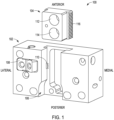
- FIG. 1 shows an isometric view of cutting guide assembly 100, in accordance with at least one example of the present disclosure.
- Cutting guide assembly 100 includes base 102 and insert 104.
- Base 102 includes channel 106, cam 108, and actuator 110.
- Insert 104 can include anterior intramedullary (IM) bore 112, posterior IM bore 114, and rack 116. Also shown in FIG. 1 are orientation indicators Anterior, Posterior, Medial, and Lateral.
- IM anterior intramedullary
- Base 102 and insert 104 can be rigid members comprised of materials such as plastics, metals, and combinations thereof.
- base 102 and insert 104 can be comprised of steel alloys.
- Insert 104 (or angle guide) can be insertable into base 102, as described further below.
- Channel 106 extends between an anterior portion and a posterior portion of base 102.
- Channel 106 is sized to receive insert 104 such that insert 104 can translate therein.
- Channel 106 can include an undercut or track (discussed further below) configured to receive rack 116 of insert 104.
- Cam 108 can be a rigid member comprised of materials such as metals, plastics, and combinations thereof. Cam 108 can be pivotably coupled to base 102 and can engage actuator 110. Actuator 110 can be a rigid member comprised of materials such as metals, plastics, and combinations thereof. Actuator 110 is disposed in a slot of base 102 (as discussed further below), where the slot intersects channel 106, such that actuator 110 can extend into channel 106 when actuator 110 is in a first position, as shown in FIG. 1 . Actuator 110 can include teeth configured to engage teeth of rack 116, as discussed further below.
- Insert 104 includes anterior IM bore 112 and posterior IM bore 114, where each bore can extend through the insert generally perpendicular to the anterior/posterior plane. Insert 104 can also include rack 116, which can be a rack type gear including teeth configured to extend from a medial and a lateral portion of insert 104 (only medial teeth visible in FIG. 1 ) to face medially and laterally, respectively.
- rack 116 can be a rack type gear including teeth configured to extend from a medial and a lateral portion of insert 104 (only medial teeth visible in FIG. 1 ) to face medially and laterally, respectively.
- cam 108 can be rotated clockwise (as shown further below) to retract actuator 110 into base 102. Insert 104 can then be inserted into channel 106 such that rack 116 is disposed in the track of channel 106. Cam 108 can then be released so that a biasing element within base 102 can force actuator 110 medially to enter the track of channel 106 to engage lateral teeth of insert 104. This engagement can secure the position of insert 104 relative to base 102.
- an intramedullary (IM) rod can be inserted through one of anterior IM bore 112 or posterior IM bore 114 to secure cutting guide assembly 100 to the IM rod and therefore the bone.
- IM intramedullary
- the IM rod can be aligned near posterior and anterior terminations of base 102.
- cutting guide assembly can be used for both left and right knees by rotating the insert about 180 degrees.
- cam 108 can be actuated again to allow base 102 to move relative to insert 104.
- Base 102 can be aligned with the bone and cam 108 can be again released, allowing actuator 110 to secure base 102 to insert 104 and therefore secure base 102 relative to the IM rod and the bone. The details of the operations are discussed below in further detail.
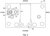
- FIG. 2 shows a plan view from a slightly anterior perspective of cutting guide assembly 100, in accordance with at least one example of the present disclosure.
- Cutting guide assembly 100 includes base 102, which can include channel 106, cam 108, actuator 110, cam pin 118, biasing element 120, and slot 122.
- Actuator 110 can include teeth 124. Also shown in FIG. 2 are orientation indicators Anterior, Posterior, Medial, and Lateral.
- Cutting guide assembly 100 can be consistent with the description of FIG. 1 above; however, FIG. 2 shows additional details of cutting guide assembly 100.
- cam 108 is shown as being coupled to base 102 by cam pin 118.
- Cam pin 118 can be a generally cylindrical rigid member comprised of materials such as metals, plastics, and combinations thereof.
- Cam pin 118 can be secured to base 102 at two respective ends and can pass through a bore of cam 108 to form a journal bearing about which cam 108 can rotate, in some examples.
- slot 122 which can house cam 108, actuator 110 and biasing element 120.
- slot 122 can be of multiple sizes where a larger portion can support actuator 108 and a smaller portion can support actuator 110 and biasing element 120. Slot 122 intersects with channel 106, as shown below in further detail.
- Biasing element 120 can be a resilient member configured to bias actuator 110 medially from slot 122 to extend partially into channel 106.
- biasing element 120 can be a compression spring, such as a coil compression spring or a wave spring.
- biasing element 120 can be other types of resilient members, such as a resilient plastic or rubber elements.
- actuator 110 which can be a rigid member extending most of the lateral to medial length of slot 122.
- Actuator 110 can also include teeth 124, which can be disposed at a medial termination of actuator 110 facing medially outward from actuator 110, such that teeth 124 can extend into channel 106 when actuator 110 is in the first position (as shown in FIG. 1 ) and can be retracted into slot 122 when actuator 110 is in the second position (as shown in FIG. 2 ).
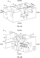
- FIG. 3A shows an isometric view of cutting guide assembly 100 in a first condition, in accordance with at least one example of the present disclosure.
- FIG. 3B shows a cross-section view of cutting guide assembly 100 across section 3B-3B of FIG. 3A in a first condition, in accordance with at least one example of the present disclosure.
- FIGS. 3A and 3B are discussed below concurrently.
- Cutting guide assembly 100 includes base 102 and insert 104 (only shown in FIG. 3A ).
- Base 102 includes channel 106, cam 108, actuator 110 (only shown in FIG. 3B ), cam pin 118 (only visible in FIG. 3B ), biasing element 120 (only visible in FIG. 3B ), slot 122, actuator bore 126 (only visible in FIG. 3B ), and actuator plug 128 (only visible in FIG. 3B ).
- Channel 106 can include track 130.
- Cam 108 can include bores 132 and notch 134.
- Actuator 110 can include teeth 124, cam arm 136 and alignment arm 138.
- Insert 104 can include rack 116. Also shown in FIGS. 3A and 3B are orientation indicators Anterior, Posterior, Medial, and Lateral.
- Cutting guide assembly 100 includes slot 122, which can extend through base 100 substantially perpendicular to the anterior-posterior plane.
- Slot 122 can be sized to support cam 108 and actuator 110.
- Actuator bore 126 can be a bore extending from a lateral termination of base 102, intersecting slot 122 and intersecting with and terminating at channel 106.
- actuator bore 126 can be sized to support actuator 110, biasing element 120, and actuator plug 128.
- Actuator plug 128 can be a rigid member disposed proximate a lateral termination of actuator bore 126. Actuator plug 128 can be configured to engage biasing element 120 and can be configured to retain biasing element 120 and therefore actuator 110 within actuator bore 126. In some examples, actuator plug 128 can be secured to base 102 in a threaded configuration, and can be pinned, compression fit, welded, and snap fit into actuator bore 126 in other examples.
- FIGS. 3A and 3B also show track 130 of channel 106, which can be an undercut extending medially and laterally into base 102.
- Track 130 can be sized to receive rack 116 of insert 104 (of FIG. 3A ) while allowing track 130, and therefore insert 104, to translate within channel 106 and track 130 when actuator 110 does not engage track 130.
- Cam 108 can include bores 132, which can extend through cam 108 providing cleaning and sterilization access to internal components of base 102, such as actuator plug 128, biasing element 120, slot 122, and actuator 110.
- Notch 134 can be a notch in cam 108 substantially facing actuator 110 and sized to receive cam arm 136 of actuator 110.
- Cam arm 136 can be a rigid protrusion extending towards cam 108 from actuator 110 and can be configured to engage notch 134 of cam 108.
- Alignment arm 138 can extend opposite of cam arm 136 from actuator 110 and can terminate prior to extending past base 102. Alignment arm 138 can be sized to fit within slot 122 but sized to engage the walls of channel 122 to reduce rotation of actuator 110 relative to actuator bore 126, helping to ensure that teeth 124 of actuator 110 remain aligned with teeth of track 116.
- teeth 124 can be disposed at a medial termination of actuator 110, as described above, and can extend into track 130 to engage teeth of rack 116 when actuator 110 is in a first position, as shown in FIGS. 3A and 3B . Because biasing element 120 applies a force to plug 128 and actuator 110, biasing element 120 biases teeth 124 to extend into track 116. Also, because cam arm 136 engages cam 108 at notch 134 of cam 108, biasing element 120 biases cam 108 into the first position as shown in FIGS. 3A and 3B .
- teeth 124 of actuator 110 help prevent translation of insert 104 within slot 106
- engagement of rack 116 with surfaces of track 130 and engagement of other portion of insert 104 with surfaces of channel 106 reduce translation or rotation of insert 104 relative to base 102 in any other direction.
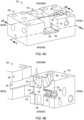
- FIG. 4A shows an isometric view of cutting block assembly 100 in a second condition, in accordance with at least one example of the present disclosure.
- FIG. 4B shows a cross-section view of cutting guide assembly 100 across section 4B-4B of FIG. 4A in a second condition, in accordance with at least one example of the present disclosure.
- FIGS. 4A and 4B are discussed below concurrently.
- the components of FIGS. 4A and 4B can be consistent with FIGS. 3A and 3B , described above, but can show cutting guide assembly 100 in a second state or condition.
- FIGS. 4A and 4B also show force F.
- force F can be applied to cam 108, rotating cam 108 about cam pin 118 in a counter-clockwise direction (as orientated in FIG. 4B ), which can cause cam 108 to move to a second position.
- Rotation of cam 108 can also cause cam arm 136 and therefore actuator 110 to translate medially, compressing biasing element 120.
- Medial translation of actuator 110 can cause teeth 124 to translate in actuator bore 126 out of track 130 of channel 106 such that teeth 124 will disengage rack 116 of insert 104. This can allow insert 104 to be translated anteriorly to posteriorly within channel 106 (or base 102 to translate relative to insert 104).
- biasing element 120 when force F is removed from cam 108, or when force F is reduced so that a biasing force of biasing element 120 overcomes force F, biasing element 120 can motivate actuator 110 to translate laterally, which can cause cam 108 to rotate about cam pin 118 in a clockwise direction (as orientated in FIG. 4B ) toward the first position of cam 108 (as shown in FIGS. 3A and 3B ). Because actuator 110 is biased to the first position, base 102 and insert 104 can be secured to each other without continued application of a force external to cutting guide assembly 100 (such as force F).
- FIG. 5 shows a cross-section view of cutting guide assembly 100 across section 5-5 of FIG. 4A in a second condition, in accordance with at least one example of the present disclosure.
- Cutting guide assembly 100 can include base 102, actuator 110, track 116, biasing element 120, actuator bore 126, and plug 128.
- Actuator 110 can include teeth 124.
- Base 102 can include central opening 140 and pin bores 142.
- Cutting guide assembly 100 as shown in FIG. 5 can be consistent with the description of the FIGS. above. However, FIG. 5 more clearly shows that biasing element 120 can be disposed around a posterior portion of actuator 110 and a medial portion of plug 128. FIG. 5 also shows how teeth 124 of actuator 110 are retracted out of track 116 and into actuator bore 126 when actuator 110 is in the second position.
- Central opening 140 can be an opening extending through an approximately central portion of base 102.
- Central opening 140 can have a geometric shape that is substantially rectangular, in some examples, but can include non-regular aspects, such as rounded corners and notches.
- central opening 140 can be placed to align with IM bores of the insert when the insert is inserted into channel 106 of base 102.
- Pin bores 142 can also extend through base 102.
- Pin bores 142 can be sized to receive and guide drill bits through base 102.
- Pine bores 142 can also be sized to receive pins, such as Steinmann pins, in some examples, to temporarily secure base 102 to a bone, such as a femur, as discussed further below.
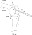
- FIG. 6A shows an isometric view of femur 12 and tibia 14 where a drilling operation is being performed, in accordance with at least one example of the present disclosure.
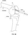
- FIG. 6B shows an isometric view of femur 12 and tibia 14 with intramedullary rod 604 installed, in accordance with at least one example of the present disclosure.
- FIGS. 6A and 6B are discussed below concurrently.
- Femur 12 and tibia 14 can be a femur and tibia, respectfully, of a human leg.
- Femur 12 can include condyles 16 and intramedullary cavity 18.
- Tibia 14 can include resected portion 20, which can be resected by operations performed prior to those operations described herein.
- drill bit 602 intramedullary (IM) rod 604, and orientation indicators Anterior, Posterior, Medial, and Lateral.
- Drill bit 602 can be a component engageable with a rotary device, such as a drill.
- the rotary device can rotate drill bit 602 at speeds sufficiently high to remove material (such as bone) in contact with drill bit 602. In this way, drill bit 602 can create a bore.
- Drill bit 602 can be comprised of metal alloys and other rigid materials (such as diamond) and combinations thereof.
- IM rod 604 can be a rigid member comprised of materials such as metals, plastics, and combinations thereof. IM rod 604 can be configured to be inserted into a bore created by drill bit 602. IM rod 604 can be further inserted into the bore and into intramedullary cavity 18 of femur 12.
- a drill or other rotary tool can be used to create a bore between condyles 16 of femur 12 to expose intramedullary cavity 18, as shown in FIG. 6A .
- IM rod 604 can be inserted into intramedullary cavity 18, as shown in FIG. 6B . Further operations are detailed in the figures below.
- FIG. 7A shows an isometric view of cutting guide assembly 100, in accordance with at least one example of the present disclosure.
- FIG. 7A shows arrow A and orientation indicators Anterior, Posterior, Medial, and Lateral.
- Cutting guide assembly 100 can be consistent with the above description of cutting guide assembly 100 in FIGS. 1-5 .
- FIG. 7A also shows inserts 104A and 104B, which can both be consistent with the description of insert 104 discussed above.
- Insert 104A can include angle ⁇ 1 and angle ⁇ 2 and insert 104B can include angle ⁇ 3 .
- Angle ⁇ 1 can represent a first valgus angle, or an angle between a mechanical axis and an anatomical axis of the femur.
- Angle ⁇ 2 can represent a second valgus angle and angle ⁇ 3 can represent a third valgus angle.
- angle ⁇ 1 and angle ⁇ 2 can be the same angle.
- angle ⁇ 1 and angle ⁇ 2 can be different angles.
- angle ⁇ 1 and angle ⁇ 2 can be different than angle ⁇ 3 .
- an insert with a desired valgus angle can be selected.
- the insert such as insert 104A
- the insert can then be inserted into channel 106 in the direction of arrow A, in some examples.
- insert 104A can be inserted into the posterior opening of channel 106 in a direction substantially opposite arrow A. That is, insert 104A can be inserted into channel 106 from either direction.
- cam 108 can be actuated, retracting actuator 110 (not shown in FIG. 7A ) out of channel 106, so that insert 104A can be placed as desired into channel 106. Once a location has been selected, cam 108 can be released, allowing actuator 110 to engage insert 104A. The rest of the operations are discussed with respect to the FIGS. below.
- FIG. 7B shows an isometric view of femur 12 and tibia 14 with cutting guide assembly 100 secured to the intramedullary rod 604, in accordance with at least one example of the present disclosure.
- Cutting guide assembly 100 can be consistent with the above description of cutting guide assembly 100.
- IM rod 604 can be guided through a central opening of base 102 and through an IM bore (such as bore 112 or 114) of insert 104 to secure cutting guide 100 to IM rod 604.
- IM bore such as bore 112 or 114
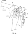
- FIG. 8A shows an isometric view of femur 12 and tibia 14 with cutting guide assembly 100 secured to the intramedullary rod 604 and anterior femoral feeler 802 secured to cutting guide assembly 100, in accordance with at least one example of the present disclosure.
- Cutting guide assembly 100 can be consistent with the above description of cutting guide assembly 100.
- Anterior femoral feeler 802 can be secured to cutting guide assembly and knob 804 can be adjusted to position the feeler relative to femur 12 and condyles 16.
- Cam 108 can be actuated to retracted actuator 110 (not shown in FIG. 8A ), allowing base 102 to translate in the anterior-posterior plane.
- base 102 can be translated anteriorly to reduce an amount of femur 12 that is to be resected from a distal portion of femur 12, whereby anterior femoral feeler 802 can provide an indication of the correct position based on contact between anterior femoral feeler 802 and/or its position relative to femur 12 and condyles 16 thereof.
- base 102 can be translated posteriorly to increase an amount of femur 12 that is to be resected from a distal portion of femur 12.
- cam 108 can be released, allowing the actuator to secure insert 104 to base 102.
- it can be determined that the relative position of insert 104 to base 102 is not desirable and the process of actuating cam 108, translating base 102, and releasing cam 108 can be repeated. In this way, cutting guide assembly 100 allows for a quick and easy selection (and reselection) of a position of base 102 to insert 104. This can increase procedural efficiency, saving time and cost.
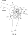
- FIG. 8B shows an isometric view of femur 12 and tibia 14 with a tibia rotation block and cutting guide assembly 100 secured to the intramedullary rod 604, in accordance with at least one example of the present disclosure.
- Cutting guide assembly 100 can be consistent with the above description of cutting guide assembly 100.
- ligament balancing can be achieved through rotation of cutting guide assembly 100 by securing tibia rotation block 806 to base 102 of cutting guide assembly 100.
- a desired external rotation of cutting guide assembly 100 of about 3° can be obtained automatically through correct balance and tension of the ligament system, in some examples.
- rotation can also be checked via the epicondylar axis using medial and lateral pins secured to base 102.
- FIG. 9B shows an isometric view of a femur and a tibia with pins 906 securing cutting guide assembly 100 to femur 12, in accordance with at least one example of the present disclosure.
- a drill can be used to drill into a distal portion of femur 12 through pin bores 142 to create a bore in a distal portion of femur 12.
- pins 906, which can be Steinmann pins in some examples, can be inserted through pin bores 142 and into bores of the bone to temporarily secure base 102 to femur 12.
- pins 906 can reduce rotation of base 102 and insert 104 relative to femur 12 and can reduce translation of base 102 and insert 104 along an axis of IM rod 604.
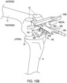
- posterior blade guide 1002 can be secured to a posterior portion of base 102.
- Posterior blade guide 1002 can include a blade slot sized to receive cutting tool 1004. The blade slot can limit movement of cutting tool 1004 to translation substantially perpendicular to the anterior-posterior plane, so that only a substantially planar cut of the posterior portion of femur 12 can be made with cutting tool 1004.
- FIG. 10B shows an isometric view of femur 12 and tibia 14 with cutting tool 1004 performing cut 22 of femur 12, in accordance with at least one example of the present disclosure.
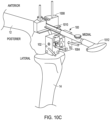
- FIG. 10C shows an isometric view of femur 12 and tibia 14 with secondary cutting guide 1008 secured to cutting guide assembly 100, in accordance with at least one example of the present disclosure.
- Secondary cutting guide 1008 can be a distal cutting guide configured to guide a cutting tool for making a distal femoral cut.
- outrigger 1010 can be securable to base 102. Outrigger 1010 can then be used to position distal cutting guide 1008 relative to base 102 and therefore relative to femur 12. Once distal cutting guide 1008 has been placed as desired and secured to femur 12, removal tool 1012 can be secured to base 102 and can be used to remove cutting guide assembly 100 and outrigger 1010from femur 12 so that a distal femoral cut can be performed using distal cutting guide 1008.
- FIG. 10 shows a flow chart using the devices and systems described above, in accordance with at least one example of this disclosure.
- the steps or operations of the method of FIG. 10 are illustrated in a particular order for convenience and clarity. Many of the discussed operations can be performed in a different sequence or in parallel, and some operations may be excluded, without materially impacting other operations.
- the method of FIG. 10 includes operations that may be performed by multiple different actors, devices, and/or systems. It is understood that subsets of the operations discussed in the method of FIG. 10 that are attributable to a single actor, device, or system could be considered a separate standalone process or method.
- method 1100 can begin with step 1102, where a femur (such as femur 12 of FIG. 6A ) can be bored or drilled using a tool (such as drill bit 602 of FIG. 6A ).
- a femur such as femur 12 of FIG. 6A
- a tool such as drill bit 602 of FIG. 6A
- cam 108 can be actuated to retract actuator 110 of cutting guide assembly 100, so that an angle guide (or insert 104) can be inserted into channel 106 of base 102 at step 1108 and also positioned relative to base 102.
- cam 108 can be released, allowing actuator 110 to secure the position of insert 104 relative to base 102 at step 1110.
- a bore of insert 104 (such as bore 112 or 114) and a central bore of base 102 can receive IM rod 604 therethrough.
- Cam 108 can then be actuated again at step 1114 to release the engagement between block 102 and insert 104.
- Base 102 can then be translated relative to insert 104 and IM rod 604 to position base 102 as desired relative to femur 12. Thereafter, cam 108 can be released to secure insert 104 relative to base 102.
- steps 1106 through 1118 can be repeated in any order to position base 102 and insert 104, as desired.
- cam 108 can be actuated to remove base 102 and insert 104 from IM rod 604.
Landscapes
- Health & Medical Sciences (AREA)
- Surgery (AREA)
- Life Sciences & Earth Sciences (AREA)
- Biomedical Technology (AREA)
- Public Health (AREA)
- Oral & Maxillofacial Surgery (AREA)
- Nuclear Medicine, Radiotherapy & Molecular Imaging (AREA)
- Veterinary Medicine (AREA)
- Dentistry (AREA)
- Engineering & Computer Science (AREA)
- Orthopedic Medicine & Surgery (AREA)
- Heart & Thoracic Surgery (AREA)
- Medical Informatics (AREA)
- Molecular Biology (AREA)
- Animal Behavior & Ethology (AREA)
- General Health & Medical Sciences (AREA)
- Physical Education & Sports Medicine (AREA)
- Transplantation (AREA)
- Surgical Instruments (AREA)
- Prostheses (AREA)
Claims (12)
- Verstellbare Schneidführung (100) zum Resezieren eines Knochens, wobei die Schneidführung Folgendes umfasst:
eine Basis (102), definierend:einen Kanal (106), der sich zwischen einem ersten Ende der Basis und einem zweiten Ende der Basis erstreckt; undeinen Schlitz (122), der den Kanal schneidet;einen Nocken (108), der mit der Basis verbunden und bedienbar ist, um sich innerhalb des Schlitzes zu bewegen;einen Aktor (110), der sich zumindest teilweise innerhalb des Schlitzes befindet, wobei der Aktor bedienbar ist, um sich durch Bewegung des Nockens zwischen einer ausgefahrenen Position und einer eingezogenen Position zu verschieben; undeinen Einsatz (104), der sich innerhalb des Kanals der Basis befindet, wobei der Einsatz relativ zu der Basis durch den Aktor gesichert ist, wenn der Aktor in der ausgefahrenen Position ist, und die Basis relativ zu dem Einsatz verschiebbar ist, wenn der Aktor in der eingezogenen Position ist, dadurch gekennzeichnet, dass der Einsatz eine erste intramedulläre Bohrung (114), die sich nahe einem anterioren Abschnitt des Einsatzes befindet, und eine zweite intramedulläre Bohrung (114), die sich nahe einem posterioren Abschnitt des Einsatzes befindet, beinhaltet. - Verstellbare Schneidführung nach Anspruch 1, wobei der Aktor zwischen der ausgefahrenen Position, wenn der Nocken in einer ersten Position ist, und der eingezogenen Position, wenn der Nocken in einer zweiten Position ist, bewegbar ist.
- Verstellbare Schneidführung nach einem der Ansprüche 1-2, wobei der Nocken schwenkbar an die Basis gekoppelt ist, um den Aktor in Eingriff zu nehmen.
- Verstellbare Schneidführung nach einem der Ansprüche 1 bis 3, wobei der Nocken bedienbar ist, um sich innerhalb des Schlitzes durch Drehung zu bewegen.
- Verstellbare Schneidführung nach einem vorhergehenden Anspruch, wobei der Einsatz eine Zahnstange (116) beinhaltet, die Zahnstangenzähne beinhaltet, und wobei der Aktor Aktorzähne (124) beinhaltet, die mit den Zahnstangenzähnen in Eingriff bringbar sind, um den Einsatz an der Basis zu sichern, wenn der Aktor in der ausgefahrenen Position ist.
- Verstellbare Schneidführung nach Anspruch 5, wobei der Kanal ferner eine Schiene (130) umfasst, wobei die Schiene konfiguriert ist, um die Zahnstange des Einsatzes aufzunehmen, wobei sich die Aktorzähne in die Schiene erstrecken, um die Zahnstangenzähne des Einsatzes in Eingriff zu nehmen, wenn der Aktor in der ausgefahrenen Position ist.
- Verstellbare Schneidführung nach einem der Ansprüche 1-6, ferner umfassend:
ein Vorspannelement (120), das mit dem Aktor und der Basis in Eingriff ist, um den Aktor in die ausgefahrene Position und den Nocken in die erste Position vorzuspannen. - Verstellbare Schneidführung nach einem der Ansprüche 1 bis 7, wobei der Aktor einen Schenkel (138) beinhaltet, der sich von dem Nocken weg in einen Verdrehsicherungsschlitz der Basis erstreckt, wobei der Schenkel in dem Verdrehsicherungsschlitz mit dem Aktor verschiebbar ist, wobei der Verdrehsicherungsschlitz mit dem Schenkel in Eingriff bringbar ist, um Drehung des Schenkels und des Aktors um eine Achse des Aktors zu begrenzen.
- Verstellbare Schneidführung nach Anspruch 8, wobei die Basis eine Vielzahl von Bohrungen (142) beinhaltet, die sich dort hindurch erstreckt, wobei die Vielzahl von Bohrungen im Wesentlichen parallel zu der ersten und der zweiten intramedullären Bohrung des Einsatzes ist.
- Verstellbare Schneidführung nach einem der Ansprüche 1-9, wobei der Kanal konfiguriert ist, um eine Vielzahl von Einsätzen, beinhaltend den Einsatz, anzunehmen, wobei jeder aus der Vielzahl von Einsätzen eine intramedulläre Stabbohrung beinhaltet, die einen Stabwinkel zwischen 1 Grad und 9 Grad aufweist.
- Verstellbare Schneidführung nach einem der Ansprüche 1-10, wobei die Schneidführung ein anteriorer/posteriorer Schneideblock zur Resektion eines distalen Abschnittes eines Femurs ist.
- Verstellbare Schneidführung nach Anspruch 11, wobei die Basis eine Vielzahl von Stiftöffnungen (142) beinhaltet, die sich durch die Basis erstreckt, wobei jede der Stiftöffnungen konfiguriert ist, um einen oder mehrere Stifte dort hindurch aufzunehmen, um die Basis an dem Knochen zu fixieren.
Applications Claiming Priority (3)
| Application Number | Priority Date | Filing Date | Title |
|---|---|---|---|
| US201762504759P | 2017-05-11 | 2017-05-11 | |
| EP18725159.0A EP3634262B1 (de) | 2017-05-11 | 2018-05-11 | Verstellbarer schneideblock für kniearthroplastie |
| PCT/EP2018/062208 WO2018206765A1 (en) | 2017-05-11 | 2018-05-11 | Adjustable cutting block for knee arthroplasty |
Related Parent Applications (1)
| Application Number | Title | Priority Date | Filing Date |
|---|---|---|---|
| EP18725159.0A Division EP3634262B1 (de) | 2017-05-11 | 2018-05-11 | Verstellbarer schneideblock für kniearthroplastie |
Publications (2)
| Publication Number | Publication Date |
|---|---|
| EP4035611A1 EP4035611A1 (de) | 2022-08-03 |
| EP4035611B1 true EP4035611B1 (de) | 2025-03-26 |
Family
ID=62186425
Family Applications (2)
| Application Number | Title | Priority Date | Filing Date |
|---|---|---|---|
| EP21179444.1A Active EP4035611B1 (de) | 2017-05-11 | 2018-05-11 | Verstellbarer schneideblock für kniearthroplastie |
| EP18725159.0A Active EP3634262B1 (de) | 2017-05-11 | 2018-05-11 | Verstellbarer schneideblock für kniearthroplastie |
Family Applications After (1)
| Application Number | Title | Priority Date | Filing Date |
|---|---|---|---|
| EP18725159.0A Active EP3634262B1 (de) | 2017-05-11 | 2018-05-11 | Verstellbarer schneideblock für kniearthroplastie |
Country Status (3)
| Country | Link |
|---|---|
| US (2) | US10905445B2 (de) |
| EP (2) | EP4035611B1 (de) |
| WO (1) | WO2018206765A1 (de) |
Families Citing this family (3)
| Publication number | Priority date | Publication date | Assignee | Title |
|---|---|---|---|---|
| US11172917B2 (en) * | 2015-01-09 | 2021-11-16 | Sterling Innovations, Llc | Devices and methods for establishing femoral and tibial resection positions in a total knee replacement procedure |
| US10905445B2 (en) | 2017-05-11 | 2021-02-02 | Zimmer Gmbh | Adjustable cutting block for knee arthroplasty |
| USD974558S1 (en) | 2020-12-18 | 2023-01-03 | Stryker European Operations Limited | Ultrasonic knife |
Family Cites Families (27)
| Publication number | Priority date | Publication date | Assignee | Title |
|---|---|---|---|---|
| US5486178A (en) | 1994-02-16 | 1996-01-23 | Hodge; W. Andrew | Femoral preparation instrumentation system and method |
| US5910143A (en) * | 1994-12-16 | 1999-06-08 | Exactech, Inc. | Intramedullary alignment guide tool |
| US5624444A (en) | 1995-02-10 | 1997-04-29 | Wixon; Richard | Femoral resection instrumentation including three-dimensional jig and method of use |
| US5776137A (en) | 1995-05-31 | 1998-07-07 | Katz; Lawrence | Method and apparatus for locating bone cuts at the distal condylar femur region to receive a knee prosthesis |
| US5662656A (en) | 1995-12-08 | 1997-09-02 | Wright Medical Technology, Inc. | Instrumentation and method for distal femoral sizing, and anterior and distal femoral resections |
| AU2054197A (en) | 1996-02-21 | 1997-09-10 | Smith & Nephew, Inc. | Posterior stabilized/constrained reamer guide |
| WO1998032384A1 (en) | 1997-01-28 | 1998-07-30 | New York Society For The Relief Of The Ruptured And Crippled Maintaining The Hospital For Special Surgery | Method and apparatus for femoral resection |
| US6013081A (en) | 1998-09-09 | 2000-01-11 | Sulzer Orthopedics Inc. | Apparatus and method for anterior and posterior referenced sizing and distal femur resection |
| US7635390B1 (en) * | 2000-01-14 | 2009-12-22 | Marctec, Llc | Joint replacement component having a modular articulating surface |
| US7104996B2 (en) | 2000-01-14 | 2006-09-12 | Marctec. Llc | Method of performing surgery |
| KR100528121B1 (ko) * | 2003-03-27 | 2005-11-15 | 김종범 | 인공슬관절 사이즈 결정장치 |
| WO2006010871A1 (en) | 2004-07-27 | 2006-02-02 | Biomet Merck Limited | Bone jig |
| US7618420B2 (en) * | 2005-02-17 | 2009-11-17 | Howmedica Osteonics Corp. | Locking intramedullary jig |
| US7621920B2 (en) | 2005-06-13 | 2009-11-24 | Zimmer, Inc. | Adjustable cut guide |
| US8702714B2 (en) | 2006-03-09 | 2014-04-22 | Microsoft Orthopedics Holdings Inc. | Instruments for total knee arthroplasty |
| US7686812B2 (en) * | 2006-06-30 | 2010-03-30 | Howmedica Osteonics Corp. | Method for setting the rotational position of a femoral component |
| US8187280B2 (en) | 2007-10-10 | 2012-05-29 | Biomet Manufacturing Corp. | Knee joint prosthesis system and method for implantation |
| US8814874B2 (en) | 2007-02-13 | 2014-08-26 | Medtronic Navigation, Inc. | Navigated cut guide for total knee reconstruction |
| US8372080B2 (en) | 2008-08-26 | 2013-02-12 | Zimmer, Inc. | Trans-cut slot adjustment mechanism |
| US8313491B2 (en) | 2009-08-20 | 2012-11-20 | Wright Medical Technology, Inc. | Adjustable femoral resection guide |
| EP2490605A4 (de) | 2009-10-23 | 2014-07-16 | Synvasive Technology Inc | Kniebalancierung für revisionschirurgie |
| US9204897B2 (en) | 2011-12-19 | 2015-12-08 | Zimmer, Inc. | Surgical cutting guide |
| US9795392B2 (en) * | 2012-02-06 | 2017-10-24 | Arthrex, Inc. | Surgical instrumentation set and surgical technique |
| US9050107B2 (en) | 2012-05-30 | 2015-06-09 | Depuy (Ireland) | Method of surgically preparing a patient's femur |
| US9636122B2 (en) * | 2013-03-15 | 2017-05-02 | Depuy Ireland Unlimited Company | Femoral orthopaedic instrument assembly for setting offset |
| US9113918B2 (en) | 2013-03-15 | 2015-08-25 | Depuy (Ireland) | Femoral surgical instrument and method of using same |
| US10905445B2 (en) | 2017-05-11 | 2021-02-02 | Zimmer Gmbh | Adjustable cutting block for knee arthroplasty |
-
2018
- 2018-04-23 US US15/959,845 patent/US10905445B2/en active Active
- 2018-05-11 EP EP21179444.1A patent/EP4035611B1/de active Active
- 2018-05-11 WO PCT/EP2018/062208 patent/WO2018206765A1/en not_active Ceased
- 2018-05-11 EP EP18725159.0A patent/EP3634262B1/de active Active
-
2020
- 2020-12-23 US US17/132,180 patent/US11484326B2/en active Active
Also Published As
| Publication number | Publication date |
|---|---|
| US20180325530A1 (en) | 2018-11-15 |
| US11484326B2 (en) | 2022-11-01 |
| WO2018206765A1 (en) | 2018-11-15 |
| US10905445B2 (en) | 2021-02-02 |
| EP3634262B1 (de) | 2021-06-16 |
| US20210177440A1 (en) | 2021-06-17 |
| EP3634262A1 (de) | 2020-04-15 |
| EP4035611A1 (de) | 2022-08-03 |
Similar Documents
| Publication | Publication Date | Title |
|---|---|---|
| JP7400045B2 (ja) | 整形外科的関節置換手技における患者の大腿骨を準備するためのシステム及び方法 | |
| US8118811B2 (en) | Apparatus for knee surgery and method of use | |
| US8062377B2 (en) | Methods and apparatus for knee arthroplasty | |
| US8298238B2 (en) | Methods and apparatus for pivotable guide surfaces for arthroplasty | |
| EP2623045B1 (de) | Operationsinstrumentensatz | |
| US10413307B2 (en) | Femoral orthopaedic instrument assembly for setting offset | |
| US6056754A (en) | Method and apparatus for patella resection and guide handle | |
| US6645215B1 (en) | Tibial rotation guide | |
| US9603723B2 (en) | Femoral orthopaedic surgical instrument including a measurement device and method of use of same | |
| US9232950B2 (en) | Femoral orthopaedic surgical instruments for setting offset | |
| US9282981B2 (en) | Method of surgically preparing a patients femur | |
| AU2016289953A1 (en) | Femoral finishing guide | |
| US11484326B2 (en) | Adjustable cutting block for knee arthroplasty | |
| US20140171954A1 (en) | Method and apparatus for performing knee arthroplasty | |
| US20180008424A1 (en) | Hinge knee preparation instrumentation and associated methods | |
| WO2003013373A1 (en) | Guide for locating femur resection plane | |
| JP5991549B2 (ja) | 回転切削装置 | |
| US10646237B2 (en) | Associated instruments and methods for posterior stabilized knee preparation | |
| AU2002319511B2 (en) | Guide for locating femur resection plane | |
| AU2002319511A1 (en) | Guide for locating femur resection plane |
Legal Events
| Date | Code | Title | Description |
|---|---|---|---|
| PUAI | Public reference made under article 153(3) epc to a published international application that has entered the european phase |
Free format text: ORIGINAL CODE: 0009012 |
|
| STAA | Information on the status of an ep patent application or granted ep patent |
Free format text: STATUS: THE APPLICATION HAS BEEN PUBLISHED |
|
| AC | Divisional application: reference to earlier application |
Ref document number: 3634262 Country of ref document: EP Kind code of ref document: P |
|
| AK | Designated contracting states |
Kind code of ref document: A1 Designated state(s): AL AT BE BG CH CY CZ DE DK EE ES FI FR GB GR HR HU IE IS IT LI LT LU LV MC MK MT NL NO PL PT RO RS SE SI SK SM TR |
|
| STAA | Information on the status of an ep patent application or granted ep patent |
Free format text: STATUS: REQUEST FOR EXAMINATION WAS MADE |
|
| 17P | Request for examination filed |
Effective date: 20230202 |
|
| RBV | Designated contracting states (corrected) |
Designated state(s): AL AT BE BG CH CY CZ DE DK EE ES FI FR GB GR HR HU IE IS IT LI LT LU LV MC MK MT NL NO PL PT RO RS SE SI SK SM TR |
|
| STAA | Information on the status of an ep patent application or granted ep patent |
Free format text: STATUS: EXAMINATION IS IN PROGRESS |
|
| 17Q | First examination report despatched |
Effective date: 20231129 |
|
| GRAP | Despatch of communication of intention to grant a patent |
Free format text: ORIGINAL CODE: EPIDOSNIGR1 |
|
| STAA | Information on the status of an ep patent application or granted ep patent |
Free format text: STATUS: GRANT OF PATENT IS INTENDED |
|
| INTG | Intention to grant announced |
Effective date: 20241018 |
|
| GRAS | Grant fee paid |
Free format text: ORIGINAL CODE: EPIDOSNIGR3 |
|
| GRAA | (expected) grant |
Free format text: ORIGINAL CODE: 0009210 |
|
| STAA | Information on the status of an ep patent application or granted ep patent |
Free format text: STATUS: THE PATENT HAS BEEN GRANTED |
|
| AC | Divisional application: reference to earlier application |
Ref document number: 3634262 Country of ref document: EP Kind code of ref document: P |
|
| AK | Designated contracting states |
Kind code of ref document: B1 Designated state(s): AL AT BE BG CH CY CZ DE DK EE ES FI FR GB GR HR HU IE IS IT LI LT LU LV MC MK MT NL NO PL PT RO RS SE SI SK SM TR |
|
| REG | Reference to a national code |
Ref country code: GB Ref legal event code: FG4D |
|
| REG | Reference to a national code |
Ref country code: CH Ref legal event code: EP |
|
| P01 | Opt-out of the competence of the unified patent court (upc) registered |
Free format text: CASE NUMBER: APP_8583/2025 Effective date: 20250220 |
|
| REG | Reference to a national code |
Ref country code: DE Ref legal event code: R096 Ref document number: 602018080616 Country of ref document: DE |
|
| REG | Reference to a national code |
Ref country code: IE Ref legal event code: FG4D |
|
| PGFP | Annual fee paid to national office [announced via postgrant information from national office to epo] |
Ref country code: GB Payment date: 20250327 Year of fee payment: 8 |
|
| PG25 | Lapsed in a contracting state [announced via postgrant information from national office to epo] |
Ref country code: RS Free format text: LAPSE BECAUSE OF FAILURE TO SUBMIT A TRANSLATION OF THE DESCRIPTION OR TO PAY THE FEE WITHIN THE PRESCRIBED TIME-LIMIT Effective date: 20250626 |
|
| PG25 | Lapsed in a contracting state [announced via postgrant information from national office to epo] |
Ref country code: FI Free format text: LAPSE BECAUSE OF FAILURE TO SUBMIT A TRANSLATION OF THE DESCRIPTION OR TO PAY THE FEE WITHIN THE PRESCRIBED TIME-LIMIT Effective date: 20250326 |
|
| PGFP | Annual fee paid to national office [announced via postgrant information from national office to epo] |
Ref country code: DE Payment date: 20250521 Year of fee payment: 8 |
|
| REG | Reference to a national code |
Ref country code: LT Ref legal event code: MG9D |
|
| PG25 | Lapsed in a contracting state [announced via postgrant information from national office to epo] |
Ref country code: NO Free format text: LAPSE BECAUSE OF FAILURE TO SUBMIT A TRANSLATION OF THE DESCRIPTION OR TO PAY THE FEE WITHIN THE PRESCRIBED TIME-LIMIT Effective date: 20250626 |
|
| PG25 | Lapsed in a contracting state [announced via postgrant information from national office to epo] |
Ref country code: HR Free format text: LAPSE BECAUSE OF FAILURE TO SUBMIT A TRANSLATION OF THE DESCRIPTION OR TO PAY THE FEE WITHIN THE PRESCRIBED TIME-LIMIT Effective date: 20250326 |
|
| PG25 | Lapsed in a contracting state [announced via postgrant information from national office to epo] |
Ref country code: LV Free format text: LAPSE BECAUSE OF FAILURE TO SUBMIT A TRANSLATION OF THE DESCRIPTION OR TO PAY THE FEE WITHIN THE PRESCRIBED TIME-LIMIT Effective date: 20250326 |
|
| PGFP | Annual fee paid to national office [announced via postgrant information from national office to epo] |
Ref country code: FR Payment date: 20250528 Year of fee payment: 8 |
|
| PG25 | Lapsed in a contracting state [announced via postgrant information from national office to epo] |
Ref country code: BG Free format text: LAPSE BECAUSE OF FAILURE TO SUBMIT A TRANSLATION OF THE DESCRIPTION OR TO PAY THE FEE WITHIN THE PRESCRIBED TIME-LIMIT Effective date: 20250326 Ref country code: GR Free format text: LAPSE BECAUSE OF FAILURE TO SUBMIT A TRANSLATION OF THE DESCRIPTION OR TO PAY THE FEE WITHIN THE PRESCRIBED TIME-LIMIT Effective date: 20250627 |
|
| PGFP | Annual fee paid to national office [announced via postgrant information from national office to epo] |
Ref country code: CH Payment date: 20250601 Year of fee payment: 8 |
|
| REG | Reference to a national code |
Ref country code: NL Ref legal event code: MP Effective date: 20250326 |
|
| PG25 | Lapsed in a contracting state [announced via postgrant information from national office to epo] |
Ref country code: NL Free format text: LAPSE BECAUSE OF FAILURE TO SUBMIT A TRANSLATION OF THE DESCRIPTION OR TO PAY THE FEE WITHIN THE PRESCRIBED TIME-LIMIT Effective date: 20250326 |
|
| PG25 | Lapsed in a contracting state [announced via postgrant information from national office to epo] |
Ref country code: SE Free format text: LAPSE BECAUSE OF FAILURE TO SUBMIT A TRANSLATION OF THE DESCRIPTION OR TO PAY THE FEE WITHIN THE PRESCRIBED TIME-LIMIT Effective date: 20250326 |
|
| REG | Reference to a national code |
Ref country code: AT Ref legal event code: MK05 Ref document number: 1778253 Country of ref document: AT Kind code of ref document: T Effective date: 20250326 |
|
| PG25 | Lapsed in a contracting state [announced via postgrant information from national office to epo] |
Ref country code: SM Free format text: LAPSE BECAUSE OF FAILURE TO SUBMIT A TRANSLATION OF THE DESCRIPTION OR TO PAY THE FEE WITHIN THE PRESCRIBED TIME-LIMIT Effective date: 20250326 |
|
| PG25 | Lapsed in a contracting state [announced via postgrant information from national office to epo] |
Ref country code: PT Free format text: LAPSE BECAUSE OF FAILURE TO SUBMIT A TRANSLATION OF THE DESCRIPTION OR TO PAY THE FEE WITHIN THE PRESCRIBED TIME-LIMIT Effective date: 20250728 Ref country code: ES Free format text: LAPSE BECAUSE OF FAILURE TO SUBMIT A TRANSLATION OF THE DESCRIPTION OR TO PAY THE FEE WITHIN THE PRESCRIBED TIME-LIMIT Effective date: 20250326 |
|
| PG25 | Lapsed in a contracting state [announced via postgrant information from national office to epo] |
Ref country code: PL Free format text: LAPSE BECAUSE OF FAILURE TO SUBMIT A TRANSLATION OF THE DESCRIPTION OR TO PAY THE FEE WITHIN THE PRESCRIBED TIME-LIMIT Effective date: 20250326 |
|
| PGFP | Annual fee paid to national office [announced via postgrant information from national office to epo] |
Ref country code: IT Payment date: 20250627 Year of fee payment: 8 |
|
| PG25 | Lapsed in a contracting state [announced via postgrant information from national office to epo] |
Ref country code: AT Free format text: LAPSE BECAUSE OF FAILURE TO SUBMIT A TRANSLATION OF THE DESCRIPTION OR TO PAY THE FEE WITHIN THE PRESCRIBED TIME-LIMIT Effective date: 20250326 |
|
| PG25 | Lapsed in a contracting state [announced via postgrant information from national office to epo] |
Ref country code: EE Free format text: LAPSE BECAUSE OF FAILURE TO SUBMIT A TRANSLATION OF THE DESCRIPTION OR TO PAY THE FEE WITHIN THE PRESCRIBED TIME-LIMIT Effective date: 20250326 |
|
| PG25 | Lapsed in a contracting state [announced via postgrant information from national office to epo] |
Ref country code: RO Free format text: LAPSE BECAUSE OF FAILURE TO SUBMIT A TRANSLATION OF THE DESCRIPTION OR TO PAY THE FEE WITHIN THE PRESCRIBED TIME-LIMIT Effective date: 20250326 |
|
| PG25 | Lapsed in a contracting state [announced via postgrant information from national office to epo] |
Ref country code: SK Free format text: LAPSE BECAUSE OF FAILURE TO SUBMIT A TRANSLATION OF THE DESCRIPTION OR TO PAY THE FEE WITHIN THE PRESCRIBED TIME-LIMIT Effective date: 20250326 |
|
| PG25 | Lapsed in a contracting state [announced via postgrant information from national office to epo] |
Ref country code: IS Free format text: LAPSE BECAUSE OF FAILURE TO SUBMIT A TRANSLATION OF THE DESCRIPTION OR TO PAY THE FEE WITHIN THE PRESCRIBED TIME-LIMIT Effective date: 20250726 |
|
| REG | Reference to a national code |
Ref country code: DE Ref legal event code: R097 Ref document number: 602018080616 Country of ref document: DE |
|
| PG25 | Lapsed in a contracting state [announced via postgrant information from national office to epo] |
Ref country code: DK Free format text: LAPSE BECAUSE OF FAILURE TO SUBMIT A TRANSLATION OF THE DESCRIPTION OR TO PAY THE FEE WITHIN THE PRESCRIBED TIME-LIMIT Effective date: 20250326 |
|
| PG25 | Lapsed in a contracting state [announced via postgrant information from national office to epo] |
Ref country code: LU Free format text: LAPSE BECAUSE OF NON-PAYMENT OF DUE FEES Effective date: 20250511 |
|
| PG25 | Lapsed in a contracting state [announced via postgrant information from national office to epo] |
Ref country code: CZ Free format text: LAPSE BECAUSE OF FAILURE TO SUBMIT A TRANSLATION OF THE DESCRIPTION OR TO PAY THE FEE WITHIN THE PRESCRIBED TIME-LIMIT Effective date: 20250326 |
|
| REG | Reference to a national code |
Ref country code: BE Ref legal event code: MM Effective date: 20250531 |
|
| PG25 | Lapsed in a contracting state [announced via postgrant information from national office to epo] |
Ref country code: MC Free format text: LAPSE BECAUSE OF FAILURE TO SUBMIT A TRANSLATION OF THE DESCRIPTION OR TO PAY THE FEE WITHIN THE PRESCRIBED TIME-LIMIT Effective date: 20250326 |
|
| PLBE | No opposition filed within time limit |
Free format text: ORIGINAL CODE: 0009261 |
|
| STAA | Information on the status of an ep patent application or granted ep patent |
Free format text: STATUS: NO OPPOSITION FILED WITHIN TIME LIMIT |
|
| REG | Reference to a national code |
Ref country code: CH Ref legal event code: L10 Free format text: ST27 STATUS EVENT CODE: U-0-0-L10-L00 (AS PROVIDED BY THE NATIONAL OFFICE) Effective date: 20260211 |
|
| 26N | No opposition filed |
Effective date: 20260105 |
|
| PG25 | Lapsed in a contracting state [announced via postgrant information from national office to epo] |
Ref country code: IE Free format text: LAPSE BECAUSE OF NON-PAYMENT OF DUE FEES Effective date: 20250511 |
|
| PG25 | Lapsed in a contracting state [announced via postgrant information from national office to epo] |
Ref country code: BE Free format text: LAPSE BECAUSE OF NON-PAYMENT OF DUE FEES Effective date: 20250531 |