EP4034841B1 - Verfahren und system zur fahrzeugfahrunterstützung - Google Patents
Verfahren und system zur fahrzeugfahrunterstützung Download PDFInfo
- Publication number
- EP4034841B1 EP4034841B1 EP20800987.8A EP20800987A EP4034841B1 EP 4034841 B1 EP4034841 B1 EP 4034841B1 EP 20800987 A EP20800987 A EP 20800987A EP 4034841 B1 EP4034841 B1 EP 4034841B1
- Authority
- EP
- European Patent Office
- Prior art keywords
- hmd
- vehicle
- boresighting
- reference element
- respect
- Prior art date
- Legal status (The legal status is an assumption and is not a legal conclusion. Google has not performed a legal analysis and makes no representation as to the accuracy of the status listed.)
- Active
Links
Images


Classifications
-
- G—PHYSICS
- G02—OPTICS
- G02B—OPTICAL ELEMENTS, SYSTEMS OR APPARATUS
- G02B27/00—Optical systems or apparatus not provided for by any of the groups G02B1/00 - G02B26/00, G02B30/00
- G02B27/01—Head-up displays
- G02B27/0101—Head-up displays characterised by optical features
-
- G—PHYSICS
- G01—MEASURING; TESTING
- G01C—MEASURING DISTANCES, LEVELS OR BEARINGS; SURVEYING; NAVIGATION; GYROSCOPIC INSTRUMENTS; PHOTOGRAMMETRY OR VIDEOGRAMMETRY
- G01C21/00—Navigation; Navigational instruments not provided for in groups G01C1/00 - G01C19/00
- G01C21/005—Navigation; Navigational instruments not provided for in groups G01C1/00 - G01C19/00 with correlation of navigation data from several sources, e.g. map or contour matching
-
- G—PHYSICS
- G01—MEASURING; TESTING
- G01C—MEASURING DISTANCES, LEVELS OR BEARINGS; SURVEYING; NAVIGATION; GYROSCOPIC INSTRUMENTS; PHOTOGRAMMETRY OR VIDEOGRAMMETRY
- G01C21/00—Navigation; Navigational instruments not provided for in groups G01C1/00 - G01C19/00
- G01C21/26—Navigation; Navigational instruments not provided for in groups G01C1/00 - G01C19/00 specially adapted for navigation in a road network
- G01C21/34—Route searching; Route guidance
- G01C21/36—Input/output arrangements for on-board computers
- G01C21/3602—Input other than that of destination using image analysis, e.g. detection of road signs, lanes, buildings, real preceding vehicles using a camera
-
- G—PHYSICS
- G01—MEASURING; TESTING
- G01C—MEASURING DISTANCES, LEVELS OR BEARINGS; SURVEYING; NAVIGATION; GYROSCOPIC INSTRUMENTS; PHOTOGRAMMETRY OR VIDEOGRAMMETRY
- G01C21/00—Navigation; Navigational instruments not provided for in groups G01C1/00 - G01C19/00
- G01C21/26—Navigation; Navigational instruments not provided for in groups G01C1/00 - G01C19/00 specially adapted for navigation in a road network
- G01C21/34—Route searching; Route guidance
- G01C21/36—Input/output arrangements for on-board computers
- G01C21/3626—Details of the output of route guidance instructions
- G01C21/365—Guidance using head up displays or projectors, e.g. virtual vehicles or arrows projected on the windscreen or on the road itself
-
- G—PHYSICS
- G02—OPTICS
- G02B—OPTICAL ELEMENTS, SYSTEMS OR APPARATUS
- G02B27/00—Optical systems or apparatus not provided for by any of the groups G02B1/00 - G02B26/00, G02B30/00
- G02B27/0093—Optical systems or apparatus not provided for by any of the groups G02B1/00 - G02B26/00, G02B30/00 with means for monitoring data relating to the user, e.g. head-tracking, eye-tracking
-
- G—PHYSICS
- G02—OPTICS
- G02B—OPTICAL ELEMENTS, SYSTEMS OR APPARATUS
- G02B27/00—Optical systems or apparatus not provided for by any of the groups G02B1/00 - G02B26/00, G02B30/00
- G02B27/01—Head-up displays
- G02B27/017—Head mounted
- G02B27/0172—Head mounted characterised by optical features
-
- G—PHYSICS
- G06—COMPUTING OR CALCULATING; COUNTING
- G06F—ELECTRIC DIGITAL DATA PROCESSING
- G06F3/00—Input arrangements for transferring data to be processed into a form capable of being handled by the computer; Output arrangements for transferring data from processing unit to output unit, e.g. interface arrangements
- G06F3/01—Input arrangements or combined input and output arrangements for interaction between user and computer
- G06F3/011—Arrangements for interaction with the human body, e.g. for user immersion in virtual reality
- G06F3/012—Head tracking input arrangements
-
- G—PHYSICS
- G06—COMPUTING OR CALCULATING; COUNTING
- G06T—IMAGE DATA PROCESSING OR GENERATION, IN GENERAL
- G06T3/00—Geometric image transformations in the plane of the image
- G06T3/20—Linear translation of whole images or parts thereof, e.g. panning
-
- G—PHYSICS
- G06—COMPUTING OR CALCULATING; COUNTING
- G06T—IMAGE DATA PROCESSING OR GENERATION, IN GENERAL
- G06T3/00—Geometric image transformations in the plane of the image
- G06T3/60—Rotation of whole images or parts thereof
-
- G—PHYSICS
- G06—COMPUTING OR CALCULATING; COUNTING
- G06T—IMAGE DATA PROCESSING OR GENERATION, IN GENERAL
- G06T7/00—Image analysis
- G06T7/70—Determining position or orientation of objects or cameras
-
- G—PHYSICS
- G02—OPTICS
- G02B—OPTICAL ELEMENTS, SYSTEMS OR APPARATUS
- G02B27/00—Optical systems or apparatus not provided for by any of the groups G02B1/00 - G02B26/00, G02B30/00
- G02B27/01—Head-up displays
- G02B27/0101—Head-up displays characterised by optical features
- G02B2027/0138—Head-up displays characterised by optical features comprising image capture systems, e.g. camera
-
- G—PHYSICS
- G02—OPTICS
- G02B—OPTICAL ELEMENTS, SYSTEMS OR APPARATUS
- G02B27/00—Optical systems or apparatus not provided for by any of the groups G02B1/00 - G02B26/00, G02B30/00
- G02B27/01—Head-up displays
- G02B27/0101—Head-up displays characterised by optical features
- G02B2027/014—Head-up displays characterised by optical features comprising information/image processing systems
-
- G—PHYSICS
- G06—COMPUTING OR CALCULATING; COUNTING
- G06T—IMAGE DATA PROCESSING OR GENERATION, IN GENERAL
- G06T2207/00—Indexing scheme for image analysis or image enhancement
- G06T2207/30—Subject of image; Context of image processing
- G06T2207/30244—Camera pose
-
- G—PHYSICS
- G06—COMPUTING OR CALCULATING; COUNTING
- G06T—IMAGE DATA PROCESSING OR GENERATION, IN GENERAL
- G06T2207/00—Indexing scheme for image analysis or image enhancement
- G06T2207/30—Subject of image; Context of image processing
- G06T2207/30248—Vehicle exterior or interior
- G06T2207/30268—Vehicle interior
Definitions
- the present invention relates to the field of transport vehicles.
- the invention relates to a method and a system for assisting the driving of a vehicle.
- driving information such as information on movement speed, fuel level, navigation directions or the like, is shown in the dashboard of a vehicle or on any infotainment screens with which the vehicle is equipped. Both the dashboard and the screens are often located in the vehicle in positions which require the driver to at least partially take his eyes off the road environment, thus reducing both driving safety and the possibility of using such information.
- HUD Head Up Displays', or HUD for short, have been proposed as a partial solution to this problem.
- An HUD is a system which allows to project images onto the windscreen of a vehicle.
- HUDs allow information to be projected directly onto the car's windscreen, allowing the driver to stay focused on driving, always keeping his gaze on the road.
- HUD 1.0 the current standard of HUDs, known as HUD 1.0, is only used to show redundant information provided by classic on-board instrumentation. Furthermore, the Applicant has observed that the HUD technology does not allow to effectively depict elements of augmented reality. In fact, the extension required by the projection system for a complete coverage of the driver's field of vision is much greater than that technologically available at the current state of the art. In particular, there are no HUDs capable of exploiting the entire main field of vision substantially defined by the vehicle's windscreen, as well as a secondary field of vision, such as one or more side windows.
- HUD Head Mounted Displays
- HMD 'Head Mounted Displays', which comprise a transparent or semi-transparent screen on which images can be reproduced, for example to provide driving assistance information to a user wearing the HMD while driving the vehicle.
- U.S. patent application no. US 2016/084661 describes a system and method which act as a driving tool and provide feedback to a driver, such as real-time visual feedback offered via an augmented reality device.
- the guidance system collects vehicle-related information and driver information - for example, the direction of the driver's gaze determined by an HMD - and uses this input information to generate real-time visual feedback in the form of virtual guidelines and other driving recommendations.
- These driving recommendations can be presented to the driver via an augmented reality device, such as an HUD display, where virtual guidance lines are projected onto the vehicle's windscreen so as to be superimposed on the actual road surface seen by the driver and can show the driver a line or route to follow.
- other driving recommendations can be given, such as braking, accelerating, steering and shifting suggestions.
- European patent no. EP 2933707 describes a method for dynamically orienting what is presented by an HMD.
- the described method includes using at least one sensor installed on an HMD worn by the driver of a vehicle, to collect HMD movement data, and to use at least one sensor, mounted on the vehicle, to collect the vehicle movement data.
- the method therefore involves performing an analysis of the movement data of the HMD and the vehicle movement data to detect any differences therebetween. Based on the differences found, an orientation of the HMD device relative to the vehicle is calculated, calculated as regular data to be presented on a screen of the HMD device based on the newly calculated orientation.
- the method proposed in EP 2933707 is able to determine the orientation of the HMD, it does not allow satisfactory accuracy and precision to be obtained. Furthermore, the method requires high computational resources to calculate and generate data from consistently presented HMD data based on the comparison of images of a scenario visible to the driver through a vehicle windscreen.
- An object of the present invention is to overcome the disadvantages of the prior art.
- an object of the present invention is to present a method and system for feedback offered via an augmented reality device.
- the guidance system collects vehicle-related information and driver information - for example, the direction of the driver's gaze determined by an HMD - and uses this input information to generate real-time visual feedback in the form of virtual guidelines and other driving recommendations.
- These driving recommendations can be presented to the driver via an augmented reality device, such as an HUD display, where virtual guidance lines are projected onto the vehicle's windscreen so as to be superimposed on the actual road surface seen by the driver and can show the driver a line or route to follow.
- other driving recommendations can be given, such as braking, accelerating, steering and shifting suggestions.
- European patent no. EP 2933707 describes a method for dynamically orienting what is presented by an HMD.
- the described method includes using at least one sensor installed on an HMD worn by the driver of a vehicle, to collect HMD movement data, and to use at least one sensor, mounted on the vehicle, to collect the vehicle movement data.
- the method therefore involves performing an analysis of the movement data of the HMD and the vehicle movement data to detect any differences therebetween. Based on the differences found, an orientation of the HMD device relative to the vehicle is calculated, calculated as regular data to be presented on a screen of the HMD device based on the newly calculated orientation.
- the method proposed in EP 2933707 is able to determine the orientation of the HMD, it does not allow satisfactory accuracy and precision to be obtained. Furthermore, the method requires high computational resources to calculate and generate data from consistently presented HMD data based on the comparison of images of a scenario visible to the driver through a vehicle windscreen.
- An object of the present invention is to overcome the disadvantages of the prior art.
- an object of the present invention is to present a method and system for assisting driving capable of providing precise and reliable indications which assist a user while driving a vehicle.
- An object of the present invention is to present a method and a system for reproducing elements of augmented reality adapted to improve the driving experience of a user while using the vehicle.
- the invention is set out by the method according to claim 1.
- the visualization position is such that a user wearing the screen sees the image in correspondence of the object of interest.
- the method according to the present invention needs to acquire and process only positioning information such as that provided by a global navigation system or GNSS (for example, GPS, Galileo, GLONASS, Beidou, etc.), but does not require processing acquired images to recognize objects visible through the vehicle windscreen in order to correctly display the augmented reality images.
- GNSS global navigation system
- This allows to operate in real time with a high accuracy and precision in the display of augmented reality images with substantially lower computational cost and hardware requirements.
- the invention is set out as in the system according to claim 9.
- the HMD comprises at least two cameras arranged on opposite sides of a screen of the HMD.
- the step of determining a relative position of the HMD with respect to the reference element involves:
- the system comprises a plurality of reference elements of which one selected reference element acts as the main reference element and the other reference elements act as secondary reference elements.
- the method further comprises the step where for each secondary reference element, calculating a reference relationship corresponding to a rototranslation relationship between the secondary reference element with respect to the main reference element.
- the step of determining a relative position of the HMD with respect to the reference element includes:
- the step of determining a view volume involves:
- the position and orientation of the HMD relative to the reference element are determined contextually, i.e., the pose of the HMD relative to the reference element is determined. Therefore, analysis steps of two images acquired by two cameras and/or the use of several reference elements as described above in relation to the position of the HMD can also be envisaged, also to determine the orientation of the HMD, obtaining the same benefits.
- the solutions described above allow to determine the pose of the HMD with precision even while the vehicle is in motion.
- the pose of the HMD is determined in a more reliable manner and does not require the implementation of complex hardware and/or software components, as opposed to known solutions which involve the use of IMUs and other sensors to calculate the position and orientation of the HMD, moreover, with limited accuracy when the vehicle is in motion.
- the method further comprises the steps of:
- this measurement of the discrepancy comprises defining a rototranslation relationship between a virtual boresighting position and the boresighting position, said virtual boresighting position corresponding to the projection of the visualization position in a three-dimensional reference system.
- the compensation law is determined on the basis of said rototranslation relationship.
- the method provides that a boresighting object is situated in the boresighting position.
- defining a rototranslation relationship preferably involves:
- the method further comprises the step of:
- a different aspect concerns a system for assisting the driving of a vehicle.
- such a system comprises:
- This system is particularly compact and allows information to be provided to the user driving the vehicle in a precise and reliable way using limited hardware resources.
- the at least one reference element is backlit so as to be more simply identifiable.
- the system comprises a plurality of reference elements each comprising a respective identification code, so as to allow to distinguish the reference elements from each other.
- the positioning module comprises a GNSS module. Additionally or alternatively, the positioning module may comprise a triangulation module of electromagnetic signals, a radar, a lidar and/or similar devices.
- the processing unit stores or is connectable to a positioning data database, to acquire at least one position of interest associated with a corresponding object of interest.
- the processing unit is operatively connected to at least one of:
- the system is able to acquire and display a considerable amount of useful information to assist the driving of the vehicle.
- a system 1 comprises a wearable screen, more commonly indicated as Head Mount Display, or HMD 10, a positioning module, for example a GNSS module 20 (Global Navigation Satellite System), a processing unit 30 configured to connect to the GNSS module 20 and to the HMD 10, and one or more markers 40 of the ArUco type in the example considered.
- HMD Head Mount Display
- GNSS module 20 Global Navigation Satellite System
- processing unit 30 configured to connect to the GNSS module 20 and to the HMD 10
- markers 40 of the ArUco type in the example considered.
- the GNSS module 20 is configured to provide periodically and/or upon request an indication on a detected position, preferably, defined in a three-dimensional reference system originating in the centre of the Earth - referred to below with the term 'global reference system'.
- the GNSS module 20 comprises a GPS navigator and is configured to provide a set of geographical coordinates indicative of a global position detected by the GNSS module 20 and therefore of the vehicle 5.
- the HMD 10 comprises a transparent and/or semi-transparent screen 11, such as to allow a user wearing the HMD 10 to see through the screen 11 (as schematically illustrated in Figures 5a and 6 ). Furthermore, the HMD 10 is configured - for example, it comprises suitable circuitry (not shown) - to display images on the screen 11 which are superimposed on what is present in the field of view (FOV) of a user wearing the HMD 10 - referred to below as 'field of view FOV of the HMD 10' for the sake of brevity (schematically illustrated in Figure 2 ) -, thus creating an augmented reality effect.
- the HMD 10 may comprise a local processing unit 13 configured to generate the images to be displayed on the basis of data and/or instructions provided by the processing unit 30.
- the HMD 10 comprises a pair of cameras 15 configured to frame the same region of space from different points of view (as schematically illustrated in Figures 5a-5c ).
- the cameras 15 of the HMD 10 are arranged on opposite sides of a frame of the screen 11 of the HMD.
- Each of the cameras 15 is configured to acquire one or more images substantially corresponding to the FOV of the HMD 10.
- the processing unit 30 comprises one or more of microcontrollers, microprocessors, general purpose processors (for example, CPU) and/or graphics processors (for example, GPU), DSP, FPGA, ASIC, memory modules, power modules for supplying energy to the various components of the processing unit 30, and preferably one or more interface modules for connection to other equipment and/or to exchange data with other entities (for example, the HMD 10, the GNSS module 20, a remote server, etc.).
- the processing unit 30 comprises a memory area 31 - and/or is connected to a memory module (not shown) - in which it is possible to store positions PW0-PW3 of objects of interest, also indicated with the term world point WP0-WP3 (as schematically shown in Figure 2 ).
- WWP0-WP3 positions PW0-PW3 of objects of interest
- the term world point is used to indicate a physical object - such as a road or a part thereof (a curved stretch of road for example), a building, a road block, a pedestrian crossing, a monument, a billboard, a point of cultural interest, etc. - associated with a corresponding position or set of positions (i.e., an area or a volume) defined in the global reference system.
- the memory area 31 can be configured to store a database comprising geographic coordinates associated with each of the world points WP0-WP3 and, possibly, one or more items of information about the same world point WP0-WP3 and/or about one or multiple images associated therewith.
- the processing unit 30 can be configured to connect to a remote navigation system 7 (for example, by accessing a software platform through a connection to a telecommunications network 8) and/or local navigation system (for example, a satellite navigator of the vehicle 5) in order to acquire one or more items of information associated with a detected position of the vehicle 5, of the HMD 10 and/or of one or more world points WP0-WP3.
- a remote navigation system 7 for example, by accessing a software platform through a connection to a telecommunications network 8
- local navigation system for example, a satellite navigator of the vehicle
- the processing unit 30 is configured to connect to an inertial measurement unit, or IMU 6, and/or to a data BUS 55 of the vehicle 5 on which the processing unit 30 is mounted - for example, a CAN bus - to access data (for example: speed, acceleration, steering angle, etc.) provided by on-board sensors (not shown) of the vehicle 5, to exploit a computing power, user interfaces and/or to exploit a connectivity of an on-board computer (not shown) of the vehicle 5.
- IMU 6 inertial measurement unit
- each marker 40 comprises a fiduciary pattern - for example, a binary matrix consisting substantially of white or black pixels which allows it to be easily distinguished from the surrounding environment.
- the fiduciary pattern of each marker 40 contains an identification code which makes it possible to uniquely identify said marker 40.
- the markers 40 may comprise a backlight assembly (not shown) configured to backlight the fiduciary pattern of the marker 40, so as to simplify an identification of the marker 40 and the fiduciary pattern thereof based on images, in particular through the processing of the images acquired by the cameras 15 of the HMD 10.
- a backlight assembly (not shown) configured to backlight the fiduciary pattern of the marker 40, so as to simplify an identification of the marker 40 and the fiduciary pattern thereof based on images, in particular through the processing of the images acquired by the cameras 15 of the HMD 10.
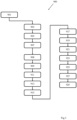
- the described system 1 can be exploited by a user inside a passenger compartment 51 of a vehicle 5 (as schematically illustrated in Figure 1 ), to implement a method 900 of driving assistance (illustrated by the flow chart of Figure 3 ) which is precise and reliable, while simultaneously requiring particularly limited hardware and software resources.
- a marker 40 is positioned inside the passenger compartment 51 of the vehicle 5 to operate as the main reference element and, preferably, a variable number of secondary markers 40, three in the example considered in the Figures, can be arranged in the passenger compartment to operate as secondary reference elements (block 901).
- the markers 40 are positioned on, or at, a windscreen 53 of the vehicle 5. This allows to identify an orientation and a position of the HMD 10 with respect to the markers 40 and therefore the field of view FOV of the HMD 10 and, possibly, a display region R of the screen 11 on which to display images - as described below.
- an exemplary arrangement - which allows the orientation and position of the HMD 10 to be identified in a particularly reliable way - includes positioning a first marker 40 at one left end of the windscreen 53, a second marker 40 in a frontal position with respect to the driver's position - without obstructing the view of the path -, and a third marker 40 at a median position of the windscreen 53 with respect to a lateral extension thereof.
- the method 900 includes a step for calibrating the system 1 which comprises an alignment procedure and a boresighting procedure.
- a relative position is first identified among the markers 40 positioned in the passenger compartment 51.
- the HMD 10 is worn by a user who maintains a predetermined driving posture; preferably, with the head - and, consequently, the HMD 10 - facing the windscreen 53 (for example, as shown in Figure 4a ).
- a pair of images A+ and A- is acquired through the cameras 15 (block 903) substantially at the same instant of time.
- a sequence of pairs of images A+ and A- is acquired during a time interval in which the HMD 10 is held in the same position or moved slowly (for example, due to normal posture corrections or changes carried out by the user wearing the HMD 10).
- both images A+ and A- will substantially reproduce the same field of view FOV of the HMD 10, but observed from different observation points f1 and f2 (as can be seen in Figures 5a - 5c ).
- the images A+ and A- of the cameras 15 are processed to recognize each marker 40 (block 905).
- the images A+ and A- are combined together so as to exploit stereoscopy to define and identify each marker 40 framed in the images A+ and A-.
- the images A+ and A- are identified shapes corresponding to the markers 40, while the single markers 40 are recognized by identifying the corresponding fiduciary pattern.
- the translation and orientation of each marker 40 is calculated with respect to a reference system associated with the HMD 10, that is, a three-dimensional reference system substantially centred in the point of view of the driver wearing the HMD 10 (block 907 and schematically illustrated in Figure 6 ).
- a translation value and a rotation value of the marker 40 with respect to each camera 15 are calculated, thus obtaining two pairs of measurements, which are subsequently combined - for example, by means of a suitable algorithm which implements averaging and/or correlation operations - to obtain corresponding combined rotation and orientation measurements associated with each marker 40.
- a scale value and/or correction factors can also be determined to compensate for deformations and/or aberrations introduced by the specific features of the cameras 15 used.
- the position and the calculated orientation of each marker 40 with respect to the HDM 10 is filtered over time to remove any noise.
- a main marker 40 is then selected, for example the marker 40 with the best visibility in the acquired images A+ and A- or the marker 40 having a predefined identification code, and they are calculated, preferably, by means of rototranslations - i.e., which link the position of each marker 40 to the position of the main marker 40 (block 908).
- the rototranslations which link the position of each marker 40 to the main marker 40 are calculated for each position of the marker 40 determined by analysing pairs of images A+ and A- acquired in successive instants of time. The rototranslations calculated for each marker 40 are then time-averaged in order to obtain a single rototranslation for each marker 40 with respect to the main marker 40.
- the alignment procedure allows to identify and, advantageously, store a respective rototranslation relationship which links the main marker 40 and each of the secondary markers 40 (as schematically represented by a dashed arrow in Figure 7 where the vector triads centred on the markers 40 represent respective reference systems centred on each marker 40 and the arrows represent the rototranslation operations which link the secondary markers 40 to the main marker 40).
- the boresighting procedure of the calibration step establishes a compensation law between the position of the GNSS module 20 and the actual position of the HMD 10 - with respect to the global reference system - and, therefore, allows to calculate an optimal display of images displayed on the HMD 10 based on the measurements provided by the GNSS module 20.
- the compensation law is defined by identifying a rototranslation relationship between the relative reference system associated with the reference marker 40 and the global reference system associated with the GNSS module 20.
- the vehicle 5, in particular the GNSS module 20 is positioned at a predetermined distance d and with a known orientation from an alignment object, or boresighting world point WPR, for example a real physical object (block 909).
- the boresighting position PWR associated with the boresighting world point WPR is therefore known.
- the Applicant has identified that a straight segment can be used as a boresighting world point WPR and allow a precise boresighting of the system 1.
- a polygonal figure and/or a three-dimensional object allow a user to complete the boresighting procedure with greater simplicity.
- the boresighting position PWR and the vehicle position PG measured by the GNSS module 20 are used to determine a corresponding (two-dimensional) boresighting image ARR to be displayed on the screen 11 of the HMD 10 (block 911).
- the boresighting image ARR has a shape such as to correspond to the boresighting world point WPR seen through the HMD 10.
- the visualization position PAR on the HMD 10 of the boresighting image ARR corresponds to a virtual boresighting position PVP associated with a corresponding virtual object, or virtual boresighting point VPR.
- the virtual boresighting point VPR is a virtual replica of the boresighting world point WPR, while the virtual boresighting position PVR is a replica - in the relative reference system of the HMD 10 - of the boresighting position PWR calculated on the basis of the vehicle position provided by the GNSS module 20.
- the boresighting procedure provides that the boresighting image ARR is translated along the screen 11 of the HMD 10 until the two-dimensional image ARR - in a new visualization position PAR' - overlaps the boresighting world point WPR - visible through the windscreen 53 of the vehicle 5 (block 913).
- the processing unit 30 may be configured to allow a user to move the boresighting image ARR, for example via a user interface (not shown) of the processing unit 30 or via a user interface of a device connected to the processing unit (for example the HMD 10 itself, or a personal computer, a smartphone, a tablet, an on-board computer of the vehicle 5, etc.).
- a user interface not shown
- a device connected to the processing unit for example the HMD 10 itself, or a personal computer, a smartphone, a tablet, an on-board computer of the vehicle 5, etc.
- the translation on the screen 11 of the HMD 10 which leads to the superimposition of the boresighting image ARR and the boresighting world point WPR is, therefore, processed to determine a compensation law capable of compensating for a discrepancy - or offset - between the boresighting image ARR and the boresighting world point WPR (block 915).
- the compensation law can be defined by a compensation matrix based on a rototranslation relationship between the virtual boresighting position PVR - associated with the virtual boresighting point VPR to which the boresighting image ARR corresponds - and the alignment position PWR - associated with the reference world point WPR.
- the boresighting procedure allows to simply and effectively determine a rototranslation relationship between the position of the GNSS module 20 and the position of the HMD 10, identifiable thanks to the detection of at least one of the markers 40 - i.e., a reference element integral with the vehicle 5.
- the rototranslation relationship relates the position of the GNSS module 20 to the position of at least one marker 40 located in a static position inside the passenger compartment 51 of the vehicle. This allows to precisely and accurately define the actual position of the HMD 10 in the global coordinate system used by the GNSS module 20.
- the compensation law allows to correct the error introduced by the different global position of the HMD 10 through which the user observes the environment and the global position detected by the GNSS module 20.
- the compensation law it is possible to correct the reproduction position of any image on the HMD 10 so that it corresponds to a relative world point WPR regardless of the movements of the HMD 10 inside the passenger compartment 51 due, for example, to movements of the head of the user wearing the HMD 10.
- the system 1 is able to display in real time on the HMD 10 one or more images AR1-3 associated with corresponding world points WP1-3, positioning them with high accuracy and precision on the screen 11 of the HMD 10 (as schematically illustrated in Figure 9 ).
- the pose of the HMD 10 with respect to the markers 40 (block 917) is determined.
- a relative position of the HMD 10 with respect to the marker 40 is determined, which is mounted inside the vehicle 5 and integral therewith.
- the calculation of the pose of each camera 15 with respect to each recognized marker 40 is performed.
- pairs of images A+ and A- are acquired by the cameras 15 to identify the relative position between cameras 15 and marker 40.
- the pose of each camera 15 with respect to a marker 40 can be identified, through an algorithm based on what is described in F. Ababsa, M. Mallem, "Robust Camera Pose Estimation Using 2D Fiducials Tracking for Real-Time Augmented Reality Systems” International conference on Virtual Reality continuum and its applications in industry, pp. 431-435, 2004 .
- the algorithm configured to identify the pose of the cameras can be based on the teachings contained in Madjid Maidi, Jean-Yves Didier, Fakhreddine Ababsa, Malik Mallem: "A performance study for camera pose estimation using visual marker-based tracking", published in Machine Vision and Application, Volume 21, Issue 3, pages 265-376, year 2010 , and/or in Francisco J. Romero-Ramirez, Rafael Munoz-Salinas, Rafael Medina-Carnicer: “Speeded Up Detection of Squared Fiducial Markers” published in Image and Vision Computing, Volume 76, year 2018 .
- the rotation and translation measurements are combined - for example, by means of an appropriate algorithm which implements averaging and/or correlation operations - to obtain corresponding measurements of rotation and orientation of the HMD 10 with respect to each of the identified markers 40.
- the rototranslation relationships between secondary markers 40 and main markers 40 determined in the calibration step are applied to the poses of the HMD 10 calculated with respect to the secondary markers 40 so as to obtain a set of poses of the HMD 10 all referred to the main marker 40, which are then combined with each other - for example, by means of an appropriate algorithm which implements averaging and/or correlation operations - in order to obtain a combined pose of the HMD 10 with respect to the main marker 40, which is particularly precise.
- the orientation and position of the HMD 10 with respect to the main marker 40 i.e., with respect to a relative reference system, are determined.
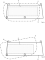
- one or more identified markers 40 can be used to define the shape and extent of a display region R of the screen 11 in which images will be displayed, for example so that the images are displayed superimposed on the windscreen 53 of the vehicle 5 or a portion thereof (as schematically illustrated in Figures 4a and 4b ).
- the vehicle position PG is detected through the GNSS module 20 (block 919).
- the vehicle position PG is then modified by applying the compensation law defined during the calibration step in order to determine the position of the HMD 10 with respect to the global reference system (block 921 and Figure 2 ).
- the vehicle position PG is modified through the rototranslation relationship determined during the boresighting procedure, allowing to convert the relative position of the HMD 10 determined with respect to the main marker 40 into a position referred to the global reference system - for example, geographic coordinates.
- the position and orientation of the HMD 10 with respect to the global reference system are determined in real time.
- a view volume VOL is determined, i.e., the volume of space comprised in the field of view FOV of the HMD 10 (block 923).
- the view volume VOL (schematically illustrated in Figure 2 ) extends within a distance - i.e., a depth of the field of view FOV - predetermined by a current position of the HMD 10 - possibly modified based on parameters acquired by the IMU 6 and/or by vehicle sensors 5 such as the speed and/or acceleration of the vehicle 5.
- a corresponding visualization position PA1-3 is calculated such that the user wearing the screen sees each image AR1-3 at the respective world point WP1-3 (block 927).
- the shape and other characteristics of the images AR1-3 can be based on information - for example, geometric information - relating to the corresponding world point WP0-3 - preferably, contained in the memory area 31 associated with the positions of interest PW0-3.
- each image AR1-3 is displayed if it is comprised in the display region R of the screen 11 superimposed on the windscreen 53 of the vehicle.
- the images AR1-3 can be generated so as to be displayed in the respective visualization positions PA1-3 corresponding to as many positions of interest PW1-3 by implementing an analogous algorithm of the 'worldToImage' function of the Computer Vision Toolbox TM comprised in the software product MATLAB ® and described in " Computer Vision ToolboxTM Reference” revision for version 9.0 (Release R2019a), March 2019 of The MathWorks, Inc .
- the method 900 provides for modifying the two-dimensional image AR, associated with a world point WP1-3 (for example, through variations in scale, perspective, etc.), as a function of the time and/or distance between the position of the HMD 10 and such world point WP1-3 (block 929).
- a pursuit or tracking of each world point WP1-3 is provided as long as it is comprised in the view volume VOL as a function of the movement of the vehicle 5 (for example, estimated based on the variation of the position of the vehicle 5).
- it is provided to dynamically modify the shape and/or position of the images AR1-3 displayed on the HMD 10 so that each of the images AR1-3 is correctly associated with the corresponding world point WP1-3.
- the method 900 allows to display on the HMD 10 two-dimensional images (such as driving trajectories, speed limits, information about road conditions, atmospheric conditions and/or relative to points of interest comprised in the FOV, such as cities, buildings, monuments, commercial establishments, etc.) which precisely and reliably integrate with what is visible in the field of view FOV of the user wearing the HMD 10.
- the method 900 is configured to modify in real time the shape and visualization position of the images AR1-3 displayed to adapt to position variations of both the vehicle 5 and the HMD 10.
- the processing unit 30 is configured to exploit the measurements acquired by the IMU and/or the sensors of the vehicle 5 in order to increase a positioning accuracy of the images on the HMD 10 and/or provide images containing more detailed and/or additional items of information.
- the possibility of scaling the boresighting image ARR can also be provided in order to guarantee an optimal overlap between the latter and the reference world point.
- the boresighting image ARR scaling operation can also be considered in evaluating the discrepancy between the boresighting image ARR and the reference world point WPR.
- the processing unit 30 can be configured to identify the boresighting world point WPR when framed in the field of view FOV of the HMD 10 and then superimpose the boresighting image ARR on the boresighting world point WPR automatically, or directly determine the discrepancy between the boresighting image ARR at the boresighting world point WPR automatically by applying one or more suitable algorithms.
- the method 900 provides for periodic access to the GNSS data database 7 in order to verify the presence of new world points in a geographic area of interest, for example in the view volume.
- the system 1 can be configured to operate using any number of markers 40.
- a pair of markers 40 or a single marker 40 can be used to determine the pose of the HMD 10 during the operative step of the method 900.
- This allows to adjust the computational load required by the system 1 to provide driving assistance in real time, with a better overall responsiveness of the system 1 to variations due to the movement of the vehicle 5 and/or of the world points WP0-3.
- this allows to adjust a relationship between the accuracy of identification of the pose of the HMD 10 and the computational load required of the processing unit 30.
- the method 900 provides for defining a relative virtual point with respect to at least one identified marker 40. If one or more secondary markers are identified, the rototranslation relationship is applied to the relative virtual points calculated with respect to the secondary markers in order to redefine these relative virtual points with respect to the main marker.
- a definitive virtual point is determined by combining all relative virtual points referring to the main marker - preferably, by means of an appropriate algorithm comprising, for example, averaging and/or correlation operations.
- the final virtual point is then converted into a corresponding image to be displayed by applying the compensation law in order to correct the position of the virtual point in the image defined in the two-dimensional reference system of the surface of the screen 11 of the HMD 10.
- a world point for example the world point WP0 in Figure 2
- a corresponding virtual indicator - for example, an arrow - is displayed on the HMD 10 - for example, reproduced at the edge of the display region R - with a tip pointing towards the position of the corresponding world point WP0.
- other information about the world point WP0 outside the display region R such as a name of the world point WP0, a distance, etc. can be displayed.
- the images AR can be reproduced with false colours based on the distance from the vehicle 5, a driving hazard associated with the relative world point and/or for conveying other information.
- reference elements 30 can be used such as one or more Data Matrix, QRcode, and/or other types of reference elements.
- markers 40 also composed of a different (greater or lesser) number of markers 40; finally, nothing prohibits having a single marker 40 to implement the method 900 described above.
- the markers 40 can be arranged in additional and/or alternative positions.
- one or more markers 40 can be positioned at one of the windows or on the rear window of the vehicle 5 in order to allow the reproduction of augmented reality images positioned correctly even when the user moves his gaze towards them.
- the markers 40 are made on the basis of the teachings contained in Francisco J. Romero-Ramirez, Rafael Mu ⁇ oz-Salinas, Rafael Medina-Carnicer: "Speeded up detection of squared fiducial markers” published in Image and Vision Computing, volume 76, pages 38-47, year 2018 ; in S. Garrido-Jurado, R. Mu ⁇ oz Salinas, F.J. Madrid-Cuevas, R.
- Medina-Carnicer "Generation of fiducial marker dictionaries using mixed integer linear programming” published in Pattern Recognition volume 51, pages 481-491, year 2016 , and/or in Garrido-Jurado, Sergio, et al.: "Automatic generation and detection of highly reliable fiducial markers under occlusion” published in Pattern Recognition, volume 47, number 6, pages 2280-2292, year 2014 .
- markers 40 are particularly advantageous, nothing prohibits the implementation of alternative methods in which the position and orientation of the HMD with respect to the windscreen and/or other elements of the passenger compartment are identified differently, for example through the use of video and/or photo cameras aimed at the driver and/or one or more motion sensors mounted on the HMD.
- the system 1 can be provided as a kit of components to be assembled inside the passenger compartment of a vehicle.
- the kit comprises at least a processing unit 30, a dedicated GNSS module 20 - or, alternatively, a wired and/or wireless connection element between processing units to a GNSS module of the vehicle and an HMD 10, preferably, comprising two cameras 10, and connectable to the processing unit.
- the processing unit 30 can be configured to operate with one or more commercially available HMDs (e.g., Microsoft HoloLens). Therefore one or more versions of the kit does not necessarily comprise an HMD.
- connections between the elements of the system 1 - in particular, between the processing unit 30 and the HMD 10 - can be both of the wired type and, preferably, wireless.
- connection with the elements of the system 1 and other elements - for example, between the processing unit 30 and the IMU, the ECU (not shown) of the vehicle 5, the infotainment system (not shown) of the vehicle 5, etc. - can be either wired or wireless.
Landscapes
- Engineering & Computer Science (AREA)
- Physics & Mathematics (AREA)
- Radar, Positioning & Navigation (AREA)
- General Physics & Mathematics (AREA)
- Remote Sensing (AREA)
- Theoretical Computer Science (AREA)
- Automation & Control Theory (AREA)
- General Engineering & Computer Science (AREA)
- Optics & Photonics (AREA)
- Human Computer Interaction (AREA)
- Computer Vision & Pattern Recognition (AREA)
- Processing Or Creating Images (AREA)
- Navigation (AREA)
- Controls And Circuits For Display Device (AREA)
- Image Processing (AREA)
- Automatic Cycles, And Cycles In General (AREA)
- Traffic Control Systems (AREA)
Claims (10)
- Verfahren (900) zur Unterstützung des Steuerns eines Fahrzeugs (5), umgesetzt durch ein System (1) aufweisend ein HMD (10), ein Referenzelement (40), welches innerhalb des Fahrzeugs (5) angeordnet ist, und ein Positionierungsmodul (20), welches an dem Fahrzeug (5) befestigt ist, wobei das Verfahren (900) folgende Schritte aufweist:- Erfassen (919) einer Fahrzeugposition mittels des Positionierungsmoduls (20), wobei die Position in Bezug auf ein globales Referenzsystem definiert wird;- Bestimmen einer Position des HMD (10)in Bezug auf das globale Referenzsystem, basierend auf der erfassten Position des Fahrzeugs (5);- Bestimmen (923) eines Sichtvolumens (VOL), welches einem Raumvolumen innerhalb des Sichtbereichs (FOV) des HMD (10) entspricht, basierend auf der Position des HMD (10);- Vergleichen (925) einer Zahl von Positionen in dem Sichtvolumen mit mindestens einer Position von Interesse (PW1-3), welche mit einem Objekt von Interesse (WP1-3), welches in einem Speicherbereich (31) des Systems (1) gespeichert ist, assoziiert ist, und- Berechnen (927) einer Darstellungsposition (PA1-3) des HMD (10), in welcher ein mit dem Objekt von Interesse (WP1-3) assoziiertes Bild (AR1-3) dargestellt werden soll, falls eine oder mehrere der Positionen von Interesse (PW1-3) in dem Sichtvolumen (VOL) enthalten sind, und Anzeigen des Bildes (AR1-3) auf dem HMD (10) in der Darstellungsposition (PA1-3), wobei die Darstellungsposition (PA1-3) derart ausgestaltet ist, dass ein das HMD (10) tragender Benutzer das Bild (PA1-3) in Verbindung mit dem Objekt von Interesse (WP1-3) sieht,wobei Schritt des Bestimmens einer Position des HMD (10) in Bezug auf das globale Referenzsystem basierend auf der erfassten Position des Fahrzeugs (5) aufweist:- Bestimmen (909-915) einer Ausgleichsregel, welche durch Identifizieren einer Drehverschiebungs-Beziehung zwischen dem globalen Referenzsystem und einem relativen Referenzsystem, welches mit dem Referenzelement (40) assoziiert ist, definiert wird;- Erfassen von zumindest einem Bild des sich innerhalb des Fahrzeugs (5) befindenden Referenzelements (40) mittels des HMD (10);- Bestimmen (917) einer relativen Position des HMD (10) in Bezug auf das Referenzelement (40) durch Verarbeiten des erfassten Bildes, wobei sich die relative Position auf das relative Referenzsystem, welches mit dem Referenzelement (40) assoziiert ist, bezieht;- Umwandeln (921) der relativen Position des HMD (10) in Bezug auf das Referenzelement (40) in eine entsprechende Position in Bezug auf das globale Referenzsystem durch Anwenden der Drehverschiebungs-Beziehung.
- Verfahren (900) nach Anspruch 1, wobei das HMD (10) mindestens zwei Videokameras (15), welche an gegenüberliegenden Seiten eines Bildschirms (11) des HMD (10) angeordnet sind, aufweist, und wobei der Schritt des Bestimmens (917) einer relativen Position des HMD (10) in Bezug auf das Referenzelement (40) aufweist:- Verwenden jeder Kamera (15) des HMD (10) zur Erfassung eines Bildes des sich innerhalb des Fahrzeugs (5) befindenden Referenzelements (40);- Berechnen einer relativen Position jeder Kamera (15) in Bezug auf das Referenzelement (40) durch Verarbeiten des entsprechenden erfassten Bildes;- Berechnen der relativen Position des HMD (10) in Bezug auf das Referenzelement (40) durch Kombinieren der relativen Positionen der Kameras (15).
- Verfahren (900) nach Anspruch 1 oder 2, wobei das System (1) eine Vielzahl von Referenzelementen (40) aufweist, wobei ein ausgewähltes Referenzelement als Hauptreferenzelement agiert und die übrigen Referenzelemente als Nebenreferenzelemente agieren, wobei das Verfahren (900) weiterhin folgenden Schritt aufweist:- Berechnen (903-908) einer Bezugsbeziehung, welche einer Drehverschiebungs-Beziehung zwischen dem Nebenreferenzelement und dem Hauptreferenzelement entspricht, für jedes Nebenreferenzelement;wobei der Schritt des Bestimmens (917) einer relativen Position des HMD (10) in Bezug auf das Referenzelement (40) aufweist:- Berechnen der relativen Position des HMD (10) in Bezug auf zumindest zwei Referenzelemente (40), welche aus einer Menge beinhaltend das Hauptreferenzelement und die Nebenreferenzelemente ausgewählt werden;- Anwenden der Drehverschiebungs-Beziehung auf die relative Position des HMD (10), welche in Bezug auf jedes ausgewählte Nebenreferenzelement berechnet wurde;- Berechnen einer kombinierten relativen Position des HMD (10) in Bezug auf das Hauptreferenzelement durch Kombinieren der relativen Positionen, welche in Bezug auf die mindestens zwei Referenzelemente berechnet wurden, nachdem die Drehverschiebungs-Beziehung auf die relative Position des HMD (10), welche in Bezug auf jedes ausgewählte Nebenreferenzelement berechnet wurde, angewandt wurde.
- Verfahren (900) nach einem der vorhergehenden Ansprüche, wobei der Schritt des Bestimmens (923) eines Sichtvolumens (VOL) aufweist:- Berechnen einer Ausrichtung des HMD (10) in Bezug auf das Referenzelement (40) durch Verarbeiten des mindestens einen erfassten Bildes; und- Bestimmen des Sichtbereichs (FOV) des HMD (10) basierend auf der globalen Position des HMD (10) und der Ausrichtung des HMD (10) in Bezug auf das Referenzelement (40).
- Verfahren (900) nach einem der vorhergehenden Ansprüche, weiterhin aufweisend folgende Schritten:- Auswählen (909) einer Mittelachsenposition (PWR);- Anzeigen (911) eines Mittelachsenbildes (ARR) in einer Darstellungsposition (PAR) des HMD (10), wobei die Darstellungsposition (PAR) gemäß der Mittelachsenposition (PWR) und der Fahrzeugposition berechnet wird;- Messen (913) einer Positionsabweichung zwischen der Mittelachsenposition (PWR) und der Darstellungsposition (PAR), und- Bestimmen (915) der Ausgleichsregel basierend auf der Positionsabweichung.
- Verfahren (900) nach Anspruch 5, wobei das Messen einer Abweichungsposition zwischen der Mittelachsenposition (PWR) und der Darstellungsposition (PAR) aufweist:- Definieren einer Drehverschiebungs-Beziehung zwischen einer virtuellen Mittelachsenposition (PVR) und der Mittelachsenposition (PWR), wobei die virtuelle Mittelachsenposition (PVR) der Projizierung der Darstellungsposition (PAR) in einem dreidimensionalen Referenzsystem entspricht, undwobei das Bestimmen der Ausgleichsregel aufweist:- Verwenden der Drehverschiebungs-Beziehung zur Bestimmung der Ausgleichsregel.
- Verfahren (900) nach Anspruch 6, wobei die Mittelachsenposition (PW) in einem Mittelachsenobjekt angeordnet ist, und
wobei das Definieren einer Drehverschiebungs-Beziehung aufweist:- Ausrichten des HMD (10) derart, dass der Sichtbereich (FOV) des HMD (10) das Mittelachsenobjekt beinhaltet;- Verschieben des auf dem HMD (10) angezeigten Mittelachsenbildes (ARR) bis ein Überlappen des Mittelachsenbildes (ARR) mit dem Mittelachsenobjekt (WPR) in der Mittelachsenposition (PWR) erreicht wird, und- Umwandeln des Verschiebens des Mittelachsenbildes (ARR) in einem zweidimensionalen Referenzsystem in eine Drehung und eine Verschiebung der virtuellen Mittelachsenposition (PVR) in dem dreidimensionalen Referenzsystem. - Verfahren (900) nach einem der vorhergehenden Ansprüche, weiterhin aufweisend folgenden Schritt:- Erfassen von Fahrzeugbewegungsinformation (5) und,wobei der Schritt des Anzeigens eines Bildes, welches mit dem Objekt von Interesse (WP1-3) assoziiert ist, auf dem HMD (10) aufweist:- Abändern des Bildes als eine Funktion der Bewegung des Fahrzeugs (5) und Zeit.
- System (1) zur Unterstützung des Lenkens eines Fahrzeugs (5), aufweisend:- ein HMD (10);- mindestens ein Referenzelement (40), welches innerhalb des Fahrzeugs (5) angeordnet ist;- ein Positionierungsmodul (20), welches an dem Fahrzeug (5) befestigt ist und dazu ausgebildet ist, eine Position des Fahrzeugs (5) zu erfassen,- ein Speicherbereich (31), in welchem mindestens eine Position von Interesse, welche mit einem Objekt von Interesse assoziiert ist, gespeichert ist, und- eine Verarbeitungseinheit (30), welche operativ mit dem Positionierungsmodul (20) und dem HMD (10) verbunden ist und dazu ausgebildet ist, das Verfahren (900) nach einem der vorhergehenden Ansprüche auszuführen.
- System (1) nach Anspruch 9, wobei die Verarbeitungseinheit (30) operativ verbunden ist mit zumindest einem von:- einem BUS (55) zur Fahrzeugkommunikation (5), und- einer inertialen Messeinheit,um Fahrzeuginformationen (5) zu erfassen.
Applications Claiming Priority (2)
| Application Number | Priority Date | Filing Date | Title |
|---|---|---|---|
| IT102019000017429A IT201900017429A1 (it) | 2019-09-27 | 2019-09-27 | Metodo e sistema per l'assistenza alla guida di un veicolo |
| PCT/IB2020/058765 WO2021059107A1 (en) | 2019-09-27 | 2020-09-21 | Method and system of vehicle driving assistance |
Publications (3)
| Publication Number | Publication Date |
|---|---|
| EP4034841A1 EP4034841A1 (de) | 2022-08-03 |
| EP4034841B1 true EP4034841B1 (de) | 2024-10-30 |
| EP4034841C0 EP4034841C0 (de) | 2024-10-30 |
Family
ID=69469060
Family Applications (1)
| Application Number | Title | Priority Date | Filing Date |
|---|---|---|---|
| EP20800987.8A Active EP4034841B1 (de) | 2019-09-27 | 2020-09-21 | Verfahren und system zur fahrzeugfahrunterstützung |
Country Status (8)
| Country | Link |
|---|---|
| US (1) | US20220326028A1 (de) |
| EP (1) | EP4034841B1 (de) |
| JP (1) | JP7659837B2 (de) |
| CN (1) | CN114503008B (de) |
| CA (1) | CA3152294A1 (de) |
| ES (1) | ES3006935T3 (de) |
| IT (1) | IT201900017429A1 (de) |
| WO (1) | WO2021059107A1 (de) |
Families Citing this family (6)
| Publication number | Priority date | Publication date | Assignee | Title |
|---|---|---|---|---|
| WO2021050561A2 (en) | 2019-09-09 | 2021-03-18 | Mtd Products Inc | Real time kinematics power equipment device with auto-steering |
| IT202100007862A1 (it) * | 2021-03-30 | 2022-09-30 | Milano Politecnico | Metodo e sistema di assistenza alla guida di un veicolo |
| US11562550B1 (en) * | 2021-10-06 | 2023-01-24 | Qualcomm Incorporated | Vehicle and mobile device interface for vehicle occupant assistance |
| US12277779B2 (en) | 2021-10-06 | 2025-04-15 | Qualcomm Incorporated | Vehicle and mobile device interface for vehicle occupant assistance |
| US12198291B2 (en) * | 2022-01-12 | 2025-01-14 | Htc Corporation | Method for adjusting virtual object, host, and computer readable storage medium |
| CN116631307A (zh) * | 2023-04-10 | 2023-08-22 | 湖北星纪魅族科技有限公司 | 显示方法、智能穿戴设备、电子设备、装置和存储介质 |
Family Cites Families (11)
| Publication number | Priority date | Publication date | Assignee | Title |
|---|---|---|---|---|
| US20020105484A1 (en) * | 2000-09-25 | 2002-08-08 | Nassir Navab | System and method for calibrating a monocular optical see-through head-mounted display system for augmented reality |
| JP2004219664A (ja) * | 2003-01-14 | 2004-08-05 | Sumitomo Electric Ind Ltd | 情報表示システム及び情報表示方法 |
| KR101544524B1 (ko) * | 2010-12-16 | 2015-08-17 | 한국전자통신연구원 | 차량용 증강현실 디스플레이 시스템 및 차량용 증강현실 디스플레이 방법 |
| US9715764B2 (en) * | 2013-10-03 | 2017-07-25 | Honda Motor Co., Ltd. | System and method for dynamic in-vehicle virtual reality |
| WO2015123774A1 (en) * | 2014-02-18 | 2015-08-27 | Sulon Technologies Inc. | System and method for augmented reality and virtual reality applications |
| EP2933707B1 (de) * | 2014-04-14 | 2017-12-06 | iOnRoad Technologies Ltd. | Darstellungseinstellung für kopfmontierte Anzeige |
| US9626802B2 (en) * | 2014-05-01 | 2017-04-18 | Microsoft Technology Licensing, Llc | Determining coordinate frames in a dynamic environment |
| US20160084661A1 (en) | 2014-09-23 | 2016-03-24 | GM Global Technology Operations LLC | Performance driving system and method |
| IL235073A (en) * | 2014-10-07 | 2016-02-29 | Elbit Systems Ltd | Head-mounted view of enlarged images that are locked on an object of interest |
| CN107757479A (zh) * | 2016-08-22 | 2018-03-06 | 何长伟 | 一种基于增强现实显示技术的驾驶辅助系统及方法 |
| US11727646B2 (en) * | 2019-04-10 | 2023-08-15 | Trimble Inc. | Augmented reality image occlusion |
-
2019
- 2019-09-27 IT IT102019000017429A patent/IT201900017429A1/it unknown
-
2020
- 2020-09-21 ES ES20800987T patent/ES3006935T3/es active Active
- 2020-09-21 WO PCT/IB2020/058765 patent/WO2021059107A1/en not_active Ceased
- 2020-09-21 CN CN202080067235.6A patent/CN114503008B/zh active Active
- 2020-09-21 EP EP20800987.8A patent/EP4034841B1/de active Active
- 2020-09-21 CA CA3152294A patent/CA3152294A1/en active Pending
- 2020-09-21 US US17/639,948 patent/US20220326028A1/en not_active Abandoned
- 2020-09-21 JP JP2022509025A patent/JP7659837B2/ja active Active
Also Published As
| Publication number | Publication date |
|---|---|
| EP4034841A1 (de) | 2022-08-03 |
| US20220326028A1 (en) | 2022-10-13 |
| IT201900017429A1 (it) | 2021-03-27 |
| JP2022549562A (ja) | 2022-11-28 |
| ES3006935T3 (en) | 2025-03-19 |
| CA3152294A1 (en) | 2021-04-01 |
| CN114503008A (zh) | 2022-05-13 |
| CN114503008B (zh) | 2024-11-19 |
| WO2021059107A1 (en) | 2021-04-01 |
| EP4034841C0 (de) | 2024-10-30 |
| JP7659837B2 (ja) | 2025-04-10 |
Similar Documents
| Publication | Publication Date | Title |
|---|---|---|
| EP4034841B1 (de) | Verfahren und system zur fahrzeugfahrunterstützung | |
| US6956503B2 (en) | Image display apparatus, image display method, measurement apparatus, measurement method, information processing method, information processing apparatus, and identification method | |
| US11181737B2 (en) | Head-up display device for displaying display items having movement attribute or fixed attribute, display control method, and control program | |
| CN107228681A (zh) | 一种通过摄像头加强导航功能的导航系统 | |
| CN107235013A (zh) | 车载导航定位全景云台 | |
| CN102778754B (zh) | 用于使车辆的投影装置的投影对齐的方法和装置 | |
| CN105676452A (zh) | 用于车辆的增强现实hud显示方法和装置 | |
| US10891791B2 (en) | Detection and visualization of system uncertainty in the representation of augmented image content in heads-up displays | |
| CN114167470A (zh) | 一种数据处理方法和装置 | |
| KR20170060652A (ko) | 헤드업 디스플레이의 좌표 매칭 장치 및 그 방법 | |
| CN111094898A (zh) | 用于控制用于机动车辆的增强现实抬头显示设备的显示的方法、设备和具有指令的计算机可读存储介质 | |
| EP3848781B1 (de) | Schaltungsvorrichtung, elektronische einrichtung und mobiler körper | |
| JP5915268B2 (ja) | パラメータ算出方法、情報処理装置及びプログラム | |
| WO2004048895A1 (ja) | 移動体ナビゲート情報表示方法および移動体ナビゲート情報表示装置 | |
| CN112424567B (zh) | 用于辅助导航的方法 | |
| CN112781620B (zh) | 一种基于高精度地图系统的ar-hud影像标定调整系统及方法 | |
| Savaresi et al. | METHOD AND SYSTEM OF VEHICLE DRIVING ASSISTANCE | |
| US12380610B2 (en) | Driving assistance method and system | |
| US11210519B2 (en) | Providing augmented reality images to an operator of a machine | |
| CN111512120A (zh) | 用于显示增强现实poi信息的方法、装置和系统 | |
| KR20180026418A (ko) | 헤드업 디스플레이의 좌표 매칭 장치 및 그 방법 | |
| Corno et al. | DRIVING ASSISTANCE METHOD AND SYSTEM | |
| CN117218193A (zh) | 真实物体的虚实贴合方法、智能座舱、介质及智能汽车 | |
| JPH1191468A (ja) | 車両用安全確認装置 |
Legal Events
| Date | Code | Title | Description |
|---|---|---|---|
| STAA | Information on the status of an ep patent application or granted ep patent |
Free format text: STATUS: UNKNOWN |
|
| STAA | Information on the status of an ep patent application or granted ep patent |
Free format text: STATUS: THE INTERNATIONAL PUBLICATION HAS BEEN MADE |
|
| PUAI | Public reference made under article 153(3) epc to a published international application that has entered the european phase |
Free format text: ORIGINAL CODE: 0009012 |
|
| STAA | Information on the status of an ep patent application or granted ep patent |
Free format text: STATUS: REQUEST FOR EXAMINATION WAS MADE |
|
| 17P | Request for examination filed |
Effective date: 20220427 |
|
| AK | Designated contracting states |
Kind code of ref document: A1 Designated state(s): AL AT BE BG CH CY CZ DE DK EE ES FI FR GB GR HR HU IE IS IT LI LT LU LV MC MK MT NL NO PL PT RO RS SE SI SK SM TR |
|
| DAV | Request for validation of the european patent (deleted) | ||
| DAX | Request for extension of the european patent (deleted) | ||
| REG | Reference to a national code |
Ref country code: DE Ipc: G02B0027000000 Ref country code: DE Ref legal event code: R079 Ref document number: 602020040422 Country of ref document: DE Free format text: PREVIOUS MAIN CLASS: G01C0021360000 Ipc: G02B0027000000 |
|
| RIC1 | Information provided on ipc code assigned before grant |
Ipc: G01C 21/00 20060101ALI20240625BHEP Ipc: G02B 27/01 20060101ALI20240625BHEP Ipc: G06F 3/01 20060101ALI20240625BHEP Ipc: G01C 21/36 20060101ALI20240625BHEP Ipc: G02B 27/00 20060101AFI20240625BHEP |
|
| GRAP | Despatch of communication of intention to grant a patent |
Free format text: ORIGINAL CODE: EPIDOSNIGR1 |
|
| STAA | Information on the status of an ep patent application or granted ep patent |
Free format text: STATUS: GRANT OF PATENT IS INTENDED |
|
| INTG | Intention to grant announced |
Effective date: 20240823 |
|
| GRAS | Grant fee paid |
Free format text: ORIGINAL CODE: EPIDOSNIGR3 |
|
| GRAA | (expected) grant |
Free format text: ORIGINAL CODE: 0009210 |
|
| STAA | Information on the status of an ep patent application or granted ep patent |
Free format text: STATUS: THE PATENT HAS BEEN GRANTED |
|
| AK | Designated contracting states |
Kind code of ref document: B1 Designated state(s): AL AT BE BG CH CY CZ DE DK EE ES FI FR GB GR HR HU IE IS IT LI LT LU LV MC MK MT NL NO PL PT RO RS SE SI SK SM TR |
|
| REG | Reference to a national code |
Ref country code: GB Ref legal event code: FG4D |
|
| REG | Reference to a national code |
Ref country code: CH Ref legal event code: EP |
|
| REG | Reference to a national code |
Ref country code: IE Ref legal event code: FG4D |
|
| REG | Reference to a national code |
Ref country code: DE Ref legal event code: R096 Ref document number: 602020040422 Country of ref document: DE |
|
| U01 | Request for unitary effect filed |
Effective date: 20241128 |
|
| U07 | Unitary effect registered |
Designated state(s): AT BE BG DE DK EE FI FR IT LT LU LV MT NL PT RO SE SI Effective date: 20241209 |
|
| REG | Reference to a national code |
Ref country code: ES Ref legal event code: FG2A Ref document number: 3006935 Country of ref document: ES Kind code of ref document: T3 Effective date: 20250319 |
|
| PG25 | Lapsed in a contracting state [announced via postgrant information from national office to epo] |
Ref country code: IS Free format text: LAPSE BECAUSE OF FAILURE TO SUBMIT A TRANSLATION OF THE DESCRIPTION OR TO PAY THE FEE WITHIN THE PRESCRIBED TIME-LIMIT Effective date: 20250228 Ref country code: HR Free format text: LAPSE BECAUSE OF FAILURE TO SUBMIT A TRANSLATION OF THE DESCRIPTION OR TO PAY THE FEE WITHIN THE PRESCRIBED TIME-LIMIT Effective date: 20241030 |
|
| PG25 | Lapsed in a contracting state [announced via postgrant information from national office to epo] |
Ref country code: NO Free format text: LAPSE BECAUSE OF FAILURE TO SUBMIT A TRANSLATION OF THE DESCRIPTION OR TO PAY THE FEE WITHIN THE PRESCRIBED TIME-LIMIT Effective date: 20250130 |
|
| PG25 | Lapsed in a contracting state [announced via postgrant information from national office to epo] |
Ref country code: GR Free format text: LAPSE BECAUSE OF FAILURE TO SUBMIT A TRANSLATION OF THE DESCRIPTION OR TO PAY THE FEE WITHIN THE PRESCRIBED TIME-LIMIT Effective date: 20250131 |
|
| PG25 | Lapsed in a contracting state [announced via postgrant information from national office to epo] |
Ref country code: PL Free format text: LAPSE BECAUSE OF FAILURE TO SUBMIT A TRANSLATION OF THE DESCRIPTION OR TO PAY THE FEE WITHIN THE PRESCRIBED TIME-LIMIT Effective date: 20241030 |
|
| PG25 | Lapsed in a contracting state [announced via postgrant information from national office to epo] |
Ref country code: RS Free format text: LAPSE BECAUSE OF FAILURE TO SUBMIT A TRANSLATION OF THE DESCRIPTION OR TO PAY THE FEE WITHIN THE PRESCRIBED TIME-LIMIT Effective date: 20250130 |
|
| PG25 | Lapsed in a contracting state [announced via postgrant information from national office to epo] |
Ref country code: SM Free format text: LAPSE BECAUSE OF FAILURE TO SUBMIT A TRANSLATION OF THE DESCRIPTION OR TO PAY THE FEE WITHIN THE PRESCRIBED TIME-LIMIT Effective date: 20241030 |
|
| PG25 | Lapsed in a contracting state [announced via postgrant information from national office to epo] |
Ref country code: SK Free format text: LAPSE BECAUSE OF FAILURE TO SUBMIT A TRANSLATION OF THE DESCRIPTION OR TO PAY THE FEE WITHIN THE PRESCRIBED TIME-LIMIT Effective date: 20241030 |
|
| PG25 | Lapsed in a contracting state [announced via postgrant information from national office to epo] |
Ref country code: CZ Free format text: LAPSE BECAUSE OF FAILURE TO SUBMIT A TRANSLATION OF THE DESCRIPTION OR TO PAY THE FEE WITHIN THE PRESCRIBED TIME-LIMIT Effective date: 20241030 |
|
| PLBE | No opposition filed within time limit |
Free format text: ORIGINAL CODE: 0009261 |
|
| STAA | Information on the status of an ep patent application or granted ep patent |
Free format text: STATUS: NO OPPOSITION FILED WITHIN TIME LIMIT |
|
| REG | Reference to a national code |
Ref country code: CH Ref legal event code: U11 Free format text: ST27 STATUS EVENT CODE: U-0-0-U10-U11 (AS PROVIDED BY THE NATIONAL OFFICE) Effective date: 20251001 |
|
| 26N | No opposition filed |
Effective date: 20250731 |
|
| PGFP | Annual fee paid to national office [announced via postgrant information from national office to epo] |
Ref country code: GB Payment date: 20250927 Year of fee payment: 6 |
|
| U20 | Renewal fee for the european patent with unitary effect paid |
Year of fee payment: 6 Effective date: 20250926 |