EP4034362B1 - Gegenstände, die platten und geformte strukturen einschliessen, und verfahren zu deren herstellung - Google Patents
Gegenstände, die platten und geformte strukturen einschliessen, und verfahren zu deren herstellung Download PDFInfo
- Publication number
- EP4034362B1 EP4034362B1 EP20780355.2A EP20780355A EP4034362B1 EP 4034362 B1 EP4034362 B1 EP 4034362B1 EP 20780355 A EP20780355 A EP 20780355A EP 4034362 B1 EP4034362 B1 EP 4034362B1
- Authority
- EP
- European Patent Office
- Prior art keywords
- panel
- layer
- injection molding
- molding die
- molded structure
- Prior art date
- Legal status (The legal status is an assumption and is not a legal conclusion. Google has not performed a legal analysis and makes no representation as to the accuracy of the status listed.)
- Active
Links
Images


Classifications
-
- B—PERFORMING OPERATIONS; TRANSPORTING
- B29—WORKING OF PLASTICS; WORKING OF SUBSTANCES IN A PLASTIC STATE IN GENERAL
- B29C—SHAPING OR JOINING OF PLASTICS; SHAPING OF MATERIAL IN A PLASTIC STATE, NOT OTHERWISE PROVIDED FOR; AFTER-TREATMENT OF THE SHAPED PRODUCTS, e.g. REPAIRING
- B29C45/00—Injection moulding, i.e. forcing the required volume of moulding material through a nozzle into a closed mould; Apparatus therefor
- B29C45/14—Injection moulding, i.e. forcing the required volume of moulding material through a nozzle into a closed mould; Apparatus therefor incorporating preformed parts or layers, e.g. injection moulding around inserts or for coating articles
- B29C45/1418—Injection moulding, i.e. forcing the required volume of moulding material through a nozzle into a closed mould; Apparatus therefor incorporating preformed parts or layers, e.g. injection moulding around inserts or for coating articles the inserts being deformed or preformed, e.g. by the injection pressure
-
- B—PERFORMING OPERATIONS; TRANSPORTING
- B32—LAYERED PRODUCTS
- B32B—LAYERED PRODUCTS, i.e. PRODUCTS BUILT-UP OF STRATA OF FLAT OR NON-FLAT, e.g. CELLULAR OR HONEYCOMB, FORM
- B32B3/00—Layered products comprising a layer with external or internal discontinuities or unevennesses, or a layer of non-planar shape; Layered products comprising a layer having particular features of form
- B32B3/10—Layered products comprising a layer with external or internal discontinuities or unevennesses, or a layer of non-planar shape; Layered products comprising a layer having particular features of form characterised by a discontinuous layer, i.e. formed of separate pieces of material
- B32B3/12—Layered products comprising a layer with external or internal discontinuities or unevennesses, or a layer of non-planar shape; Layered products comprising a layer having particular features of form characterised by a discontinuous layer, i.e. formed of separate pieces of material characterised by a layer of regularly- arranged cells, e.g. a honeycomb structure
-
- B—PERFORMING OPERATIONS; TRANSPORTING
- B32—LAYERED PRODUCTS
- B32B—LAYERED PRODUCTS, i.e. PRODUCTS BUILT-UP OF STRATA OF FLAT OR NON-FLAT, e.g. CELLULAR OR HONEYCOMB, FORM
- B32B5/00—Layered products characterised by the non- homogeneity or physical structure, i.e. comprising a fibrous, filamentary, particulate or foam layer; Layered products characterised by having a layer differing constitutionally or physically in different parts
- B32B5/18—Layered products characterised by the non- homogeneity or physical structure, i.e. comprising a fibrous, filamentary, particulate or foam layer; Layered products characterised by having a layer differing constitutionally or physically in different parts characterised by features of a layer of foamed material
- B32B5/20—Layered products characterised by the non- homogeneity or physical structure, i.e. comprising a fibrous, filamentary, particulate or foam layer; Layered products characterised by having a layer differing constitutionally or physically in different parts characterised by features of a layer of foamed material foamed in situ
-
- G—PHYSICS
- G10—MUSICAL INSTRUMENTS; ACOUSTICS
- G10K—SOUND-PRODUCING DEVICES; METHODS OR DEVICES FOR PROTECTING AGAINST, OR FOR DAMPING, NOISE OR OTHER ACOUSTIC WAVES IN GENERAL; ACOUSTICS NOT OTHERWISE PROVIDED FOR
- G10K11/00—Methods or devices for transmitting, conducting or directing sound in general; Methods or devices for protecting against, or for damping, noise or other acoustic waves in general
- G10K11/16—Methods or devices for protecting against, or for damping, noise or other acoustic waves in general
- G10K11/162—Selection of materials
- G10K11/168—Plural layers of different materials, e.g. sandwiches
-
- B—PERFORMING OPERATIONS; TRANSPORTING
- B29—WORKING OF PLASTICS; WORKING OF SUBSTANCES IN A PLASTIC STATE IN GENERAL
- B29C—SHAPING OR JOINING OF PLASTICS; SHAPING OF MATERIAL IN A PLASTIC STATE, NOT OTHERWISE PROVIDED FOR; AFTER-TREATMENT OF THE SHAPED PRODUCTS, e.g. REPAIRING
- B29C45/00—Injection moulding, i.e. forcing the required volume of moulding material through a nozzle into a closed mould; Apparatus therefor
- B29C45/14—Injection moulding, i.e. forcing the required volume of moulding material through a nozzle into a closed mould; Apparatus therefor incorporating preformed parts or layers, e.g. injection moulding around inserts or for coating articles
- B29C45/1418—Injection moulding, i.e. forcing the required volume of moulding material through a nozzle into a closed mould; Apparatus therefor incorporating preformed parts or layers, e.g. injection moulding around inserts or for coating articles the inserts being deformed or preformed, e.g. by the injection pressure
- B29C2045/14237—Injection moulding, i.e. forcing the required volume of moulding material through a nozzle into a closed mould; Apparatus therefor incorporating preformed parts or layers, e.g. injection moulding around inserts or for coating articles the inserts being deformed or preformed, e.g. by the injection pressure the inserts being deformed or preformed outside the mould or mould cavity
- B29C2045/14245—Injection moulding, i.e. forcing the required volume of moulding material through a nozzle into a closed mould; Apparatus therefor incorporating preformed parts or layers, e.g. injection moulding around inserts or for coating articles the inserts being deformed or preformed, e.g. by the injection pressure the inserts being deformed or preformed outside the mould or mould cavity using deforming or preforming means outside the mould cavity
-
- B—PERFORMING OPERATIONS; TRANSPORTING
- B29—WORKING OF PLASTICS; WORKING OF SUBSTANCES IN A PLASTIC STATE IN GENERAL
- B29C—SHAPING OR JOINING OF PLASTICS; SHAPING OF MATERIAL IN A PLASTIC STATE, NOT OTHERWISE PROVIDED FOR; AFTER-TREATMENT OF THE SHAPED PRODUCTS, e.g. REPAIRING
- B29C45/00—Injection moulding, i.e. forcing the required volume of moulding material through a nozzle into a closed mould; Apparatus therefor
- B29C45/14—Injection moulding, i.e. forcing the required volume of moulding material through a nozzle into a closed mould; Apparatus therefor incorporating preformed parts or layers, e.g. injection moulding around inserts or for coating articles
- B29C45/14467—Joining articles or parts of a single article
- B29C2045/14532—Joining articles or parts of a single article injecting between two sheets
-
- B—PERFORMING OPERATIONS; TRANSPORTING
- B29—WORKING OF PLASTICS; WORKING OF SUBSTANCES IN A PLASTIC STATE IN GENERAL
- B29C—SHAPING OR JOINING OF PLASTICS; SHAPING OF MATERIAL IN A PLASTIC STATE, NOT OTHERWISE PROVIDED FOR; AFTER-TREATMENT OF THE SHAPED PRODUCTS, e.g. REPAIRING
- B29C45/00—Injection moulding, i.e. forcing the required volume of moulding material through a nozzle into a closed mould; Apparatus therefor
- B29C45/14—Injection moulding, i.e. forcing the required volume of moulding material through a nozzle into a closed mould; Apparatus therefor incorporating preformed parts or layers, e.g. injection moulding around inserts or for coating articles
- B29C45/14467—Joining articles or parts of a single article
- B29C2045/1454—Joining articles or parts of a single article injecting between inserts not being in contact with each other
-
- B—PERFORMING OPERATIONS; TRANSPORTING
- B29—WORKING OF PLASTICS; WORKING OF SUBSTANCES IN A PLASTIC STATE IN GENERAL
- B29L—INDEXING SCHEME ASSOCIATED WITH SUBCLASS B29C, RELATING TO PARTICULAR ARTICLES
- B29L2031/00—Other particular articles
- B29L2031/60—Multitubular or multicompartmented articles, e.g. honeycomb
- B29L2031/608—Honeycomb structures
-
- B—PERFORMING OPERATIONS; TRANSPORTING
- B32—LAYERED PRODUCTS
- B32B—LAYERED PRODUCTS, i.e. PRODUCTS BUILT-UP OF STRATA OF FLAT OR NON-FLAT, e.g. CELLULAR OR HONEYCOMB, FORM
- B32B2307/00—Properties of the layers or laminate
- B32B2307/10—Properties of the layers or laminate having particular acoustical properties
- B32B2307/102—Insulating
-
- B—PERFORMING OPERATIONS; TRANSPORTING
- B32—LAYERED PRODUCTS
- B32B—LAYERED PRODUCTS, i.e. PRODUCTS BUILT-UP OF STRATA OF FLAT OR NON-FLAT, e.g. CELLULAR OR HONEYCOMB, FORM
- B32B27/00—Layered products comprising a layer of synthetic resin
- B32B27/32—Layered products comprising a layer of synthetic resin comprising polyolefins
-
- B—PERFORMING OPERATIONS; TRANSPORTING
- B60—VEHICLES IN GENERAL
- B60R—VEHICLES, VEHICLE FITTINGS, OR VEHICLE PARTS, NOT OTHERWISE PROVIDED FOR
- B60R13/00—Elements for body-finishing, identifying, or decorating; Arrangements or adaptations for advertising purposes
- B60R13/08—Insulating elements, e.g. for sound insulation
Definitions
- Sound-absorbing articles e.g., panels
- Sound-absorbing articles are sometimes used to reduce noise in, for example, automobiles and other modes of transportation.
- articles that can absorb acoustical frequencies outside of the range of about 500 Hz to 1400 Hz. Finished articles with curved surfaces would be especially useful in transportation.
- Patent application WO2018034949 discloses panels comprising first and second layers and a core disposed there between, wherein the core has a plurality of walls providing a series of connected cells, wherein some of the cell walls have openings providing fluid communication between a series of at least 3 cells, and wherein the opening in a cell wall has an area that is at least 50 percent of the area of a side of that cell wall.
- the panels may be shaped via thermoforming, via insert molding or via compression molding to provide an article.
- the panels may be used for absorbing sound in a designed frequency range.
- Patent application DE2114181 discloses a laminate of PVC or polyurethane foam with a leather-type surface, together with a film and a non-woven layer that is placed in a stretching frame to be drawn into a mould by vacuum.
- Patent application US3963094 discloses an enclosure for isolating noise sources composed of four walls and a ceiling, in which some or all of the sides and top consist of a muffler barrier including one or more air paths transverse to the principal direction of sound transmission through the structure.
- Various types of component muffler barriers are disclosed which include double leaf structures lined with sound absorbing material where the two leaves are disposed in spaced apart relation and include oppositely disposed air intakes and air exhausts to provide the intervening air paths.
- the components may comprise corrugated panels of sound absorbing material disposed in face-to-face relation to provide multiple air channels.
- a method of making an article includes placing at least a portion of a panel in an injection molding die; and overmolding at least one molded structure on a surface of the panel in the injection molding die, thereby forming a material-to-material connection between the surface of the panel and the molded structure.
- the molded structure includes a foam composition.
- the panel includes first and second layers each having first and second opposed major surfaces and a core disposed there between, the second layer being free of any openings between the first and second major surfaces of the second layer.
- the core has a plurality of walls extending from the second surface of the first layer to the first surface of the second layer providing a series of connected cells, wherein some of the cell walls have openings providing fluid communication between a series of at least 3 cells.
- Each cell wall has a plurality of sides, each side of a cell wall has an area, and the opening in a cell wall has an area that is at least 50 percent of the area of a side of that cell wall.
- the first layer has at least a first opening extending between the first and second major surfaces of the first layer into at least one cell in the series.
- an article is provided made by the method according to the first aspect.
- an article in a third aspect, includes at least one molded structure disposed on a surface of a panel, having a material-to-material connection between the surface of the panel and the molded structure.
- the molded structure includes a foam composition.
- the panel includes first and second layers each having first and second opposed major surfaces and a core disposed there between, the second layer being free of any openings between the first and second major surfaces of the second layer.
- the core has a plurality of walls extending from the second surface of the first layer to the first surface of the second layer providing a series of connected cells, wherein some of the cell walls have openings providing fluid communication between a series of at least 3 cells.
- Each cell wall has a plurality of sides, each side of a cell wall has an area, and the opening in a cell wall has an area that is at least 50 percent of the area of a side of that cell wall.
- the first layer has at least a first opening extending between the first and second major surfaces of the first layer into at least one cell in the series.
- Exemplary embodiments of articles described herein can be formed into articles such as panels, walls, or other parts with curved surfaces.
- panels are shaped via thermoforming.
- panels are shaped via insert molding to provide the article.
- the panel can also be formed to have a shape (other than flat) prior to overmolding the foam onto a surface of the panel.
- injection overmolding the foam composition in the injection mold decreases the complexity of handling the materials, as opposed to casting the foam composition on a flat panel followed by shaping the panel.
- the final article can have variations in thickness and shape to meet requirements of a particular application in both size and acoustic absorption.
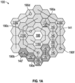
- a panel 100 has first and second layers 110, 130 each having first and second opposed major surfaces, 111, 112, 131, 132 and a core 120 disposed there between.
- the second layer 130 is free of any openings between the first and second major surfaces 131, 132 of the second layer 130.
- the core 120 has plurality of walls 141 extending from second surface 112 of first layer 110 to first surface 131 of second layer 130 providing first series 160, 160' of connected cells 140, 140'.
- second and third series of cells 1160, 1160', and 2160, 2160' are also shown.
- Some of the cell walls 141a, 141b, 141c have openings 150 providing fluid communication between the first series 160 of five cells 140.
- Each cell wall 141 has a plurality of sides 171, 172.
- Each side 171, 172 of the cell wall 141 has an area A.
- the opening 150 in the cell wall 141a has area A' that is at least 50 percent of area A.
- the first layer 110 has at least a first opening 190a, 190b extending between the first and second major surfaces 111, 112 of the first layer 110 into at least one cell in series 160, 160'.
- openings 190a, 190b, 190c, etc. displayed as circles, but can be any of a variety of shapes including squares, triangles, rectangles, hexagons, or other polygons. Multiple openings could also be used, including openings having at least two holes, or openings which include a woven or non-woven permeable material. In some embodiments, at least 50 (in some embodiments, at least 55, 60, 65, 70, 75, 80, 85, 90, 95, or even at least 100) percent of the openings 150 in a cell wall 141 emanate from either the first layer 110 or the second layer 130. Referring to FIGS.
- the opening 150 can have contours having curved and straight portions, and any straight portions can be either perpendicular to or tilted at another angle to the layers 110 and 130.
- the center cell 188 could have an opening in the first layer 110.
- each cell has at least 3 (in some embodiments, at least 4, 5, 6, 7, 8, 9, or even at least 10) walls.
- a method of making an article comprises:
- an article made by the method according to the first aspect.
- another article comprises at least one molded structure disposed on a surface of a panel, having a material-to-material connection between the surface of the panel and the molded structure, wherein the molded structure comprises a foam composition, wherein the panel comprises first and second layers each having first and second opposed major surfaces and a core disposed there between, the second layer being free of any openings between the first and second major surfaces of the second layer, wherein the core has a plurality of walls extending from the second surface of the first layer to the first surface of the second layer providing a series of connected cells, wherein some of the cell walls have openings providing fluid communication between a series of at least 3 cells, wherein each cell wall has a plurality of sides, wherein each side of a cell wall has an area, and wherein the opening in a cell wall has an area that is at least 50 percent of the area of a side of that cell wall, and wherein the first layer has
- the disclosure below relates to each of the first, second, and third aspects.
- Molded structures can be applied to any portion of a panel, such as on at least one major surface of the panel, an edge of the panel, or a shaped part of the panel. Additionally, at least one profile element may be molded directly onto the mold structure, on an edge side of the panel, or both.
- Suitable curable compositions include at least one blowing agent and at least one of a polyethylene, a polypropylene, a polyolefin, a polyvinylchloride, a polyurethane, a polyester, a polyamide, a polystyrene, a polyisocyanurate, a silicone, or a copolymer thereof.
- the composition can further comprise at least one filler, such as beads, bubbles, fibers, carbon black, a mineral, a fire retardant (described in detail below), or other particles (e.g., macroparticles, microparticles, nanoparticles, nonporous particles, and/or porous particles (such as the porous carbon particles described in co-owned application WO 2019/079695 (Lee et al. )).
- at least one filler such as beads, bubbles, fibers, carbon black, a mineral, a fire retardant (described in detail below), or other particles (e.g., macroparticles, microparticles, nanoparticles, nonporous particles, and/or porous particles (such as the porous carbon particles described in co-owned application WO 2019/079695 (Lee et al. )).
- a suitable curable composition comprises Tufcote Acoustical Foam (commercially available from Aearo Technologies, LLC, Indianapolis, IN), which is reported to be based on a toluene diisocyanate (TDI) pre-polymer formed from TDI and a polyether polyol having a molecular weight of 4,800 grams per mole.
- Additives in the composition include silicone surfactant as a cell stabilizer, amine catalyst, a black pigment dispersion, and a chlorinated phosphate flame retardant.
- Foam cells are provided by water reacting with the TDI to form carbon dioxide, which foams the composition as it cures.
- the blowing agent can be at least one of a chemical blowing agent, a physical blowing agent, or expandable microspheres.
- Physical blowing agents such as volatile liquid and gas blowing agents, expand when heated and then tend to escape from the mixture, leaving voids behind, to form the foam composition.
- Suitable physical blowing agents include for instance and without limitation, water, nitrogen, or carbon dioxide.
- Chemical blowing agents (CBAs) decompose and at least a portion of the decomposition product(s) expand and then escape from the mixture, leaving voids behind.
- Suitable chemical compound blowing agents include for instance and without limitation, a diazocompound, a sulfonyl hydrazide, a tetrazole, a nitrosocompound, an acyl sulfonyl hydrazide, hydrazones, thiatriazoles, azides, sulfonyl azides, oxalates, thiatrizine dioxides, isotaoic anhydride, or any combination thereof.
- Expandable microspheres are composed of gas or liquid hydrocarbon PBAs inside a polymer shell. When heated past the glass transition temperature (T g ) of the shell, the shell becomes malleable and expands due to the internal pressure of the heated PBA inside.
- T g glass transition temperature
- the thickness of the shell and the quantity of PBA encapsulated is tuned to enable isotropic expansion rather than shell rupture, leading to an increase in volume. This process leads to a syntactic foam filled with polymer shells, generally with
- a portion of a panel 210 is clamped in a clamp frame 212 and placed in an injection molding die 220, e.g., between a first injection mold half 220a and a second injection mold half 220b.
- an injection molding die 220 e.g., between a first injection mold half 220a and a second injection mold half 220b.
- the entire panel 210 is inserted into the injection molding die 220.
- the two halves 220a and 220b of the injection molding die 220 are then closed, and the panel 210 conforms to the shape between the first half 220a and the second half 220b of the injection molding die 220.
- the panel 210 may comprise a shape (e.g., flat) and the shape of the panel 210 is altered inside the injection molding die 220.
- a portion 215 of the panel 210 is consolidated by the compression of the injection molding die 220.
- at least one cell of the panel is consolidated and folded over to form a reinforcement bead.
- the injection molding die is configured to reduce a thickness of at least a portion of the panel or of the entire panel by 5% to 95% or increase a thickness of at least a portion of the panel or of the entire panel by 5% to 50%.
- the injection molding die may be shaped to reduce the thickness of a portion or all of a panel by 5% or more, 10% or more, 15% or more, 20% or more, 25% or more, 30% or more, 35% or more, 40% or more, 45% or more, 50% or more, 55% or more, or even 60% or more; and 95% or less, 90% or less, 85% or less, 80% or less, 75% or less, 70% or less, or 65% or less.
- the decrease in thickness is a decrease in the thickness of the core of the panel.
- the injection molding die may be shaped to increase the thickness of a portion or all of a panel by 5% or more, 10% or more, 15% or more, 20% or more, 25% or more, or even 30% or more; and 50% or less, 45% or less, 40% or less, or 35% or less.
- Increasing the thickness of a panel may involve pulling a vacuum in the injection molding die to draw out the panel material.
- the two halves 220a and 220b of the injection molding die 220 are configured to leave vacant cavity space 240 between at least a portion of the panel 210 and the second half 220b of the injection molding die 220.
- the panel is supported in the injection molding die on at least a portion of a first layer of the panel.
- the panel is supported in the injection molding die on each of the first layer and the second layer of the panel.
- the panel is unsupported in the injection molding die on each of the first layer and the second layer. The locations of support (if any) will be determined by the design of the final product, in particular where overmolding structure is to be formed on the panel.
- the method further comprises overmolding at least one molded structure 250 on a surface 211 of the panel 210 in the injection molding die 220, thereby forming a material-to-material connection 255 between the surface 211 of the panel 210 and the molded structure 250.
- material-to-material connection refers to the material of a surface of a panel directly contacting the material of a molded structure, with the exception of at most two intermediate layers, preferably one intermediate layer (or no intermediate layer), such as a primer layer and/or a tie layer that assists to adhere the two materials together optionally being present on at least a portion of the material of the surface of the panel.
- an overmolding material 232 is injected through an injection port 230 into the vacant cavity 240.
- the molded structure 250 is applied to at least one major surface 211 of the panel 210.
- the molded structure may be formed by providing a curable composition comprising a blowing agent into a vacant cavity in the injection molding die and curing the curable composition to form the foam composition.
- the injection molding die is configured to increase a thickness of at least a portion of the panel or of the entire panel by 5% to 1,000% due to the overmolding in a vacant cavity of the injection molding die.
- the injection molding die may be shaped to increase the thickness of a portion or all of a panel, due to the presence of an overmolded structure adding to the overall thickness, by 5% or more, 25% or more, 50% or more, 75% or more, 100% or more, 200% or more, 300% or more, 400% or more, or even 500% or more; and 1,000% or less, 900% or less, 800% or less, 700% or less, or 600% or less.
- an overmolded structure that comprises a foam provides a wide range of thicknesses of the structure.
- the flexibility in design of the overmolded structure allows for the article to fit a variety of desired shapes and thicknesses for a particular purpose, e.g., including filling up space in need of acoustic absorption that might otherwise require three, four, five, or more stacked acoustic panels to fill.
- the molded structure comprises a thickness of 0.1 mm or greater, 0.25 mm or greater, 0.5 mm or greater, 1 mm or greater, 2 mm or greater, 3 mm or greater, 5 mm or greater, 7 mm or greater, 10 mm or greater, 12 mm or greater, 15 mm or greater, 17 mm or greater, 20 mm or greater, or 25 mm or greater; and a thickness of 76 mm or less, 70 mm or less, 65 mm or less, 60 mm or less, 55 mm or less, 50 mm or less, 45 mm or less, 40 mm or less, 35 mm or less, or 30 mm or less.
- the molded structure may comprise a thickness of 0.1 millimeters (mm) to 76 mm.
- the molded structure optionally comprises a closed cell foam, an open cell foam, or a combination of both closed cell foam and open cell foam.
- an open cell foam means that the foam contains connected cell pathways that extend from one outer surface through the material to another outer surface.
- a closed cell foam means that the foam contains substantially no connected cell pathways that extend from one outer surface through the material to another outer surface.
- a closed cell foam can include up to about 10% open cells, within the meaning of "substantially" no connected cell pathways.
- the foam composition comprises 90% or greater closed cells, 92% or greater closed cells, 95% or greater closed cells, or 98% or greater closed cells. Achieving a particular cell type (i.e., open and/or closed) depends on the specific blowing agent and curing conditions of the curable composition.
- the molded structure comprises a material exhibiting a hardness of 10 Shore OO or greater, 20 Shore OO or greater, 30 Shore OO or greater, 40 Shore OO or greater, 50 Shore OO or greater, 60 Shore OO or greater, 70 Shore OO or greater, 80 Shore OO or greater, or 90 Shore OO or greater; and a hardness of 90 Shore D or less, 80 Shore D or less, 70 Shore D or less, 60 Shore D or less, 50 Shore D or less, 40 Shore D or less, 30 Shore D or less, 20 Shore D or less, or 10 Shore D or less.
- the molded structure may comprise a material exhibiting a hardness of 10 Shore OO to 90 Shore D, 10 Shore OO to 70 Shore OO, 80 Shore OO to 30 Shore D, or 10 Shore D to 90 Shore D.
- a porous layer such as the molded structure can be generally characterized by its specific acoustic impedance, which is the ratio in frequency space of acoustic pressure to the associated particle speed in an acoustic medium.
- specific acoustic impedance is the ratio in frequency space of acoustic pressure to the associated particle speed in an acoustic medium.
- the velocity derives from air moving into and out of the holes. If the film is flexible, motion of the wall can contribute to the acoustic impedance calculation.
- Specific acoustic impedance varies as a function of frequency and is generally a real quantity in progressive plane wave condition, however, the specific acoustic impedance becomes a complex number under the standing plane wave or diverging wave conditions.
- the specific impedance of an acoustic medium reflects the fact that pressure and velocity waves can create phase mismatch between the two properties and this phase mismatch behavior reflects the acoustic absorption performance.
- the flow resistance is the low frequency limit of the transfer impedance. Experimentally, this can be estimated by blowing a known, small velocity of air at the molded structure and measuring the pressure drop associated therewith. The flow resistance can be determined as the measured pressure drop divided by the velocity.
- specific acoustic impedance is measured in units of Pa ⁇ s/m 2 , which is equivalent to MKS Rayl/m.
- the molded structure exhibits an airflow resistance of 4,000 Pa ⁇ s/m 2 or greater, 6,000 Pa ⁇ s/m 2 or greater, 10,000 Pa ⁇ s/m 2 or greater, 15,000 Pa ⁇ s/m 2 or greater, 20,000 Pa ⁇ s/m 2 or greater, 25,000 Pa ⁇ s/m 2 or greater, 30,000 Pa ⁇ s/m 2 or greater, 35,000 Pa ⁇ s/m 2 or greater, or 40,000 Pa ⁇ s/m 2 or greater; and an airflow resistance of 70,000 Pa ⁇ s/m 2 or less, 65,000 Pa ⁇ s/m 2 or less, 60,000 Pa ⁇ s/m 2 or less, 55,000 Pa ⁇ s/m 2 or less, 50,000 Pa ⁇ s/m 2 or less, 45,000 Pa ⁇ s/m 2 or less. Stated another way, the molded structure exhibits an airflow resistance of 4,000 to 70,000 Pa ⁇ s/m 2 .
- an acoustical panel 210 is optionally preheated outside of the injection mold, e.g., using an infrared heater 260.
- Closing of the injection mold die 220 shapes the preheated panel 210 as described below in Example 1, such that the overmolding of a foam composition on the shaped panel occurs in a single machine.
- the method further comprises cooling the shaped panel prior to overmolding the molded structure on a surface of the panel, such as by exposure to ambient air or circulating a cooling fluid through the injection mold die.
- thermoforming includes heating the panel and applying force to shape the panel against at least one tool.
- the panel is heated to a processing temperature where it becomes compliant.
- the panel can be heated to a softening temperature of the first layer, the second layer, or both, of the panel.
- the panel is then positioned within a mold, between 2 platens prior to the platens closing.
- the panel is shaped by mechanical force from the tool, or by vacuum or pneumatic pressure followed by a cooling period to return the panel to a rigid structure.
- Polypropylene (PP) panels can be thermoformed, for example, with the panel pre-heat temperature of 310-350°F (154-177 °C), mold temperature of 150°F (66°C), clamping force of 4,000 lbs. (1,814 kgf) and cooling time of 30 seconds.
- a portion of a panel 310 is clamped in a clamp frame 312 and placed in a thermoforming machine 370, e.g., between a first thermoforming tool half 370a and a second thermoforming tool half 370b.
- the panel 310 is optionally preheated outside of the thermoforming machine, e.g., using an infrared heater 360, as shown in FIG. 3A .
- the entire panel 310 is inserted into the thermoforming machine 370.
- thermoforming machine 370 The two tool halves 370a and 370b of the thermoforming machine 370 are then closed, and the panel 310 conforms to the shape between the first half 370a and the second half 370b of the thermoforming machine 370. As shown in FIG. 3C , a portion 315 of the panel 310 is consolidated by the compression of the thermoforming machine 370.
- the pre-formed panel 310 is removed from the thermoforming machine.
- the pre-formed panel 310 is inserted between two halves 320a and 320b of an injection molding die 320, which are configured to provide a vacant cavity space 340 between at least a portion of the panel 310 and the second half 320b.
- the method further comprises overmolding at least one molded structure 350 on a surface 311 of the panel 310 in the injection molding die 320, thereby forming a material-to-material connection 355 between the surface 311 of the panel 310 and the molded structure 350.
- an overmolding material 332 is injected through an injection port 330 into the vacant cavity 340, thereby forming the article.
- the molded structure 350 is applied to at least one major surface 311 of the panel 310.
- methods for making articles from panels can comprise shaping a panel described herein via insert molding to provide the article.
- the mold closing action forms the panel into a three-dimensional shape while the overmolded structure comprising foam provides additional acoustic absorption of the final article.
- the mold closing force may be enough to shape the panel, or thermoforming/compression molding performed prior to insert molding may be required; in either case, pre-heating the formed panel may not be necessary.
- the panel is perforated by the injection mold.
- a panel undergoing overmolding may be flat or alternatively comprise a (e.g., three-dimensional) shape.
- the method may further comprise altering the shape of the panel (e.g., "reshaping" the panel) in the injection molding die.
- at least one cell is consolidated and folded over to form a reinforcement bead.
- a number of adjacent cells are consolidated and folded over they can form a "hem" having a thickness approximately equal to twice the thickness of the first and second layers of the panel.
- Suitable methods optionally further comprise at least partially shaping a (flat) panel using thermoforming or compression molding prior to placing at least a portion of the panel within the injection molding die, e.g., using vacuum, pressure, or matched mold forming to shape the panel.
- Materials used in matched mold forming are not particularly limited, and include for instance and without limitation, metal, plywood, or epoxy board (e.g., available under the trade designation "RENSHAPE", from OBO-Werke GmbH, Stadthagen, Germany).
- RENSHAPE available under the trade designation
- putting a panel inside of a mold between 2 platens, heating the mold, closing the platens to shape the panel while maintaining pressure during a mold cooling stage provides the article.
- the panel must be pre-heated prior to closing the mold to ensure material compliance.
- Exemplary polypropylene (PP) panels can be compression molded, for example, without panel pre-heating, thermal cycling mold temperatures of 305°F (152°C) and 150°F (66°C), clamping force of 30,000 lbs. (13,607 kgf) and cooling/pressure holding time of 30 seconds.
- the first layer of the panel comprises at least one opening between the first and second major surfaces of the first layer
- the method further comprises plugging the at least one opening prior to overmolding the at least one molded structure on a surface of the panel in the injection molding die.
- An opening may be plugged by a pin selected to have a diameter large enough to fit in the opening but minimize entry of curable composition into the opening during the overmolding process.
- panels have a thickness of 4 millimeters (mm) or greater, 6 mm or greater, 8 mm or greater, 10 mm or greater, 12 mm or greater, 14 mm or greater, or 16 mm or greater; and a thickness of 25 mm or less, 23 mm or less, 21 mm or less, 19 mm or less, 17 mm or less, 15 mm or less, 14 mm or less, 12 mm or less, 10 mm or less, or 8 mm or less.
- panels may have a thickness in a range from 4 mm to 8 mm, 6 mm to 10 mm, 8 mm to 15 mm, or 4 mm to 25 mm.
- each cell of a panel has a largest distance between two opposed walls of at least 3 mm (in some embodiments, at least 5 mm, 10 mm, 15 mm, 20 mm, 25 mm, or even at least 30 mm; in some embodiments, in a range from 3 mm to 30 mm, 7 mm to 30 mm, 15 mm to 30 mm, or even 20 mm to 30 mm).
- each cell has a largest distance between two opposed vertices of at least 5 mm (in some embodiments, at least 10 mm, 15 mm, 20 mm, 25 mm, 30 mm, 35 mm, or even at least 40 mm; in some embodiments, in a range from 15 mm to 40 mm, 20 mm to 40 mm, or even 30 mm to 40 mm).
- each cell of a panel has a distance from the second surface of the first layer to the first surface of the second layer of at least 2 mm (in some embodiments, at least 3 mm, 4 mm, 5 mm, 6 mm, 7 mm, 8 mm, 9 mm, 10 mm, or even at least 15 mm; in some embodiments, in a range from 4 mm to 15 mm, 7 mm to 15 mm, or even 10 mm to 15 mm).
- each cell has a volume of at least 0.04 cm 3 (in some embodiments, at least 0.1 cm 3 , 0.5 cm 3 , 1 cm 3 , 2 cm 3 , 3 cm 3 , 4 cm 3 , 5 cm 3 , 10 cm 3 , 15 cm 3 , 20 cm 3 , 25 cm 3 , or even at least 30 cm 3 ; in some embodiments, in a range from 0.04 cm 3 to 30 cm 3 , 0.1 cm 3 to 30 cm 3 , 0.5 cm 3 to 30 cm 3 , 2 cm 3 to 30 cm 3 , or even 15 cm 3 to 30 cm 3 ).
- a series of cells has a cumulative volume of at least 0.5 cm 3 (in some embodiments, at least 1 cm 3 , 1.5 cm 3 , 2 cm 3 , 3 cm 3 , 4 cm 3 , 5 cm 3 , 10 cm 3 , 25 cm 3 , 50 cm 3 , 75 cm 3 , 100 cm 3 , 150 cm 3 , or even at least 200 cm 3 ; in some embodiments, in a range from 1.5 cm 3 to 200 cm 3 , 10 cm 3 to 120 cm 3 , or even 50 cm 3 to 200 cm 3 ).
- a first series of cells comprises at least 4 (in some embodiments, at least 5, 6, 7, 8, 9, 10, 11, 12, 13, 14, 15, 16, 17, 18, 19, 20, 21, 22, 23, 24, 25, 26, 27, 28, 29, 30 or more) cells.
- panels further comprise a second series of at least 3 (in some embodiments, at least 4, 5, 6, 7, 8, 9, 10, 11, 12, 13, 14, 15, 16, 17, 18, 19, 20, 21, 22, 23, 24, 25, 26, 27, 28, 29, 30 or more) cells.
- panels further comprise a third series of at least 3 (in some embodiments, at least 4, 5, 6, 7, 8, 9, 10, 11, 12, 13, 14, 15, 16, 17, 18, 19, 20, 21, 22, 23, 24, 25, 26, 27, 28, 29, 30 or more) cells.
- a series of cells has a cumulative length of at least 20 mm (in some embodiments, at least 30 mm, 40 mm, 50 mm, 75 mm, 100 mm, 150 mm, or even at least 200 mm; in some embodiments, in a range from 30 mm to 200 mm, 50 mm to 200 mm, or even 100 mm to 200 mm).
- the first layer comprises at least one of polymeric, metallic, ceramic, or composite materials (e.g., fiber reinforced, woven or non-woven in a resin matrix).
- the second layer comprises at least one of polymeric, metallic, ceramic, or composite materials (e.g., fiber reinforced, woven or non-woven in a resin matrix).
- the core comprises at least one of polymeric, metallic, ceramic, or composite materials (e.g., fiber reinforced, woven or non-woven in a resin matrix).
- Exemplary polymeric materials include polyethylenes, polypropylenes, polyolefins, polyvinylchlorides, polyurethanes, polyesters, polyamides, polystyrene, copolymers thereof, and combinations thereof (including blends).
- the polymeric materials may be thermosetting by, for example, heat or ultraviolet (UV) radiation, or thermoplastic.
- the molded structure and the panel comprise the same type(s) of polymer.
- Exemplary metallic materials include aluminum, steel, nickel, copper, brass, bronze, and alloys thereof.
- Exemplary ceramic (including glass, glass-ceramic, and crystalline ceramic) materials include oxides, nitrides, and carbides.
- Exemplary fiber containing materials include fibers such as cellulose, carbon, thermoplastic fibers (polyamide, polyester, and aramid, polyolefin), steel, and glass, as may be applicable to the particular type of material.
- materials for panels may be in the form of multilayers.
- materials for panels may also include fillers, colorants, plasticizers, dyes, etc., as may be applicable to the particular type of material.
- panels further comprise a tie layer on at least a portion of the second of the major surface of the first layer.
- panels described herein further comprising a tie layer on at least a portion of the first of the major surface of the second layer.
- the tie layer is believed to facilitate adhesion between first or second layer 110, 130 and core layer 120.
- a panel may be surface treated, such as by treating a surface of the panel to increase adhesion of the molded structure to the panel.
- the surface on which a curable composition is to be molded can be treated to improve adhesion between the panel surface and the molded structure using typical treatment methods, e.g., chemical treatment (e.g., primer layer), corona treatment such as air or nitrogen corona, plasma, flame, or actinic radiation.
- methods further comprise disposing a substrate facing into an injection molding die at a distance from the panel and attaching the substrate to the molded structure when the foam composition forms, such that the molded structure is disposed between the panel and the substrate in the final article.
- Suitable substrates include for instance, a polymeric film, a woven material, a nonwoven material (e.g., a microperforated film), or a combination thereof.
- the substrate can provide acoustic properties to the final article.
- the substrate may provide a function such as in-mold labelling or further tuning acoustic properties of the foam composition.
- articles described herein exhibit at least one absorption band less than 1400 Hz (in some embodiments, less than 1300 Hz, or even less than 1200 Hz). In some embodiments, articles described herein exhibit at least one absorption band in a range from at least 400 Hz to 1200 Hz (in some embodiments, in a range from at least 500 Hz to 1300 Hz, at least 200 Hz to 1400 Hz, at least 100 Hz to 1400 Hz, or even at least 20 Hz to 1400 Hz).
- the molded structure itself may exhibit at least one absorption band in a range from 100 Hz to 800 Hz, such as 200 Hz to 800 Hz, 300 Hz to 800 Hz, 400 Hz to 800 Hz, 500 Hz to 800 Hz, or 600 Hz to 800 Hz.
- articles described herein exhibit an acoustical absorption of at least 50 (in some embodiments, at least 55, 60, 65, 70, 75, or even 80) percent.
- the absorption bands of articles and the acoustical absorption of panels are measured as described in the Examples using the "Normal Incidence Acoustical Absorption Test" and the "Reverberation Chamber Test.”
- the frequency of the peak absorption decreases; 2) as the skin hole size (whether provided by one hole or multiple holes) increases, the frequency of the peak absorption increases; 3) as the width of the cell decreases, more cells need to be connected to exhibit absorption at the same frequency; 4) as the cell height decreases, the frequency of the peak absorption increases; 5) as the passageway size decreases, the frequency of the peak absorption decreases (plus with less total absorption and narrower absorption peaks); and 6) as the skin thickness increases, the frequency of peak absorption decreases.
- multiple variables can be adjusted to optimize (e.g., tune) the acoustic absorption of a panel or article for a particular end use application.
- Exemplary embodiments can be formed articles such as automotive parts, such as engine covers, wheel well liners, underbody shields, headliners, trunk covers, floor mats, carpet backings, hood liners, and tonneau covers, housings for generators, motors, appliances, tools, etc., and in general, any item emitting sound; architectural walls, panels, floors, doors, enclosures, ducts, sound barriers, etc., aircraft, watercraft, trucks, trains, agricultural equipment, fork lifts, and trailers.
- automotive parts such as engine covers, wheel well liners, underbody shields, headliners, trunk covers, floor mats, carpet backings, hood liners, and tonneau covers, housings for generators, motors, appliances, tools, etc., and in general, any item emitting sound; architectural walls, panels, floors, doors, enclosures, ducts, sound barriers, etc., aircraft, watercraft, trucks, trains, agricultural equipment, fork lifts, and trailers.
- Suitable polymers include for instance and without limitation, polyamides including PA6, PA66, polybutylene terephthalate (PBT), poly ethylene terephthalate (PET), poly ethylene naphthalate (PEN), polyphenylene sulfide (PPS), Polyether imide (PEI), Polyether sulfone (PES), Polyether ketone (PEK) and Polyether ether ketone (PEEK) and fluoropolymers.
- polyamides including PA6, PA66, polybutylene terephthalate (PBT), poly ethylene terephthalate (PET), poly ethylene naphthalate (PEN), polyphenylene sulfide (PPS), Polyether imide (PEI), Polyether sulfone (PES), Polyether ketone (PEK) and Polyether ether ketone (PEEK) and fluoropolymers.
- additives such as flame retardants are typically added to heat resistant polymeric materials to provide further protection during high temperature applications.
- Useful flame retardants include for instance and without limitation, inorganics such as alumina trihydrate (ATH), huntite and hydromagnesite, various hydrates, phosphorus, boron compounds, antimony trioxide and pentoxide and sodium antimonate; halogenated compounds such as organochlorines including chlorendic acid derivatives and chlorinated paraffins; organobromines such as decabromodiphenyl ether (decaBDE), decabromodiphenyl ethane, polymeric brominated compounds, brominated carbonate oligomers (BCOs), brominated epoxy oligomers (BEOs), tetrabromophthalic anyhydride, tetrabromobisphenol A (TBBPA) and hexabromocyclododecane (HBCD); organophosphates such as triphenyl phosphate (TPP),
- the acoustical spectrum of an engine depends on many factors including engine design, load and rotations per minute (rpm).
- the articles of the present disclosure may thus need to be tuned to several prominent frequencies.
- the panel is quickly transferred between the injection mold halves of an injection molding machine (e.g., Engel 100TL, ENGEL AUSTRIA GmbH, Schwertberg, Austria) and the mold closing sequence is initiated, subsequently forming the panel until the mold is fully clamped.
- an injection molding machine e.g., Engel 100TL, ENGEL AUSTRIA GmbH, Schwertberg, Austria
- the mold closing sequence is initiated, subsequently forming the panel until the mold is fully clamped.
- the acoustic panel may be fully supported on both sides, it may be only supported on one side, it is possible to be unsupported on both sides or it is able to be consolidated to a thickness below 8 mm and potentially perforated by the injection mold steel.
- the injection molding machine's injection unit actuates, providing an open or closed cell foam overmolding material into the vacant cavity regions or space where the acoustic panel is unsupported.
- thermoforming machine e.g., MAAC C5535SPT, MAAC MACHINERY, Carol Stream, IL.
- the thermoforming machine positions the panel within an IR heating oven and holds the panel until a critical softening temperature of the panel skin is reached (e.g., approximately 150-165°C).
- the panel is quickly transferred between the thermoforming tool halves and the tool closing sequence is initiated, subsequently forming the panel until the mold is fully clamped at which point air pressure or vacuum may be applied to further shape the panel. After a cooling duration, the tool is opened and the formed panel is removed from clamp frame.
- the pre-formed panel is loaded within the injection mold of an injection molding machine (e.g., Engel 100TL) and the mold is closed fully.
- the injection molding machine's injection unit actuates, providing an open or closed cell foam overmolding material into the vacant cavity regions or space where the acoustic panel is unsupported.
Landscapes
- Engineering & Computer Science (AREA)
- Physics & Mathematics (AREA)
- Acoustics & Sound (AREA)
- Multimedia (AREA)
- Manufacturing & Machinery (AREA)
- Mechanical Engineering (AREA)
- Moulds For Moulding Plastics Or The Like (AREA)
- Injection Moulding Of Plastics Or The Like (AREA)
Claims (15)
- Ein Verfahren zum Herstellen eines Gegenstands, das Verfahren aufweisend:Platzieren mindestens eines Abschnitts einer Platte in einer Spritzgussform; undUmspritzen mindestens einer gegossenen Struktur auf einer Oberfläche der Platte in der Spritzgussform, wodurch eine stoffschlüssige Verbindung zwischen der Oberfläche der Platte und der gegossenen Struktur ausgebildet wird, wobei die gegossene Struktur eine Schaumzusammensetzung aufweist,wobei die Platte eine erste und eine zweite Schicht aufweist, die jeweils eine erste und eine zweite Hauptoberfläche und einen dazwischen angeordneten Kern umfassen, wobei die zweite Schicht frei von beliebigen Öffnungen zwischen der ersten und der zweiten Hauptoberfläche der zweiten Schicht ist, wobei der Kern eine Mehrzahl von Wänden umfasst, die sich von der zweiten Oberfläche der ersten Schicht zu der ersten Oberfläche der zweiten Schicht erstrecken und eine Reihe von verbundenen Zellen bereitstellen, wobei einige der Zellwände Öffnungen umfassen, die zwischen einer Reihe von mindestens 3 Zellen eine Fluidverbindung bereitstellen, wobei jede Zellwand eine Mehrzahl von Seiten umfasst, wobei jede Seite einer Zellwand eine Fläche umfasst, und wobei die Öffnung in einer Zellwand eine Fläche umfasst, die mindestens 50 Prozent der Fläche einer Seite dieser Zellwand ist, und wobei die erste Schicht mindestens eine Öffnung umfasst, die sich zwischen der ersten und der zweiten Hauptfläche der ersten Schicht in mindestens eine Zelle in der Reihe erstreckt.
- Das Verfahren nach Anspruch 1, wobei die gegossene Struktur ein Polyethylen, ein Polypropylen, ein Polyolefin, ein Polyvinylchlorid, ein Polyurethan, einen Polyester, ein Polyamid, ein Polystyrol, ein Polyisocyanurat, ein Silikon oder ein Copolymer davon aufweist.
- Das Verfahren nach Anspruch 1 oder 2, ferner aufweisend ein Vorwärmen der Platte auf eine Erweichungstemperatur der ersten Schicht der Platte vor einem Platzieren davon innerhalb der Spritzgussform.
- Das Verfahren nach einem der Ansprüche 1 bis 3, wobei die Platte in der Spritzgussform auf mindestens einem Anschnitt der ersten Schicht gestützt wird.
- Das Verfahren nach einem der Ansprüche 1 bis 3, wobei die Platte in der Spritzgussform auf jeder der ersten und der zweiten Schicht nicht gestützt wird.
- Das Verfahren nach einem der Ansprüche 1 bis 5, wobei die gegossene Struktur auf mindestens eine Hauptoberfläche der Platte aufgebracht wird.
- Das Verfahren nach einem der Ansprüche 1 bis 6, wobei die gesamte Platte in die Spritzgussform eingelegt wird.
- Das Verfahren nach einem der Ansprüche 1 bis 7, wobei die Platte eine Gestalt aufweist und das Verfahren ferner ein Ändern der Gestalt der Platte in der Spritzgussform aufweist.
- Das Verfahren nach einem der Ansprüche 1 bis 8, wobei mindestens eine Zelle verfestigt und umgefaltet wird, um eine Verstärkungswulst auszubilden.
- Das Verfahren nach einem der Ansprüche 1 bis 9, wobei die Spritzgussform konfiguriert ist, um eine Dicke von mindestens einem Abschnitt der Platte um 5 % bis 95 % zu reduzieren oder eine Dicke von mindestens einem Abschnitt der Platte um 5 % bis 1.000 % zu erhöhen.
- Das Verfahren nach einem der Ansprüche 1 bis 10, ferner aufweisend mindestens teilweises Gestalten der Platte unter Verwendung von Thermoformen oder Druckpressen vor einem Platzieren mindestens eines Teils der Platte innerhalb der Spritzgussform.
- Das Verfahren nach einem der Ansprüche 1 bis 11, wobei die gegossene Struktur durch ein Bereitstellen einer härtbaren Zusammensetzung, aufweisend ein Treibmittel, in einen freien Hohlraum in den Spritzgussformen und ein Aushärten der härtbaren Zusammensetzung ausgebildet wird, um die Schaumzusammensetzung auszubilden.
- Das Verfahren nach einem der Ansprüche 1 bis 12, wobei die erste Schicht der Platte mindestens eine Öffnung zwischen der ersten und der zweiten Hauptoberfläche der ersten Schicht aufweist, und wobei das Verfahren ferner ein Verschließen der mindestens einen Öffnung vor dem Umspritzen der mindestens einen gegossenen Struktur auf einer Oberfläche der Platte in der Spritzgussform aufweist.
- Das Verfahren nach einem der Ansprüche 1 bis 13, ferner aufweisend das Anordnen eines Substrats in Richtung der Spritzgussform gewandt und in einem Abstand von der Platte und ein Befestigen des Substrats an der gegossenen Struktur bei dem Ausbilden der Schaumzusammensetzung, wobei die gegossene Struktur zwischen der Platte und dem Substrat angeordnet ist.
- Ein Gegenstand, aufweisend mindestens eine gegossene Struktur, die auf einer Oberfläche einer Platte angeordnet ist, die zwischen der Oberfläche der Platte und der gegossenen Struktur eine Material-zu-Material-Verbindung umfasst, wobei die gegossene Struktur eine Schaumzusammensetzung aufweist,
wobei die Platte eine erste und eine zweite Schicht aufweist, die jeweils eine erste und eine zweite Hauptoberfläche und einen dazwischen angeordneten Kern umfassen, wobei die zweite Schicht frei von beliebigen Öffnungen zwischen der ersten und der zweiten Hauptoberfläche der zweiten Schicht ist, wobei der Kern eine Mehrzahl von Wänden umfasst, die sich von der zweiten Oberfläche der ersten Schicht zu der ersten Oberfläche der zweiten Schicht erstrecken und eine Reihe von verbundenen Zellen bereitstellen, wobei einige der Zellwände Öffnungen umfassen, die zwischen einer Reihe von mindestens 3 Zellen eine Fluidverbindung bereitstellen, wobei jede Zellwand eine Mehrzahl von Seiten umfasst, wobei jede Seite einer Zellwand eine Fläche umfasst, und wobei die Öffnung in einer Zellwand eine Fläche umfasst, die mindestens 50 Prozent der Fläche einer Seite dieser Zellwand ist, und wobei die erste Schicht mindestens eine Öffnung umfasst, die sich zwischen der ersten und der zweiten Hauptfläche der ersten Schicht in mindestens eine Zelle in der Reihe erstreckt.
Applications Claiming Priority (2)
| Application Number | Priority Date | Filing Date | Title |
|---|---|---|---|
| US201962904132P | 2019-09-23 | 2019-09-23 | |
| PCT/IB2020/058635 WO2021059088A1 (en) | 2019-09-23 | 2020-09-16 | Articles including panels and molded structures and methods of making same |
Publications (2)
| Publication Number | Publication Date |
|---|---|
| EP4034362A1 EP4034362A1 (de) | 2022-08-03 |
| EP4034362B1 true EP4034362B1 (de) | 2024-10-30 |
Family
ID=72644513
Family Applications (1)
| Application Number | Title | Priority Date | Filing Date |
|---|---|---|---|
| EP20780355.2A Active EP4034362B1 (de) | 2019-09-23 | 2020-09-16 | Gegenstände, die platten und geformte strukturen einschliessen, und verfahren zu deren herstellung |
Country Status (3)
| Country | Link |
|---|---|
| US (1) | US20220242018A1 (de) |
| EP (1) | EP4034362B1 (de) |
| WO (1) | WO2021059088A1 (de) |
Families Citing this family (2)
| Publication number | Priority date | Publication date | Assignee | Title |
|---|---|---|---|---|
| FR3123755B1 (fr) * | 2021-06-08 | 2024-02-23 | Safran | Dispositif de traitement acoustique pour ensemble propulsif d’aeronef et son procede de fabrication |
| JP2026002723A (ja) * | 2024-06-20 | 2026-01-08 | オトラジェット インコーポレイテッド | 成形装置及び成形方法 |
Family Cites Families (10)
| Publication number | Priority date | Publication date | Assignee | Title |
|---|---|---|---|---|
| DE2114181A1 (de) * | 1971-03-24 | 1972-10-12 | Opel Adam Ag | Verfahren zur Herstellung von Verkleidungsteilen fuer Fahrzeuge |
| US3963094A (en) * | 1974-07-11 | 1976-06-15 | Donley, Miller & Nowikas, Inc. | Muffler structures |
| SE500725C2 (sv) * | 1992-12-29 | 1994-08-15 | Volvo Ab | Anordning vid paneler för farkoster |
| US5897818A (en) * | 1994-01-14 | 1999-04-27 | Compsys, Inc. | Method for continuously manufacturing a composite preform |
| DE10059762A1 (de) * | 2000-11-30 | 2002-06-06 | Magna Eybl Systemtechnik Gmbh | Verbundteil und Verfahren zu dessen Herstellung |
| EP1857247A1 (de) * | 2006-05-18 | 2007-11-21 | Recticel | Verfahren zur Herstellung eines merhschichtigen Teils |
| DE102014208421B4 (de) * | 2014-05-06 | 2024-10-02 | Volkswagen Aktiengesellschaft | Verfahren zur Herstellung eines Hybridbauteiles sowie ein nach diesem Verfahren hergestelltes Hybridbauteil und ein Kraftfahrzeug mit einem solchen Hybridbauteil |
| JP2019528195A (ja) | 2016-08-19 | 2019-10-10 | スリーエム イノベイティブ プロパティズ カンパニー | セル壁のいくつかが開口を有する接続されたセルからなるコアを含む吸音パネル |
| US10695986B2 (en) * | 2017-08-22 | 2020-06-30 | Rohr, Inc. | Method for forming a structural panel |
| EP3698355B1 (de) | 2017-10-19 | 2026-01-07 | 3M Innovative Properties Company | Akustischer artikel und zugehörige verfahren |
-
2020
- 2020-09-16 EP EP20780355.2A patent/EP4034362B1/de active Active
- 2020-09-16 WO PCT/IB2020/058635 patent/WO2021059088A1/en not_active Ceased
- 2020-09-16 US US17/629,531 patent/US20220242018A1/en active Pending
Also Published As
| Publication number | Publication date |
|---|---|
| WO2021059088A1 (en) | 2021-04-01 |
| EP4034362A1 (de) | 2022-08-03 |
| US20220242018A1 (en) | 2022-08-04 |
Similar Documents
| Publication | Publication Date | Title |
|---|---|---|
| EP3500427B1 (de) | Schallschluckplatten mit einem kern aus verbundenen zellen, wobei einige zellwände mit öffnungen versehen sind | |
| EP4034362B1 (de) | Gegenstände, die platten und geformte strukturen einschliessen, und verfahren zu deren herstellung | |
| JP6832455B2 (ja) | 鉄道内装に準拠する熱可塑性の複合材 | |
| JP5587202B2 (ja) | 発泡可能な反応性樹脂を含む支持材の成形体 | |
| ES3029857T3 (en) | Composite articles including surface layers that provide enhanced formability | |
| US20110315310A1 (en) | Single press mold process for forming a finished light weight structural component | |
| CN112969575A (zh) | 高强度低热释放复合材料 | |
| US10065370B2 (en) | Method of making a monolithic part | |
| US20080014413A1 (en) | Thermally expandable sheet, molded product for vehicle using the thermally expandable sheet, and method for manufacturing the sheet and product | |
| US20110177244A1 (en) | Sound-deadening insulating materials with high fire-resistance time | |
| CA2916612A1 (en) | A light-weight air duct for ventilation, air conditioning and heating for use in a vehicle and a method of manufacturing same | |
| EP3452283B1 (de) | Selektive perforation, konstruktion und sequenzierung von lagen für verbundlaminate und hybride | |
| TWI820105B (zh) | 成形品及成形品之製造方法 | |
| TWI799560B (zh) | 成形品之製造方法 | |
| US20210382529A1 (en) | Acoustic panels and structures including the same | |
| US20050191377A1 (en) | Process for forming composite insulator | |
| JP2023546436A (ja) | 熱放出制御された構造体 | |
| JP2008265160A (ja) | Frp成形品 | |
| JP2013006292A (ja) | 車両用内装材の製造方法 | |
| EP3360660B1 (de) | Geräusch- und schwingungsdämpfungs-dichtungselement auf der basis thermoplastischer elastomere oder wärmehärtbarer harze | |
| RU2376166C2 (ru) | Способ термошумоизоляции транспортного средства | |
| KR20190100618A (ko) | 고난연 고단열 스티로폼 제조방법 및 이에 의한 스티로폼 | |
| KR20230123527A (ko) | 고분자 발포시트를 이용한 차량용 내외장재 및 이들의 성형방법 |
Legal Events
| Date | Code | Title | Description |
|---|---|---|---|
| STAA | Information on the status of an ep patent application or granted ep patent |
Free format text: STATUS: UNKNOWN |
|
| STAA | Information on the status of an ep patent application or granted ep patent |
Free format text: STATUS: THE INTERNATIONAL PUBLICATION HAS BEEN MADE |
|
| PUAI | Public reference made under article 153(3) epc to a published international application that has entered the european phase |
Free format text: ORIGINAL CODE: 0009012 |
|
| STAA | Information on the status of an ep patent application or granted ep patent |
Free format text: STATUS: REQUEST FOR EXAMINATION WAS MADE |
|
| 17P | Request for examination filed |
Effective date: 20220302 |
|
| AK | Designated contracting states |
Kind code of ref document: A1 Designated state(s): AL AT BE BG CH CY CZ DE DK EE ES FI FR GB GR HR HU IE IS IT LI LT LU LV MC MK MT NL NO PL PT RO RS SE SI SK SM TR |
|
| DAV | Request for validation of the european patent (deleted) | ||
| DAX | Request for extension of the european patent (deleted) | ||
| GRAP | Despatch of communication of intention to grant a patent |
Free format text: ORIGINAL CODE: EPIDOSNIGR1 |
|
| STAA | Information on the status of an ep patent application or granted ep patent |
Free format text: STATUS: GRANT OF PATENT IS INTENDED |
|
| RIC1 | Information provided on ipc code assigned before grant |
Ipc: B29L 31/60 20060101ALI20240426BHEP Ipc: G10K 11/162 20060101ALI20240426BHEP Ipc: B60R 13/08 20060101ALI20240426BHEP Ipc: B32B 3/12 20060101ALI20240426BHEP Ipc: G10K 11/172 20060101ALI20240426BHEP Ipc: B29C 45/14 20060101AFI20240426BHEP |
|
| INTG | Intention to grant announced |
Effective date: 20240510 |
|
| GRAS | Grant fee paid |
Free format text: ORIGINAL CODE: EPIDOSNIGR3 |
|
| GRAA | (expected) grant |
Free format text: ORIGINAL CODE: 0009210 |
|
| STAA | Information on the status of an ep patent application or granted ep patent |
Free format text: STATUS: THE PATENT HAS BEEN GRANTED |
|
| P01 | Opt-out of the competence of the unified patent court (upc) registered |
Free format text: CASE NUMBER: APP_50506/2024 Effective date: 20240905 |
|
| AK | Designated contracting states |
Kind code of ref document: B1 Designated state(s): AL AT BE BG CH CY CZ DE DK EE ES FI FR GB GR HR HU IE IS IT LI LT LU LV MC MK MT NL NO PL PT RO RS SE SI SK SM TR |
|
| REG | Reference to a national code |
Ref country code: GB Ref legal event code: FG4D |
|
| REG | Reference to a national code |
Ref country code: CH Ref legal event code: EP |
|
| REG | Reference to a national code |
Ref country code: IE Ref legal event code: FG4D |
|
| REG | Reference to a national code |
Ref country code: DE Ref legal event code: R096 Ref document number: 602020040379 Country of ref document: DE |
|
| REG | Reference to a national code |
Ref country code: LT Ref legal event code: MG9D |
|
| REG | Reference to a national code |
Ref country code: NL Ref legal event code: MP Effective date: 20241030 |
|
| PG25 | Lapsed in a contracting state [announced via postgrant information from national office to epo] |
Ref country code: PT Free format text: LAPSE BECAUSE OF FAILURE TO SUBMIT A TRANSLATION OF THE DESCRIPTION OR TO PAY THE FEE WITHIN THE PRESCRIBED TIME-LIMIT Effective date: 20250228 Ref country code: IS Free format text: LAPSE BECAUSE OF FAILURE TO SUBMIT A TRANSLATION OF THE DESCRIPTION OR TO PAY THE FEE WITHIN THE PRESCRIBED TIME-LIMIT Effective date: 20250228 Ref country code: HR Free format text: LAPSE BECAUSE OF FAILURE TO SUBMIT A TRANSLATION OF THE DESCRIPTION OR TO PAY THE FEE WITHIN THE PRESCRIBED TIME-LIMIT Effective date: 20241030 |
|
| PG25 | Lapsed in a contracting state [announced via postgrant information from national office to epo] |
Ref country code: FI Free format text: LAPSE BECAUSE OF FAILURE TO SUBMIT A TRANSLATION OF THE DESCRIPTION OR TO PAY THE FEE WITHIN THE PRESCRIBED TIME-LIMIT Effective date: 20241030 Ref country code: NL Free format text: LAPSE BECAUSE OF FAILURE TO SUBMIT A TRANSLATION OF THE DESCRIPTION OR TO PAY THE FEE WITHIN THE PRESCRIBED TIME-LIMIT Effective date: 20241030 |
|
| REG | Reference to a national code |
Ref country code: AT Ref legal event code: MK05 Ref document number: 1736499 Country of ref document: AT Kind code of ref document: T Effective date: 20241030 |
|
| PG25 | Lapsed in a contracting state [announced via postgrant information from national office to epo] |
Ref country code: BG Free format text: LAPSE BECAUSE OF FAILURE TO SUBMIT A TRANSLATION OF THE DESCRIPTION OR TO PAY THE FEE WITHIN THE PRESCRIBED TIME-LIMIT Effective date: 20241030 |
|
| PG25 | Lapsed in a contracting state [announced via postgrant information from national office to epo] |
Ref country code: ES Free format text: LAPSE BECAUSE OF FAILURE TO SUBMIT A TRANSLATION OF THE DESCRIPTION OR TO PAY THE FEE WITHIN THE PRESCRIBED TIME-LIMIT Effective date: 20241030 |
|
| PG25 | Lapsed in a contracting state [announced via postgrant information from national office to epo] |
Ref country code: NO Free format text: LAPSE BECAUSE OF FAILURE TO SUBMIT A TRANSLATION OF THE DESCRIPTION OR TO PAY THE FEE WITHIN THE PRESCRIBED TIME-LIMIT Effective date: 20250130 |
|
| PG25 | Lapsed in a contracting state [announced via postgrant information from national office to epo] |
Ref country code: GR Free format text: LAPSE BECAUSE OF FAILURE TO SUBMIT A TRANSLATION OF THE DESCRIPTION OR TO PAY THE FEE WITHIN THE PRESCRIBED TIME-LIMIT Effective date: 20250131 Ref country code: LV Free format text: LAPSE BECAUSE OF FAILURE TO SUBMIT A TRANSLATION OF THE DESCRIPTION OR TO PAY THE FEE WITHIN THE PRESCRIBED TIME-LIMIT Effective date: 20241030 Ref country code: AT Free format text: LAPSE BECAUSE OF FAILURE TO SUBMIT A TRANSLATION OF THE DESCRIPTION OR TO PAY THE FEE WITHIN THE PRESCRIBED TIME-LIMIT Effective date: 20241030 |
|
| PG25 | Lapsed in a contracting state [announced via postgrant information from national office to epo] |
Ref country code: PL Free format text: LAPSE BECAUSE OF FAILURE TO SUBMIT A TRANSLATION OF THE DESCRIPTION OR TO PAY THE FEE WITHIN THE PRESCRIBED TIME-LIMIT Effective date: 20241030 |
|
| PG25 | Lapsed in a contracting state [announced via postgrant information from national office to epo] |
Ref country code: RS Free format text: LAPSE BECAUSE OF FAILURE TO SUBMIT A TRANSLATION OF THE DESCRIPTION OR TO PAY THE FEE WITHIN THE PRESCRIBED TIME-LIMIT Effective date: 20250130 |
|
| PG25 | Lapsed in a contracting state [announced via postgrant information from national office to epo] |
Ref country code: SM Free format text: LAPSE BECAUSE OF FAILURE TO SUBMIT A TRANSLATION OF THE DESCRIPTION OR TO PAY THE FEE WITHIN THE PRESCRIBED TIME-LIMIT Effective date: 20241030 |
|
| PG25 | Lapsed in a contracting state [announced via postgrant information from national office to epo] |
Ref country code: DK Free format text: LAPSE BECAUSE OF FAILURE TO SUBMIT A TRANSLATION OF THE DESCRIPTION OR TO PAY THE FEE WITHIN THE PRESCRIBED TIME-LIMIT Effective date: 20241030 |
|
| PG25 | Lapsed in a contracting state [announced via postgrant information from national office to epo] |
Ref country code: EE Free format text: LAPSE BECAUSE OF FAILURE TO SUBMIT A TRANSLATION OF THE DESCRIPTION OR TO PAY THE FEE WITHIN THE PRESCRIBED TIME-LIMIT Effective date: 20241030 |
|
| PG25 | Lapsed in a contracting state [announced via postgrant information from national office to epo] |
Ref country code: RO Free format text: LAPSE BECAUSE OF FAILURE TO SUBMIT A TRANSLATION OF THE DESCRIPTION OR TO PAY THE FEE WITHIN THE PRESCRIBED TIME-LIMIT Effective date: 20241030 |
|
| PG25 | Lapsed in a contracting state [announced via postgrant information from national office to epo] |
Ref country code: SK Free format text: LAPSE BECAUSE OF FAILURE TO SUBMIT A TRANSLATION OF THE DESCRIPTION OR TO PAY THE FEE WITHIN THE PRESCRIBED TIME-LIMIT Effective date: 20241030 |
|
| PG25 | Lapsed in a contracting state [announced via postgrant information from national office to epo] |
Ref country code: CZ Free format text: LAPSE BECAUSE OF FAILURE TO SUBMIT A TRANSLATION OF THE DESCRIPTION OR TO PAY THE FEE WITHIN THE PRESCRIBED TIME-LIMIT Effective date: 20241030 |
|
| PG25 | Lapsed in a contracting state [announced via postgrant information from national office to epo] |
Ref country code: IT Free format text: LAPSE BECAUSE OF FAILURE TO SUBMIT A TRANSLATION OF THE DESCRIPTION OR TO PAY THE FEE WITHIN THE PRESCRIBED TIME-LIMIT Effective date: 20241030 |
|
| REG | Reference to a national code |
Ref country code: DE Ref legal event code: R097 Ref document number: 602020040379 Country of ref document: DE |
|
| PLBE | No opposition filed within time limit |
Free format text: ORIGINAL CODE: 0009261 |
|
| STAA | Information on the status of an ep patent application or granted ep patent |
Free format text: STATUS: NO OPPOSITION FILED WITHIN TIME LIMIT |
|
| PG25 | Lapsed in a contracting state [announced via postgrant information from national office to epo] |
Ref country code: SE Free format text: LAPSE BECAUSE OF FAILURE TO SUBMIT A TRANSLATION OF THE DESCRIPTION OR TO PAY THE FEE WITHIN THE PRESCRIBED TIME-LIMIT Effective date: 20241030 |
|
| 26N | No opposition filed |
Effective date: 20250731 |
|
| PGFP | Annual fee paid to national office [announced via postgrant information from national office to epo] |
Ref country code: DE Payment date: 20250820 Year of fee payment: 6 |