EP4033780A1 - Flacher lautsprecher mit asymmetrischen magnetischen körpern und grundrahmen - Google Patents
Flacher lautsprecher mit asymmetrischen magnetischen körpern und grundrahmen Download PDFInfo
- Publication number
- EP4033780A1 EP4033780A1 EP20864557.2A EP20864557A EP4033780A1 EP 4033780 A1 EP4033780 A1 EP 4033780A1 EP 20864557 A EP20864557 A EP 20864557A EP 4033780 A1 EP4033780 A1 EP 4033780A1
- Authority
- EP
- European Patent Office
- Prior art keywords
- yoke
- magnet
- voice coil
- coil plate
- flat speaker
- Prior art date
- Legal status (The legal status is an assumption and is not a legal conclusion. Google has not performed a legal analysis and makes no representation as to the accuracy of the status listed.)
- Withdrawn
Links
Images


Classifications
-
- H—ELECTRICITY
- H04—ELECTRIC COMMUNICATION TECHNIQUE
- H04R—LOUDSPEAKERS, MICROPHONES, GRAMOPHONE PICK-UPS OR LIKE ACOUSTIC ELECTROMECHANICAL TRANSDUCERS; ELECTRIC HEARING AIDS; PUBLIC ADDRESS SYSTEMS
- H04R7/00—Diaphragms for electromechanical transducers; Cones
- H04R7/26—Damping by means acting directly on free portion of diaphragm or cone
-
- H—ELECTRICITY
- H04—ELECTRIC COMMUNICATION TECHNIQUE
- H04R—LOUDSPEAKERS, MICROPHONES, GRAMOPHONE PICK-UPS OR LIKE ACOUSTIC ELECTROMECHANICAL TRANSDUCERS; ELECTRIC HEARING AIDS; PUBLIC ADDRESS SYSTEMS
- H04R9/00—Transducers of moving-coil, moving-strip, or moving-wire type
- H04R9/02—Details
- H04R9/04—Construction, mounting, or centering of coil
- H04R9/046—Construction
-
- H—ELECTRICITY
- H04—ELECTRIC COMMUNICATION TECHNIQUE
- H04R—LOUDSPEAKERS, MICROPHONES, GRAMOPHONE PICK-UPS OR LIKE ACOUSTIC ELECTROMECHANICAL TRANSDUCERS; ELECTRIC HEARING AIDS; PUBLIC ADDRESS SYSTEMS
- H04R7/00—Diaphragms for electromechanical transducers; Cones
- H04R7/02—Diaphragms for electromechanical transducers; Cones characterised by the construction
- H04R7/04—Plane diaphragms
-
- H—ELECTRICITY
- H04—ELECTRIC COMMUNICATION TECHNIQUE
- H04R—LOUDSPEAKERS, MICROPHONES, GRAMOPHONE PICK-UPS OR LIKE ACOUSTIC ELECTROMECHANICAL TRANSDUCERS; ELECTRIC HEARING AIDS; PUBLIC ADDRESS SYSTEMS
- H04R9/00—Transducers of moving-coil, moving-strip, or moving-wire type
- H04R9/02—Details
- H04R9/025—Magnetic circuit
-
- H—ELECTRICITY
- H04—ELECTRIC COMMUNICATION TECHNIQUE
- H04R—LOUDSPEAKERS, MICROPHONES, GRAMOPHONE PICK-UPS OR LIKE ACOUSTIC ELECTROMECHANICAL TRANSDUCERS; ELECTRIC HEARING AIDS; PUBLIC ADDRESS SYSTEMS
- H04R9/00—Transducers of moving-coil, moving-strip, or moving-wire type
- H04R9/06—Loudspeakers
-
- H—ELECTRICITY
- H04—ELECTRIC COMMUNICATION TECHNIQUE
- H04R—LOUDSPEAKERS, MICROPHONES, GRAMOPHONE PICK-UPS OR LIKE ACOUSTIC ELECTROMECHANICAL TRANSDUCERS; ELECTRIC HEARING AIDS; PUBLIC ADDRESS SYSTEMS
- H04R1/00—Details of transducers, loudspeakers or microphones
- H04R1/20—Arrangements for obtaining desired frequency or directional characteristics
- H04R1/22—Arrangements for obtaining desired frequency or directional characteristics for obtaining desired frequency characteristic only
- H04R1/28—Transducer mountings or enclosures modified by provision of mechanical or acoustic impedances, e.g. resonator, damping means
- H04R1/2807—Enclosures comprising vibrating or resonating arrangements
- H04R1/2815—Enclosures comprising vibrating or resonating arrangements of the bass reflex type
- H04R1/2819—Enclosures comprising vibrating or resonating arrangements of the bass reflex type for loudspeaker transducers
-
- H—ELECTRICITY
- H04—ELECTRIC COMMUNICATION TECHNIQUE
- H04R—LOUDSPEAKERS, MICROPHONES, GRAMOPHONE PICK-UPS OR LIKE ACOUSTIC ELECTROMECHANICAL TRANSDUCERS; ELECTRIC HEARING AIDS; PUBLIC ADDRESS SYSTEMS
- H04R2400/00—Loudspeakers
- H04R2400/11—Aspects regarding the frame of loudspeaker transducers
-
- H—ELECTRICITY
- H04—ELECTRIC COMMUNICATION TECHNIQUE
- H04R—LOUDSPEAKERS, MICROPHONES, GRAMOPHONE PICK-UPS OR LIKE ACOUSTIC ELECTROMECHANICAL TRANSDUCERS; ELECTRIC HEARING AIDS; PUBLIC ADDRESS SYSTEMS
- H04R7/00—Diaphragms for electromechanical transducers; Cones
- H04R7/16—Mounting or tensioning of diaphragms or cones
- H04R7/18—Mounting or tensioning of diaphragms or cones at the periphery
- H04R7/20—Securing diaphragm or cone resiliently to support by flexible material, springs, cords, or strands
-
- H—ELECTRICITY
- H04—ELECTRIC COMMUNICATION TECHNIQUE
- H04R—LOUDSPEAKERS, MICROPHONES, GRAMOPHONE PICK-UPS OR LIKE ACOUSTIC ELECTROMECHANICAL TRANSDUCERS; ELECTRIC HEARING AIDS; PUBLIC ADDRESS SYSTEMS
- H04R9/00—Transducers of moving-coil, moving-strip, or moving-wire type
- H04R9/02—Details
- H04R9/04—Construction, mounting, or centering of coil
- H04R9/046—Construction
- H04R9/047—Construction in which the windings of the moving coil lay in the same plane
- H04R9/048—Construction in which the windings of the moving coil lay in the same plane of the ribbon type
Definitions
- the present invention relates to a flat speaker. More specifically, the present invention relates to a flat speaker having an asymmetrical magnetic body, which improves air flow and improves the efficiency of a magnetic field according to vertical vibration.
- a speaker includes a voice coil plate and a diaphragm interposed between magnets.
- the speaker generates sound by vibrating the diaphragm by the movement of the voice coil plate.
- the voice coil plate used in the flat speaker is formed by winding or printing pattern in an oval shape on the cross section or both sides of the coil base of a plate-shaped coil base.
- the voice coil plate When a current flows through the voice coil, the voice coil plate generates a magnetic field which expands and then contracts around the voice coil due to the flowing current at the same frequency as the audio signal.
- the voice coil is hung on a magnetic field generated by a magnet in a magnetic circuit composed of a yoke and a magnet. Therefore, in response to such a magnetic field, the voice coil plate vibrates up and down while interacting with the magnetic field generated in the voice coil.
- the diaphragm bonded to the voice coil plate vibrates up and down to push air. Sound is generated by the vibration of the pushed air.
- magnets disposed on both sides of the voice coil plate are disposed so that different polarities face each other. Therefore, magnets have the property of trying to stick to each other by attraction force.
- the present invention is derived to solve the above-described problem.
- the present invention reduces the size of the speaker.
- the present invention improves the performance of a speaker by improving the flow of air at the lower end of the diaphragm inside the speaker. According to the present invention, production efficiency can be increased by reducing the work process.
- the present invention reduces the size of a magnet. In the present invention, even when a low-band strong signal is input, the coil track of the voice coil plate is disposed in the center of the yoke of the magnetic circuit.
- An object of the present invention is to implement a flat speaker capable of improving sound performance accordingly.
- the flat speaker may include a voice coil plate, a diaphragm which generates sound according to vertical vibration of the voice coil plate, a damper in contact with a lower end surface of the voice coil plate, and magnets disposed in parallel on both sides of the voice coil plate; and a yoke having a first yoke having a "-" shape in cross section and a second yoke having an "L" shape in cross section and the first and second yokes are disposed opposite to each other to form asymmetry.
- the second yoke further comprises a base portion in contact with the magnet and a bent portion which is bent in an orthogonal direction of the base portion, wherein the bent portion may be positioned adjacent to a side surface portion of the voice coil plate.
- the first yoke may comprise a magnet fixing part protruding to prevent contact between the magnets due to attraction.
- the second yoke may comprise a base portion in contact with the magnet and a bent portion which is bent in an orthogonal direction of the base portion, and when the second yoke is positioned on an upper surface of the magnet, the bent portion may be bent upward and when the second yoke is positioned on a lower surface of the magnet the bent portion is bent downward.
- the second yoke may comprise a base portion in contact with the magnet and a bent portion which is bent in an orthogonal direction of the base portion, and an upper surface or a lower surface of the first yoke and a front end surface of the bent portion may be placed on a same horizontal extension line.
- the first yoke may be disposed on an N-pole surface of the magnet, and the second yoke may be disposed on a S-pole surface of the magnet.
- the magnets may be disposed at different vertical positions with respect to the voice coil plate.
- the flat speaker may comprise a base frame supporting the diaphragm and the damper, and the base frame further comprises side through holes penetrated through both sides so that the magnet and the yoke can be inserted into an inner space and a yoke guide part fixing both ends of the yoke to limit a minimum value of the spacing distance between the magnets inserted into the inner space.
- the base frame may comprise at least one insertion holes formed on each of both side surfaces, and a jig is fixed through the insertion hole to guide a center of the voice coil plate by the jig.
- a reverse magnetic field is not generated even when a low-band signal is input, and thus stable vertical vibration of the voice coil plate may be implemented.
- the amplitude of the voice coil plate may be sufficiently secured even when a low-band signal is input, so that sound may be stably reproduced.
- the air flow inside the air gap is smooth, so that noise generated between unnecessary air gaps is not generated. According to the present invention, it is possible to stably reproduce sound by smoothly vibrating the diaphragm up and down.
- the movement of the magnet is limited by the magnet fixing part provided in the yoke.
- the air gap is permanently maintained, so that the performance of the speaker may be maintained even in long-term use.
- the bonding process of the magnet and the first yoke is omitted, thereby simplifying the work process and improving production efficiency.
- the voice coil plate is accurately fixed to the center of the speaker diaphragm by maintaining an accurate air gap. Accordingly, the performance of the speaker may be improved.
- positions such as “down, up, horizontal, vertical, upper, lower, upward, downward, upper portion, and lower portion", or derivatives thereof (e.g., “horizontally, downwardly, upwardly, etc.) should be understood with reference to both the drawings being described and related descriptions. In particular, since such a relative language is only for convenience of description, it does not require that the apparatus of the present invention be configured or operated in a specific direction.
- a term representing an interconnection relationship between components such as “mounted, attached, connected, coupled, interconnected” may mean a state in which individual components are directly or indirectly mounted, attached, connected, or coupled, unless otherwise stated.
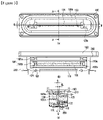
- FIG. 1 is a perspective view of a flat speaker 100 according to an embodiment of the present invention.
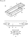
- FIG. 2 is an exploded perspective view of a flat speaker 100 according to an embodiment of the present invention.
- FIG. 3 is a plan view (a), a side view (b), and a cross-sectional view (c)A-A of the flat speaker 100 according to an embodiment of the present invention.
- FIG. 3 illustrates a diaphragm 140 to facilitate identification of the configuration and coupling state of the speaker.
- a flat speaker 100 may include a voice coil plate 150, a diaphragm 140, a damper 110, magnets 130, a yoke 120, a base frame 160, a lead terminal 210 for fixing the flat speaker 100 to an object and a gasket-shaped fixing member 220.
- the voice coil plate 150 may be vertically erected at the center of the flat speaker 100.
- a voice coil 151 may be formed on one or both surfaces of the voice coil plate 150 by being wound or pattern-printed in an oval shape.
- the diaphragm 140 is adhered to an upper end surface of the voice coil plate 150. Therefore, the diaphragm 140 may vibrate according to vertical vibration of the voice coil plate 150 to generate sound.
- the diaphragm 140 may include a connection part (also referred to as an edge) connected to the base frame 160.
- the connection part and the diaphragm 140 may be integrated or separated.
- the damper 110 is bonded to a lower end surface of the voice coil plate 150.
- the damper 110 may serve to assist the vertical vibration of the voice coil plate 150.
- the damper 110 may be made of a cloth having wrinkles.
- the outer periphery of the damper 110 may be adhered and fixed to the base frame 160.
- the damper 110 may have elasticity such that the voice coil plate 150 returns to its original state after vertical vibration.
- the magnets 130 are disposed in parallel on both sides of the voice coil plate 150.
- the magnet 130 may be a rod-shaped magnet having different polarities vertically.
- FIG. 4 is a perspective view (a), a side view (b), and a cross-sectional view (c) of the base frame 160 according to an embodiment of the present invention.
- FIG. 5(a) is a diagram illustrating the configuration and arrangement of a magnetic circuit according to an embodiment of the present invention.
- FIG. 5(b) is a side view of FIG. 5(a).
- FIG. 6 is a perspective view (lower) of a first yoke 120a and a perspective view (upper) of a second yoke 120b according to an embodiment of the present invention.
- the yoke 120 includes a first yoke 120a having a "-" shape in cross section and a second yoke 120b having an "L" shape in cross section.
- the first yoke 120a and the second yoke 120b may be disposed to face each other with respect to the voice coil plate 150 and may be asymmetric.
- the first yoke 120a is disposed on the N-pole or S-pole surface of the magnet 130.
- the second yoke 120b is disposed on the S-pole or N-pole surface of the magnet 130.
- the first yokes 120a and the second yokes 120b are disposed such that different polarities face each other.
- the first yoke is disposed on the N-pole surface of the magnet.
- the second yoke is disposed on the S-pole surface of the magnet.
- the magnetic field starting from the first yoke having a narrow area moves to the second yoke. Accordingly, magnetic field circulation may be efficiently improved.
- the first yoke 120a may include a magnet fixing part 122 protruding in the direction of the magnet 130 to limit movement of the magnet 130.
- the magnet fixing part 122 may be formed through half-blanking processing.
- Half blanking processing is a processing method for forming a shear fault having the same shape as a punch in the processing material by stopping the progress of the punch just before the blanking is completed.
- the magnet fixing part 122 of the first yoke 120a may fix one side of the magnet 130, that is, one side of the magnet 130 disposed adjacent to the voice coil plate 150.
- magnets 130 having different polarities are asymmetrically disposed around the voice coil plate 150. Therefore, an attraction may act between the magnets 130 facing each other.
- the side surface of the magnet 130 is caught in the magnet fixing part 122 and movement of the magnet 130 toward the inside is restricted. Therefore, a bonding process of attaching the magnet 130 to the first yoke 120a may be omitted. Therefore, it is possible to reduce the production process and the use of subsidiary materials.
- the second yoke 120b includes a base portion 123 in contact with the magnet 130 and a bent portion 124 which is bent in an orthogonal direction of the base portion 123.
- the bent portion 124 may be positioned adjacent to a side surface portion of the voice coil plate 150.
- the bent portion 124 may be bent toward a direction opposite to that of the magnet 130.
- the bent portion 124 may be bent upward, and when the second yoke 120b is positioned on a lower surface of the magnet 130, the bent portion 124 may be bent downward.
- an upper surface or a lower surface of the first yoke 120a and a front end surface of the bent portion 124 of the second yoke 120b may be placed on the same horizontal extension line.
- magnets on both sides of the voice coil plate 150 may be disposed at different upper and lower positions as the upper surface or the lower surface of the first yoke 120a and the front end surface of the bent portion 124 of the second yoke 120b are placed on the same horizontal extension line.
- the base frame 160 may include side through holes 162 penetrated through both sides to insert the magnet 130 and the yoke 120 into the inner space, a yoke guide part 161 which fixes both ends of the yoke 120 to limit a minimum distance g between the yokes 120 inserted into the inner space, and at least one insertion holes 163 formed on both sides.
- a jig may be fixed to the base frame 160 through the insertion hole 163, and the center of the voice coil plate 150 may be guided using the fixed jig.
- the yokes 120 disposed on both sides of the voice coil plate 150 may be spaced apart from the voice coil plate 150 by equal distances g1 and g2, and the distance between the yokes 120 may form an air gap g, which is a passage through which air moves when the voice coil plate 150 moves up and down.
- the air gap g may be stably maintained, and the deterioration of the sound quality of the speaker may be prevented even in long-term use.
- the yoke guide part 161 may include a first yoke guide 161a to which both end portions of the first yoke 120a are fixed and a second yoke guide 161b to which both end portions of the second yoke 120b are fixed.
- the yoke guide parts 161 on both sides of the voice coil plate 150 may be asymmetric.
- first yoke guide 161a and the second yoke guide 161b may be disposed to face each other with respect to the voice coil plate 150.
- the yoke guide part 161 may further include a magnet guide part 164 restricting movement of the magnet 130 in the longitudinal direction.
- the magnet 130 may be stably fixed to the base frame 160 by being restricted from moving in a width direction by the magnet fixing part 122 of the first yoke 120a and restricted from moving in a length direction by the magnet guide part 164.
- FIG. 7 is a reference diagram for explaining a difference between a conventional flat speaker (a) and a flat speaker (b) according to an embodiment of the present invention.
- the yokes 120 are disposed on the upper and lower surfaces of the magnet 130 to have the same polarity as the magnet 130 in contact.
- the flat speaker b may expect the same performance as using the magnet 130 having the corresponding pole expanded in size (thickness) by changing and applying the cross section of the yoke 120.
- the flat speaker 100 according to the present invention has the same performance as using a magnet 130 having an S-pole or N-pole with a thickness which has a value of being added by the height of the bent portion 124 of the second yoke 120b, but the size of the magnet 130 actually applied is small, thereby reducing cost.
- yoke 120 having different polarities are disposed opposite to both sides of the voice coil plate of the flat speaker, that is, at a position corresponding to the voice coil.
- the yoke 120' having different polarities and the same cross-section (thickness) is disposed to face a position corresponding to the voice coil 151'.
- the amplitude W' of the voice coil plate 150' is significantly greater than the thickness of the yoke 120', and as a result, a reverse magnetic field is applied to the end of the voice coil plate 151', and vertical vibration of the voice coil plate 150' is not normally progressed.
- the second yoke 120b has a thickness enlarged by the bent portion 124, and thus, even when the amplitude is large, that is, the amplitude of the voice coil plate 150 does not exceed the thickness of the second yoke 120b, thereby a problem of applying a reverse magnetic field to the end of the voice coil 151 is prevented.
- the vertical vibration of the voice coil plate 150 is stably performed, and as a result, low sound as well as high output sound may be smoothly reproduced.
- the magnetic field flows from the N pole to the S pole.
- the magnetic field starting from the N pole has the property of adhering to the nearest S pole at distance. Therefore, the magnetic field (the present invention) starting from the first yoke 120a (N pole) having a smaller area than the second yoke 120b (S pole) is more strongly formed than the magnetic field (prior art) flowing from the N pole having the same area to the S pole. And, this magnetic field can spread wider.
- the spread magnetic field adheres to the nearest S pole, that is, the second yoke 120b disposed on the opposite side with respect to the voice coil plate 150, and the second yoke 120b receives a wide magnetic field transferred from the first yoke 120a using a large area of the bent portion 124 to facilitate circulation of the magnetic field.
- the side through hole 162 of the base frame 160 and the rear (space) of the bent portion 124 of the second yoke 120b may facilitate the air flow inside the speaker, thereby facilitating the vertical movement of the voice coil plate 150 and consequently improving the sound quality of the speaker.
- a flat speaker 100 capable of reducing production processes and reducing costs as well as improving performance such as smooth sound reproduction and sound quality maintenance compared to existing flat speakers.
Landscapes
- Engineering & Computer Science (AREA)
- Physics & Mathematics (AREA)
- Acoustics & Sound (AREA)
- Signal Processing (AREA)
- Multimedia (AREA)
- Audible-Bandwidth Dynamoelectric Transducers Other Than Pickups (AREA)
Applications Claiming Priority (2)
| Application Number | Priority Date | Filing Date | Title |
|---|---|---|---|
| KR1020190114256A KR102205854B1 (ko) | 2019-09-17 | 2019-09-17 | 비대칭 자기체와 베이스 프레임을 포함하는 평판형 스피커 |
| PCT/KR2020/012465 WO2021054708A1 (ko) | 2019-09-17 | 2020-09-16 | 비대칭 자기체와 베이스 프레임을 포함하는 평판형 스피커 |
Publications (2)
| Publication Number | Publication Date |
|---|---|
| EP4033780A1 true EP4033780A1 (de) | 2022-07-27 |
| EP4033780A4 EP4033780A4 (de) | 2023-10-18 |
Family
ID=74237636
Family Applications (1)
| Application Number | Title | Priority Date | Filing Date |
|---|---|---|---|
| EP20864557.2A Withdrawn EP4033780A4 (de) | 2019-09-17 | 2020-09-16 | Flacher lautsprecher mit asymmetrischen magnetischen körpern und grundrahmen |
Country Status (5)
| Country | Link |
|---|---|
| US (1) | US20220337955A1 (de) |
| EP (1) | EP4033780A4 (de) |
| KR (1) | KR102205854B1 (de) |
| CN (1) | CN114731472A (de) |
| WO (1) | WO2021054708A1 (de) |
Families Citing this family (3)
| Publication number | Priority date | Publication date | Assignee | Title |
|---|---|---|---|---|
| EP4437740A1 (de) * | 2021-11-26 | 2024-10-02 | Continental Engineering Services GmbH | Soundaktuator mit robuster positionierung von magnet-polplattenpaketen |
| WO2024168641A1 (zh) * | 2023-02-16 | 2024-08-22 | 瑞声光电科技(常州)有限公司 | 扬声器单体 |
| WO2024168642A1 (zh) * | 2023-02-16 | 2024-08-22 | 瑞声光电科技(常州)有限公司 | 扬声器单体 |
Family Cites Families (13)
| Publication number | Priority date | Publication date | Assignee | Title |
|---|---|---|---|---|
| KR200454507Y1 (ko) * | 2009-06-22 | 2011-07-08 | 주식회사 비에스이 | 마이크로 스피커 |
| JP4814361B2 (ja) * | 2009-07-17 | 2011-11-16 | フォスター電機株式会社 | スピーカユニット |
| KR101138118B1 (ko) * | 2010-03-23 | 2012-04-25 | 서기영 | 평판형 스피커 |
| KR101116659B1 (ko) * | 2010-05-17 | 2012-03-07 | 주식회사 토비스 | 마그네트-요크 홀더를 구비하는 평판형 스피커 |
| KR101119493B1 (ko) | 2010-06-28 | 2012-03-12 | 주식회사 엑셀웨이 | 다수개의 보이스 코일이 연결된 평판형 스피커 |
| KR101119495B1 (ko) * | 2010-07-23 | 2012-03-06 | 주식회사 엑셀웨이 | 평판형 스피커의 자석 플레이트 및 베이스 프레임 구조 |
| KR101200435B1 (ko) * | 2011-05-13 | 2012-11-12 | 주식회사 이엠텍 | 고출력 마이크로 스피커 |
| KR101154250B1 (ko) | 2011-06-08 | 2012-06-13 | 주식회사 엑셀웨이 | 다수개의 자기회로가 수평 연결된 평판형 스피커 |
| KR101201828B1 (ko) * | 2011-06-28 | 2012-11-15 | 주식회사 엑셀웨이 | n개의 자석과 n+1개의 보이스 코일판이 결합되어 형성되는 평판형 스피커 |
| KR20150047748A (ko) * | 2013-10-25 | 2015-05-06 | 주식회사 드림소닉 | 평판형 스피커 |
| KR101717970B1 (ko) * | 2015-04-28 | 2017-03-21 | 민동훈 | 다층 구조의 보이스 코일판 및 이를 포함하는 평판형 스피커 |
| KR101745492B1 (ko) * | 2015-06-24 | 2017-06-12 | 민동훈 | 평판형 스피커 |
| WO2017033459A1 (ja) * | 2015-08-24 | 2017-03-02 | パナソニックIpマネジメント株式会社 | スピーカ用磁気回路、およびこれを用いたスピーカ |
-
2019
- 2019-09-17 KR KR1020190114256A patent/KR102205854B1/ko active Active
-
2020
- 2020-09-16 US US17/760,648 patent/US20220337955A1/en not_active Abandoned
- 2020-09-16 EP EP20864557.2A patent/EP4033780A4/de not_active Withdrawn
- 2020-09-16 CN CN202080064843.1A patent/CN114731472A/zh active Pending
- 2020-09-16 WO PCT/KR2020/012465 patent/WO2021054708A1/ko not_active Ceased
Also Published As
| Publication number | Publication date |
|---|---|
| US20220337955A1 (en) | 2022-10-20 |
| WO2021054708A1 (ko) | 2021-03-25 |
| KR102205854B1 (ko) | 2021-01-21 |
| CN114731472A (zh) | 2022-07-08 |
| EP4033780A4 (de) | 2023-10-18 |
Similar Documents
| Publication | Publication Date | Title |
|---|---|---|
| KR100533715B1 (ko) | 코일판 가이드수단을 구비하는 평판형 스피커 | |
| EP4033780A1 (de) | Flacher lautsprecher mit asymmetrischen magnetischen körpern und grundrahmen | |
| US8649550B2 (en) | Multi-magnet system and speaker using same | |
| EP2472906B1 (de) | Flachlautsprecher und Montageverfahren dafür | |
| CN105491487B (zh) | 扬声器 | |
| KR102061173B1 (ko) | 슬림 자기 코어를 구비한 장방형의 평판형 슬림 스피커 | |
| CN1832635B (zh) | 扬声器装置 | |
| JP5112159B2 (ja) | 電磁型電気音響変換器 | |
| KR100576267B1 (ko) | 다수의 코일판을 구비하는 평판형 스피커 | |
| JP2003032786A (ja) | 角形スピーカ | |
| KR102151222B1 (ko) | 보이스 코일판의 센터 가이드를 구현한 평판형 스피커 | |
| KR101245836B1 (ko) | Tv용 슬림형 스피커 | |
| CN108702577B (zh) | 扬声器 | |
| KR101460431B1 (ko) | 전자기 댐핑 기능을 갖는 전자음향변환기 | |
| KR102079624B1 (ko) | 평판형 스피커 | |
| KR101466786B1 (ko) | 스피커의 서스펜션 | |
| KR100533714B1 (ko) | 폐루프 형상의 코일판을 구비하는 평판스피커 | |
| KR102061174B1 (ko) | 듀얼 방사형의 평판 슬림 스피커 | |
| EP3068144A1 (de) | Lautsprechervorrichtung | |
| KR101363518B1 (ko) | 개선된 자기회로 및 이를 이용한 스피커 | |
| KR102061175B1 (ko) | 다이렉트 엣지를 구비한 진동판 조립체를 포함하는 평판형 슬림 스피커 | |
| KR101256761B1 (ko) | 고출력특성을 갖는 오발타입의 마이크로 스피커유닛트 | |
| JP4598435B2 (ja) | スピーカ | |
| JP2000036997A (ja) | スピーカ装置 | |
| KR101617662B1 (ko) | 요크 폴을 이용한 스피커 자기회로 안정화 장치 |
Legal Events
| Date | Code | Title | Description |
|---|---|---|---|
| STAA | Information on the status of an ep patent application or granted ep patent |
Free format text: STATUS: THE INTERNATIONAL PUBLICATION HAS BEEN MADE |
|
| PUAI | Public reference made under article 153(3) epc to a published international application that has entered the european phase |
Free format text: ORIGINAL CODE: 0009012 |
|
| STAA | Information on the status of an ep patent application or granted ep patent |
Free format text: STATUS: REQUEST FOR EXAMINATION WAS MADE |
|
| 17P | Request for examination filed |
Effective date: 20220414 |
|
| AK | Designated contracting states |
Kind code of ref document: A1 Designated state(s): AL AT BE BG CH CY CZ DE DK EE ES FI FR GB GR HR HU IE IS IT LI LT LU LV MC MK MT NL NO PL PT RO RS SE SI SK SM TR |
|
| DAV | Request for validation of the european patent (deleted) | ||
| DAX | Request for extension of the european patent (deleted) | ||
| A4 | Supplementary search report drawn up and despatched |
Effective date: 20230915 |
|
| RIC1 | Information provided on ipc code assigned before grant |
Ipc: H04R 7/20 20060101ALI20230911BHEP Ipc: H04R 7/16 20060101ALI20230911BHEP Ipc: H04R 1/28 20060101ALI20230911BHEP Ipc: H04R 9/06 20060101ALI20230911BHEP Ipc: H04R 9/04 20060101ALI20230911BHEP Ipc: H04R 9/02 20060101AFI20230911BHEP |
|
| STAA | Information on the status of an ep patent application or granted ep patent |
Free format text: STATUS: THE APPLICATION IS DEEMED TO BE WITHDRAWN |
|
| 18D | Application deemed to be withdrawn |
Effective date: 20240416 |