EP4033779B1 - Akustische vorrichtung - Google Patents
Akustische vorrichtung Download PDFInfo
- Publication number
- EP4033779B1 EP4033779B1 EP22153161.9A EP22153161A EP4033779B1 EP 4033779 B1 EP4033779 B1 EP 4033779B1 EP 22153161 A EP22153161 A EP 22153161A EP 4033779 B1 EP4033779 B1 EP 4033779B1
- Authority
- EP
- European Patent Office
- Prior art keywords
- radiator
- container
- acoustic device
- connecting point
- movement
- Prior art date
- Legal status (The legal status is an assumption and is not a legal conclusion. Google has not performed a legal analysis and makes no representation as to the accuracy of the status listed.)
- Active
Links
Images


Classifications
-
- H—ELECTRICITY
- H04—ELECTRIC COMMUNICATION TECHNIQUE
- H04R—LOUDSPEAKERS, MICROPHONES, GRAMOPHONE PICK-UPS OR LIKE ACOUSTIC ELECTROMECHANICAL TRANSDUCERS; DEAF-AID SETS; PUBLIC ADDRESS SYSTEMS
- H04R1/00—Details of transducers, loudspeakers or microphones
- H04R1/20—Arrangements for obtaining desired frequency or directional characteristics
- H04R1/22—Arrangements for obtaining desired frequency or directional characteristics for obtaining desired frequency characteristic only
- H04R1/28—Transducer mountings or enclosures modified by provision of mechanical or acoustic impedances, e.g. resonator, damping means
- H04R1/2807—Enclosures comprising vibrating or resonating arrangements
- H04R1/283—Enclosures comprising vibrating or resonating arrangements using a passive diaphragm
- H04R1/2834—Enclosures comprising vibrating or resonating arrangements using a passive diaphragm for loudspeaker transducers
-
- H—ELECTRICITY
- H04—ELECTRIC COMMUNICATION TECHNIQUE
- H04R—LOUDSPEAKERS, MICROPHONES, GRAMOPHONE PICK-UPS OR LIKE ACOUSTIC ELECTROMECHANICAL TRANSDUCERS; DEAF-AID SETS; PUBLIC ADDRESS SYSTEMS
- H04R19/00—Electrostatic transducers
- H04R19/02—Loudspeakers
Definitions
- This invention relates to an acoustic device. This invention also relates to a method for extending the low frequency response of a loudspeaker.
- the loudspeaker may form part of a cabinet (or loudspeaker box).
- passive resonators or radiators comprising vibrating radiators, which are associated with loudspeakers or cabinets by suitable suspensions.
- the function of the passive resonators is to extend the response of the loudspeakers, or cabinets, at low frequencies. Examples of such acoustic devices are described in the following patent documents: US9571934B1 , US7158648 , US2001/024508A1 , CN204090070U and US9426548B2 .
- the efficiency of the loudspeaker at certain frequencies may, in some cases, need to be improved; usually, this is done by increasing the weight of the passive resonators.
- the radiators are very heavy. This in turn creates a problem of mechanical vibration transmitted from the passive resonators to the cabinet; another problem concerns the suspensions which, because they are highly compliant, tend to yield under the weight of the passive resonator and, over time, lose their original shape.
- a mechanical vibration transmitted from the radiator to the container (that is, to the cabinet) of the loudspeaker may, in other cases, have to be amplified in order to obtain certain acoustic and/or tactile effects.
- Patent document US2014/064539A1 discloses a speaker wherein one or more masses are provided internally to the cabinet and connected mechanically to the passive resonator, with the attempt to reduce vibrations.
- this solution is disadvantageous because it introduces imbalances that may, on their turn, generate noise or damage to the structure of the speaker.
- the present invention is directed to an acoustic device according to claim 1 and a method according to claim 14. Further aspects of the present invention are defined in the dependent claims.
- This disclosure has for an aim to provide an acoustic device and a method for extending the low frequency response of a loudspeaker to overcome at least one the above mentioned disadvantages of the prior art.
- the acoustic device comprises a container (or frame, or enclosure).
- container is meant a box-shaped body that delimits a space inside it.
- the acoustic device also comprises a passive resonator.
- the passive resonator includes a suspension, connected to the container, and a radiator (or vibrating diaphragm), connected to the suspension.
- radiator is meant a rigid element that can move relative to the container. More specifically, the radiator is surrounded by the suspension.
- the suspension is configured to allow the radiator to oscillate, or vibrate, relative to the container. More specifically, the suspension is compliant, that is to say, elastic.
- the acoustic device also comprises a structure that has a first connecting point, where it is connected to the radiator, and a second connecting point, where it is connected to the container.
- the structure is movable alternately between a first position and a second position, responsive to a vibration of the radiator. More specifically, in a preferred embodiment, the structure is fixed to the radiator at the first connecting point and to the container at the second connecting point and is deformable so it can move between the first position and the second position.
- the structure may be connected movably to the radiator at the first connecting point and to the container at the second connecting point, and it may be rigid.
- the acoustic device also comprises one or more masses, spaced from the radiator and associated with the vibrating structure, so that a movement of the vibrating structure between the first position and the second position causes a corresponding movement of the one or more masses.
- the movement of the one or more masses may act as a counterweight to the movement of the radiator, thus fulfilling a balancing function useful for counteracting a mechanical vibration transmitted from the radiator to the container.
- This solution also has the advantage of making it possible to make an acoustic device which is very compact but which may nevertheless include a passive resonator of large size and mass (hence having a wide range response at low frequencies).
- This solution also has the advantage of making it possible to make an acoustic device which is inertially balanced although not geometrically symmetrical (in effect, it may have a passive resonator on one side only).
- the movement of the one or more masses may further unbalance the system, thus amplifying a mechanical vibration transmitted from the radiator to the container. This is useful for creating certain sound and vibratory effects, for example, in cinema and gaming applications, where the emission of sound is also associated with vibration.
- the structure is made from or includes a deformable elastic material.
- the structure is elastically deformable.
- the structure is elastically deformable from the first to the second position, responsive to a force applied by the radiator and, in the absence of forces applied by the radiator, is positioned at the first position.
- the structure is elastically deformable it is meant here and in the remaining part of the document that the structure as a whole can be moved, through elastic deformation of at least a portion of the structure, from the first to the second position; wherein one or more points or part of the structure may remain undeformed during such a movement.
- the structure includes a compliant mechanism.
- compliant mechanism is meant a flexible mechanism which achieves transmission of force and movement through elastic deformation of the box-shaped body.
- the compliant mechanism may include a material such as polypropylene (PP), polyethylene (PE) or other material which, within defined conditions of mechanical stress, allows withstanding a particularly high (practically infinite) number of deformation cycles.
- the compliant mechanism is formed preferably (at least partly) of a homogeneous material; for example, the compliant mechanism might be made using a combination of different materials; for example, it might include a first part made from a deformable material and a second, rigid part (that is, made from a rigid material); in this context, the first, deformable part is used to make the connecting parts, while the second, rigid part is used to make the vibrating structure.
- the compliant mechanism is elastically deformable and allows the first connecting point and the second connecting point to move in rotation and translation relative to each other.
- a structure of another kind such as, for example, a sliding system (such as brass bushings) or a rolling bearing system, might be provided.
- the rolling elements might be provided with a static preload to prevent slack and friction.
- the structure is movable between the first position and the second position with a roto-translational movement about the first and/or the second connecting point.
- roto-translational movement it is meant that the movement includes both a rotational component and a translational component; in other words, it is a combination of a rotation movement and a translation movement. That way, the structure performs the function of a lever or mechanism between the radiator and the one or more masses.
- the acoustic device comprises a first mass and a second mass.
- the structure has a third connecting point, where it is connected (specifically, fixed) to the container.
- the first and the second mass are symmetrical about the first (or second) connecting point; preferably, the masses are symmetric with respect to the longitudinal axis along which the radiator vibrates. That way, when the radiator moves, the acoustic device is not subject to a rotating moment and is thus more balanced.
- the structure is configured for transforming a translational movement of the radiator along a longitudinal axis in a (purely) translational movement of the mass (or mases) along a longitudinal orientation, in opposite direction with respect to the movement of the radiator.
- the structure is configured for generating, responsive to a translational movement of the radiator, a purely translational movement of one or more mases. If a single mass is provided, that mass moves along the same longitudinal axis along which the radiator moves. If two or more masses are provided, they move along respective axes which are parallel to the longitudinal axis and are arranged according to an axial symmetry with respect to the longitudinal axis.
- the structure may be elongated along a transverse direction.
- the acoustic device is shaped symmetrically with respect to the longitudinal axis (and the passive radiator has a circular shape).
- the first connecting point, the second connecting point and the third connecting point are aligned along the transverse direction; the second connecting point is interposed between the first and the third connecting point.
- the first mass and the second mass are disposed mirror symmetrically to each other about the second connecting point. More specifically, the first connecting point is interposed, along the transverse direction, between the first mass and the second connecting point; the second connecting point is interposed, along the transverse direction, between the second mass and the third connecting point.
- the structure is configured to move from the first position to the second position in response to a movement of the radiator towards the second connecting point, thereby causing a movement of the one or more masses towards the radiator.
- the structure is configured to move from the first position to the second position in response to a longitudinal movement of the radiator in a first direction, thereby causing a movement of the one or more masses along a path that includes a longitudinal component in a second direction, opposite to the first direction.
- the structure and the one or more masses perform the function of balancing, that is to say, of counteracting the mechanical vibration transmitted from the radiator to the container.
- the mass of the loudspeakers can be used as a mass integrated in the radiator of the passive resonator. This improves constructional simplicity.
- the structure is configured to move from the first position to the second position in response to a movement of the radiator towards the second connecting point, thereby causing a movement of the one or more masses towards the radiator.
- the structure is configured to move from the first position to the second position in response to a longitudinal movement of the radiator in a first direction, thereby causing a movement of the one or more masses along a path that includes a longitudinal component in the first direction.
- the structure and the one or more masses perform the function of unbalancing, that is to say, of amplifying the mechanical vibration transmitted from the radiator to the container.
- the container has a first side, where the suspension is connected (hence where the radiator is located) and a second side, opposite the first side.
- the second connecting point is on the second side.
- the second side is without passive resonators.
- the second side may be mounted to a wall or a ceiling.
- the container defines an internal space and the structure is positioned in the internal space.
- the one or more masses are also positioned in the internal space.
- the structure and the one or more masses might be positioned outside the internal space.
- the device also comprises a loudspeaker.
- the loudspeaker includes a diaphragm and an electric actuator to move the diaphragm.
- the vibration of the diaphragm creates a pressure disturbance inside the internal space of the device; this disturbance in turn causes the radiator of the passive resonator to vibrate.
- at least part of the loudspeaker is positioned in the internal space.
- the internal space is delimited by the container, by the passive resonator and (as the case may be) by the loudspeaker.
- the loudspeaker is connected to the passive resonator and is movable together with the radiator. More specifically, inside it, the radiator of the passive resonator, has a hole in which the loudspeaker is positioned (fixed). This solution further improves the compactness of the device.
- This disclosure also provides a method for extending the low frequency response of a loudspeaker.
- the method comprises a step of preparing an acoustic device.
- the acoustic device comprises a container; the container defines an internal space.
- the acoustic device comprises the loudspeaker. At least part of the loudspeaker is positioned in the internal space.
- the motor that moves the loudspeaker is positioned in the internal space.
- the acoustic device comprises a passive resonator, including a suspension that is connected to the container, and a radiator that is connected to the suspension to vibrate relative to the container.
- the electric actuator moves the diaphragm of the loudspeaker, causing the air inside the internal space to vibrate, which in turn moves the radiator of the passive resonator.
- the method comprises a step of transmitting movement from the radiator to one or more masses positioned inside the internal space, to counteract or amplify a mechanical vibration transmitted from the radiator to the container.
- the loudspeaker includes a structure.
- the one or more masses are associated to the structure.
- the structure has at least a first connecting point, where it is connected to the radiator, and a second connecting point, where it is connected to the container.
- the structure moves alternately between a first position and a second position, responsive to a vibration of the radiator.
- the structure is configured for moving the one or more masses in a predetermined direction, which is preferably parallel to the direction along which the radiator moves.
- a predetermined first (translational) movement of the radiator of a first stroke it corresponds (according to the configuration of the structure) a predetermined second (translational) movement of the one or more masses.
- the movement of the radiator and the movement of the masses occur along the same axis or parallel axes.
- the structure is configured so that the movement of the masses responsive to the movement of the radiator occur in opposite direction with respect to the movement of the radiator.
- the stroke of the radiator and the corresponding stroke of the mass may be the same or different, according to the ratio between the mass of the radiator and the mass of the (equivalent mass); for example, if the mass has larger mass than the radiator, the stroke of the radiator is smaller than the corresponding stroke of the mass.
- the structure may for example be configured so that the movement of the masses responsive to the movement of the radiator occur in concurrent direction with respect to the movement of the radiator.
- This disclosure also provides a method for extending the low frequency response of a loudspeaker of a loudspeaker cabinet (or loudspeaker box).
- the method comprises a step of vibrating the diaphragm of the loudspeaker to generate sound waves in an internal space.
- at least part of the loudspeaker is positioned in an internal space of the cabinet.
- the method comprises a step of vibrating (or oscillating) a radiator of a passive resonator included in the cabinet. More specifically, the vibration of the loudspeaker diaphragm causes the radiator of the passive resonator to vibrate.
- the method comprises a step of moving the one or more masses with oscillating motion, in response to the movement of the radiator, so as to counteract or amplify a mechanical vibration transmitted to the container by the oscillation of the radiator.
- this invention provides a "passive resonator" that is self-consistent, that is to say, installable in any loudspeaker cabinet, in the same way as the loudspeaker is installed, thus fulfilling a mechanical vibration balancing function.
- the numeral 1 denotes an acoustic device.
- the numeral 1 denotes a balanced, passive radiator acoustic device.
- the acoustic device 1 comprises a container 2.
- the container 2 constitutes a mounting frame, that is to say, a structure which, thanks to the flanged mounting, transmits the constraining forces to the cabinet in which the device is operatively mounted.
- the acoustic device 1 comprises a passive resonator, comprising a suspension 3 and a radiator (or vibrating diaphragm) 4.
- the radiator 4 is a rigid, oscillating (vibrating) element adapted to displace a quantity of air during (or by the effect of) its movement.
- the acoustic device 1 may also comprise a loudspeaker 71.
- the passive resonator is positioned on a first side 2A of the container 2.
- the container 2 also has a second side 2B, opposite the first side.
- the container 2, the passive resonator and, where provided, the loudspeaker 71 delimit a closed space.
- the loudspeaker 71 When the loudspeaker 71 is active, it causes the air (or other gas) to vibrate inside the closed space; the vibrating air causes the radiator 4 of the passive resonator to oscillate, that is, to resonate, that is to say, it causes it to move with reciprocating motion relative to the container 2; this movement is made possible by the compliance of the suspension 3.
- the radiator 4 moves relatively along a longitudinal direction L.
- the acoustic device 1 comprises a system for balancing the movement of the radiator 4, so as to minimize the displacement of the centre of mass of the acoustic device 1 caused by the vibration of the radiator 4, thereby also minimizing the vibration transmitted from the radiator 4 to the container.
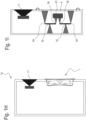
- the system for balancing the movement of the radiator 4 is illustrated schematically in Figures 1A and 1B .
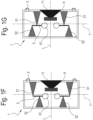
- the acoustic device 1 comprises a system for unbalancing the movement of the radiator 4, so as to maximize the displacement of the centre of mass of the acoustic device 1 caused by the vibration of the radiator 4, thereby also maximizing the vibration transmitted from the radiator 4 to the container.
- the system for unbalancing the movement of the radiator 4 is illustrated schematically in Figure 1C .
- the acoustic device 1 comprises a structure 5 that extends along a transverse direction T, transverse (perpendicular) to the longitudinal direction L.
- the structure 5 is connected to the radiator 4 at a first connecting point 51 and to the container 2 at a second connecting point 52.
- the second connecting point 52 is located on the second side 2B of the container 2.
- the first connecting point 51 is spaced from the second connecting point 52 along the transverse direction T. It should be noted that the first connecting point 51 is located on a first longitudinal side of the structure 5, and the second connecting point 52 is located on a second longitudinal side of the structure 5, opposite the first longitudinal side.
- the structure 5 or a part of it can move with rotational or rototranslational motion relative to the radiator 4 and container 2; more specifically, the structure 5 may be flexible so it can move relative to the radiator 4 and container 2. Thus, the structure 5 works like a lever.
- the device 1 comprises at least a first mass 61 connected to the structure 5.
- the mass 61 is aligned with the first connecting point 51 and the second connecting point 52 along the transverse direction T.
- the second connecting point 52 is interposed, along the transverse direction T, between the first mass 61 and the first connecting point 51.
- moving the radiator 4 along the longitudinal direction L towards the second connecting point 52, that is to say, towards the second side 2B of the container 2 causes the first mass 61 to move away from the second side of the container 2, that is to say, towards the radiator 4.
- the distance L1 along the transverse direction T between the first connecting point 51 and the second connecting point 52 is equal to the distance L2 along the transverse direction T between the second connecting point 52 and the first mass 61, and the first mass 61 has a mass (or weight) that is equal to that of the radiator 4.
- the distance L1 along the transverse direction T between the first connecting point 51 and the second connecting point 52 is less than the distance L2 along the transverse direction T between the second connecting point 52 and the first mass 61, and the first mass 61 has a mass (or weight) that is less than that of the radiator 4.
- the distance L1 along the transverse direction T between the first connecting point 51 and the second connecting point 52 is greater than the distance L2 along the transverse direction T between the second connecting point 52 and the first mass 61, and the first mass 61 has a mass (or weight) that is greater than that of the radiator 4.
- the structure 5 performs the function of lever: the portion of the structure 5 of length L1, between the first connecting point 51 and the second connecting point 52, perform the function of a first lever arm; the portion of the structure 5 of length L2, between the first connecting point 51 and the second connecting point 52, performs the function of a second lever arm, and the second connecting point 52 performs the function of fulcrum.
- a motive force is applied on the first lever arm due to the effect of the movement of the radiator 4, and a resistant force is applied on the second lever arm due to the effect of the mass 61.
- the structure 5 performs the function of double lever: a first lever has the second connecting point 52 as its fulcrum and a second lever has the third connecting point 53 as its fulcrum.
- the first connecting point 51 is interposed between the first mass 61 and the second connecting point 52.
- a distance L3 between the first connecting point 51 and the second connecting point 52 may be greater or smaller than a distance L4 between the first connecting point 51 and the first mass 61, depending on how much the vibration of the container 2 needs to be amplified.
- moving the radiator 4 along the longitudinal direction L towards the second connecting point 52, that is to say, towards the second side 2B of the container 2 causes the first mass 61 to move towards the second connecting point 52, that is to say, towards the second side 2B of the container 2, that is to say away from the radiator 4.
- the device 1 comprises at least a first mass 61 and a second mass 62, both connected to the structure 5.
- the structure 5 has a third connecting point 53 that connects it to the container 2.
- the third connecting point 53 is aligned with the first and the second connecting point 51, 52 along the transverse direction T.
- the first connecting point 51 is interposed, along the transverse direction T, between the second connecting point and the third connecting point 53.
- the third connecting point 53 is located on the same side of the structure 5, that is, its second longitudinal side, as the second connecting point 52.
- the distance L1 between the first connecting point 51 and the second connecting point 52 is equal to the distance between the first connecting point 51 and the third connecting point 53; the distance L2 between the second connecting point 52 and the first mass 61 is equal to the distance between the third connecting point 53 and the second mass 62.
- the distance L1 may be equal to the distance L2 and the first mass 61 and the second mass 62 may each have a mass (or weight) that is half the mass (or weight) of the radiator 4.
- the distance L1 may be less than the distance L2 and the first mass 61 and the second mass 62 may each have a mass (or weight) that is less than half the mass (or weight) of the radiator 4.
- the distance L1 may be greater than the distance L2 and the first mass 61 and the second mass 62 may each have a mass (or weight) that is greater than half the mass (or weight) of the vibrating radiator 4.
- the structure 5 is a flexible, elastic structure.
- the structure 5 is fixed to the second side 2B of the container at the second and the third connecting point 53; the structure 5 is also fixed to the radiator 4 at the first connecting point 51.
- the structure 5 Since the structure 5 is elastic, it will then tend to displace the radiator 4 away from the second side 2B of the container 2 (to its original position) and to displace the first and second masses 61 and 62 away from the radiator 4 (to their original positions). Thus, the structure 5 also performs a function of relieving the suspension 3 in that it contributes to returning the radiator 4 to its original position; the suspension 3 can thus be more flexible.
- the acoustic device 1 does not include a loudspeaker and is configured to be associated with a loudspeaker or a cabinet outside of the device.
- the container 2 might be provided with openings 20 which can put the space inside the container 2 operatively in communication with the space inside a loudspeaker or a cabinet.
- the openings 20 are preferably made on the second side 2B of the container. The acoustic device is thus associable with a loudspeaker or a cabinet.
- the structure 5 includes parts that are in relative motion, connected to each other at articulation points.
- These articulation points constitute joints that allow these parts of the structure to move relative to each other, performing relative movements that include translational movements relative to each other; in addition to relative rotation, the articulation points preferably also allow translational movements.
- the articulation points constitute points (or zones) of constraint, where the parts of the structure are connected in such a way that they can move relative to each other.
- the structure 5 includes first articulation points 54 (or one first articulation point 54) and second articulation points 55 (or one second articulation point 55).
- the first articulation points 54 are connected (directly) to the first connecting points (or zones) 51 and allow the first connecting points 51 to rotate relative to the rest of the structure 5.
- the second articulation points 55 are connected (directly) to the second connecting points (or zones) 52 (or to the third connecting points 53) and allow the second (or the third) connecting points 52 to rotate relative to the rest of the structure 5.
- the second articulation points 55 are located downstream of the first articulation points 54.
- the structure 5 may also comprise third articulation points 56.
- the third articulation points 56 are connected (directly or indirectly) to the masses 61 and allow the masses 61 to perform a (further) rotation relative to the rest of the structure 5.
- the third articulation points 56 are located downstream of the second articulation points 55; the third articulation points 56 are interposed between the second articulation points 55 and the masses 61.
- the structure 5 comprises first articulation points 54, second articulation points 55 and third articulation points 56, spaced from one another and kinematically interposed between the radiator 4 and the one or more masses 61, 62, so that the one or more masses 61, 62 undergo a purely translational movement, responsive to the movement of the radiator 4, the (vibrational) movement of the radiator being a translation movement in its turn.
- the device 1 comprises a single mass 61 connected to the structure 5, preferably at a position lying on an axis of symmetry of the radiator 4.
- the structure 5 may comprise a compliant mechanism.
- the structure 5 has a first connecting point (or zone) 51 that is connected (for example, glued) to the radiator 4.
- This connecting point (or zone) 51 preferably extends in the transverse direction.
- the structure 5 is also connected to the container 2 (specifically, to the second side 2B thereof) at a pair of connecting points 52 and 53.
- the connecting points 52 and 53 are aligned with each other along the transverse direction T.
- the mass 61 is interposed between the connecting points 52 and 53 along the transverse direction T; preferably, the mass 61 is equidistant from the connecting points 52 and 53.
- the mass 61 extends perpendicularly to the longitudinal direction L and to the transverse direction T.
- the third connecting point 53 is located on the same side of the structure 5, that is, its second longitudinal side, as the second connecting point 52; the second longitudinal side is opposite the first side 2A that is connected to the radiator 4.
- the structure 5 has an opening 50 which makes the structure 5 more elastic.
- the mass 61 moves with substantially linear (rectilinear) motion along the longitudinal direction L in axially (mirror) symmetric fashion relative to the radiator 4. This reduces unwanted harmonic components and improves the balancing effect.
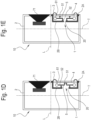
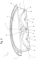
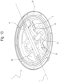
- the acoustic device 1 includes at least one loudspeaker 71. More specifically, the acoustic device 1 may be integrated in a cabinet 10.
- the cabinet 10 comprises a plurality of loudspeakers 71, 72, 73, 74.
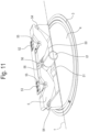
- the loudspeakers 71, 72, 73, 74 are mounted on the radiator 4 of the passive resonator; more specifically, the radiator 4 is surrounded by the suspension 3 connected to the container 2 and includes a plurality of openings in which the loudspeakers 71, 72, 73, 74 are inserted. That way, the loudspeakers 71, 72, 73 74 are movable as one with the radiator 4.
- a cover 21, fixed to the container 2, may be provided above the radiator 4.
- the cover 21 constitutes an elastic suspension element allowing the radiator 4 and the loudspeakers 71, 72, 73, 74 to move relative to the container 2.
- the cabinet 10, that is, the acoustic device 1 may comprise a plurality of structures 501, 502, 503, 504.
- Each structure 501, 502, 503, 504 has a respective first connecting point, where it is connected to the radiator 4, and respective second and third connecting points, where it is connected to the second side 2B of the container 2.
- the structures 501, 502, 503, 504 are disposed in succession along a direction of succession A, perpendicular to the longitudinal direction L and to the transverse direction T.
- the cabinet 10 extends along the direction of succession A.
- the first and the second mass 61, 62 may extend along the direction of succession A to be connected to the structures 501, 502, 503, 504 of the plurality. That way, the structures 501, 502, 503, 504 are connected to each other through the first and the second mass 61 and 62.
Landscapes
- Physics & Mathematics (AREA)
- Engineering & Computer Science (AREA)
- Acoustics & Sound (AREA)
- Signal Processing (AREA)
- Health & Medical Sciences (AREA)
- Otolaryngology (AREA)
- Obtaining Desirable Characteristics In Audible-Bandwidth Transducers (AREA)
- Details Of Audible-Bandwidth Transducers (AREA)
- Surgical Instruments (AREA)
- Seal Device For Vehicle (AREA)
- Sink And Installation For Waste Water (AREA)
Claims (15)
- Akustische Vorrichtung (1), umfassend:- einen Behälter (2);- einen passiven Resonator, der eine mit dem Behälter (2) verbundene Aufhängung (3) und einen mit der Aufhängung (3) verbundenen Strahler (4) einschließt, wobei die Aufhängung (3) ausgelegt ist, um dem Strahler (4) zu ermöglichen, relativ zu dem Behälter (2) zu schwingen;- eine Struktur (5) mit mindestens einem ersten Verbindungspunkt (51), an dem sie mit dem Strahler (4) verbunden ist, und einem zweiten Verbindungspunkt (52, 53), an dem sie mit dem Behälter (2) verbunden ist, wobei die Struktur (5) als Reaktion auf eine Vibration des Strahlers (4) abwechselnd zwischen einer ersten Position und einer zweiten Position bewegbar ist;- eine oder mehrere Massen (61), die von dem Strahler (4) beabstandet und mit der Struktur (5) assoziiert sind, so dass eine Bewegung der Struktur (5) zwischen der ersten Position und der zweiten Position eine entsprechende Bewegung der einen oder der mehreren Massen (61) verursacht,dadurch gekennzeichnet, dass die Struktur (5) dazu ausgelegt ist, als Reaktion auf eine Translationsbewegung des Strahlers (4) entlang einer Längsachse eine rein Translationsbewegung der einen oder der mehreren Massen (61) in einer Richtung parallel zu der Längsachse zu erzeugen.
- Akustische Vorrichtung (1) nach Anspruch 1, wobei die Struktur (5) aus einem verformbaren elastischen Material hergestellt ist oder ein solches einschließt, so dass die Struktur (5) als Reaktion auf eine durch den Strahler (4) aufgebrachte Kraft von der ersten in die zweite Position elastisch verformbar ist und in Abwesenheit von durch den Strahler (4) aufgebrachten Kräften an der ersten Position positioniert ist.
- Akustische Vorrichtung (1) nach Anspruch 2, wobei die Struktur (5) zumindest teilweise aus einem verformbaren elastischen Material hergestellt ist.
- Akustische Vorrichtung (1) nach Anspruch 3, wobei die Struktur (5) einen nachgiebigen Mechanismus einschließt.
- Akustische Vorrichtung (1) nach einem der vorhergehenden Ansprüche, wobei als Reaktion auf eine Bewegung der Struktur (5) zwischen der ersten Position und der zweiten Position mindestens ein Abschnitt der Struktur mit einer Rotations-Translationsbewegung um den ersten und/oder den zweiten Verbindungspunkt (51, 52, 53) bewegbar ist.
- Akustische Vorrichtung (1) nach einem der vorhergehenden Ansprüche, umfassend eine erste Masse (61) und eine zweite Masse (61), wobei die Struktur (5) einen dritten Verbindungspunkt (52, 53) aufweist, an dem sie mit dem Behälter (2) verbunden ist.
- Akustische Vorrichtung (1) nach Anspruch 6, wobei die erste und die zweite Masse (61) symmetrisch um die Achse angeordnet sind, entlang der sich der Strahler bewegt.
- Akustische Vorrichtung (1) nach einem der vorhergehenden Ansprüche, wobei eine der folgenden Bedingungen stattfindet:(i) die Struktur (5) dazu ausgelegt ist, sich als Reaktion auf eine Bewegung des Strahlers (4) in Richtung des zweiten Verbindungspunkts (52, 53) von der ersten Position in die zweite Position zu bewegen, wodurch eine Bewegung der einen oder der mehreren Massen (61) in Richtung des Strahlers (4) verursacht wird;(ii) die Struktur (5) dazu ausgelegt ist, sich als Reaktion auf eine Bewegung des Strahlers (4) in Richtung des zweiten Verbindungspunkts (52, 53) von der ersten Position in die zweite Position zu bewegen, wodurch eine Bewegung der einen oder der mehreren Massen (61) vom Strahler (4) wegführend verursacht wird.
- Akustische Vorrichtung (1) nach einem der vorhergehenden Ansprüche, wobei die Struktur (5) erste Gelenkpunkte (54), zweite Gelenkpunkte (55) und dritte Gelenkpunkte (56) umfasst, die voneinander beabstandet sind und kinematisch zwischen dem Strahler (4) und der einen oder den mehreren Massen (61) angeordnet sind, so dass die eine oder die mehreren Massen (61) als Reaktion auf eine Bewegung des Strahlers (4) eine rein Translationsbewegung durchlaufen.
- Akustische Vorrichtung (1) nach einem der vorhergehenden Ansprüche, wobei der Behälter (2) eine erste Seite (2A), an der die Aufhängung (3) verbunden ist, und eine zweite Seite (2B) gegenüber der ersten Seite (2A) aufweist, wobei der zweite Verbindungspunkt (52, 53) auf der zweiten Seite (2B) liegt und wobei die zweite Seite (2B) ohne passive Resonatoren ist.
- Akustische Vorrichtung (1) nach einem der vorhergehenden Ansprüche, wobei der Behälter (2) einen Innenraum definiert und die Struktur (5) in dem Innenraum positioniert ist.
- Akustische Vorrichtung (1) nach einem der vorhergehenden Ansprüche, wobei der Behälter (2) einen Innenraum definiert und die Vorrichtung ferner einen Lautsprecher (71, 72, 73, 74) umfasst, wobei mindestens ein Teil des Lautsprechers (71, 72, 73, 74) innerhalb des Innenraums positioniert ist.
- Akustische Vorrichtung (1) nach Anspruch 12, wobei der Lautsprecher (71, 72, 73, 74) mit dem Strahler (4) des passiven Resonators verbunden ist und zusammen mit dem Strahler (4) bewegbar ist.
- Verfahren zum Erweitern des Niederfrequenzbereichs eines Lautsprechers (71), wobei das Verfahren das Vorbereiten einer akustischen Vorrichtung (1) nach einem der vorhergehenden Ansprüche umfasst, wobei die akustische Vorrichtungeinen Behälter (2), der einen Innenraum definiert,den Lautsprecher (71), wobei mindestens ein Teil des Lautsprechers (71) innerhalb des Innenraums positioniert ist, undeinen passiven Resonator umfasst, der eine Aufhängung (3), die mit dem Behälter (2) verbunden ist, und einen Strahler (4), der mit der Aufhängung (3) verbunden ist, einschließt, um relativ zu dem Behälter (2) zu schaukeln, dadurch gekennzeichnet, dass es einen Schritt zum Übertragen einer Bewegung von dem Strahler (4) auf eine oder mehrere Massen (61), die innerhalb des Innenraums positioniert sind, umfasst.
- Verfahren nach Anspruch 14, wobei eine Struktur (5) bereitgestellt ist, wobei die eine oder die mehreren Massen mit der Struktur assoziiert sind, wobei die Struktur (5) mindestens einen ersten Verbindungspunkt (51), an dem sie mit dem Strahler (4) verbunden ist, und einen zweiten Verbindungspunkt (52, 53), an dem sie mit dem Behälter (2) verbunden ist, aufweist,
wobei sich die Struktur (5) als Reaktion auf eine Vibration des Strahlers (4) abwechselnd zwischen einer ersten Position und einer zweiten Position bewegt, um einer mechanischen Vibration entgegenzuwirken oder zu verstärken, die durch den Vibrationsstrahler (4) auf den Behälter (2) übertragen wird.
Applications Claiming Priority (1)
| Application Number | Priority Date | Filing Date | Title |
|---|---|---|---|
| IT102021000001487A IT202100001487A1 (it) | 2021-01-26 | 2021-01-26 | Dispositivo acustico |
Publications (3)
| Publication Number | Publication Date |
|---|---|
| EP4033779A1 EP4033779A1 (de) | 2022-07-27 |
| EP4033779C0 EP4033779C0 (de) | 2024-12-04 |
| EP4033779B1 true EP4033779B1 (de) | 2024-12-04 |
Family
ID=75660126
Family Applications (1)
| Application Number | Title | Priority Date | Filing Date |
|---|---|---|---|
| EP22153161.9A Active EP4033779B1 (de) | 2021-01-26 | 2022-01-25 | Akustische vorrichtung |
Country Status (4)
| Country | Link |
|---|---|
| US (1) | US11785374B2 (de) |
| EP (1) | EP4033779B1 (de) |
| CN (1) | CN114793312A (de) |
| IT (1) | IT202100001487A1 (de) |
Families Citing this family (1)
| Publication number | Priority date | Publication date | Assignee | Title |
|---|---|---|---|---|
| EP4207809B1 (de) | 2021-12-29 | 2025-02-26 | Powersoft SpA | Schalldiffusor und verfahren zur herstellung eines schalldiffusors |
Family Cites Families (10)
| Publication number | Priority date | Publication date | Assignee | Title |
|---|---|---|---|---|
| US6704426B2 (en) * | 1999-03-02 | 2004-03-09 | American Technology Corporation | Loudspeaker system |
| US7158648B2 (en) | 2002-07-30 | 2007-01-02 | Harman International Industries, Incorporated | Loudspeaker system with extended bass response |
| KR20040110982A (ko) * | 2003-06-10 | 2004-12-31 | 마쯔시다덴기산교 가부시키가이샤 | 스피커 장치 |
| JP2005039454A (ja) * | 2003-07-18 | 2005-02-10 | Pioneer Electronic Corp | ドア用スピーカ装置及びドアパネル |
| US20070092096A1 (en) * | 2003-07-21 | 2007-04-26 | Roman Litovsky | Passive acoustical radiating |
| AU2013296585B2 (en) | 2012-07-30 | 2017-02-23 | Treefrog Developments, Inc. | Weatherproof loudspeaker and speaker assembly |
| US9055370B2 (en) * | 2012-08-31 | 2015-06-09 | Bose Corporation | Vibration-reducing passive radiators |
| US9571934B2 (en) | 2014-03-26 | 2017-02-14 | Bose Corporation | Acoustic device with passive radiators |
| CN204090070U (zh) * | 2014-07-02 | 2015-01-07 | 音品电子(深圳)有限公司 | 主动扬声器与被动辐射器一体化的喇叭结构及音箱 |
| TWI734382B (zh) * | 2020-02-17 | 2021-07-21 | 大陸商東莞寶德電子有限公司 | 環狀輻射音箱結構 |
-
2021
- 2021-01-26 IT IT102021000001487A patent/IT202100001487A1/it unknown
-
2022
- 2022-01-24 US US17/582,281 patent/US11785374B2/en active Active
- 2022-01-25 EP EP22153161.9A patent/EP4033779B1/de active Active
- 2022-01-26 CN CN202210097100.5A patent/CN114793312A/zh active Pending
Also Published As
| Publication number | Publication date |
|---|---|
| IT202100001487A1 (it) | 2022-07-26 |
| EP4033779A1 (de) | 2022-07-27 |
| EP4033779C0 (de) | 2024-12-04 |
| US11785374B2 (en) | 2023-10-10 |
| CN114793312A (zh) | 2022-07-26 |
| US20220240003A1 (en) | 2022-07-28 |
Similar Documents
| Publication | Publication Date | Title |
|---|---|---|
| EP2503792B1 (de) | Lautsprecher mit beweglichem Anker mit Vibrationsunterdrückung | |
| US4445065A (en) | Non-prismal beam resonator | |
| US7626316B2 (en) | Passive self-tuning resonator system | |
| US9055370B2 (en) | Vibration-reducing passive radiators | |
| US9473855B2 (en) | Moving armature receiver assemblies with vibration suppression | |
| US10381909B2 (en) | Linear vibration motor | |
| FI104302B (fi) | Menetelmä ja laitteisto kaiuttimen mekaanisten resonanssien vaimentamiseksi | |
| EP4033779B1 (de) | Akustische vorrichtung | |
| JP6643696B2 (ja) | リニアフィーダ | |
| KR100887455B1 (ko) | 진동 저감 브래킷 | |
| US20210126558A1 (en) | Vibrational Energy Harvesters With Reduced Wear | |
| KR100400914B1 (ko) | 진동 노이즈 감소장치 | |
| US3417630A (en) | Vibratory apparatus | |
| JP2022553142A (ja) | 防音サスペンションシステム | |
| JP7178674B2 (ja) | 制振装置 | |
| JP6703268B2 (ja) | リニアフィーダ | |
| EP1048876A2 (de) | Regulierbarer Dämpfer | |
| JP5012532B2 (ja) | 吸音体、吸音体群及び音響室 | |
| JP2023035771A (ja) | 防振構造体 | |
| JP2002336787A (ja) | 振動装置 | |
| JP2024106608A (ja) | 振動板およびそれを用いた電子機器 | |
| JPH11257421A (ja) | 制振装置 | |
| KR100901088B1 (ko) | 발전 디바이스 및 이를 구비하는 진동형 발전 어셈블리 | |
| JP2017034756A (ja) | 発電装置 | |
| JP2015115656A (ja) | 音響装置 |
Legal Events
| Date | Code | Title | Description |
|---|---|---|---|
| PUAI | Public reference made under article 153(3) epc to a published international application that has entered the european phase |
Free format text: ORIGINAL CODE: 0009012 |
|
| STAA | Information on the status of an ep patent application or granted ep patent |
Free format text: STATUS: THE APPLICATION HAS BEEN PUBLISHED |
|
| AK | Designated contracting states |
Kind code of ref document: A1 Designated state(s): AL AT BE BG CH CY CZ DE DK EE ES FI FR GB GR HR HU IE IS IT LI LT LU LV MC MK MT NL NO PL PT RO RS SE SI SK SM TR |
|
| STAA | Information on the status of an ep patent application or granted ep patent |
Free format text: STATUS: REQUEST FOR EXAMINATION WAS MADE |
|
| 17P | Request for examination filed |
Effective date: 20230125 |
|
| RBV | Designated contracting states (corrected) |
Designated state(s): AL AT BE BG CH CY CZ DE DK EE ES FI FR GB GR HR HU IE IS IT LI LT LU LV MC MK MT NL NO PL PT RO RS SE SI SK SM TR |
|
| GRAP | Despatch of communication of intention to grant a patent |
Free format text: ORIGINAL CODE: EPIDOSNIGR1 |
|
| STAA | Information on the status of an ep patent application or granted ep patent |
Free format text: STATUS: GRANT OF PATENT IS INTENDED |
|
| INTG | Intention to grant announced |
Effective date: 20240716 |
|
| GRAS | Grant fee paid |
Free format text: ORIGINAL CODE: EPIDOSNIGR3 |
|
| GRAA | (expected) grant |
Free format text: ORIGINAL CODE: 0009210 |
|
| STAA | Information on the status of an ep patent application or granted ep patent |
Free format text: STATUS: THE PATENT HAS BEEN GRANTED |
|
| AK | Designated contracting states |
Kind code of ref document: B1 Designated state(s): AL AT BE BG CH CY CZ DE DK EE ES FI FR GB GR HR HU IE IS IT LI LT LU LV MC MK MT NL NO PL PT RO RS SE SI SK SM TR |
|
| REG | Reference to a national code |
Ref country code: CH Ref legal event code: EP |
|
| REG | Reference to a national code |
Ref country code: DE Ref legal event code: R096 Ref document number: 602022008266 Country of ref document: DE |
|
| REG | Reference to a national code |
Ref country code: IE Ref legal event code: FG4D |
|
| U01 | Request for unitary effect filed |
Effective date: 20241212 |
|
| U07 | Unitary effect registered |
Designated state(s): AT BE BG DE DK EE FI FR IT LT LU LV MT NL PT RO SE SI Effective date: 20241223 |
|
| U20 | Renewal fee for the european patent with unitary effect paid |
Year of fee payment: 4 Effective date: 20250130 |
|
| PG25 | Lapsed in a contracting state [announced via postgrant information from national office to epo] |
Ref country code: HR Free format text: LAPSE BECAUSE OF FAILURE TO SUBMIT A TRANSLATION OF THE DESCRIPTION OR TO PAY THE FEE WITHIN THE PRESCRIBED TIME-LIMIT Effective date: 20241204 |
|
| PG25 | Lapsed in a contracting state [announced via postgrant information from national office to epo] |
Ref country code: ES Free format text: LAPSE BECAUSE OF FAILURE TO SUBMIT A TRANSLATION OF THE DESCRIPTION OR TO PAY THE FEE WITHIN THE PRESCRIBED TIME-LIMIT Effective date: 20241204 |
|
| PG25 | Lapsed in a contracting state [announced via postgrant information from national office to epo] |
Ref country code: NO Free format text: LAPSE BECAUSE OF FAILURE TO SUBMIT A TRANSLATION OF THE DESCRIPTION OR TO PAY THE FEE WITHIN THE PRESCRIBED TIME-LIMIT Effective date: 20250304 |
|
| PG25 | Lapsed in a contracting state [announced via postgrant information from national office to epo] |
Ref country code: GR Free format text: LAPSE BECAUSE OF FAILURE TO SUBMIT A TRANSLATION OF THE DESCRIPTION OR TO PAY THE FEE WITHIN THE PRESCRIBED TIME-LIMIT Effective date: 20250305 |
|
| PG25 | Lapsed in a contracting state [announced via postgrant information from national office to epo] |
Ref country code: RS Free format text: LAPSE BECAUSE OF FAILURE TO SUBMIT A TRANSLATION OF THE DESCRIPTION OR TO PAY THE FEE WITHIN THE PRESCRIBED TIME-LIMIT Effective date: 20250304 |
|
| PG25 | Lapsed in a contracting state [announced via postgrant information from national office to epo] |
Ref country code: SM Free format text: LAPSE BECAUSE OF FAILURE TO SUBMIT A TRANSLATION OF THE DESCRIPTION OR TO PAY THE FEE WITHIN THE PRESCRIBED TIME-LIMIT Effective date: 20241204 |
|
| PG25 | Lapsed in a contracting state [announced via postgrant information from national office to epo] |
Ref country code: PL Free format text: LAPSE BECAUSE OF FAILURE TO SUBMIT A TRANSLATION OF THE DESCRIPTION OR TO PAY THE FEE WITHIN THE PRESCRIBED TIME-LIMIT Effective date: 20241204 |
|
| PG25 | Lapsed in a contracting state [announced via postgrant information from national office to epo] |
Ref country code: IS Free format text: LAPSE BECAUSE OF FAILURE TO SUBMIT A TRANSLATION OF THE DESCRIPTION OR TO PAY THE FEE WITHIN THE PRESCRIBED TIME-LIMIT Effective date: 20250404 |
|
| PG25 | Lapsed in a contracting state [announced via postgrant information from national office to epo] |
Ref country code: SK Free format text: LAPSE BECAUSE OF FAILURE TO SUBMIT A TRANSLATION OF THE DESCRIPTION OR TO PAY THE FEE WITHIN THE PRESCRIBED TIME-LIMIT Effective date: 20241204 |
|
| PG25 | Lapsed in a contracting state [announced via postgrant information from national office to epo] |
Ref country code: CZ Free format text: LAPSE BECAUSE OF FAILURE TO SUBMIT A TRANSLATION OF THE DESCRIPTION OR TO PAY THE FEE WITHIN THE PRESCRIBED TIME-LIMIT Effective date: 20241204 |
|
| REG | Reference to a national code |
Ref country code: CH Ref legal event code: PL |
|
| PG25 | Lapsed in a contracting state [announced via postgrant information from national office to epo] |
Ref country code: MC Free format text: LAPSE BECAUSE OF FAILURE TO SUBMIT A TRANSLATION OF THE DESCRIPTION OR TO PAY THE FEE WITHIN THE PRESCRIBED TIME-LIMIT Effective date: 20241204 |
|
| PLBE | No opposition filed within time limit |
Free format text: ORIGINAL CODE: 0009261 |
|
| STAA | Information on the status of an ep patent application or granted ep patent |
Free format text: STATUS: NO OPPOSITION FILED WITHIN TIME LIMIT |
|
| PG25 | Lapsed in a contracting state [announced via postgrant information from national office to epo] |
Ref country code: CH Free format text: LAPSE BECAUSE OF NON-PAYMENT OF DUE FEES Effective date: 20250131 |
|
| 26N | No opposition filed |
Effective date: 20250905 |