EP4033641B1 - Stator für einen/eine permanenterregten elektromotor/drehfeldmaschine - Google Patents
Stator für einen/eine permanenterregten elektromotor/drehfeldmaschine Download PDFInfo
- Publication number
- EP4033641B1 EP4033641B1 EP21215233.4A EP21215233A EP4033641B1 EP 4033641 B1 EP4033641 B1 EP 4033641B1 EP 21215233 A EP21215233 A EP 21215233A EP 4033641 B1 EP4033641 B1 EP 4033641B1
- Authority
- EP
- European Patent Office
- Prior art keywords
- stator
- winding
- electric motor
- yoke
- rotating field
- Prior art date
- Legal status (The legal status is an assumption and is not a legal conclusion. Google has not performed a legal analysis and makes no representation as to the accuracy of the status listed.)
- Active
Links
Images



Classifications
-
- H—ELECTRICITY
- H02—GENERATION; CONVERSION OR DISTRIBUTION OF ELECTRIC POWER
- H02K—DYNAMO-ELECTRIC MACHINES
- H02K1/00—Details of the magnetic circuit
- H02K1/06—Details of the magnetic circuit characterised by the shape, form or construction
- H02K1/12—Stationary parts of the magnetic circuit
-
- H—ELECTRICITY
- H02—GENERATION; CONVERSION OR DISTRIBUTION OF ELECTRIC POWER
- H02K—DYNAMO-ELECTRIC MACHINES
- H02K1/00—Details of the magnetic circuit
- H02K1/06—Details of the magnetic circuit characterised by the shape, form or construction
- H02K1/12—Stationary parts of the magnetic circuit
- H02K1/14—Stator cores with salient poles
- H02K1/146—Stator cores with salient poles consisting of a generally annular yoke with salient poles
-
- H—ELECTRICITY
- H02—GENERATION; CONVERSION OR DISTRIBUTION OF ELECTRIC POWER
- H02K—DYNAMO-ELECTRIC MACHINES
- H02K1/00—Details of the magnetic circuit
- H02K1/06—Details of the magnetic circuit characterised by the shape, form or construction
- H02K1/12—Stationary parts of the magnetic circuit
- H02K1/16—Stator cores with slots for windings
-
- H—ELECTRICITY
- H02—GENERATION; CONVERSION OR DISTRIBUTION OF ELECTRIC POWER
- H02K—DYNAMO-ELECTRIC MACHINES
- H02K1/00—Details of the magnetic circuit
- H02K1/06—Details of the magnetic circuit characterised by the shape, form or construction
- H02K1/12—Stationary parts of the magnetic circuit
- H02K1/18—Means for mounting or fastening magnetic stationary parts on to, or to, the stator structures
- H02K1/185—Means for mounting or fastening magnetic stationary parts on to, or to, the stator structures to outer stators
-
- H—ELECTRICITY
- H02—GENERATION; CONVERSION OR DISTRIBUTION OF ELECTRIC POWER
- H02K—DYNAMO-ELECTRIC MACHINES
- H02K11/00—Structural association of dynamo-electric machines with electric components or with devices for shielding, monitoring or protection
- H02K11/01—Structural association of dynamo-electric machines with electric components or with devices for shielding, monitoring or protection for shielding from electromagnetic fields, i.e. structural association with shields
- H02K11/014—Shields associated with stationary parts, e.g. stator cores
-
- H—ELECTRICITY
- H02—GENERATION; CONVERSION OR DISTRIBUTION OF ELECTRIC POWER
- H02K—DYNAMO-ELECTRIC MACHINES
- H02K11/00—Structural association of dynamo-electric machines with electric components or with devices for shielding, monitoring or protection
- H02K11/01—Structural association of dynamo-electric machines with electric components or with devices for shielding, monitoring or protection for shielding from electromagnetic fields, i.e. structural association with shields
- H02K11/014—Shields associated with stationary parts, e.g. stator cores
- H02K11/0141—Shields associated with casings, enclosures or brackets
-
- H—ELECTRICITY
- H02—GENERATION; CONVERSION OR DISTRIBUTION OF ELECTRIC POWER
- H02K—DYNAMO-ELECTRIC MACHINES
- H02K11/00—Structural association of dynamo-electric machines with electric components or with devices for shielding, monitoring or protection
- H02K11/30—Structural association with control circuits or drive circuits
- H02K11/33—Drive circuits, e.g. power electronics
-
- H—ELECTRICITY
- H02—GENERATION; CONVERSION OR DISTRIBUTION OF ELECTRIC POWER
- H02K—DYNAMO-ELECTRIC MACHINES
- H02K21/00—Synchronous motors having permanent magnets; Synchronous generators having permanent magnets
- H02K21/12—Synchronous motors having permanent magnets; Synchronous generators having permanent magnets with stationary armatures and rotating magnets
- H02K21/14—Synchronous motors having permanent magnets; Synchronous generators having permanent magnets with stationary armatures and rotating magnets with magnets rotating within the armatures
- H02K21/16—Synchronous motors having permanent magnets; Synchronous generators having permanent magnets with stationary armatures and rotating magnets with magnets rotating within the armatures having annular armature cores with salient poles
-
- H—ELECTRICITY
- H02—GENERATION; CONVERSION OR DISTRIBUTION OF ELECTRIC POWER
- H02K—DYNAMO-ELECTRIC MACHINES
- H02K3/00—Details of windings
- H02K3/04—Windings characterised by the conductor shape, form or construction, e.g. with bar conductors
- H02K3/28—Layout of windings or of connections between windings
-
- H—ELECTRICITY
- H02—GENERATION; CONVERSION OR DISTRIBUTION OF ELECTRIC POWER
- H02K—DYNAMO-ELECTRIC MACHINES
- H02K3/00—Details of windings
- H02K3/42—Means for preventing or reducing eddy-current losses in the winding heads, e.g. by shielding
-
- H—ELECTRICITY
- H02—GENERATION; CONVERSION OR DISTRIBUTION OF ELECTRIC POWER
- H02K—DYNAMO-ELECTRIC MACHINES
- H02K3/00—Details of windings
- H02K3/04—Windings characterised by the conductor shape, form or construction, e.g. with bar conductors
-
- H—ELECTRICITY
- H02—GENERATION; CONVERSION OR DISTRIBUTION OF ELECTRIC POWER
- H02K—DYNAMO-ELECTRIC MACHINES
- H02K3/00—Details of windings
- H02K3/46—Fastening of windings on the stator or rotor structure
Definitions
- the invention relates to a stator for a permanent magnet electric motor/induction machine with a laminated core made of stator laminations and a yoke winding.
- Overlapping winding systems are usually used for high-speed electric motors such as permanent magnet synchronous machines or asynchronous machines.
- the small number of coil turns required at high speeds leads to low inductances.
- unwanted harmonics arise in the phase current, resulting in increased rotor losses.
- These losses can become so large that countermeasures are necessary.
- Appropriate countermeasures are typically passive low-pass filters based on coils and capacitors. The disadvantage of these solutions is that they usually require a relatively large amount of installation space.
- stators for electric motors are known in which non-magnetic connecting elements are used between the stator sheet and the soft magnetic shield.
- a stator for a permanent magnet electric motor/rotating field machine with a laminated core made of stator laminations and a yoke winding is proposed.
- the yoke winding comprises an inner winding part, which is arranged radially inside the stator lamination in at least one winding receptacle, and an outer winding part, which is arranged radially outside the stator lamination on an outer surface of the laminated core.
- a soft magnetic shield is formed around the entire circumference of the outer winding part.
- At least one non-magnetic connecting element is also arranged between the stator lamination and the soft magnetic shield, which in particular contacts the stator lamination and the soft magnetic shield ring.
- connection between the stator core and the shield ring of the yoke-wound stator is made using a non-magnetically conductive connecting part. This pairing increases the leakage inductance and also prevents the unwanted magnetic short circuit between these two components.
- the laminated core is formed in one piece. In this way, the inductance and component strength of the laminated core of the stator are optimized.
- Stators of this type in the technical field at hand are usually designed in such a way that the inner winding part and the outer winding part are connected to one another via a stator yoke. This is a prerequisite for a yoke winding, whereby a stator yoke is also referred to as a yoke.
- the at least one non-magnetic connecting element is made of plastic and a non-magnetic connecting element is arranged between adjacent winding poles of the yoke winding. It is advantageous that a connecting element made of plastic meets the requirements with regard to non-magnetic conductivity and is easy to manufacture and can be optimally adapted to the geometry of the stator sheet.
- the respective non-magnetic connecting element is arranged at a distance from the respective adjacent winding poles of the yoke winding. In this way, the desired effect of a non-magnetic connecting element is achieved by means of a material-saving solution.
- the connecting element is a cast, which is formed over the outer winding part.
- the advantage of this is that the cast is formed completely between the stator sheet and the shield ring, which, in addition to the non-magnetic connection, also protects the stator sheet from moisture, dust, contamination, temperature influences, vibration and contact and provides electrical insulation.
- the at least one winding receptacle is designed as a groove. In this way, a tooth coil winding of the yoke winding can be implemented.
- the yoke winding is designed to be 6-pole or 6-slot. In a further advantageous embodiment of the stator, the yoke winding is designed to be 12-pole or 12-slot.
- the above embodiments of the yoke winding have optimal properties with regard to the use of the stator in a rotating field machine/permanently excited electric motor.
- a rotating field machine/permanently excited electric motor with a stator according to the above disclosure is also proposed, in which a rotor with permanent magnets is arranged within the stator sheet. In this way, the rotating field machine/permanently excited electric motor is implemented in a functional manner.
- the rotating field machine/permanently excited electric motor it is connected directly to a 2-level inverter. Due to the increased inductance provided by the stator of the rotating field machine/permanently excited electric motor according to the invention, the harmonics in the current are reduced, so that the motor can be operated directly on a 2-level inverter without additional measures. Accordingly, the use of an upstream filter or operation on a complex multi-level converter is obsolete.
- Figure 1 is a schematic sectional view of a rotating field machine/permanently excited electric motor with a rotor 8 and a 6-pole or 6-slot stator comprising a soft magnetic shield 5 and a non-magnetic connecting element 6.
- the stator of the permanent-excited electric motor/rotating field machine comprises a laminated core 1 made of stator laminations 11 and a 6-pole or 6-slot yoke winding 2.
- the laminated core 1 is formed in one piece.
- the rotor 8 comprises permanent magnets and is arranged within the stator sheet 11.
- the rotating field machine/permanently excited electric motor is directly connected to a 2-stage inverter (not shown).
- the 6-pole or 6-slot yoke winding 2 comprises an inner winding part 21, which is arranged radially inside the stator sheet 11 in a respective winding receptacle 3, and an outer winding part 22, which is arranged radially outside the stator sheet 11 on an outer surface 4 of the laminated core 1.
- the inner winding part 21 and the outer winding part 22 are connected to one another via a stator yoke and the respective winding receptacle 3 is designed as a groove.
- a soft magnetic shield 5 is formed around the entire circumference of the outer winding part 22.
- non-magnetic connecting elements 6 are arranged, which contact the stator sheet 11 and the soft magnetic shield ring 5.
- the non-magnetic connecting elements 6 are made of plastic and one non-magnetic connecting element 6 is arranged between adjacent winding poles 7 of the winding 2.
- the respective non-magnetic connecting element 6 is arranged at a distance from the respective adjacent winding poles 7 of the winding 2.
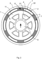
- Figure 2 shows a further schematic sectional view of a rotating field machine/permanently excited electric motor with a rotor 8 and a 6-pole or 6-slot stator comprising a soft magnetic shield 5 and a non-magnetic connecting element 6.
- the yoke winding 2 of the stator is 6-pole or 6-slot and the non-magnetic connecting element 6 is a cast which is formed over the respective outer winding part 22.
- the respective winding receptacle 3 is formed as a slot.
- Figure 3 is a schematic sectional view of a rotating field machine/permanently excited electric motor with a rotor 8 and a 12-pole or 12-slot stator comprising a soft magnetic shield 5 and a non-magnetic connecting element 6.
- the respective winding receptacle 3 is designed as a slot and the yoke winding 2 of the stator is designed as 12-pole or 12-slot.
- Figure 4 shows a further schematic sectional view of a rotating field machine/permanently excited electric motor with a rotor 8 and a 6-pole or 6-slot stator comprising a soft magnetic shield 5 and a non-magnetic connecting element 6.
- the yoke winding 2 of the stator is 6-pole or 6-slot and the non-magnetic connecting element 6 is a cast which is formed over the respective outer winding part 22.
- the respective winding receptacle 3 is formed without a slot.
- FIG 5 is a further schematic sectional view of a rotating field machine/permanently excited electric motor with a rotor 8 and a 12-pole or 12-slot stator comprising a soft magnetic shield 5 and a non-magnetic connecting element 6.
- the yoke winding 2 of the stator is 12-pole or 6-slot and the non-magnetic connecting element 6 is a cast which is formed over the respective outer winding part 22.
- the respective winding receptacle 3 is formed without a slot.
Landscapes
- Engineering & Computer Science (AREA)
- Power Engineering (AREA)
- Physics & Mathematics (AREA)
- Electromagnetism (AREA)
- Microelectronics & Electronic Packaging (AREA)
- Iron Core Of Rotating Electric Machines (AREA)
- Synchronous Machinery (AREA)
Description
- Die Erfindung betrifft einen Stator für einen/eine permanenterregten Elektromotor/Drehfeldmaschine mit einem Blechpaket aus Statorblechen und einer Jochwicklung.
- Üblicherweise werden für hochdrehende elektrische Motoren wie permanentmagneterregte Synchronmaschinen oder Asynchronmaschinen überlappende Wicklungssysteme eingesetzt. Die bei hohen Drehzahlen notwendigen kleinen Spulenwindungszahlen führen allerdings zu geringen Induktivitäten. Infolgedessen entstehen unerwünschte Oberschwingungen im Strangstrom, woraus erhöhte Rotorverluste resultieren. Diese Verluste können dabei derart groß werden, dass Gegenmaßnahmen notwendig sind. Entsprechende Gegenmaßnahmen sind typischerweise passive Tiefpassfilter, welche auf Spulen und Kondensatoren basieren. Nachteilig an diesen Lösungen ist, dass in der Regel ein vergleichsweise großer Bauraumbedarf benötigt wird.
- Ein anderer Ansatz für Gegenmaßnahmen ist die Verwendung eines Mehr-Level-Umrichters, dessen Komplexität jedoch gegenüber dem üblicherweise verwendeten Umrichter stark erhöht ist und woraus ebenfalls ein größerer Platzbedarf resultiert.
- Aus den Dokumenten
JP S59 70154 A DE 44 04 585 C2 sind beispielsweise Statoren für Elektromotoren bekannt, bei welchen nichtmagnetische Verbindungselemente zwischen Statorblech und weichmagnetischen Schirm verwendet werden. - Es ist daher Aufgabe der vorliegenden Erfindung, einen Stator für einen/eine permanenterregten Elektromotor/Drehfeldmaschine mit einem Blechpaket aus Statorblechen und einer Jochwicklung bereitzustellen, bei welchem/welcher ein Betrieb an einem Pulswechselrichter bei einer hohen Drehzahl mit reduzierten Rotorverlusten ohne stromglättende Zusatzmaßnahmen möglich ist.
- Diese Aufgabe wird durch die Merkmalskombination gemäß Patentanspruch 1 gelöst.
- Erfindungsgemäß wird ein Stator für einen/eine permanenterregten Elektromotor/Drehfeldmaschine mit einem Blechpaket aus Statorblechen und einer Jochwicklung vorgeschlagen. Die Jochwicklung umfasst einen inneren Wicklungsteil, welcher radial innerhalb des Statorblechs in wenigstens einer Wicklungsaufnahme angeordnet ist, und einen äußeren Wicklungsteil, welcher radial außerhalb des Statorblechs an einer Außenoberfläche des Blechpakets angeordnet ist. Darüber hinaus ist um den äußeren Wicklungsteil vollumfänglich ein weichmagnetischer Schirm ausgebildet. Zwischen dem Statorblech und dem weichmagnetischen Schirm ist ferner wenigstens ein nichtmagnetisches Verbindungselement angeordnet, welches das Statorblech und den weichmagnetischen Schirmring insbesondere kontaktiert.
- Vorteilhaft daran ist, dass die Verbindung zwischen dem Statorblechpaket und dem Schirmring des jochbewickelten Stators dabei über ein nicht magnetisch leitfähiges Verbindungsteil gelöst wird. Diese Paarung erhöht die Streuinduktivität und verhindert dabei außerdem den unerwünschten magnetischen Kurzschluss zwischen diesen beiden Bauteilen.
- In einer bevorzugten Ausführungsform der Erfindung ist das Blechpaket einstückig ausgebildet. Auf diese Weise sind Induktivität und Bauteilfestigkeit des Blechpakets des Stators optimiert.
- Gattungsbildende Statoren im vorliegenden technischen Gebiet sind üblicherweise derart ausgebildet, dass der innere Wicklungsteil und der äußere Wicklungsteil über einen Statorrückschluss miteinander verbunden sind. Dies ist eine Voraussetzung für eine Jochwicklung, wobei ein Statorrückschluss auch als Joch bezeichnet wird.
- Erfindungsgemäß ist vorgesehen, dass das wenigstens eine nichtmagnetische Verbindungselement aus Kunststoff ist und jeweils ein nichtmagnetisches Verbindungselement zwischen benachbarten Wicklungspolen der Jochwicklung angeordnet ist. Dabei ist günstig, dass ein Verbindungselement aus Kunststoff die Anforderungen hinsichtlich einer nichtmagnetischen Leitfähigkeit erfüllt sowie einfach Herzustellen und dabei optimal an die Geometrie des Statorblechs anpassbar ist.
- Ferner ist vorgesehen, dass das jeweilige nichtmagnetische Verbindungselement beabstandet von den jeweiligen benachbarten Wicklungspolen der Jochwicklung angeordnet ist. Dadurch wird mittels einer materialsparenden Lösung die gewünschte Wirkung eines nichtmagnetischen Verbindungselements erreicht.
- In einer alternativen nicht erfindungsgemäßen Ausführungsform des vorliegenden Stators ist vorgesehen, dass das wenigstens eine nichtmagnetische Verbindungselement ein Verguss ist, welcher über den äußeren Wicklungsteil ausgebildet ist. Vorteilhaft daran ist, dass der Verguss vollumfänglich zwischen dem Statorblech und dem Schirmring ausgebildet ist, wodurch neben der nichtmagnetischen Verbindung ferner das Statorblech vor Feuchtigkeit, Staub, Verunreinigung, Temperatureinflüssen, Erschütterung und Berührung geschützt und eine elektrische Isolation bereitgestellt ist.
- In einer weiteren vorteilhaften Ausführung ist vorgesehen, dass die wenigstens eine Wicklungsaufnahme als eine Nut ausgebildet ist. Auf diese Weise ist eine Zahnspulenwicklung der Jochwicklung umsetzbar.
- In einem Ausführungsbeispiel der Erfindung ist vorgesehen, dass die Jochwicklung 6-polig bzw. 6-nutig ausgebildet ist. In einer weiteren vorteilhaften Ausführungsform des Stators ist die Jochwicklung 12-polig bzw. 12-nutig ausgebildet. Die vorstehenden Ausführungsvarianten der Jochwicklung weisen optimale Eigenschaften hinsichtlich der Anwendung des Stators in einer/einem Drehfeldmaschine/permanenterregten Elektromotor auf.
- Erfindungsgemäß wird ferner eine/ein Drehfeldmaschine/permanenterregter Elektromotor mit einem Stator entsprechend der vorstehenden Offenbarung vorgeschlagen, bei welchem innerhalb des Statorblechs ein Rotor mit Permanentmagneten angeordnet ist. Auf diese Weise ist die/der Drehfeldmaschine/permanenterregte Elektromotor funktionsfähig umgesetzt.
- In einer bevorzugten Ausführungsform der/des Drehfeldmaschine/permanenterregten Elektromotors, ist diese/dieser direkt an einem 2-Stufen-Wechselrichter angeschlossen. Aufgrund der vergrößerten Induktivität durch den erfindungsgemäßen Stator der/des Drehfeldmaschine/permanenterregten Elektromotors sind die Oberschwingungen im Strom reduziert, sodass der Motor ohne Zusatzmaßnahmen direkt an einem 2-Level-Wechselrichter betreibbar ist. Dementsprechend ist die Anwendung eines vorgeschalteten Filters oder der Betrieb an einem aufwändigen Multi-Level-Umrichter obsolet.
- Die vorstehend offenbarten Merkmale sind beliebig kombinierbar, soweit dies technisch möglich ist und diese nicht im Widerspruch zueinander stehen.
- Andere vorteilhafte Weiterbildungen der Erfindung sind in den Unteransprüchen gekennzeichnet bzw. werden nachstehend zusammen mit der Beschreibung der bevorzugten Ausführung der Erfindung anhand der Figuren näher dargestellt. Es zeigen:
- Fig. 1
- eine schematische Schnittansicht einer/eines Drehfeldmaschine/permanenterregten Elektromotors mit einem Rotor und einem 6-poligen bzw. 6-nutigen Stator umfassend einen weichmagnetischen Schirm und ein nichtmagnetisches Verbindungselement,
- Fig. 2
- eine weitere schematische Schnittansicht einer/eines Drehfeldmaschine/permanenterregten Elektromotors mit einem Rotor und einem 6-poligen bzw. 6-nutigen Stator umfassend einen weichmagnetischen Schirm und ein nichtmagnetisches Verbindungselement,
- Fig. 3
- eine schematische Schnittansicht einer/eines Drehfeldmaschine/permanenterregten Elektromotors mit einem Rotor und einem 12-poligen bzw. 12-nutigen Stator umfassend einen weichmagnetischen Schirm und ein nichtmagnetisches Verbindungselement,
- Fig. 4
- eine weitere schematische Schnittansicht einer/eines Drehfeldmaschine/permanenterregten Elektromotors mit einem Rotor und einem 6-poligen bzw. 6-nutigen Stator umfassend einen weichmagnetischen Schirm und ein nichtmagnetisches Verbindungselement und
- Fig. 5
- eine weitere schematische Schnittansicht einer/eines Drehfeldmaschine/permanenterregten Elektromotors mit einem Rotor und einem 12-poligen bzw. 12-nutigen Stator umfassend einen weichmagnetischen Schirm und ein nichtmagnetisches Verbindungselement.
- Die Figuren sind beispielhaft schematisch. Gleiche Bezugszeichen in den Figuren weisen auf gleiche funktionale und/oder strukturelle Merkmale hin.
- In
Figur 1 ist eine schematische Schnittansicht einer/eines Drehfeldmaschine/permanenterregten Elektromotors mit einem Rotor 8 und einem 6-poligen bzw. 6-nutigen Stator umfassend einen weichmagnetischen Schirm 5 und ein nichtmagnetisches Verbindungselement 6 offenbart. Der Stator des/der permanenterregten Elektromotors/Drehfeldmaschine umfasst ein Blechpaket 1 aus Statorblechen 11 sowie eine 6-polig bzw. 6-nutig ausgebildete Jochwicklung 2. Außerdem ist das Blechpaket 1 einstückig ausgebildet. - Des Weiteren umfasst der Rotor 8 Permanentmagneten und ist innerhalb des Statorblechs 11 angeordnet. Außerdem ist die/der Drehfeldmaschine/permanenterregte Elektromotor direkt an einem 2-Stufen-Wechselrichter (nicht gezeigt) angeschlossen.
- Ferner umfasst die 6-polig bzw. 6-nutig ausgebildete Jochwicklung 2 jeweils einen inneren Wicklungsteil 21, welcher radial innerhalb des Statorblechs 11 in jeweils einer Wicklungsaufnahme 3 angeordnet ist, und jeweils einen äußeren Wicklungsteil 22, welcher radial außerhalb des Statorblechs 11 an einer Außenoberfläche 4 des Blechpakets 1 angeordnet ist.
- Der innere Wicklungsteil 21 und der äußere Wicklungsteil 22 sind über einen Statorrückschluss miteinander verbunden und die jeweilige Wicklungsaufnahme 3 ist als eine Nut ausgebildet. Darüber hinaus ist um den äußeren Wicklungsteil 22 vollumfänglich ein weichmagnetischer Schirm 5 ausgebildet.
- Zwischen dem Statorblech 11 und dem weichmagnetischen Schirm 5 sind sechs nichtmagnetische Verbindungselemente 6 angeordnet, welche das Statorblech 11 und den weichmagnetischen Schirmring 5 kontaktieren. Dabei sind die nichtmagnetischen Verbindungselemente 6 aus Kunststoff und jeweils ein nichtmagnetisches Verbindungselement 6 ist zwischen benachbarten Wicklungspolen 7 der Wicklung 2 angeordnet. Außerdem ist das jeweilige nichtmagnetische Verbindungselement 6 beabstandet von den jeweiligen benachbarten Wicklungspolen 7 der Wicklung 2 angeordnet.
- Nachdem die nachfolgenden Ausführungen im Wesentlichen die gleichen funktionalen und/oder strukturellen Merkmale aufweisen, wird im Folgenden lediglich auf unterschiedliche Merkmale eingegangen.
-
Figur 2 zeigt eine weitere schematische Schnittansicht einer/eines Drehfeldmaschine/permanenterregten Elektromotors mit einem Rotor 8 und einem 6-poligen bzw. 6-nutigen Stator umfassend einen weichmagnetischen Schirm 5 und ein nichtmagnetisches Verbindungselement 6. Die Jochwicklung 2 des Stators ist 6-polig bzw. 6-nutig und das nichtmagnetische Verbindungselement 6 ist ein Verguss, welcher über den jeweiligen äußeren Wicklungsteil 22 ausgebildet ist. Ferner ist die jeweilige Wicklungsaufnahme 3 als eine Nut ausgebildet. - In
Figur 3 ist eine schematische Schnittansicht einer/eines Drehfeldmaschine/permanenterregten Elektromotors mit einem Rotor 8 und einem 12-poligen bzw. 12-nutigen Stator umfassend einen weichmagnetischen Schirm 5 und ein nichtmagnetisches Verbindungselement 6 dargestellt. Dabei ist die jeweilige Wicklungsaufnahme 3 als eine Nut und die Jochwicklung 2 des Stators 12-polig bzw. 12-nutig ausgebildet. -
Figur 4 zeigt eine weitere schematische Schnittansicht einer/eines Drehfeldmaschine/permanenterregten Elektromotors mit einem Rotor 8 und einem 6-poligen bzw. 6-nutigen Stator umfassend einen weichmagnetischen Schirm 5 und ein nichtmagnetisches Verbindungselement 6. In der dargestellten Ausführungsvariante ist die Jochwicklung 2 des Stators 6-polig bzw. 6-nutig ausgebildet und das nichtmagnetische Verbindungselement 6 ist ein Verguss, welcher über den jeweiligen äußeren Wicklungsteil 22 ausgebildet ist. Darüber hinaus ist die jeweilige Wicklungsaufnahme 3 ohne eine Nut ausgebildet. - In
Figur 5 ist eine weitere schematische Schnittansicht einer/eines Drehfeldmaschine/permanenterregten Elektromotors mit einem Rotor 8 und einem 12-poligen bzw. 12-nutigen Stator umfassend einen weichmagnetischen Schirm 5 und ein nichtmagnetisches Verbindungselement 6 gezeigt. Die Jochwicklung 2 des Stators ist 12-polig bzw. 6-nutig ausgebildet und das nichtmagnetische Verbindungselement 6 ist ein Verguss, welcher über den jeweiligen äußeren Wicklungsteil 22 ausgebildet ist. Darüber hinaus ist die jeweilige Wicklungsaufnahme 3 ohne eine Nut ausgebildet. - Die Erfindung beschränkt sich in ihrer Ausführung nicht auf die vorstehend angegebenen bevorzugten Ausführungsbeispiele. Änderungen und/oder Modifikationen der beschriebenen Ausführungsformen werden als alternative Formen der Erfindung angesehen, sofern sie nicht vom Umfang der Erfindung abweichen, der durch die beigefügten Ansprüche definiert ist.
Claims (7)
- Stator für einen/eine permanenterregten Elektromotor/Drehfeldmaschine mit einem Blechpaket (1) aus Statorblechen (11) und einer Jochwicklung (2),wobei die Jochwicklung (2) einen inneren Wicklungsteil (21), welcher radial innerhalb des Statorblechs (11) in wenigstens einer Wicklungsaufnahme (3) angeordnet ist, und einen äußeren Wicklungsteil (22), welcher radial außerhalb des Statorblechs (11) an einer Außenoberfläche (4) des Blechpakets (1) angeordnet ist, umfasst,wobei um den äußeren Wicklungsteil (22) vollumfänglich ein weichmagnetischer Schirm (5) ausgebildet ist,wobei zwischen dem Statorblech (11) und dem weichmagnetischen Schirm (5) wenigstens ein nichtmagnetisches Verbindungselement (6) angeordnet ist, welches das Statorblech (11) und den weichmagnetischen Schirmring (5) kontaktiert,dadurch gekennzeichnet, dass das wenigstens eine nichtmagnetische Verbindungselement (6) aus Kunststoff ist und jeweils ein nichtmagnetisches Verbindungselement (6) zwischen benachbarten Wicklungspolen (7) der Jochwicklung (2) angeordnet ist,wobei das jeweilige nichtmagnetische Verbindungselement (6) beabstandet von den jeweiligen benachbarten Wicklungspolen (7) der Jochwicklung (2) angeordnet ist.
- Stator gemäß Anspruch 1, wobei das Blechpaket (1) einstückig ausgebildet ist.
- Stator gemäß einem der vorhergehenden Ansprüche,
wobei die wenigstens eine Wicklungsaufnahme (3) als eine Nut ausgebildet ist. - Stator gemäß einem der vorhergehenden Ansprüche,
wobei die Jochwicklung (2) 6-polig bzw. 6-nutig ausgebildet ist. - Stator gemäß einem der vorhergehenden Ansprüche,
wobei die Jochwicklung (2) 12-polig bzw. 12-nutig ausgebildet ist. - Drehfeldmaschine/Permanenterregter Elektromotor mit einem Stator (1) gemäß einem der vorhergehenden Ansprüche,
wobei innerhalb des Statorblechs (11) ein Rotor (8) mit Permanentmagneten angeordnet ist. - Drehfeldmaschine/Permanenterregter Elektromotor nach Anspruch 6,
wobei diese direkt an einem 2-Stufen-Wechselrichter angeschlossen ist.
Applications Claiming Priority (1)
| Application Number | Priority Date | Filing Date | Title |
|---|---|---|---|
| DE102021101162.0A DE102021101162A1 (de) | 2021-01-20 | 2021-01-20 | Stator für einen/eine permanenterregten Elektromotor/Drehfeldmaschine |
Publications (3)
| Publication Number | Publication Date |
|---|---|
| EP4033641A1 EP4033641A1 (de) | 2022-07-27 |
| EP4033641C0 EP4033641C0 (de) | 2025-01-29 |
| EP4033641B1 true EP4033641B1 (de) | 2025-01-29 |
Family
ID=78918739
Family Applications (1)
| Application Number | Title | Priority Date | Filing Date |
|---|---|---|---|
| EP21215233.4A Active EP4033641B1 (de) | 2021-01-20 | 2021-12-16 | Stator für einen/eine permanenterregten elektromotor/drehfeldmaschine |
Country Status (4)
| Country | Link |
|---|---|
| US (1) | US12081078B2 (de) |
| EP (1) | EP4033641B1 (de) |
| CN (1) | CN114825676B (de) |
| DE (1) | DE102021101162A1 (de) |
Family Cites Families (11)
| Publication number | Priority date | Publication date | Assignee | Title |
|---|---|---|---|---|
| DE1146184B (de) | 1960-05-20 | 1963-03-28 | Bbc Brown Boveri & Cie | Wechselstrommaschine mit ueber den Ruecken der Statorwickelkoepfe angeordneten magnetischen Schirmen |
| JPS5970154A (ja) * | 1982-10-14 | 1984-04-20 | Matsushita Electric Ind Co Ltd | 小形電動機 |
| DE4404585C2 (de) * | 1994-02-12 | 1998-04-09 | Sen Rainer Born | Stator mit Ringkernspulen für elektrische Maschinen |
| JP4269544B2 (ja) * | 2000-09-14 | 2009-05-27 | 株式会社デンソー | 複数ロータ型同期機 |
| KR100860606B1 (ko) | 2006-12-28 | 2008-09-26 | 한국전기연구원 | 내전형 영구자석 여자 횡자속 전동기 |
| CN102340190A (zh) * | 2011-09-16 | 2012-02-01 | 天津市松正电动汽车技术股份有限公司 | 一种电机定子铁芯叠片结构 |
| CN105186749B (zh) * | 2015-10-22 | 2017-12-05 | 山东大学 | 一种环形轭部双绕组混合励磁永磁电动机 |
| CN206595874U (zh) * | 2017-03-31 | 2017-10-27 | 广东威灵电机制造有限公司 | 无刷电机的定子及具有其的电机 |
| CN108900014A (zh) * | 2018-08-03 | 2018-11-27 | 珠海凯邦电机制造有限公司 | 一种定子铁芯、定子和电机 |
| FR3100399B1 (fr) * | 2019-08-27 | 2021-09-24 | Moving Magnet Tech | Machine à bobinage toroïdal |
| CN111555483B (zh) | 2020-06-04 | 2021-09-03 | 南通大学 | 一种双层定子模块式调磁电机 |
-
2021
- 2021-01-20 DE DE102021101162.0A patent/DE102021101162A1/de active Pending
- 2021-12-16 EP EP21215233.4A patent/EP4033641B1/de active Active
-
2022
- 2022-01-14 CN CN202210041473.0A patent/CN114825676B/zh active Active
- 2022-01-19 US US17/578,582 patent/US12081078B2/en active Active
Also Published As
| Publication number | Publication date |
|---|---|
| EP4033641C0 (de) | 2025-01-29 |
| CN114825676B (zh) | 2025-10-21 |
| EP4033641A1 (de) | 2022-07-27 |
| CN114825676A (zh) | 2022-07-29 |
| US20220231579A1 (en) | 2022-07-21 |
| DE102021101162A1 (de) | 2022-07-21 |
| US12081078B2 (en) | 2024-09-03 |
Similar Documents
| Publication | Publication Date | Title |
|---|---|---|
| EP2483991B1 (de) | Bürstenloser synchronmotor | |
| DE102012012605B4 (de) | Synchronmotor | |
| DE102006025396B4 (de) | A-phasiger bürstenloser Motor | |
| DE102014222064B4 (de) | Elektrische Maschine | |
| DE102011088370A1 (de) | Elektrischer Motor mit eingebetteten Permanentmagneten | |
| DE102013103665A1 (de) | Elektrische Maschine | |
| EP2550721B1 (de) | Elektrische maschine und lenkungsvorrichtung | |
| DE102011054243A1 (de) | Drehende elektrische Maschine | |
| EP2770616A1 (de) | Elektrische Maschine mit geteiltem Stator | |
| DE102011116586A1 (de) | Motor | |
| EP3146619B1 (de) | Elektrische maschine | |
| DE102017127157A1 (de) | Rotor für einen Axialflussmotor | |
| DE102010043970A1 (de) | Elektrische Maschine für einen Lenkantrieb | |
| DE102012217363B4 (de) | Elektrische Maschine mit Doppelluftspalt | |
| DE102020115642B3 (de) | Elektrischer Motor und Leiterplatte | |
| WO2010145841A2 (de) | Stator für einen elektromotor | |
| DE102014114929A1 (de) | Zahnwicklung mit Kammern | |
| DE102018211462B4 (de) | Elektrische rotierende maschine | |
| EP4033641B1 (de) | Stator für einen/eine permanenterregten elektromotor/drehfeldmaschine | |
| EP3309933A1 (de) | Statorpaket für elektrische maschine | |
| WO2013127435A1 (de) | Elektrische maschine | |
| EP2901541B1 (de) | Elektromotor | |
| DE112022001200T5 (de) | Ankerwicklung und Verfahren zum Herstellen derselben | |
| DE102009029472A1 (de) | Permanentmagneterregte elektrische Maschine mit reduziertem Lastmoment | |
| DE102021100721A1 (de) | Stator und elektrische Maschine |
Legal Events
| Date | Code | Title | Description |
|---|---|---|---|
| PUAI | Public reference made under article 153(3) epc to a published international application that has entered the european phase |
Free format text: ORIGINAL CODE: 0009012 |
|
| STAA | Information on the status of an ep patent application or granted ep patent |
Free format text: STATUS: THE APPLICATION HAS BEEN PUBLISHED |
|
| AK | Designated contracting states |
Kind code of ref document: A1 Designated state(s): AL AT BE BG CH CY CZ DE DK EE ES FI FR GB GR HR HU IE IS IT LI LT LU LV MC MK MT NL NO PL PT RO RS SE SI SK SM TR |
|
| STAA | Information on the status of an ep patent application or granted ep patent |
Free format text: STATUS: REQUEST FOR EXAMINATION WAS MADE |
|
| 17P | Request for examination filed |
Effective date: 20230118 |
|
| RBV | Designated contracting states (corrected) |
Designated state(s): AL AT BE BG CH CY CZ DE DK EE ES FI FR GB GR HR HU IE IS IT LI LT LU LV MC MK MT NL NO PL PT RO RS SE SI SK SM TR |
|
| GRAP | Despatch of communication of intention to grant a patent |
Free format text: ORIGINAL CODE: EPIDOSNIGR1 |
|
| STAA | Information on the status of an ep patent application or granted ep patent |
Free format text: STATUS: GRANT OF PATENT IS INTENDED |
|
| RIC1 | Information provided on ipc code assigned before grant |
Ipc: H02K 3/46 20060101ALN20240801BHEP Ipc: H02K 3/04 20060101ALN20240801BHEP Ipc: H02K 11/01 20160101ALI20240801BHEP Ipc: H02K 1/18 20060101AFI20240801BHEP |
|
| INTG | Intention to grant announced |
Effective date: 20240830 |
|
| GRAS | Grant fee paid |
Free format text: ORIGINAL CODE: EPIDOSNIGR3 |
|
| GRAA | (expected) grant |
Free format text: ORIGINAL CODE: 0009210 |
|
| STAA | Information on the status of an ep patent application or granted ep patent |
Free format text: STATUS: THE PATENT HAS BEEN GRANTED |
|
| AK | Designated contracting states |
Kind code of ref document: B1 Designated state(s): AL AT BE BG CH CY CZ DE DK EE ES FI FR GB GR HR HU IE IS IT LI LT LU LV MC MK MT NL NO PL PT RO RS SE SI SK SM TR |
|
| REG | Reference to a national code |
Ref country code: GB Ref legal event code: FG4D Free format text: NOT ENGLISH |
|
| REG | Reference to a national code |
Ref country code: CH Ref legal event code: EP |
|
| REG | Reference to a national code |
Ref country code: DE Ref legal event code: R096 Ref document number: 502021006500 Country of ref document: DE |
|
| REG | Reference to a national code |
Ref country code: IE Ref legal event code: FG4D Free format text: LANGUAGE OF EP DOCUMENT: GERMAN |
|
| U01 | Request for unitary effect filed |
Effective date: 20250129 |
|
| U07 | Unitary effect registered |
Designated state(s): AT BE BG DE DK EE FI FR IT LT LU LV MT NL PT RO SE SI Effective date: 20250205 |
|
| PG25 | Lapsed in a contracting state [announced via postgrant information from national office to epo] |
Ref country code: RS Free format text: LAPSE BECAUSE OF FAILURE TO SUBMIT A TRANSLATION OF THE DESCRIPTION OR TO PAY THE FEE WITHIN THE PRESCRIBED TIME-LIMIT Effective date: 20250429 |
|
| PG25 | Lapsed in a contracting state [announced via postgrant information from national office to epo] |
Ref country code: PL Free format text: LAPSE BECAUSE OF FAILURE TO SUBMIT A TRANSLATION OF THE DESCRIPTION OR TO PAY THE FEE WITHIN THE PRESCRIBED TIME-LIMIT Effective date: 20250129 |
|
| PG25 | Lapsed in a contracting state [announced via postgrant information from national office to epo] |
Ref country code: ES Free format text: LAPSE BECAUSE OF FAILURE TO SUBMIT A TRANSLATION OF THE DESCRIPTION OR TO PAY THE FEE WITHIN THE PRESCRIBED TIME-LIMIT Effective date: 20250129 |
|
| PG25 | Lapsed in a contracting state [announced via postgrant information from national office to epo] |
Ref country code: IS Free format text: LAPSE BECAUSE OF FAILURE TO SUBMIT A TRANSLATION OF THE DESCRIPTION OR TO PAY THE FEE WITHIN THE PRESCRIBED TIME-LIMIT Effective date: 20250529 Ref country code: NO Free format text: LAPSE BECAUSE OF FAILURE TO SUBMIT A TRANSLATION OF THE DESCRIPTION OR TO PAY THE FEE WITHIN THE PRESCRIBED TIME-LIMIT Effective date: 20250429 |
|
| PG25 | Lapsed in a contracting state [announced via postgrant information from national office to epo] |
Ref country code: HR Free format text: LAPSE BECAUSE OF FAILURE TO SUBMIT A TRANSLATION OF THE DESCRIPTION OR TO PAY THE FEE WITHIN THE PRESCRIBED TIME-LIMIT Effective date: 20250129 |
|
| PG25 | Lapsed in a contracting state [announced via postgrant information from national office to epo] |
Ref country code: GR Free format text: LAPSE BECAUSE OF FAILURE TO SUBMIT A TRANSLATION OF THE DESCRIPTION OR TO PAY THE FEE WITHIN THE PRESCRIBED TIME-LIMIT Effective date: 20250430 |
|
| PG25 | Lapsed in a contracting state [announced via postgrant information from national office to epo] |
Ref country code: SM Free format text: LAPSE BECAUSE OF FAILURE TO SUBMIT A TRANSLATION OF THE DESCRIPTION OR TO PAY THE FEE WITHIN THE PRESCRIBED TIME-LIMIT Effective date: 20250129 |
|
| PG25 | Lapsed in a contracting state [announced via postgrant information from national office to epo] |
Ref country code: CZ Free format text: LAPSE BECAUSE OF FAILURE TO SUBMIT A TRANSLATION OF THE DESCRIPTION OR TO PAY THE FEE WITHIN THE PRESCRIBED TIME-LIMIT Effective date: 20250129 |
|
| PG25 | Lapsed in a contracting state [announced via postgrant information from national office to epo] |
Ref country code: SK Free format text: LAPSE BECAUSE OF FAILURE TO SUBMIT A TRANSLATION OF THE DESCRIPTION OR TO PAY THE FEE WITHIN THE PRESCRIBED TIME-LIMIT Effective date: 20250129 |
|
| PLBE | No opposition filed within time limit |
Free format text: ORIGINAL CODE: 0009261 |
|
| STAA | Information on the status of an ep patent application or granted ep patent |
Free format text: STATUS: NO OPPOSITION FILED WITHIN TIME LIMIT |
|
| 26N | No opposition filed |
Effective date: 20251030 |
|
| U20 | Renewal fee for the european patent with unitary effect paid |
Year of fee payment: 5 Effective date: 20251222 |