EP4033554A1 - Berührungsbildschirm und mobiles endgerät - Google Patents
Berührungsbildschirm und mobiles endgerät Download PDFInfo
- Publication number
- EP4033554A1 EP4033554A1 EP19945526.2A EP19945526A EP4033554A1 EP 4033554 A1 EP4033554 A1 EP 4033554A1 EP 19945526 A EP19945526 A EP 19945526A EP 4033554 A1 EP4033554 A1 EP 4033554A1
- Authority
- EP
- European Patent Office
- Prior art keywords
- area
- display area
- touch
- circuit
- signal input
- Prior art date
- Legal status (The legal status is an assumption and is not a legal conclusion. Google has not performed a legal analysis and makes no representation as to the accuracy of the status listed.)
- Pending
Links
Images


Classifications
-
- G—PHYSICS
- G06—COMPUTING OR CALCULATING; COUNTING
- G06F—ELECTRIC DIGITAL DATA PROCESSING
- G06F3/00—Input arrangements for transferring data to be processed into a form capable of being handled by the computer; Output arrangements for transferring data from processing unit to output unit, e.g. interface arrangements
- G06F3/01—Input arrangements or combined input and output arrangements for interaction between user and computer
- G06F3/03—Arrangements for converting the position or the displacement of a member into a coded form
- G06F3/041—Digitisers, e.g. for touch screens or touch pads, characterised by the transducing means
- G06F3/0412—Digitisers structurally integrated in a display
-
- G—PHYSICS
- G06—COMPUTING OR CALCULATING; COUNTING
- G06F—ELECTRIC DIGITAL DATA PROCESSING
- G06F3/00—Input arrangements for transferring data to be processed into a form capable of being handled by the computer; Output arrangements for transferring data from processing unit to output unit, e.g. interface arrangements
- G06F3/01—Input arrangements or combined input and output arrangements for interaction between user and computer
- G06F3/03—Arrangements for converting the position or the displacement of a member into a coded form
- G06F3/041—Digitisers, e.g. for touch screens or touch pads, characterised by the transducing means
- G06F3/0416—Control or interface arrangements specially adapted for digitisers
- G06F3/04164—Connections between sensors and controllers, e.g. routing lines between electrodes and connection pads
-
- G—PHYSICS
- G06—COMPUTING OR CALCULATING; COUNTING
- G06F—ELECTRIC DIGITAL DATA PROCESSING
- G06F3/00—Input arrangements for transferring data to be processed into a form capable of being handled by the computer; Output arrangements for transferring data from processing unit to output unit, e.g. interface arrangements
- G06F3/01—Input arrangements or combined input and output arrangements for interaction between user and computer
- G06F3/03—Arrangements for converting the position or the displacement of a member into a coded form
- G06F3/041—Digitisers, e.g. for touch screens or touch pads, characterised by the transducing means
- G06F3/0416—Control or interface arrangements specially adapted for digitisers
-
- G—PHYSICS
- G06—COMPUTING OR CALCULATING; COUNTING
- G06F—ELECTRIC DIGITAL DATA PROCESSING
- G06F2203/00—Indexing scheme relating to G06F3/00 - G06F3/048
- G06F2203/041—Indexing scheme relating to G06F3/041 - G06F3/045
- G06F2203/04103—Manufacturing, i.e. details related to manufacturing processes specially suited for touch sensitive devices
Definitions
- the present invention relates to a display technology, and more particularly, to a touch screen and a mobile terminal.
- the display panel needs to reserve enough non-displaying area for bonding. This makes the non-displaying area of the display panel is larger and thus makes it difficult to narrow the side frame.
- One objective of an embodiment of the present invention is to provide a touch screen and a mobile terminal to achieve the purpose of a narrow side frame and a high screen-to-body ratio.
- a touch screen comprises: a flat display area; a curved display area, in an arc shape having a central angle not less than 90 degrees and a radius ranged between 0.5-2 millimeters; a circuit area, located below the flat display area; and a plurality of touch lines, having signal input ends located in the circuit area; wherein the flat display area, the curved display area and the circuit area are connected in order.
- the circuit area comprises a fan out area and a bonding area.
- the fan out area is located between the bonding area and the curved display area and the signal input ends of the touch lines are all located in the bonding area.
- the fan out area is bended toward the flat display area in an arc shape and a radius of the fan out area is greater than the radius of the curved display area.
- a radius of the fan out area is between 3-5 millimeters.
- the touch lines comprise a first touch line and a second touch line crossed each other.
- the first touch line extends through a first predetermined direction in the flat display area.
- the second touch line extends through a second predetermined direction in the flat display area. At least one end of the first touch line is the signal input end and at least one end of the second touch line is the signal input end.
- two ends of the first touch lines are both the signal input ends and one end of the second touch line is the signal input end.
- the flat display area and the curved display area constitute a display area of the touch screen.
- the touch screen further comprises a first circuit area and a second circuit area oppositely located at two sides of the display area and electrically connected to the circuit area.
- the first touch line surrounds a boundary of the display area and extends toward the circuit area in the first circuit area and the second circuit area.
- the second touch line extends toward the circuit area in the display area.
- a touch screen includes a flat display area, a curved display area in an arc shape, a circuit area located below the flat display area, and a plurality of touch lines having signal input ends located in the circuit area.
- the flat display area, the curved display area and the circuit area are connected in order.
- the curved display area is in an arc shape having a central angle not less than 90 degrees.
- the curved display area has a radius ranged between 0.5-2 millimeters.
- the circuit area comprises a fan out area and a bonding area.
- the fan out area is located between the bonding area and the curved display area and the signal input ends of the touch lines are all located in the bonding area.
- the fan out area is bended toward the flat display area in an arc shape and a radius of the fan out area is greater than the radius of the curved display area.
- a radius of the fan out area is between 3-5 millimeters.
- the touch lines comprise a first touch line and a second touch line crossed each other.
- the first touch line extends through a first predetermined direction in the flat display area.
- the second touch line extends through a second predetermined direction in the flat display area. At least one end of the first touch line is the signal input end and at least one end of the second touch line is the signal input end.
- two ends of the first touch lines are both the signal input ends and one end of the second touch line is the signal input end.
- the flat display area and the curved display area constitute a display area of the touch screen.
- the touch screen further comprises a first circuit area and a second circuit area oppositely located at two sides of the display area and electrically connected to the circuit area.
- the first touch line surrounds a boundary of the display area and extends toward the circuit area in the first circuit area and the second circuit area.
- the second touch line extends toward the circuit area in the display area.
- a mobile terminal includes a touch screen.
- the touch screen includes a flat display area, a curved display area in an arc shape, a circuit area located below the flat display area, and a plurality of touch lines having signal input ends located in the circuit area.
- the flat display area, the curved display area and the circuit area are connected in order.
- the curved display area is in an arc shape having a central angle not less than 90 degrees.
- the curved display area has a radius ranged between 0.5-2 millimeters.
- the circuit area comprises a fan out area and a bonding area.
- the fan out area is located between the bonding area and the curved display area and the signal input ends of the touch lines are all located in the bonding area.
- the touch screen comprises orderly connected a flat display area, a curved display area and a circuit area.
- the curved display area is in an arc shape.
- the circuit area is below the flat display area.
- the touch screen further comprises a plurality of touch lines, having signal input ends located in the circuit area. Because the edge of the display area is designed as an arc-shape structure, the circuit area connected to the edge area is located under the display area. In this way, the side frame of the display screen could be smaller and thus the screen-to-body ratio could be raised.
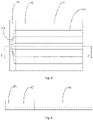
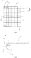
- Fig. 1 is a diagram of a touch screen according to an embodiment of the present invention.
- Fig. 2 is a cross-section view along the line C-C' shown in Fig. 1 .
- the touch screen comprises a flat display area A1, a curved display area A2 and a circuit area B1.
- the curved display area is bended in an arc shape.
- the circuit area B1 is located below the flat display area A1.
- the touch screen 100 further comprises a plurality of touch lines, having signal input ends located in the circuit area B1.
- the touch screen is shown in Fig. 3 and Fig. 4 .
- the one end 21A of the touch line 21 in the circuit area is the signal input end.
- the signal input end 21A is connected to the external driving circuit of the touch screen for implementing the touch function of the touch screen.
- the edge of the display area i.e. the curved display area A2
- the edge of the display area is designed as an arc-shape bending structure. This could move the circuit area B1 connected to the edge of the display area to the area below the display area. In this way, the visual width of the circuit area B1 on the display surface of the touch screen could be reduced.
- the circuit area B1 is right under the flat display area A1. If the central angle ⁇ of the arc-shape curved display area A2 is less than 180 degrees, circuit area B1 is under the flat display area A1 and at a side of the flat display area A1. Specifically, if the central angle ⁇ of the arc-shape curved display area A2 is not less than 90 degrees, the circuit area B1 is right under a display area constituted by the curved display area A2 and the flat display area A1. Thus, the circuit area cannot be observed from the display surface of the touch screen and a visual effect of no-side-frame is achieved.
- the circuit area B1 is under and the curved display area A2 under a display area constituted by the curved display area A2 and the flat display area A1 and at a side of that display area and has an angle with the flat display area A1.
- the visual effect of a narrow-side-frame is achieved.
- a curved radius is also an important parameter to evaluate the bending degree. If the curved radius is greater, the bending degree is higher. In this embodiment, the curved radius should be appropriate, such as 0.5-2 millimeters. This could prevent the pixel circuits and layer structures in the curved display area A2 form being damaged.
- the circuit area B1 could also be bended in addition to the curved display area A2.
- the circuit area B1 could comprise a fan out area B11 and a bonding area B12.
- the fan out area B11 is located between the bonding area B12 and the curved display area A2.
- the fan out area B11 could be bended toward the flat display area A1.
- the signal input ends of the above-mentioned touch lines 12 are all located in the bonding area B12.
- the bonding area B12 could further comprise pins (not shown) for connecting to the external driving circuit.
- the touch lines in the circuit area B1 are gathered together to form a fan shape in the fan out area B11 and the signal input ends of the gathered touch lines 21 are distributed near the pints of the external driving circuit.
- the bonding area B12 can allow a comparatively low bending degree and the fan out area B11 has a better bending performance then the bonding area B12. Therefore, in this embodiment, the fan out area B11 in the circuit area B1 is preferably bended.
- the curved radius of the fan out area B11 is greater than the curved radius of the curved display area A2 such that the bending degree of the fan out B11 is lower than the bending degree of the curved display area.
- the curved radius of the curved display area A2 could be 0.5-2 mm and the curved radius of the fan out area B11 could be 3-5 mm.
- the touch lines 21 could comprise a first touch line 211 and a second touch line 212 crossed each other.
- the first touch line 211 extends through a first predetermined direction in the flat display area A1.
- the second touch line 212 extends through a second predetermined direction in the flat display area A1.
- the first touch line 211 extends through a vertical direction in the flat display area A1 and the second touch line 212 extends through a horizontal direction in the flat display area A1.
- One of the first touch line 211 and the second touch line is a touch driving electrode and the other one is the touch sensing electrode.
- the signal input ends of the first touch line 211 and the second touch line 212 are both in the circuit area B1 to electrically connect to the external driving circuit.
- one end 211A of the first touch line 211 is the signal input end and another end 211B is also a signal input end.
- One end 212A of the second touch line 212 is the signal input end but another end 212B is not the signal input end and located in the flat display area A1.
- the flat display area A1 and the curved display area A2 constitute the display area AA of the touch screen 20.
- the touch screen 20 could further comprise a first circuit area B2 and a second circuit area B3.
- the first circuit area B2 and the second circuit area B3 are oppositely located at two sides of the display area and electrically connected to the circuit area B1.
- the first touch line 211 surrounds a boundary of the display area AA and extends toward the circuit area B1 in the first circuit area B3 and the second circuit area B3.
- the second touch line 212 extends toward the circuit area B1 in the display area AA.
- the first circuit area B2 could be located at the top edge of the display area AA and correspond to the top side frame of the touch screen 20.
- the second circuit area B3 could be located at the bottom edge of the display area AA and correspond to the bottom side frame of the touch screen 20.
- the circuit area B1 could be located at the left edge of the display area AA and correspond to the left side frame of the touch screen 20. Because one end 212B of the second touch line 212, extending horizontally, is in the display area AA and another end 212A is the signal input end and located in the circuit area B1. There is no right side frame of the touch screen 20.
- the left side frame corresponding to the circuit area B1 cannot be visually observed. In this way, there is visually no side frame at the left side and the right side. Furthermore, because the first touch line 211 surrounds the boundary of the display area AA and thus the top side frame and the bottom side frame are smaller and could be ignored. Accordingly, the above touch screen could achieve no-side-frame visual effect.
- the touch screen comprises orderly connected a flat display area, a curved display area and a circuit area.
- the curved display area is in an arc shape.
- the circuit area is below the flat display area.
- the touch screen further comprises a plurality of touch lines, having signal input ends located in the circuit area. Because the edge of the display area is designed as an arc-shape structure, the circuit area connected to the edge area is located under the display area. In this way, the side frame of the display screen could be smaller and thus the screen-to-body ratio could be raised.
- a mobile terminal comprises the touch screen of any one of the above embodiments.
- the touch screen comprises orderly connected a flat display area, a curved display area and a circuit area.
- the curved display area is in an arc shape.
- the circuit area is below the flat display area.
- the touch screen further comprises a plurality of touch lines, having signal input ends located in the circuit area.
- the touch screen because the edge of the display area is designed as an arc-shape structure, the circuit area connected to the edge area is located under the display area. In this way, the side frame of the display screen could be smaller and thus the screen-to-body ratio could be raised.
Landscapes
- Engineering & Computer Science (AREA)
- General Engineering & Computer Science (AREA)
- Theoretical Computer Science (AREA)
- Human Computer Interaction (AREA)
- Physics & Mathematics (AREA)
- General Physics & Mathematics (AREA)
- Computer Networks & Wireless Communication (AREA)
- Devices For Indicating Variable Information By Combining Individual Elements (AREA)
Applications Claiming Priority (2)
| Application Number | Priority Date | Filing Date | Title |
|---|---|---|---|
| CN201910877791.9A CN110688027B (zh) | 2019-09-17 | 2019-09-17 | 一种触控显示屏和移动终端 |
| PCT/CN2019/120208 WO2021051643A1 (zh) | 2019-09-17 | 2019-11-22 | 一种触控显示屏和移动终端 |
Publications (2)
| Publication Number | Publication Date |
|---|---|
| EP4033554A1 true EP4033554A1 (de) | 2022-07-27 |
| EP4033554A4 EP4033554A4 (de) | 2023-09-27 |
Family
ID=69109350
Family Applications (1)
| Application Number | Title | Priority Date | Filing Date |
|---|---|---|---|
| EP19945526.2A Pending EP4033554A4 (de) | 2019-09-17 | 2019-11-22 | Berührungsbildschirm und mobiles endgerät |
Country Status (4)
| Country | Link |
|---|---|
| US (1) | US11747929B2 (de) |
| EP (1) | EP4033554A4 (de) |
| CN (1) | CN110688027B (de) |
| WO (1) | WO2021051643A1 (de) |
Families Citing this family (1)
| Publication number | Priority date | Publication date | Assignee | Title |
|---|---|---|---|---|
| CN114003143B (zh) * | 2021-10-28 | 2024-06-18 | 成都京东方光电科技有限公司 | 触控显示面板和触控显示装置 |
Family Cites Families (20)
| Publication number | Priority date | Publication date | Assignee | Title |
|---|---|---|---|---|
| KR101320384B1 (ko) * | 2011-06-30 | 2013-10-23 | 삼성디스플레이 주식회사 | 가요성 표시 패널 및 상기 가요성 표시 패널을 포함하는 표시 장치 |
| KR101935552B1 (ko) | 2012-06-27 | 2019-04-08 | 삼성디스플레이 주식회사 | 가요성 표시 패널 및 상기 가요성 표시 패널을 포함하는 표시 장치 |
| KR102302811B1 (ko) * | 2013-12-16 | 2021-09-16 | 엘지이노텍 주식회사 | 터치 패널 |
| KR102313990B1 (ko) | 2014-01-29 | 2021-10-18 | 삼성디스플레이 주식회사 | 플렉서블 표시 장치 |
| JP2016188976A (ja) * | 2015-03-30 | 2016-11-04 | 株式会社ジャパンディスプレイ | 表示装置 |
| CN106502442A (zh) * | 2015-09-08 | 2017-03-15 | 宸鸿科技(厦门)有限公司 | 触控显示设备及其制作方法 |
| KR102394723B1 (ko) * | 2015-09-30 | 2022-05-09 | 엘지디스플레이 주식회사 | 터치 스크린 패널 및 이를 포함하는 표시 장치 |
| KR102399297B1 (ko) * | 2016-01-27 | 2022-05-19 | 삼성디스플레이 주식회사 | 터치 패널 및 이를 포함하는 터치 스크린 패널 |
| US10468434B2 (en) | 2016-04-08 | 2019-11-05 | Innolux Corporation | Hybrid thin film transistor structure, display device, and method of making the same |
| US10430000B2 (en) * | 2016-08-05 | 2019-10-01 | Innolux Corporation | Touch display device |
| KR20180032742A (ko) * | 2016-09-22 | 2018-04-02 | 삼성디스플레이 주식회사 | 플렉시블 디스플레이 패널 및 플렉시블 디스플레이 패널 벤딩 방법 |
| JP2018049193A (ja) * | 2016-09-23 | 2018-03-29 | 株式会社ジャパンディスプレイ | 表示装置 |
| CN207082533U (zh) * | 2017-08-22 | 2018-03-09 | 上海和辉光电有限公司 | 一种显示面板及显示装置 |
| EP3644166A4 (de) * | 2017-08-31 | 2020-07-15 | Huawei Technologies Co., Ltd. | Anzeigebildschirm und mobiles endgerät |
| CN109521911B (zh) * | 2017-09-18 | 2022-08-26 | 上海和辉光电股份有限公司 | 一种柔性触控面板及触控显示装置 |
| KR102427667B1 (ko) * | 2017-09-26 | 2022-08-02 | 삼성디스플레이 주식회사 | 디스플레이 장치 |
| CN109559644A (zh) * | 2017-09-27 | 2019-04-02 | 上海和辉光电有限公司 | 一种柔性显示面板及显示装置 |
| KR102588343B1 (ko) * | 2017-10-27 | 2023-10-11 | 엘지디스플레이 주식회사 | 터치 디스플레이 장치 |
| CN108598142B (zh) * | 2018-06-28 | 2020-11-17 | 上海天马微电子有限公司 | 柔性显示基板、柔性显示面板和柔性显示装置 |
| CN109358772B (zh) * | 2018-12-12 | 2021-03-16 | 武汉华星光电半导体显示技术有限公司 | 触摸屏及显示装置 |
-
2019
- 2019-09-17 CN CN201910877791.9A patent/CN110688027B/zh active Active
- 2019-11-22 WO PCT/CN2019/120208 patent/WO2021051643A1/zh not_active Ceased
- 2019-11-22 EP EP19945526.2A patent/EP4033554A4/de active Pending
- 2019-11-22 US US17/615,831 patent/US11747929B2/en active Active
Also Published As
| Publication number | Publication date |
|---|---|
| CN110688027A (zh) | 2020-01-14 |
| US11747929B2 (en) | 2023-09-05 |
| CN110688027B (zh) | 2021-06-15 |
| EP4033554A4 (de) | 2023-09-27 |
| US20220326795A1 (en) | 2022-10-13 |
| WO2021051643A1 (zh) | 2021-03-25 |
Similar Documents
| Publication | Publication Date | Title |
|---|---|---|
| US11624956B2 (en) | Display panel and display device | |
| US10172236B2 (en) | Narrow frame display panel and display | |
| US11195448B2 (en) | Display and mobile terminal | |
| US11092860B1 (en) | Display panel and display device | |
| CN107153492B (zh) | 阵列基板和触控显示面板 | |
| US10739885B2 (en) | Flexible touch panel and display apparatus | |
| US11469257B2 (en) | Display panel and display device | |
| CN107422509B (zh) | 阵列基板、显示面板及显示器 | |
| US11378851B2 (en) | Display panel and display device | |
| EP3229111A1 (de) | Berührungsempfindliches substrat, berührungsbildschirm und anzeigevorrichtung | |
| US11163185B2 (en) | Display device | |
| CN108564886A (zh) | 显示面板和显示装置 | |
| CN205428453U (zh) | 显示装置 | |
| CN111427469B (zh) | 显示面板及显示装置 | |
| US11592918B2 (en) | Flexible touch panel and display apparatus | |
| CN108831299A (zh) | 一种显示面板、显示模组及电子装置 | |
| EP4033554A1 (de) | Berührungsbildschirm und mobiles endgerät | |
| TWI407348B (zh) | 接觸墊陣列 | |
| US10790312B2 (en) | Display panel and display device | |
| US11930597B2 (en) | Display panel and display device having same | |
| US20230205335A1 (en) | Display panel and display device | |
| CN207781091U (zh) | 一种柔性阵列基板及柔性显示装置 | |
| CN110890051A (zh) | 源极驱动装置及显示装置 | |
| US11406017B2 (en) | Flexible printed circuit board, display panel, and display device | |
| CN114120835B (zh) | 显示模组和显示装置 |
Legal Events
| Date | Code | Title | Description |
|---|---|---|---|
| STAA | Information on the status of an ep patent application or granted ep patent |
Free format text: STATUS: THE INTERNATIONAL PUBLICATION HAS BEEN MADE |
|
| PUAI | Public reference made under article 153(3) epc to a published international application that has entered the european phase |
Free format text: ORIGINAL CODE: 0009012 |
|
| STAA | Information on the status of an ep patent application or granted ep patent |
Free format text: STATUS: REQUEST FOR EXAMINATION WAS MADE |
|
| 17P | Request for examination filed |
Effective date: 20220413 |
|
| AK | Designated contracting states |
Kind code of ref document: A1 Designated state(s): AL AT BE BG CH CY CZ DE DK EE ES FI FR GB GR HR HU IE IS IT LI LT LU LV MC MK MT NL NO PL PT RO RS SE SI SK SM TR |
|
| DAV | Request for validation of the european patent (deleted) | ||
| DAX | Request for extension of the european patent (deleted) | ||
| REG | Reference to a national code |
Ref country code: DE Ref legal event code: R079 Free format text: PREVIOUS MAIN CLASS: H01L0051000000 Ipc: G06F0003041000 |
|
| A4 | Supplementary search report drawn up and despatched |
Effective date: 20230829 |
|
| RIC1 | Information provided on ipc code assigned before grant |
Ipc: G06F 3/041 20060101AFI20230823BHEP |