EP4032636B1 - Hochfestes dünnwandiges riffelblech/-band und verfahren zu seiner herstellung - Google Patents
Hochfestes dünnwandiges riffelblech/-band und verfahren zu seiner herstellung Download PDFInfo
- Publication number
- EP4032636B1 EP4032636B1 EP20866406.0A EP20866406A EP4032636B1 EP 4032636 B1 EP4032636 B1 EP 4032636B1 EP 20866406 A EP20866406 A EP 20866406A EP 4032636 B1 EP4032636 B1 EP 4032636B1
- Authority
- EP
- European Patent Office
- Prior art keywords
- strip
- steel plate
- steel
- roll
- gauge
- Prior art date
- Legal status (The legal status is an assumption and is not a legal conclusion. Google has not performed a legal analysis and makes no representation as to the accuracy of the status listed.)
- Active
Links
Images



Classifications
-
- C—CHEMISTRY; METALLURGY
- C21—METALLURGY OF IRON
- C21D—MODIFYING THE PHYSICAL STRUCTURE OF FERROUS METALS; GENERAL DEVICES FOR HEAT TREATMENT OF FERROUS OR NON-FERROUS METALS OR ALLOYS; MAKING METAL MALLEABLE, e.g. BY DECARBURISATION OR TEMPERING
- C21D9/00—Heat treatment, e.g. annealing, hardening, quenching or tempering, adapted for particular articles; Furnaces therefor
- C21D9/52—Heat treatment, e.g. annealing, hardening, quenching or tempering, adapted for particular articles; Furnaces therefor for wires; for strips ; for rods of unlimited length
-
- B—PERFORMING OPERATIONS; TRANSPORTING
- B21—MECHANICAL METAL-WORKING WITHOUT ESSENTIALLY REMOVING MATERIAL; PUNCHING METAL
- B21B—ROLLING OF METAL
- B21B1/00—Metal-rolling methods or mills for making semi-finished products of solid or profiled cross-section; Sequence of operations in milling trains; Layout of rolling-mill plant, e.g. grouping of stands; Succession of passes or of sectional pass alternations
- B21B1/46—Metal-rolling methods or mills for making semi-finished products of solid or profiled cross-section; Sequence of operations in milling trains; Layout of rolling-mill plant, e.g. grouping of stands; Succession of passes or of sectional pass alternations for rolling metal immediately subsequent to continuous casting
-
- B—PERFORMING OPERATIONS; TRANSPORTING
- B21—MECHANICAL METAL-WORKING WITHOUT ESSENTIALLY REMOVING MATERIAL; PUNCHING METAL
- B21B—ROLLING OF METAL
- B21B27/00—Rolls, roll alloys or roll fabrication; Lubricating, cooling or heating rolls while in use
- B21B27/02—Shape or construction of rolls
- B21B27/021—Rolls for sheets or strips
-
- B—PERFORMING OPERATIONS; TRANSPORTING
- B21—MECHANICAL METAL-WORKING WITHOUT ESSENTIALLY REMOVING MATERIAL; PUNCHING METAL
- B21B—ROLLING OF METAL
- B21B37/00—Control devices or methods specially adapted for metal-rolling mills or the work produced thereby
- B21B37/58—Roll-force control; Roll-gap control
-
- B—PERFORMING OPERATIONS; TRANSPORTING
- B21—MECHANICAL METAL-WORKING WITHOUT ESSENTIALLY REMOVING MATERIAL; PUNCHING METAL
- B21B—ROLLING OF METAL
- B21B37/00—Control devices or methods specially adapted for metal-rolling mills or the work produced thereby
- B21B37/74—Temperature control, e.g. by cooling or heating the rolls or the product
-
- B—PERFORMING OPERATIONS; TRANSPORTING
- B21—MECHANICAL METAL-WORKING WITHOUT ESSENTIALLY REMOVING MATERIAL; PUNCHING METAL
- B21B—ROLLING OF METAL
- B21B45/00—Devices for surface or other treatment of work, specially combined with or arranged in, or specially adapted for use in connection with, metal-rolling mills
- B21B45/02—Devices for surface or other treatment of work, specially combined with or arranged in, or specially adapted for use in connection with, metal-rolling mills for lubricating, cooling, or cleaning
-
- B—PERFORMING OPERATIONS; TRANSPORTING
- B21—MECHANICAL METAL-WORKING WITHOUT ESSENTIALLY REMOVING MATERIAL; PUNCHING METAL
- B21B—ROLLING OF METAL
- B21B45/00—Devices for surface or other treatment of work, specially combined with or arranged in, or specially adapted for use in connection with, metal-rolling mills
- B21B45/02—Devices for surface or other treatment of work, specially combined with or arranged in, or specially adapted for use in connection with, metal-rolling mills for lubricating, cooling, or cleaning
- B21B45/0203—Cooling
- B21B45/0209—Cooling devices, e.g. using gaseous coolants
- B21B45/0215—Cooling devices, e.g. using gaseous coolants using liquid coolants, e.g. for sections, for tubes
- B21B45/0233—Spray nozzles, Nozzle headers; Spray systems
-
- B—PERFORMING OPERATIONS; TRANSPORTING
- B21—MECHANICAL METAL-WORKING WITHOUT ESSENTIALLY REMOVING MATERIAL; PUNCHING METAL
- B21H—MAKING PARTICULAR METAL OBJECTS BY ROLLING, e.g. SCREWS, WHEELS, RINGS, BARRELS, BALLS
- B21H8/00—Rolling metal of indefinite length in repetitive shapes specially designed for the manufacture of particular objects, e.g. checkered sheets
- B21H8/005—Embossing sheets or rolls
-
- B—PERFORMING OPERATIONS; TRANSPORTING
- B22—CASTING; POWDER METALLURGY
- B22D—CASTING OF METALS; CASTING OF OTHER SUBSTANCES BY THE SAME PROCESSES OR DEVICES
- B22D11/00—Continuous casting of metals, i.e. casting in indefinite lengths
- B22D11/001—Continuous casting of metals, i.e. casting in indefinite lengths of specific alloys
- B22D11/003—Aluminium alloys
-
- B—PERFORMING OPERATIONS; TRANSPORTING
- B22—CASTING; POWDER METALLURGY
- B22D—CASTING OF METALS; CASTING OF OTHER SUBSTANCES BY THE SAME PROCESSES OR DEVICES
- B22D11/00—Continuous casting of metals, i.e. casting in indefinite lengths
- B22D11/04—Continuous casting of metals, i.e. casting in indefinite lengths into open-ended moulds
- B22D11/055—Cooling the moulds
-
- B—PERFORMING OPERATIONS; TRANSPORTING
- B22—CASTING; POWDER METALLURGY
- B22D—CASTING OF METALS; CASTING OF OTHER SUBSTANCES BY THE SAME PROCESSES OR DEVICES
- B22D11/00—Continuous casting of metals, i.e. casting in indefinite lengths
- B22D11/06—Continuous casting of metals, i.e. casting in indefinite lengths into moulds with travelling walls, e.g. with rolls, plates, belts, caterpillars
- B22D11/0622—Continuous casting of metals, i.e. casting in indefinite lengths into moulds with travelling walls, e.g. with rolls, plates, belts, caterpillars formed by two casting wheels
-
- B—PERFORMING OPERATIONS; TRANSPORTING
- B22—CASTING; POWDER METALLURGY
- B22D—CASTING OF METALS; CASTING OF OTHER SUBSTANCES BY THE SAME PROCESSES OR DEVICES
- B22D21/00—Casting non-ferrous metals or metallic compounds so far as their metallurgical properties are of importance for the casting procedure; Selection of compositions therefor
- B22D21/02—Casting exceedingly oxidisable non-ferrous metals, e.g. in inert atmosphere
- B22D21/04—Casting aluminium or magnesium
-
- C—CHEMISTRY; METALLURGY
- C21—METALLURGY OF IRON
- C21C—PROCESSING OF PIG-IRON, e.g. REFINING, MANUFACTURE OF WROUGHT-IRON OR STEEL; TREATMENT IN MOLTEN STATE OF FERROUS ALLOYS
- C21C5/00—Manufacture of carbon-steel, e.g. plain mild steel, medium carbon steel or cast steel or stainless steel
- C21C5/52—Manufacture of steel in electric furnaces
-
- C—CHEMISTRY; METALLURGY
- C21—METALLURGY OF IRON
- C21D—MODIFYING THE PHYSICAL STRUCTURE OF FERROUS METALS; GENERAL DEVICES FOR HEAT TREATMENT OF FERROUS OR NON-FERROUS METALS OR ALLOYS; MAKING METAL MALLEABLE, e.g. BY DECARBURISATION OR TEMPERING
- C21D1/00—General methods or devices for heat treatment, e.g. annealing, hardening, quenching or tempering
- C21D1/02—Hardening articles or materials formed by forging or rolling, with no further heating beyond that required for the formation
-
- C—CHEMISTRY; METALLURGY
- C21—METALLURGY OF IRON
- C21D—MODIFYING THE PHYSICAL STRUCTURE OF FERROUS METALS; GENERAL DEVICES FOR HEAT TREATMENT OF FERROUS OR NON-FERROUS METALS OR ALLOYS; MAKING METAL MALLEABLE, e.g. BY DECARBURISATION OR TEMPERING
- C21D1/00—General methods or devices for heat treatment, e.g. annealing, hardening, quenching or tempering
- C21D1/56—General methods or devices for heat treatment, e.g. annealing, hardening, quenching or tempering characterised by the quenching agents
- C21D1/60—Aqueous agents
-
- C—CHEMISTRY; METALLURGY
- C21—METALLURGY OF IRON
- C21D—MODIFYING THE PHYSICAL STRUCTURE OF FERROUS METALS; GENERAL DEVICES FOR HEAT TREATMENT OF FERROUS OR NON-FERROUS METALS OR ALLOYS; MAKING METAL MALLEABLE, e.g. BY DECARBURISATION OR TEMPERING
- C21D1/00—General methods or devices for heat treatment, e.g. annealing, hardening, quenching or tempering
- C21D1/56—General methods or devices for heat treatment, e.g. annealing, hardening, quenching or tempering characterised by the quenching agents
- C21D1/613—Gases; Liquefied or solidified normally gaseous material
-
- C—CHEMISTRY; METALLURGY
- C21—METALLURGY OF IRON
- C21D—MODIFYING THE PHYSICAL STRUCTURE OF FERROUS METALS; GENERAL DEVICES FOR HEAT TREATMENT OF FERROUS OR NON-FERROUS METALS OR ALLOYS; MAKING METAL MALLEABLE, e.g. BY DECARBURISATION OR TEMPERING
- C21D1/00—General methods or devices for heat treatment, e.g. annealing, hardening, quenching or tempering
- C21D1/62—Quenching devices
- C21D1/667—Quenching devices for spray quenching
-
- C—CHEMISTRY; METALLURGY
- C21—METALLURGY OF IRON
- C21D—MODIFYING THE PHYSICAL STRUCTURE OF FERROUS METALS; GENERAL DEVICES FOR HEAT TREATMENT OF FERROUS OR NON-FERROUS METALS OR ALLOYS; MAKING METAL MALLEABLE, e.g. BY DECARBURISATION OR TEMPERING
- C21D1/00—General methods or devices for heat treatment, e.g. annealing, hardening, quenching or tempering
- C21D1/74—Methods of treatment in inert gas, controlled atmosphere, vacuum or pulverulent material
- C21D1/76—Adjusting the composition of the atmosphere
-
- C—CHEMISTRY; METALLURGY
- C21—METALLURGY OF IRON
- C21D—MODIFYING THE PHYSICAL STRUCTURE OF FERROUS METALS; GENERAL DEVICES FOR HEAT TREATMENT OF FERROUS OR NON-FERROUS METALS OR ALLOYS; MAKING METAL MALLEABLE, e.g. BY DECARBURISATION OR TEMPERING
- C21D6/00—Heat treatment of ferrous alloys
- C21D6/005—Heat treatment of ferrous alloys containing Mn
-
- C—CHEMISTRY; METALLURGY
- C21—METALLURGY OF IRON
- C21D—MODIFYING THE PHYSICAL STRUCTURE OF FERROUS METALS; GENERAL DEVICES FOR HEAT TREATMENT OF FERROUS OR NON-FERROUS METALS OR ALLOYS; MAKING METAL MALLEABLE, e.g. BY DECARBURISATION OR TEMPERING
- C21D6/00—Heat treatment of ferrous alloys
- C21D6/008—Heat treatment of ferrous alloys containing Si
-
- C—CHEMISTRY; METALLURGY
- C21—METALLURGY OF IRON
- C21D—MODIFYING THE PHYSICAL STRUCTURE OF FERROUS METALS; GENERAL DEVICES FOR HEAT TREATMENT OF FERROUS OR NON-FERROUS METALS OR ALLOYS; MAKING METAL MALLEABLE, e.g. BY DECARBURISATION OR TEMPERING
- C21D8/00—Modifying the physical properties of ferrous metals or ferrous alloys by deformation combined with, or followed by, heat treatment
- C21D8/02—Modifying the physical properties of ferrous metals or ferrous alloys by deformation combined with, or followed by, heat treatment during manufacturing of plates or strips
-
- C—CHEMISTRY; METALLURGY
- C21—METALLURGY OF IRON
- C21D—MODIFYING THE PHYSICAL STRUCTURE OF FERROUS METALS; GENERAL DEVICES FOR HEAT TREATMENT OF FERROUS OR NON-FERROUS METALS OR ALLOYS; MAKING METAL MALLEABLE, e.g. BY DECARBURISATION OR TEMPERING
- C21D8/00—Modifying the physical properties of ferrous metals or ferrous alloys by deformation combined with, or followed by, heat treatment
- C21D8/02—Modifying the physical properties of ferrous metals or ferrous alloys by deformation combined with, or followed by, heat treatment during manufacturing of plates or strips
- C21D8/021—Modifying the physical properties of ferrous metals or ferrous alloys by deformation combined with, or followed by, heat treatment during manufacturing of plates or strips involving particular fabrication steps or treatments of ingots or slabs
- C21D8/0215—Rapid solidification; Thin strip casting
-
- C—CHEMISTRY; METALLURGY
- C21—METALLURGY OF IRON
- C21D—MODIFYING THE PHYSICAL STRUCTURE OF FERROUS METALS; GENERAL DEVICES FOR HEAT TREATMENT OF FERROUS OR NON-FERROUS METALS OR ALLOYS; MAKING METAL MALLEABLE, e.g. BY DECARBURISATION OR TEMPERING
- C21D8/00—Modifying the physical properties of ferrous metals or ferrous alloys by deformation combined with, or followed by, heat treatment
- C21D8/02—Modifying the physical properties of ferrous metals or ferrous alloys by deformation combined with, or followed by, heat treatment during manufacturing of plates or strips
- C21D8/0221—Modifying the physical properties of ferrous metals or ferrous alloys by deformation combined with, or followed by, heat treatment during manufacturing of plates or strips characterised by the working steps
- C21D8/0226—Hot rolling
-
- C—CHEMISTRY; METALLURGY
- C21—METALLURGY OF IRON
- C21D—MODIFYING THE PHYSICAL STRUCTURE OF FERROUS METALS; GENERAL DEVICES FOR HEAT TREATMENT OF FERROUS OR NON-FERROUS METALS OR ALLOYS; MAKING METAL MALLEABLE, e.g. BY DECARBURISATION OR TEMPERING
- C21D8/00—Modifying the physical properties of ferrous metals or ferrous alloys by deformation combined with, or followed by, heat treatment
- C21D8/02—Modifying the physical properties of ferrous metals or ferrous alloys by deformation combined with, or followed by, heat treatment during manufacturing of plates or strips
- C21D8/0247—Modifying the physical properties of ferrous metals or ferrous alloys by deformation combined with, or followed by, heat treatment during manufacturing of plates or strips characterised by the heat treatment
- C21D8/0263—Modifying the physical properties of ferrous metals or ferrous alloys by deformation combined with, or followed by, heat treatment during manufacturing of plates or strips characterised by the heat treatment following hot rolling
-
- C—CHEMISTRY; METALLURGY
- C21—METALLURGY OF IRON
- C21D—MODIFYING THE PHYSICAL STRUCTURE OF FERROUS METALS; GENERAL DEVICES FOR HEAT TREATMENT OF FERROUS OR NON-FERROUS METALS OR ALLOYS; MAKING METAL MALLEABLE, e.g. BY DECARBURISATION OR TEMPERING
- C21D9/00—Heat treatment, e.g. annealing, hardening, quenching or tempering, adapted for particular articles; Furnaces therefor
- C21D9/52—Heat treatment, e.g. annealing, hardening, quenching or tempering, adapted for particular articles; Furnaces therefor for wires; for strips ; for rods of unlimited length
- C21D9/54—Furnaces for treating strips or wire
- C21D9/56—Continuous furnaces for strip or wire
- C21D9/573—Continuous furnaces for strip or wire with cooling
-
- C—CHEMISTRY; METALLURGY
- C22—METALLURGY; FERROUS OR NON-FERROUS ALLOYS; TREATMENT OF ALLOYS OR NON-FERROUS METALS
- C22C—ALLOYS
- C22C33/00—Making ferrous alloys
- C22C33/04—Making ferrous alloys by melting
-
- C—CHEMISTRY; METALLURGY
- C22—METALLURGY; FERROUS OR NON-FERROUS ALLOYS; TREATMENT OF ALLOYS OR NON-FERROUS METALS
- C22C—ALLOYS
- C22C33/00—Making ferrous alloys
- C22C33/04—Making ferrous alloys by melting
- C22C33/06—Making ferrous alloys by melting using master alloys
-
- C—CHEMISTRY; METALLURGY
- C22—METALLURGY; FERROUS OR NON-FERROUS ALLOYS; TREATMENT OF ALLOYS OR NON-FERROUS METALS
- C22C—ALLOYS
- C22C38/00—Ferrous alloys, e.g. steel alloys
- C22C38/001—Ferrous alloys, e.g. steel alloys containing N
-
- C—CHEMISTRY; METALLURGY
- C22—METALLURGY; FERROUS OR NON-FERROUS ALLOYS; TREATMENT OF ALLOYS OR NON-FERROUS METALS
- C22C—ALLOYS
- C22C38/00—Ferrous alloys, e.g. steel alloys
- C22C38/002—Ferrous alloys, e.g. steel alloys containing In, Mg, or other elements not provided for in one single group C22C38/001 - C22C38/60
-
- C—CHEMISTRY; METALLURGY
- C22—METALLURGY; FERROUS OR NON-FERROUS ALLOYS; TREATMENT OF ALLOYS OR NON-FERROUS METALS
- C22C—ALLOYS
- C22C38/00—Ferrous alloys, e.g. steel alloys
- C22C38/008—Ferrous alloys, e.g. steel alloys containing tin
-
- C—CHEMISTRY; METALLURGY
- C22—METALLURGY; FERROUS OR NON-FERROUS ALLOYS; TREATMENT OF ALLOYS OR NON-FERROUS METALS
- C22C—ALLOYS
- C22C38/00—Ferrous alloys, e.g. steel alloys
- C22C38/02—Ferrous alloys, e.g. steel alloys containing silicon
-
- C—CHEMISTRY; METALLURGY
- C22—METALLURGY; FERROUS OR NON-FERROUS ALLOYS; TREATMENT OF ALLOYS OR NON-FERROUS METALS
- C22C—ALLOYS
- C22C38/00—Ferrous alloys, e.g. steel alloys
- C22C38/04—Ferrous alloys, e.g. steel alloys containing manganese
-
- C—CHEMISTRY; METALLURGY
- C22—METALLURGY; FERROUS OR NON-FERROUS ALLOYS; TREATMENT OF ALLOYS OR NON-FERROUS METALS
- C22C—ALLOYS
- C22C38/00—Ferrous alloys, e.g. steel alloys
- C22C38/06—Ferrous alloys, e.g. steel alloys containing aluminium
-
- C—CHEMISTRY; METALLURGY
- C22—METALLURGY; FERROUS OR NON-FERROUS ALLOYS; TREATMENT OF ALLOYS OR NON-FERROUS METALS
- C22C—ALLOYS
- C22C38/00—Ferrous alloys, e.g. steel alloys
- C22C38/16—Ferrous alloys, e.g. steel alloys containing copper
-
- B—PERFORMING OPERATIONS; TRANSPORTING
- B21—MECHANICAL METAL-WORKING WITHOUT ESSENTIALLY REMOVING MATERIAL; PUNCHING METAL
- B21B—ROLLING OF METAL
- B21B1/00—Metal-rolling methods or mills for making semi-finished products of solid or profiled cross-section; Sequence of operations in milling trains; Layout of rolling-mill plant, e.g. grouping of stands; Succession of passes or of sectional pass alternations
- B21B1/46—Metal-rolling methods or mills for making semi-finished products of solid or profiled cross-section; Sequence of operations in milling trains; Layout of rolling-mill plant, e.g. grouping of stands; Succession of passes or of sectional pass alternations for rolling metal immediately subsequent to continuous casting
- B21B1/463—Metal-rolling methods or mills for making semi-finished products of solid or profiled cross-section; Sequence of operations in milling trains; Layout of rolling-mill plant, e.g. grouping of stands; Succession of passes or of sectional pass alternations for rolling metal immediately subsequent to continuous casting in a continuous process, i.e. the cast not being cut before rolling
-
- B—PERFORMING OPERATIONS; TRANSPORTING
- B21—MECHANICAL METAL-WORKING WITHOUT ESSENTIALLY REMOVING MATERIAL; PUNCHING METAL
- B21B—ROLLING OF METAL
- B21B27/00—Rolls, roll alloys or roll fabrication; Lubricating, cooling or heating rolls while in use
- B21B27/005—Rolls with a roughened or textured surface; Methods for making same
-
- B—PERFORMING OPERATIONS; TRANSPORTING
- B29—WORKING OF PLASTICS; WORKING OF SUBSTANCES IN A PLASTIC STATE IN GENERAL
- B29C—SHAPING OR JOINING OF PLASTICS; SHAPING OF MATERIAL IN A PLASTIC STATE, NOT OTHERWISE PROVIDED FOR; AFTER-TREATMENT OF THE SHAPED PRODUCTS, e.g. REPAIRING
- B29C59/00—Surface shaping of articles, e.g. embossing; Apparatus therefor
- B29C59/02—Surface shaping of articles, e.g. embossing; Apparatus therefor by mechanical means, e.g. pressing
- B29C59/04—Surface shaping of articles, e.g. embossing; Apparatus therefor by mechanical means, e.g. pressing using rollers or endless belts
-
- C—CHEMISTRY; METALLURGY
- C21—METALLURGY OF IRON
- C21D—MODIFYING THE PHYSICAL STRUCTURE OF FERROUS METALS; GENERAL DEVICES FOR HEAT TREATMENT OF FERROUS OR NON-FERROUS METALS OR ALLOYS; MAKING METAL MALLEABLE, e.g. BY DECARBURISATION OR TEMPERING
- C21D2211/00—Microstructure comprising significant phases
- C21D2211/005—Ferrite
-
- C—CHEMISTRY; METALLURGY
- C21—METALLURGY OF IRON
- C21D—MODIFYING THE PHYSICAL STRUCTURE OF FERROUS METALS; GENERAL DEVICES FOR HEAT TREATMENT OF FERROUS OR NON-FERROUS METALS OR ALLOYS; MAKING METAL MALLEABLE, e.g. BY DECARBURISATION OR TEMPERING
- C21D2211/00—Microstructure comprising significant phases
- C21D2211/009—Pearlite
-
- C—CHEMISTRY; METALLURGY
- C21—METALLURGY OF IRON
- C21D—MODIFYING THE PHYSICAL STRUCTURE OF FERROUS METALS; GENERAL DEVICES FOR HEAT TREATMENT OF FERROUS OR NON-FERROUS METALS OR ALLOYS; MAKING METAL MALLEABLE, e.g. BY DECARBURISATION OR TEMPERING
- C21D2261/00—Machining or cutting being involved
-
- Y—GENERAL TAGGING OF NEW TECHNOLOGICAL DEVELOPMENTS; GENERAL TAGGING OF CROSS-SECTIONAL TECHNOLOGIES SPANNING OVER SEVERAL SECTIONS OF THE IPC; TECHNICAL SUBJECTS COVERED BY FORMER USPC CROSS-REFERENCE ART COLLECTIONS [XRACs] AND DIGESTS
- Y02—TECHNOLOGIES OR APPLICATIONS FOR MITIGATION OR ADAPTATION AGAINST CLIMATE CHANGE
- Y02P—CLIMATE CHANGE MITIGATION TECHNOLOGIES IN THE PRODUCTION OR PROCESSING OF GOODS
- Y02P10/00—Technologies related to metal processing
- Y02P10/20—Recycling
Definitions
- the present invention pertains to continuous casting processes and products in the metallurgical industry, in particular to a high-strength thin-gauge checkered steel plate/strip and a manufacturing method therefor.
- tin (Sn) and copper (Cu) are typical residual elements or harmful elements in steel. It is very difficult and expensive to remove Sn and Cu fully during the steelmaking process. Generally, once the steel contains Sn and Cu, they cannot be eliminated thoroughly. Instead, the contents of Sn and Cu can only be reduced by diluting molten steel, which leads to an increased smelting cost for steel products.
- Traditional thin strip steel is mostly produced by multi-pass continuous rolling of a cast slab having a thickness of 70-200 mm.
- the traditional hot rolling process is: continuous casting + cast slab reheating and heat preservation + rough rolling + finish rolling + cooling + coiling.
- a cast slab having a thickness of about 200 mm is firstly obtained by continuous casting; the cast slab is reheated and held; then, rough rolling and finish rolling are performed to obtain a steel strip having a thickness generally greater than 2 mm; and finally, laminar cooling and coiling are performed on the steel strip to complete the entire hot rolling production process.
- the thin slab continuous casting and rolling process flow is: continuous casting + heat preservation and soaking of the cast slab + hot continuous rolling + cooling + coiling.
- the main differences between this process and the traditional process are as follows: the thickness of the cast slab in the thin slab process is greatly reduced to 50-90 mm. Because the cast slab is thin, the cast slab only needs to undergo 1-2 passes of rough rolling (when the thickness of the cast slab is 70-90 mm), or does not need to undergo rough rolling (when the thickness of the slab is 50 mm). In contrast, the continuous casting slab in the traditional process needs to be rolled repeatedly for multiple passes before it can be thinned to the required gauge before finish rolling.
- the cast slab in the thin slab process does not undergo cooling, but enters a soaking furnace directly for soaking and heat preservation, or a small amount of heat is supplemented.
- the thin slab process greatly shortens the process flow, reduces energy consumption, reduces investment, and thus reduces production cost.
- the thin slab continuous casting and rolling process increases the steel strength and yield ratio, thereby increasing the rolling load, so that the thickness gauge of the hot-rolled products that can be economically produced cannot be too thin, generally ⁇ 1.5mm. See Chinese patents CN200610123458.1 , CN200610035800.2 and CN200710031548.2 .
- Sn and Cu elements are not involved in these patent applications.
- the endless thin slab continuous casting and rolling process (ESP in short) rising in recent years is an improved process developed on the basis of the above semi-endless thin slab continuous casting and rolling process.
- the ESP realizes endless rolling for continuous casting of a slab, and eliminates the flame cutting of the slab and the heating furnace that is used for heat preservation, soaking and transition of slabs.
- the length of the entire production line is greatly shortened to about 190 meters.
- the slab produced by continuous casting with a continuous casting machine has a thickness of 90-110 mm and a width of 1100-1600 mm.
- the slab produced by continuous casting passes through an induction heating roll table to effect heat preservation and soaking on the slab. Then, the slab enters the rough rolling, finish rolling, laminar cooling, and coiling processes to obtain a hot-rolled plate.
- the thin strip continuous casting and rolling process has a shorter process flow than the thin slab continuous casting and rolling.
- the thin strip continuous casting technology is a cutting-edge technology in the research field of metallurgy and materials. Its appearance brings about a revolution to the steel industry. It changes the production process of steel strip in the traditional metallurgical industry by integrating continuous casting, rolling, and even heat treatment, so that the thin strip blank produced can be formed into a thin steel strip at one time after one pass of online hot rolling. Thus, the production process is simplified greatly, the production cycle is shortened, and the length of the process line is only about 50 m. The equipment investment is also reduced accordingly, and the product cost is significantly reduced. It is a low-carbon, environmentally friendly process for producing a hot-rolled thin strip.
- the twin-roll thin strip continuous casting process is the main form of the thin strip continuous casting process, and it is also the only thin strip continuous casting process that has been industrialized in the world.
- FIG. 1 A typical process flow of twin-roll thin strip continuous casting is shown by Fig. 1 .
- the molten steel in a ladle 1 passes through a ladle shroud 2, a tundish 3, a submerged nozzle 4 and a distributor 5, and is then directly poured into a molten pool 7 formed with side sealing devices 6a, 6b and two counter-rotating crystallization rolls 8a, 8b capable of rapid cooling.
- the molten steel solidifies on the circumferential surfaces of the rotating crystallization rolls 8a, 8b to form a solidified shell which gradually grows, and then forms a 1-5 mm thick cast strip 11 at the minimum gap (nip point) between the two crystallization rolls.
- the cast strip 11 is guided by a guide plate 9 to pinch rolls 12 and sent to a rolling mill 13 to be rolled into a thin strip of 0.7-2.5 mm, and then cooled by a cooling device 14. After its head is cut off by a flying shear 16, it is finally sent to a coiler 19 to be coiled into a coil.
- Checkered plate is a hot-rolled steel plate with a pattern on its surface.
- As a special hot-rolled plate/strip product it is widely used in construction, machinery manufacturing, automobiles, bridges, transportation, shipbuilding and other fields. Its market demand is relatively high. Especially, the market demand for thin-gauge checkered plates is higher. Because extremely thin gauge ( ⁇ 1.5mm) checkered plates impose high requirements on the rolling stability of a rolling mill and the coiling shape of a coiler, they can be produced only by a few domestic manufacturers.
- the market price of the thin-gauge hot-rolled checkered plates is higher than the price of the hot-rolled checkered plates having a thickness of 2.0 mm or more by 120-200 Yuan/ton.
- the main product types include checkered plate with round bean pattern, checkered plate with diamond pattern and checkered plate with lentil pattern.
- the checkered plate with lentil pattern has the characteristics of wear resistance, beautiful appearance, slip resistance, oil and water repellency, good cleanability, and less consumption of steel. So, the lentil pattern has become the mainstream pattern on checkered plates.
- the checkered plate with lentil pattern has a good number of application scenarios, a large market demand and a high price, and has become a high value-added variety and a typical product of hot continuous rolling enterprises. The major steel plants are competing for development and production of this type of plate.
- the contact of the high-temperature strip steel with the cooling water may also cause many problems: first, water spots (rust spots) may be formed on the surface of the strip steel, which will affect the surface quality; second, cooling water for laminar cooling or spray cooling tends to cause local uneven cooling on the surface of the strip steel, resulting in a non-uniform microstructure inside the strip steel, so that the properties of the strip steel are not uniform and the product quality is affected; third, the local uneven cooling on the surface of the strip steel may cause deterioration of the strip shape, which affects the shape quality.
- water spots rust spots
- cooling water for laminar cooling or spray cooling tends to cause local uneven cooling on the surface of the strip steel, resulting in a non-uniform microstructure inside the strip steel, so that the properties of the strip steel are not uniform and the product quality is affected
- third, the local uneven cooling on the surface of the strip steel may cause deterioration of the strip shape, which affects the shape quality.
- the steel produced by this process generally has problems such as nonuniform structure, low elongation, high yield ratio and poor formability.
- the austenite grains in the cast strip are obviously not uniform, such that the structure of the final product obtained after austenite transformation is not uniform, either.
- the properties of the product are not stable. Therefore, it is difficult and challenging to use a thin strip continuous casting production line to produce high-strength, thin-gauge checkered plates. It is impossible to produce them by copying the traditional composition and process. Instead, a breakthrough in composition and process is required.
- EP 1 254 275 A1 discloses a steel product comprising 0.03 to 0.17% C, 0.01 to 0.5% Si, 0.4 to 2.0 % Mn, 0.005 to 0.2% Ti, 0.0005 to 0.1% Al, 0.001 to 0.03% Zr, 0.008 to 0.030% N, 0.0003 to 0.01% B, 0.001 to 0.2% W, at most 0.03% P, at most 0.03% S, at most 0.01% O, and balance Fe, and having a microstructure essentially consisting of a complex structure of ferrite and pearlite having a grain size of 20 ⁇ m or less.
- US 2014/366602 A1 describes a manufacturing method for continuous strip cast weather-resistant steel having a high-strength of 700 MPa-grade.
- One object of the present invention is to provide a high-strength thin-gauge checkered steel plate/strip and a manufacturing method therefor, wherein a twin-roll thin strip continuous casting process is employed for the production with full use of the residual harmful elements such as Sn, Cu and the like in steel scrap to achieve comprehensive utilization of steel scrap resources, and complicated intermediate processes such as slab heating, multi-pass repeated hot rolling and the like may be obviated.
- a twin-roll thin strip continuous casting + one-pass on-line hot rolling process the production process is shorter, the efficiency is higher, and the investment cost for the production line and the production cost are reduced significantly.
- the hot-rolled high-strength thin-gauge checkered steel plate/strip produced by the process according to the present invention does not need to be further rolled. It can be marketed directly for use. The cost-effectiveness of plate and strip is improved significantly. It can be widely used in construction, machinery manufacturing, automobiles, bridges, transportation, shipbuilding and other fields.
- the technical solution of the present invention provides a high-strength thin-gauge checkered steel plate/strip as defined in claim 1 and a manufacturing method for the same as defined in claim 5. Further improvements are subject to the dependent claims.
- residual elements such as Sn and Cu in steel scrap are used as alloy elements for smelting to produce molten steel, and micro-alloy elements such as B are selectively added to the steel.
- the basicity for slagging, the type and melting point of the inclusions in the steel, the free oxygen content in the molten steel, and the content of acid-soluble aluminum Als are controlled.
- twin-roll thin strip continuous casting is performed to cast a strip steel having a thickness of 1.5-3 mm. After the strip steel exits crystallization rolls, it directly enters a lower closed chamber having a non-oxidizing atmosphere, and enters an on-line rolling mill for hot rolling under closed conditions.
- the rolled strip steel is cooled by gas atomization cooling.
- the gas atomization cooling can effectively reduce the thickness of the oxide scale on the surface of the strip steel, increase the temperature uniformity of the strip steel, and improve the surface quality of the strip.
- the final steel coil produced can be used directly as a hot rolled checkered plate/strip, or as a finished checkered plate/strip after trimming-flattening.
- the high-strength thin-gauge checkered steel plate/strip according to the present invention comprises the following chemical elements in weight percentages: C: ⁇ 0.06%, Si: ⁇ 0.5%, Mn: 0.4-1.7%, P ⁇ 0.04%, S ⁇ 0.007%, N: 0.004-0.010%, Als: ⁇ 0.001%, B: 0.001-0.006%, Mn/S ⁇ 250, total oxygen [O] T : 0.007-0.020%; also Cu: 0.1-0.6% and/or Sn: 0.005-0.04%; and a balance of Fe and other unavoidable impurities.
- the checkered steel plate/strip according to the present invention has a yield strength of ⁇ 345 MPa, a tensile strength of ⁇ 470 MPa, and an elongation of ⁇ 22% and has a thickness of 0.8-2.5 mm.
- the checkered steel plate/strip according to the present invention further has a pattern height h of at least 20% of a thickness a of a base plate/strip, i.e., h ⁇ 0.2a.
- the high-strength thin-gauge checkered steel plate/strip according to the present invention comprises the following chemical elements in weight percentages: C: 0.02-0.06%, Si: 0.1-0.5%, Mn: 0.4-1.7%, P ⁇ 0.04%, S ⁇ 0.007%, N: 0.004-0.010%, Als: ⁇ 0.001%, B: 0.001-0.006%, Mn/S ⁇ 250, any one or both of Cu: 0.1-0.6% and Sn: 0.005-0.04%, total oxygen [O] T : 0.007-0.020%; and a balance of Fe and other unavoidable impurities.
- the structure of the checkered steel plate/strip according to the present invention may be a mixed microstructure of acicular ferrite + pearlite.
- Mn / S > 250 .
- the checkered steel plate/strip has a thickness of 1.0-1.6 mm.
- C is the most economical and basic strengthening element in the steel. It increases the steel strength by solid solution strengthening and precipitation strengthening. C is an essential element for precipitation of cementite during austenite transformation. Hence, the level of C content largely determines the strength level of the steel. That is, a higher C content leads to a higher strength level. However, since the interstitial solid solution and precipitation of C do great harm to the plasticity and toughness of the steel, and an unduly high C content is unfavorable to the welding performance, the C content cannot be too high.
- the steel strength is compensated by appropriate addition of an alloy element(s).
- Si plays a role in solid solution strengthening in the steel, and the addition of Si to the steel can improve steel purity and fulfill deoxygenation. However, an unduly high content of Si will deteriorate weldability and toughness of the welding heat affected zone. Hence, the content of Si used according to the present invention is in the range of ⁇ 0.5%. In some embodiments, the content of Si is in the range of 0.1-0.5%.
- Mn is one of the cheapest alloy elements. It can improve the hardenability of the steel. It has a considerable solid solubility in the steel, and increases the steel strength by solid solution strengthening with substantially no damage to the plasticity or toughness of the steel. It is the most important strengthening element to improve the steel strength, and it can also play a role in deoxygenation in the steel. However, an unduly high content of Mn will deteriorate weldability and toughness of the welding heat affected zone. Hence, the content of Mn used according to the present invention is in the range of 0.4-1.7%.
- S is a harmful element in the steel. Particularly, it introduces hot shortness to the steel, reduces the ductility and toughness of the steel, and causes cracks during rolling. S also reduces weldability and corrosion resistance. Therefore, according to the present invention, S is also controlled as an impurity element, and its content is in the range of ⁇ 0.007%; in some embodiments, in the range of ⁇ 0.0067%.
- N element can improve the steel strength by interstitial solid solution.
- a certain amount of N needs to exist in the steel because the interaction of N and B is necessary in the steel to generate a precipitation phase of BN.
- the interstitial solid solution of N harms the plasticity and toughness of the steel to a relatively large extent, and the existence of free N may increase the yield ratio of the steel.
- the N content should not be too high.
- the content of N used according to the present invention is in the range of 0.004-0.010%.
- Cu mainly plays a role in solid solution strengthening and precipitation strengthening in the steel. Since Cu is an element prone to segregation, the content of Cu is generally controlled strictly in the traditional process. In view of the rapid solidification effect of thin strip continuous casting, the upper limit of Cu is increased to 0.60% according to the present invention. In a certain sense, the increased Cu content can realize effective utilization of copper in steel scrap or poor quality mineral resources (high-copper ore), promote the recycling of steel, reduce production cost, and achieve the purpose of sustainable development. In some embodiments, the content of Cu, if present, is in the range of 0. 1-0.6%.
- Sn element is also one of the main residual elements in steel scrap. It is recognized as a harmful element in steel. Because Sn is an element prone to segregation, Sn even in a small amount may be enriched at the grain boundary, resulting in defects such as cracks. Therefore, the content of Sn element is strictly controlled in the traditional process. Because thin strip continuous casting has the characteristic of rapid solidification, interdendritic segregation of an element is greatly reduced. As a result, the solid solubility of the element can be increased greatly. Therefore, under the conditions of the thin strip continuous casting process, the content range of Sn element can be expanded, and the steelmaking cost can thus be reduced greatly.
- Fig. 2 shows the relationship between Sn element and average heat flux. It can be seen from Fig.
- Fig. 3 shows the relationship between Sn content and surface roughness. Because cracks on the surface of a cast strip are usually generated at the uneven folds on the surface of the cast strip, surface roughness is used to characterize the occurrence of the surface cracks. If the roughness is large, the probability of cracking is high. It can be seen from Fig. 3 that the increase of the Sn content has no adverse influence on the surface quality of the cast strip under the condition of rapid solidification. As it can be seen from the results in Figs. 2 and 3 , Sn has no adverse influence on the solidification and surface quality of the cast strip. Therefore, according to the present invention, the limitation to the Sn content may be further relaxed, and the designed Sn content is in the range of 0.005-0.04%.
- B The notable role of B in the steel is that a minute amount of B can multiply the hardenability of the steel.
- B may allow for preferential precipitation of coarse BN particles in high-temperature austenite, thereby inhibiting precipitation of fine AlN, weakening the pinning effect of the fine AlN on the grain boundary, and promoting the growth ability of grains.
- austenite grains are coarsened and homogenized. This is beneficial to recrystallization after rolling. The coarsening and homogenization of austenite grains further helps to improve the yield ratio of the product and improve the formability of the product.
- the combination of B and N can effectively prevent appearance of the low melting point phase B 2 O 3 at the grain boundary.
- B is an active element that is prone to segregation, and it tends to segregate at the grain boundary.
- the B content is generally controlled very strictly, usually around 0.001-0.003%.
- the solidification and cooling rate is fast.
- the segregation of B can be inhibited effectively, and more B can be solid dissolved. Therefore, the limitation to the B content can be relaxed appropriately.
- Coarse BN particles can also be produced by controlling the process appropriately to inhibit precipitation of fine AlN. In this way, B plays a role in nitrogen fixation. Therefore, a higher B content is used in the present invention than in the traditional process, and the range is 0.001-0.006%.
- a manufacturing method for the high-strength thin-gauge checkered steel plate/strip according to the present invention comprises the following steps:
- an electric furnace is used for smelting to produce molten steel, wherein 100% steel scrap may be selected as the raw material for smelting without pre-screening.
- a converter is used for smelting to produce molten steel, wherein steel scrap is added to the converter in an amount of 20% of the raw material for smelting without pre-screening. Then, the molten steel is delivered to an LF furnace, VD/VOD furnace or RH furnace for refining.
- the non-oxidizing gas includes an inert gas, N 2 , or a mixed gas of CO 2 gas produced by sublimation of dry ice, N 2 and H 2 .
- rolls used for producing the checkered steel plate/strip by rolling include an upper roll and a lower roll, wherein the upper roll is an embossed roll, and the lower roll is a flat roll; wherein the upper embossed roll has a roll diameter that is 0.3-3 mm larger than a roll diameter of the lower flat roll.
- the lower flat roll has a roll diameter at a center of the lower flat roll that is 0.15-0.22 mm smaller than roll diameters at both ends, and a parabolic roll shape with smooth transition from the center to both of the ends is formed.
- the gas atomization cooling utilizes a gas-water ratio of 15:1-10:1, a gas pressure of 0.5-0.8 MPa, and a water pressure of 1.0-1.5 MPa.
- the gas-water ratio refers to the flow ratio of compressed air to water, and the unit of the flow is m 3 /h.
- step 5 1-2 pairs of high-pressure lateral jet nozzles are operated at an outlet where the checkered steel plate/strip comes out after atomization cooling to purge water accumulated on a surface of the checkered steel plate/strip, wherein a nozzle pressure is 0.5-0.8 MPa, and a flow rate is 20-200 m 3 /h.
- the coiling utilizes double-coiler coiling or Carrousel coiling.
- the steel scrap raw materials Due to the need to control the steel composition, there are certain quality requirements for the steel scrap raw materials to be used. Generally, the steel scrap needs to be pre-screened and classified.
- some domestic electric furnace steel plants choose to add concentrates such as purchased sponge iron, iron carbide and the like to the raw material composition to dilute the harmful elements that are difficult to be removed from the steel scrap, and thus improve the quality of the molten steel.
- Some domestic steel plants that have both a blast furnace and an electric furnace add self-produced molten iron into the electric furnace as a raw material in the electric furnace to improve the production efficiency of the electric furnace, thereby shortening the tapping time of the electric furnace greatly.
- the blending ratio of the molten iron in the electric furnace can reach 30-50%.
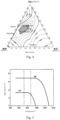
- MnO-SiO 2 -Al 2 O 3 ternary inclusion In order to improve the castability of the molten steel for thin strip continuous casting, it is necessary to obtain a low-melting-point MnO-SiO 2 -Al 2 O 3 ternary inclusion, as shown in the shaded area in Fig. 4 .
- the MnO/SiO 2 (mass ratio) in the MnO-SiO 2 -Al 2 O 3 ternary inclusion is controlled at 0.5-2, preferably 1-1.8.
- O is an essential element to form an oxide inclusion in the steel. Since it's necessary to form the low-melting-point MnO-SiO 2 -Al 2 O 3 ternary inclusion according to the present invention, the free oxygen [O] Free is required to be in the range of 0.0005-0.005%.
- Mn and S In order to improve the castability of the molten steel for thin strip continuous casting, among the above components, Mn and S must be controlled to satisfy the following relationship: Mn/S ⁇ 250.
- the cast strip After the cast strip leaves the crystallization rolls, the cast strip has a temperature of 1420-1480 °C, and it enters the lower closed chamber directly.
- the lower closed chamber is supplied with a non-oxidizing gas to provide anti-oxidation protection to the strip steel.
- the anti-oxidation protection provided by the lower closed chamber to the cast strip extends to the inlet of the rolling mill.
- the temperature of the cast strip at the outlet of the lower closed chamber is 1150-1300°C.
- the temperature at which BN begins to precipitate in the steel is around 1280 °C, and the precipitation of BN levels off at 980 °C, while the precipitation of AlN has just begun (the temperature at which AlN begins to precipitate is around 980 °C).
- the precipitation of BN precedes AlN thermodynamically. Therefore, with the use of reasonable process control measures according to the present invention, the combination of B and N is completed in a lower enclosed chamber to generate coarse BN particles, thereby homogenizing the structure of austenite grains. This inhibits precipitation of fine AlN, and thus weakens the pinning effect of fine AlN on the grain boundary, so that the growth ability of grains is improved, and austenite grains are coarsened. As a result, subsequent martensite transformation is favored.
- the combination of B and N can effectively prevent appearance of the low-melting-point phase B 2 O 3 at the grain boundary.
- the embossed roll is the upper roll, and its surface texture includes lentil-shaped features.
- the roll diameter of the upper embossed roll should be larger than the roll diameter of the lower flat roll by 0.3-3 mm. Since the embossed roll has no roll shape, in order to guarantee the plate shape of the checkered plate after rolling and avoid generation of intermediate waves, when the lower flat roll is made, based on the centerline of the roll body of this roll, the roll diameter at the center is made smaller than the roll diameters at both ends by 0.15-0.22 mm, and a parabolic roll shape with smooth transition from the center to both of the ends is formed. Due to the high rolling temperature according to the present invention, the pattern height h can reach 20% or more of the base plate thickness a, i.e., h ⁇ 0.2a.
- Post-rolling cooling is performed on the on-line hot-rolled strip steel.
- the strip steel is cooled by gas atomization cooling.
- the gas atomization cooling process can effectively reduce the thickness of the oxide scale on the strip steel surface, improve the temperature uniformity of the strip steel, and promote the surface quality of the strip steel.
- the gas atomization cooling utilizes a gas-water ratio of 15:1-10:1, a gas pressure of 0.5-0.8 MPa, and a water pressure of 1.0-1.5 MPa. After gas atomization, a high-pressure water mist is formed and sprayed on the surface of the steel strip. On the one hand, it plays a role in reducing the temperature of the steel strip.
- the water mist forms a dense gas film which covers the surface of the strip steel to protect the strip steel from oxidation, thereby effectively suppressing the growth of the oxide scale on the surface of the hot-rolled strip steel.
- the problems caused by traditional spraying or laminar cooling can be avoided, and the surface temperature of the strip steel can drop uniformly, so as to increase the temperature uniformity of the strip steel, and achieve the effect of homogenizing the internal microstructure.
- the cooling is uniform, and the shape quality and performance stability of the strip steel can be improved.
- the thickness of the oxide scale on the surface of the strip steel can be reduced effectively.
- the cooling rate for the gas atomization cooling is in the range of 20-100°C/s.
- the strip steel is directly coiled into a coil.
- the coiling temperature is controlled to be 500-600 °C, so that the high-temperature austenite structure after the rolling is transformed into a mixed microstructure of acicular ferrite + pearlite.
- the coiling utilizes double-coiler coiling or Carrousel coiling to ensure continuous production of the strip steel.
- Carrousel coiling is utilized.
- the most significant features which distinguish the present invention from the existing thin strip continuous casting technology include the roll diameter of the crystallization roll and the corresponding molten steel distribution mode.
- the technical feature of the EUROSTRIP technology is the crystallization rolls having a large diameter of ⁇ 1500mm. Due to the large crystallization rolls together with the large capacity of the molten pool, it's easy to distribute the molten steel, but the cost for manufacturing the crystallization rolls and the cost for operation and maintenance are high.
- the technical feature of the CASTRIP technology is the crystallization rolls having a small diameter of ⁇ 500mm.
- CASTRIP adopts a three-stage system for dispensing and distributing molten steel (tundish + transition piece + distributor).
- the use of a three-stage distribution system for molten steel leads to a direct increase in the cost of refractory materials. More importantly, the three-stage distribution system for molten steel extends the flow path of the molten steel, and the temperature drop of the molten steel is also larger.
- the tapping temperature needs to be increased greatly. The increased tapping temperature will lead to problems such as increased steelmaking cost, increased energy consumption and shortened life of refractory materials.
- the tapping temperature can be lowered by 30-50 °C.
- the decreased tapping temperature can effectively reduce the cost of steelmaking, save energy and prolong the life of refractory materials.
- the combined use of crystallization rolls having a preferred roll diameter of ⁇ 800mm and a two-stage system for dispensing and distributing molten steel according to the present invention not only meets the requirement of stable distribution of molten steel, but also achieves the goals of simple structure, convenient operation and low processing cost.
- Cida Patent Application CN107716552A discloses a method for producing a 1.4 mm thick checkered plate using a CSP process.
- a CSP short-flow production line is employed in this method to produce a thin-gauge checkered plate, wherein the weight reduction rate is not less than 10%, and the plate shape quality is excellent.
- a more advanced thin strip continuous casting and rolling process is used according to the present invention, and production of a checkered plate having a smaller minimum thickness of up to 1.0 mm can be realized.
- Chinese Patent Application CN108486476A discloses a 700 Mpa vanadium-containing hot-rolled checkered steel plate and a method for producing the same.
- the traditional hot rolling process is used in this patent application to produce a micro-alloyed checkered plate product having a higher strength and a thickness in the range of 1.5-8.0 mm.
- Continuous production of ultra-thin-gauge products in batches cannot be realized, and continuous production is difficult.
- a thin strip continuous casting process is used for production according to the present invention, and the product thickness, strength level and process implementation are obviously different.
- the literature "Trial-Rolling and Process Improvement of Thin-gauge Checkered Plate” mainly solves the process problems of a 2.3 mm thick checkered plate, and does not disclose the process and thickness gauge according to the present invention.
- the literature "Research and Application of New Rolling Technology for Extremely-thin-gauge Checkered Plate” employs an ESP short-flow process, and the thin-gauge checkered plate produced mainly has a thickness of about 1.8 mm. It has achieved relatively satisfactory results, but it is also different from the present invention in terms of process route and thickness gauge.
- the molten steel that conforms to the chemical composition designed according to the present invention passes through a ladle 1, a ladle shroud 2, a tundish 3, a submerged nozzle 4 and a distributor 5, and is then directly poured into a molten pool 7 formed with side sealing devices 6a, 6b and two counter-rotating crystallization rolls 8a, 8b capable of rapid cooling.
- the molten steel solidifies on the circumferential surfaces of the rotating crystallization rolls 8a, 8b to form a solidified shell which gradually grows, and then forms a 1.5-3 mm thick cast strip 11 at the minimum gap (nip point) between the two crystallization rolls.
- the diameter of the crystallization rolls according to the present invention is between 500-1500 mm, and water is supplied to the inside of the crystallization rolls for cooling.
- the casting speed of the casting machine is in the range of 60-150 m/min.
- the temperature of the cast strip is 1420-1480°C, and the cast strip enters a lower closed chamber 10 directly.
- the lower closed chamber 10 is supplied with an inert gas to protect the strip steel, i.e. protecting the strip steel from oxidation.
- the anti-oxidation protective atmosphere may be N 2 , or Ar, or other non-oxidizing gas, such as CO 2 gas obtained by sublimation of dry ice.
- the oxygen concentration in the lower closed chamber 10 is controlled to be ⁇ 5%.
- the anti-oxidation protection provided by the lower closed chamber 10 to the cast strip 11 extends to the inlet of the rolling mill 13.
- the temperature of the cast strip at the outlet of the lower closed chamber 10 is 1150-1300°C.
- the cast strip is delivered to the hot rolling mill 13 through a swinging guide plate 9, pinch rolls 12 and a roll table 15.
- a hot rolled strip of 0.8-2.5 mm in thickness is formed.
- the rolled strip steel is cooled by gas atomization cooling with the use of a gas atomization rapid cooling device 14 to improve the temperature uniformity of the strip steel.
- the head portion of the strip steel is cut off by a flying shear 16
- the cut head portion falls into a flying shear pit 18 along a flying shear guide plate 17
- the hot-rolled strip with the head portion cut off enters a coiler 19 for coiling.
- the steel coil is taken off the coiler, it is cooled in air to room temperature.
- the final steel coil produced can be used directly as a hot rolled checkered plate/strip, or as a finished checkered plate/strip after trimming-flattening.
- Rolls used for hot rolling include an upper roll and a lower roll, wherein the upper roll is an embossed roll, and the lower roll is a flat roll; wherein the embossed roll has a surface texture including lentil-shaped features; and wherein the upper embossed roll has a roll diameter that is 0.3-3 mm larger than a roll diameter of the lower flat roll.
- the lower flat roll Based on the center line of the roll body of the lower flat roll, the lower flat roll has a roll diameter at a center of the lower flat roll that is 0.15-0.22 mm smaller than roll diameters at both ends, and a parabolic roll shape with smooth transition from the center to both of the ends is formed.
- the final high-strength thin-gauge checkered steel plate/strip manufactured with the designed steel composition using the thin strip continuous casting process according to the present invention has a yield strength of ⁇ 345 MPa, a tensile strength of ⁇ 470 MPa, and an elongation of ⁇ 22%, and the cold bendability is qualified.
- the checkered steel plate/strip produced according to the present invention has a pattern height h of ⁇ 20% of the thickness a of the base plate/strip, i.e., h ⁇ 0.2a.
- the product can be widely used in construction, machinery manufacturing, automobiles, bridges, transportation, shipbuilding and other fields.
- Table 1 Chemical compositions of the steel Examples (wt.%) C Si Mn P S N O Als Cu Sn B Ex. 1 0.02 0.23 1.35 0.008 0.004 0.0074 0.0095 0.0009 0.33 0.024 0.003 Ex. 2 0.03 0.10 0.90 0.013 0.003 0.0061 0.0110 0.0006 0.15 0.005 0.001 Ex. 3 0.03 0.34 1.28 0.015 0.004 0.0058 0.0150 0.0004 0.10 0.004 Ex. 4 0.05 0.26 1.10 0.023 0.004 0.0087 0.0130 0.0008 0.55 0.040 0.006 Ex. 5 0.04 0.44 0.65 0.009 0.002 0.0052 0.0120 0.0007 0.44 0.014 0.003 Ex.
- the thin strip continuous casting process is used to produce a thin-gauge checkered plate. Due to the thin thickness, the thin strip continuous casting process has strong manufacturing and cost advantages for a thin-gauge hot-rolled high-strength product having a thickness of less than or equal to 1.5 mm.
- the characteristic thickness of the thin-gauge checkered plate directly supplied in the form of a hot-rolled product is 1.0-1.6 mm. Due to the thin thickness of the product, if the traditional production line process is used to produce it, problems related with the plate shape of the product will occur, and it cannot be produced. If it's produced using the thin slab continuous casting and rolling process, the roll consumption of the rolling rolls also increases significantly.
- the use of the thin strip continuous casting process to produce a thin-gauge high-strength checkered plate product can not only meet the market's requirements for high strength, thin gauge and light weight, but also reduce the production cost of the checkered plate and improve the product profitability and competitiveness.
Landscapes
- Chemical & Material Sciences (AREA)
- Engineering & Computer Science (AREA)
- Mechanical Engineering (AREA)
- Materials Engineering (AREA)
- Metallurgy (AREA)
- Organic Chemistry (AREA)
- Physics & Mathematics (AREA)
- Crystallography & Structural Chemistry (AREA)
- Thermal Sciences (AREA)
- Manufacturing & Machinery (AREA)
- Geometry (AREA)
- Continuous Casting (AREA)
- Metal Rolling (AREA)
Claims (14)
- Hochfestes dünnwandiges Riffelstahlblech/-band, welches in Gewichtsprozenten folgende chemische Elemente aufweist: C: ≤ 0,06 %, Si: ≤ 0,5 %, Mn: 0,4 - 1,7 %, P ≤ 0,04 %, S ≤ 0,007 %, N: 0,004 - 0,010 %, Als: < 0,001 %, B: 0,001 - 0,006 %, Mn/S ≥ 250, einen Gesamtsauerstoff [O]T: 0,007 - 0,020 %; Cu: 0,1 - 0,6 % und/oder Sn: 0,005 - 0,04 %; sowie einen Rest aus Fe und anderen unvermeidbaren Verunreinigungen; wobei das Riffelstahlblech/-band aufweist:- eine Streckfestigkeit von ≥ 345 MPa- eine Zugfestigkeit von ≥ 470 MPa,- eine Zugdehnung von ≥ 22 %,- eine Dicke (a) von 0,8 - 2,5 mm und- eine Strukturhöhe (h) von zumindest 20 % von einer Dicke (a) von einem Basisstahlblech/-band (h ≥ 0,2 a).
- Hochfestes dünnwandiges Riffelstahlblech/-band nach Anspruch 1, wobei das hochfeste dünnwandige Riffelstahlblech/-band in Gewichtsprozenten die nachstehenden chemischen Elemente aufweist: C: 0,02 - 0,06 %, Si: 0,1 - 0,5 %, Mn: 0,4 - 1,7 %, P ≤ 0,04 %, S ≤ 0,007 %, N: 0,004 - 0,010 %, Als: < 0,001 %, B: 0,001 - 0,006 %, Mn/S ≥ 250, ein beliebiges oder beide Elemente aus Cu: 0,1 - 0,6 % und Sn: 0,005 - 0,04 %, einen Gesamtsauerstoff [O]T: 0,007 - 0,020 %; sowie einen Rest aus Fe und anderen unvermeidbaren Verunreinigungen.
- Hochfestes dünnwandiges Riffelstahlblech/-band nach Anspruch 1 oder 2, wobei das Riffelstahlblech/-band eine Mikrostruktur aufweist, welche ein Mikrostrukturgemisch aus nadelförmigem Ferrit + Perlit ist.
- Hochfestes dünnwandiges Riffelstahlblech/-band nach Anspruch 1, wobei das Riffelstahlblech/-band eine Dicke von 1,0 - 1,06 mm aufweist.
- Herstellungsverfahren für das hochfeste dünnwandige Riffelstahlblech/-band nach einem der Ansprüche 1 bis 4, wobei das Verfahren folgende Schritte aufweist:1) Verhüttung,
wobei das Verhütten an der in Anspruch 1 definierten Zusammensetzung durchgeführt wird; wobei eine Basizität a = CaO/SiO2 (Massenverhältnis) zum Entschlacken in einem Stahlherstellungsprozess bei a < 1,5, vorzugsweise bei a < 1,2 oder a = 0,7 - 1,0 gesteuert wird; wobei ein MnO/SiO2-Verhältnis (Massenverhältnis) in einem aus Stahlschmelze hergestellten ternären Einschluss von MnO-SiO2-Al2O3 mit niedrigen Schmelzpunkt bei 0,5 - 2, vorzugsweise 1 - 1,8 gesteuert wird; wobei ein freier Sauerstoffgehalt [O]FREE in der Stahlschmelze 0,0005 - 0,005 % ist; und wobei in der Stahlschmelze 2) Strangguss,
wobei ein Twin-Roll-Dünnband-Stranggießen verwendet wird, wobei ein 1,5 - 3 mm dickes Gießband bei einem zwischen zwei Kristallisationsrollen kleinstmöglichen Spalt aus der Stahlschmelze gebildet wird; wobei die Kristallisationsrollen einen Durchmesser von 500 - 1500 mm, vorzugsweise 800 mm, aufweisen; wobei einer Innenseite der Kristallisationsrollen Wasser zur Kühlung zugeführt wird; wobei eine Gussmaschine eine Gießgeschwindigkeit von 60 - 150 m/Min aufweist; wobei ein Zweistufensystem zum Ausgeben und Verteilen von Stahlschmelze für eine Zuführung der Stahlschmelze beim Stranggießen, d. h. ein Zwischenbehälter + ein Verteiler, verwendet wird;3) Schutz einer unteren geschlossenen Kammer
wobei ein Gießband, nach Verlassen der Kristallisationsrollen, eine Temperatur von 1420 - 1480 °C aufweist und direkt in eine untere geschlossene Kammer eintritt, wobei der unteren geschlossenen Kammer ein nichtoxidierendes Gas zugeführt wird, wobei eine Sauerstoffkonzentration in der unteren geschlossenen Kammer bei < 5 % gesteuert wird; und wobei das Gießband bei einem Auslass der unteren geschlossenen Kammer eine Temperatur von 1150 - 1300 °C aufweist;4) Anschließendes Warmwalzen
wobei das Gießband durch Treiberrollen in der unteren geschlossenen Kammer einer Walzstraße zugeführt wird und bei einer Walztemperatur von 1100 - 1250 °C und bei einer bei 10 - 50 %, vorzugsweise 30 - 50 % gesteuerten Warmwalzreduktionsrate zu einem Riffelblech mit einer Dicke von 0,8 - 2,5 mm gewalzt wird; wobei das warmgewalzte Riffelstahlblech/-band eine Dicke von 0,8 - 2,5 mm aufweist,5) Kühlung nach dem Walzen
wobei das Riffelstahlblech/-band nach dem anschließenden Warmwalzen einem nach dem Walzen stattfindenden Kühlen ausgesetzt wird, wobei zur Kühlung eine Gaszerstäubungskühlung verwendet wird, wobei eine Kühlrate von 20 - 100 °C/s ist; und6) Aufwicklung
wobei der warmgewalzte Bandstahl nach dem Kühlen zu einer Spule aufgewickelt wird, wobei eine Wickeltemperatur bei 500 - 600 °C gesteuert wird. - Herstellungsverfahren für das hochfeste dünnwandige Riffelstahlblech/-band nach Anspruch 5, wobei das warmgewalzte Riffelstahlblech/-band eine Dicke von 1,0 - 1,6 mm aufweist.
- Herstellungsverfahren für das hochfeste dünnwandige Riffelstahlblech/-band nach Anspruch 5 oder 6, wobei in Schritt 1) für die Verhüttung ein Elektroofen zur Herstellung der Stahlschmelze verwendet wird, wobei 100 % Stahlschrott als ein Rohmaterial für die Verhüttung ohne Vorsortierung ausgewählt wird; oder für die Verhüttung ein Konverter zur Herstellung der Stahlschmelze verwendet wird, wobei dem Konverter der Stahlschrott in einer Menge von ≥ 20 % basierend auf einem Rohmaterial für die Verhüttung ohne Vorsortierung hinzugefügt wird; wobei die Stahlschmelze zum Raffinieren dann einem Pfannenofen, einem VD/VOD-Ofen oder einem RH-Ofen zugeführt wird.
- Herstellungsverfahren für das hochfeste dünnwandige Riffelstahlblech/-band nach Anspruch 5 oder 6, wobei in Schritt 3) das nichtoxidierende Gas ein Edelgas, N2, ein durch Sublimation von Trockeneis erzeugtes CO2-Gas oder ein Gasgemisch aus N2 und H2 ist.
- Herstellungsverfahren für das hochfeste dünnwandige Riffelstahlblech/-band nach Anspruch 5 oder 6, wobei in Schritt 4) Rollen, welche zum Erzeugen des Riffelstahlblechs/-bands durch Walzen verwendet werden, eine obere Rolle und eine untere Rolle beinhalten, wobei die obere Rolle eine Prägerolle ist und die untere Rolle eine glatte Rolle ist; wobei die Prägerolle eine Oberflächenstruktur mit linsenförmigen Merkmalen beinhaltet; und wobei die obere Prägerolle einen Rollendurchmesser aufweist, der 0,3 - 3 mm größer als ein Rollendurchmesser der unteren glatten Rolle ist.
- Herstellungsverfahren für das hochfeste dünnwandige Riffelstahlblech/-band nach Anspruch 9, wobei in Schritt 4), basierend auf einer Mittellinie von einem Rollenkörper der unteren glatten Rolle, die untere glatte Rolle einen Rollendurchmesser an einem Mittelpunkt der unteren glatten Rolle, welcher 0,15 - 0,22 mm kleiner als die Rollendurchmesser an beiden Enden ist, aufweist und eine parabolische Rollenform mit einem gleichmäßigen Übergang von der Mitte zu beiden Enden ausgebildet wird.
- Herstellungsverfahren für das hochfeste dünnwandige Riffelstahlblech/-band nach Anspruch 5 oder 6, wobei in Schritt 5) die Gaszerstäubungskühlung ein Gas-Wasser-Strömungsverhältnis von 15:1 - 10:1, einen Gasdruck von 0,5 - 0,8 MPa und einen Wasserdruck von 0,1 - 1,5 MPa verwendet, wobei die Strömung eine Einheit von m3/h aufweist.
- Herstellungsverfahren für das hochfeste dünnwandige Riffelstahlblech/-band nach Anspruch 5 oder 6, wobei in Schritt 5) 1 - 2 Paare von lateralen Hochdruckstrahldüsen an einem Auslass, wo das Riffelstahlblech/-band nach der Zerstäubungskühlung herausgelangt, zum Beseitigen von Wasser betrieben werden, welches sich auf einer Oberfläche des Riffelstahlblechs/-bands angesammelt hat, wobei ein Düsendruck 0,5 - 0,8 MPa und eine Strömungsrate 20 - 200 m3/h ist.
- Herstellungsverfahren für das hochfeste dünnwandige Riffelstahlblech/-band nach Anspruch 5 oder 6, wobei in Schritt 6) für das Aufwickeln ein Aufwickeln mit Doppel-Aufwickeleinrichtung oder Karussell-Aufwickeleinrichtung verwendet wird.
- Herstellungsverfahren für das hochfeste dünnwandige Riffelstahlblech/-band nach Anspruch 5 oder 6, wobei in Schritt 6) das warmgewalzte und gekühlte Riffelstahlblech/-band aufgewickelt wird, nachdem ein oberer Stahlblech-/-bandAbschnitt minderer Qualität abgelängt worden ist.
Applications Claiming Priority (2)
| Application Number | Priority Date | Filing Date | Title |
|---|---|---|---|
| CN201910888774.5A CN112517863A (zh) | 2019-09-19 | 2019-09-19 | 一种高强薄规格花纹钢板/带及其制造方法 |
| PCT/CN2020/115955 WO2021052428A1 (zh) | 2019-09-19 | 2020-09-17 | 一种高强薄规格花纹钢板/带及其制造方法 |
Publications (3)
| Publication Number | Publication Date |
|---|---|
| EP4032636A1 EP4032636A1 (de) | 2022-07-27 |
| EP4032636A4 EP4032636A4 (de) | 2022-09-28 |
| EP4032636B1 true EP4032636B1 (de) | 2024-08-14 |
Family
ID=74883379
Family Applications (1)
| Application Number | Title | Priority Date | Filing Date |
|---|---|---|---|
| EP20866406.0A Active EP4032636B1 (de) | 2019-09-19 | 2020-09-17 | Hochfestes dünnwandiges riffelblech/-band und verfahren zu seiner herstellung |
Country Status (4)
| Country | Link |
|---|---|
| US (1) | US12571067B2 (de) |
| EP (1) | EP4032636B1 (de) |
| CN (1) | CN112517863A (de) |
| WO (1) | WO2021052428A1 (de) |
Families Citing this family (4)
| Publication number | Priority date | Publication date | Assignee | Title |
|---|---|---|---|---|
| CN113333701B (zh) * | 2021-06-03 | 2022-11-22 | 北京首钢股份有限公司 | 一种冷轧薄板钢表面线状卷渣缺陷的控制方法 |
| CN114798737B (zh) * | 2022-04-27 | 2024-04-30 | 日照宝华新材料有限公司 | 一种薄板坯连铸连轧生产极薄规格花纹板的板形控制方法 |
| CN115555532B (zh) * | 2022-10-12 | 2025-10-31 | 武汉科技大学 | 一种含钛trip钢带的制备装置、方法及含钛trip钢带 |
| US11905567B1 (en) | 2023-03-28 | 2024-02-20 | King Faisal University | High pressure, high temperature spray cooling system |
Citations (2)
| Publication number | Priority date | Publication date | Assignee | Title |
|---|---|---|---|---|
| EP1254275B1 (de) * | 2000-12-14 | 2008-01-09 | Posco | Tin- und zrn-ausscheidendes stahlblech für schweisstrukturen, hetsellungsverfahren dafür und diese verwendende schweissgefüge |
| EP1587642B1 (de) * | 2003-01-24 | 2014-04-16 | Nucor Corporation | Gussstahlband mit geringer oberflächenrauhigkeit und geringer porösität |
Family Cites Families (27)
| Publication number | Priority date | Publication date | Assignee | Title |
|---|---|---|---|---|
| JP3745567B2 (ja) | 1998-12-14 | 2006-02-15 | 新日本製鐵株式会社 | 電縫溶接性に優れたボイラ用鋼およびそれを用いた電縫ボイラ鋼管 |
| JP2000254710A (ja) * | 1999-03-08 | 2000-09-19 | Nkk Corp | 薄物縞鋼板の製造方法 |
| AUPQ436299A0 (en) | 1999-12-01 | 1999-12-23 | Bhp Steel (Jla) Pty Limited | Casting steel strip |
| WO2001062997A1 (en) * | 2000-02-23 | 2001-08-30 | Kawasaki Steel Corporation | High tensile hot-rolled steel sheet having excellent strain aging hardening properties and method for producing the same |
| ITRM20010678A1 (it) * | 2001-11-15 | 2003-05-15 | Acciai Speciali Terni Spa | Procedimento per la ricristallizzazione in linea di nastri grezzi di solidificazione in acciai al carbonio e in acciai basso legati e nastri |
| US20060182989A1 (en) | 2005-02-15 | 2006-08-17 | Nucor Corporation | Thin cast strip with protective layer, and method for making the same |
| US9999918B2 (en) | 2005-10-20 | 2018-06-19 | Nucor Corporation | Thin cast strip product with microalloy additions, and method for making the same |
| US10071416B2 (en) * | 2005-10-20 | 2018-09-11 | Nucor Corporation | High strength thin cast strip product and method for making the same |
| CN101716608A (zh) * | 2009-12-30 | 2010-06-02 | 首钢总公司 | 一种热轧薄规格花纹板板形控制方法 |
| KR20120016369A (ko) * | 2010-08-16 | 2012-02-24 | 주식회사 포스코 | 연속박판 주조기를 이용한 듀플렉스 스테인레스 강의 제조방법 |
| DE102011000089A1 (de) * | 2011-01-11 | 2012-07-12 | Thyssenkrupp Steel Europe Ag | Verfahren zum Herstellen eines warmgewalzten Stahlflachprodukts |
| KR101353762B1 (ko) | 2011-12-22 | 2014-01-21 | 주식회사 포스코 | 쌍롤식 박판 주조공정에서의 표면 품질 제어방법 |
| CN103305759B (zh) | 2012-03-14 | 2014-10-29 | 宝山钢铁股份有限公司 | 一种薄带连铸700MPa级高强耐候钢制造方法 |
| CN103302255B (zh) | 2012-03-14 | 2015-10-28 | 宝山钢铁股份有限公司 | 一种薄带连铸700MPa级高强耐大气腐蚀钢制造方法 |
| CN102796956B (zh) * | 2012-08-31 | 2014-07-23 | 宝山钢铁股份有限公司 | 一种冷成型用高强薄带钢及其制造方法 |
| CN103667895B (zh) * | 2012-08-31 | 2016-01-20 | 宝山钢铁股份有限公司 | 一种冷成型用高强薄带钢的制造方法 |
| JP6123551B2 (ja) * | 2013-07-31 | 2017-05-10 | Jfeスチール株式会社 | 耐疲労性およびスリット加工後の形状凍結性に優れた高強度熱延鋼板およびその製造方法 |
| CN104328356A (zh) * | 2014-09-29 | 2015-02-04 | 南京钢铁股份有限公司 | 一种炉卷轧机生产薄规格高强结构钢板的制造方法 |
| CN107249782B (zh) * | 2014-12-19 | 2019-12-31 | 纽科尔公司 | 制造薄地板的方法 |
| KR102165051B1 (ko) | 2016-03-31 | 2020-10-13 | 제이에프이 스틸 가부시키가이샤 | 박강판 및 도금 강판, 그리고, 박강판의 제조 방법 및 도금 강판의 제조 방법 |
| CN106077090B (zh) * | 2016-06-06 | 2018-09-04 | 日照宝华新材料有限公司 | 基于esp薄板坯连铸连轧流程生产薄规格花纹钢板的方法 |
| CN108085585B (zh) * | 2016-11-23 | 2020-05-22 | 宝山钢铁股份有限公司 | 一种高强耐蚀复合花纹钢及其制造方法 |
| CN107716552B (zh) | 2017-10-16 | 2019-06-28 | 武汉钢铁有限公司 | 一种用CSP流程生产厚度为1.4mm花纹板的方法 |
| CN109332417B (zh) * | 2018-04-18 | 2020-10-30 | 江苏沙钢集团有限公司 | 一种薄规格花纹板及其生产方法 |
| CN108486476A (zh) | 2018-05-25 | 2018-09-04 | 河钢股份有限公司承德分公司 | 700Mpa含钒热轧花纹钢板及其生产方法 |
| CN108971225B (zh) * | 2018-09-27 | 2020-10-30 | 武汉钢铁有限公司 | 一种耐候花纹钢板的生产方法 |
| CN108971224B (zh) * | 2018-09-27 | 2020-11-06 | 武汉钢铁有限公司 | 一种花纹钢板的生产方法 |
-
2019
- 2019-09-19 CN CN201910888774.5A patent/CN112517863A/zh active Pending
-
2020
- 2020-09-17 EP EP20866406.0A patent/EP4032636B1/de active Active
- 2020-09-17 US US17/761,706 patent/US12571067B2/en active Active
- 2020-09-17 WO PCT/CN2020/115955 patent/WO2021052428A1/zh not_active Ceased
Patent Citations (2)
| Publication number | Priority date | Publication date | Assignee | Title |
|---|---|---|---|---|
| EP1254275B1 (de) * | 2000-12-14 | 2008-01-09 | Posco | Tin- und zrn-ausscheidendes stahlblech für schweisstrukturen, hetsellungsverfahren dafür und diese verwendende schweissgefüge |
| EP1587642B1 (de) * | 2003-01-24 | 2014-04-16 | Nucor Corporation | Gussstahlband mit geringer oberflächenrauhigkeit und geringer porösität |
Also Published As
| Publication number | Publication date |
|---|---|
| US12571067B2 (en) | 2026-03-10 |
| WO2021052428A1 (zh) | 2021-03-25 |
| CN112517863A (zh) | 2021-03-19 |
| US20220340994A1 (en) | 2022-10-27 |
| EP4032636A4 (de) | 2022-09-28 |
| EP4032636A1 (de) | 2022-07-27 |
Similar Documents
| Publication | Publication Date | Title |
|---|---|---|
| JP7395719B2 (ja) | 薄型高耐食鋼及びその製造方法 | |
| EP4032636B1 (de) | Hochfestes dünnwandiges riffelblech/-band und verfahren zu seiner herstellung | |
| US12448665B2 (en) | Hot-rolled steel plate/strip for sulfuric acid dew point corrosion resistance and manufacturing method therefor | |
| US20220389534A1 (en) | Nb microalloyed high strength high hole expansion steel and production method therefor | |
| CN112522566B (zh) | 一种薄规格花纹钢板/带及其制造方法 | |
| US20220349021A1 (en) | High strength thin specification high corrosion resistance steel and manufacturing method therefor | |
| WO2021052315A1 (zh) | 30CrMo热轧钢板/带及其生产方法 | |
| WO2021052314A1 (zh) | 耐火耐候钢板/带及其制造方法 | |
| CN112522641B (zh) | 一种高强薄规格高耐蚀钢及其制造方法 | |
| CN112522573B (zh) | 一种含b马氏体钢带及其制造方法 | |
| CN112522594B (zh) | 一种薄规格耐火耐候钢板/带及其生产方法 | |
| EP4033000B1 (de) | Martensitisches stahlband und verfahren zu seiner herstellung | |
| CN112522575A (zh) | 一种薄带连铸生产薄规格花纹钢板/带的方法 | |
| CN112522572A (zh) | 一种双辊薄带连铸生产高耐蚀钢的方法 | |
| CN112522592B (zh) | 一种高强薄规格耐火耐候钢板/带及其生产方法 | |
| CN112522595B (zh) | 高强薄规格耐火耐候钢板/钢带及其生产方法 | |
| CN112522577A (zh) | 一种高耐蚀钢及其制造方法 | |
| CN112522568A (zh) | 一种耐火耐候钢板/带及其制造方法 | |
| CN112522588B (zh) | 一种薄带连铸生产高强薄规格花纹钢板/带的方法 | |
| CN112522633B (zh) | 一种薄规格马氏体钢带及其制造方法 | |
| RU2824366C9 (ru) | Тонколистовая сталь, имеющая среднюю скорость коррозии <0,1250 мг/см²⋅ч, и способ ее изготовления | |
| RU2824366C1 (ru) | Тонколистовая сталь, имеющая среднюю скорость коррозии 2⋅ч, и способ ее изготовления | |
| CN112522578A (zh) | 一种薄规格耐火耐候钢板/带及其制造方法 | |
| CN112522638A (zh) | 一种耐火耐候钢板/带及其生产方法 | |
| CN112522637B (zh) | 一种含B薄规格30CrMo热轧钢板/带及其制造方法 |
Legal Events
| Date | Code | Title | Description |
|---|---|---|---|
| STAA | Information on the status of an ep patent application or granted ep patent |
Free format text: STATUS: THE INTERNATIONAL PUBLICATION HAS BEEN MADE |
|
| PUAI | Public reference made under article 153(3) epc to a published international application that has entered the european phase |
Free format text: ORIGINAL CODE: 0009012 |
|
| STAA | Information on the status of an ep patent application or granted ep patent |
Free format text: STATUS: REQUEST FOR EXAMINATION WAS MADE |
|
| 17P | Request for examination filed |
Effective date: 20220315 |
|
| AK | Designated contracting states |
Kind code of ref document: A1 Designated state(s): AL AT BE BG CH CY CZ DE DK EE ES FI FR GB GR HR HU IE IS IT LI LT LU LV MC MK MT NL NO PL PT RO RS SE SI SK SM TR |
|
| A4 | Supplementary search report drawn up and despatched |
Effective date: 20220825 |
|
| RIC1 | Information provided on ipc code assigned before grant |
Ipc: B21H 8/00 20060101ALN20220819BHEP Ipc: C21C 5/52 20060101ALN20220819BHEP Ipc: C21D 8/04 20060101ALI20220819BHEP Ipc: C22C 38/16 20060101ALI20220819BHEP Ipc: B21B 45/02 20060101ALI20220819BHEP Ipc: C22C 38/02 20060101ALI20220819BHEP Ipc: C22C 38/04 20060101ALI20220819BHEP Ipc: C21D 9/573 20060101ALI20220819BHEP Ipc: C22C 38/00 20060101ALI20220819BHEP Ipc: C21D 8/02 20060101ALI20220819BHEP Ipc: B21B 37/74 20060101ALI20220819BHEP Ipc: B21B 37/58 20060101ALI20220819BHEP Ipc: B21B 27/02 20060101ALI20220819BHEP Ipc: B21B 1/46 20060101ALI20220819BHEP Ipc: B22D 11/06 20060101AFI20220819BHEP |
|
| DAV | Request for validation of the european patent (deleted) | ||
| DAX | Request for extension of the european patent (deleted) | ||
| STAA | Information on the status of an ep patent application or granted ep patent |
Free format text: STATUS: EXAMINATION IS IN PROGRESS |
|
| RIC1 | Information provided on ipc code assigned before grant |
Ipc: B22D 21/04 20060101ALN20230827BHEP Ipc: B29C 59/04 20060101ALN20230827BHEP Ipc: B21B 1/46 20060101ALN20230827BHEP Ipc: B21B 27/00 20060101ALN20230827BHEP Ipc: C21C 5/52 20060101ALN20230827BHEP Ipc: B22D 11/00 20060101ALI20230827BHEP Ipc: C21D 1/76 20060101ALI20230827BHEP Ipc: C21D 1/667 20060101ALI20230827BHEP Ipc: C21D 1/613 20060101ALI20230827BHEP Ipc: C21D 1/60 20060101ALI20230827BHEP Ipc: C21D 1/02 20060101ALI20230827BHEP Ipc: B22D 11/04 20060101ALI20230827BHEP Ipc: B21H 8/00 20060101ALI20230827BHEP Ipc: C22C 33/04 20060101ALI20230827BHEP Ipc: C21D 8/04 20060101ALI20230827BHEP Ipc: C22C 38/16 20060101ALI20230827BHEP Ipc: B21B 45/02 20060101ALI20230827BHEP Ipc: C22C 38/02 20060101ALI20230827BHEP Ipc: C22C 38/04 20060101ALI20230827BHEP Ipc: C21D 9/573 20060101ALI20230827BHEP Ipc: C22C 38/00 20060101ALI20230827BHEP Ipc: C21D 8/02 20060101ALI20230827BHEP Ipc: B21B 37/74 20060101ALI20230827BHEP Ipc: B21B 37/58 20060101ALI20230827BHEP Ipc: B21B 27/02 20060101ALI20230827BHEP Ipc: B22D 11/06 20060101AFI20230827BHEP |
|
| 17Q | First examination report despatched |
Effective date: 20230918 |
|
| GRAP | Despatch of communication of intention to grant a patent |
Free format text: ORIGINAL CODE: EPIDOSNIGR1 |
|
| STAA | Information on the status of an ep patent application or granted ep patent |
Free format text: STATUS: GRANT OF PATENT IS INTENDED |
|
| RIC1 | Information provided on ipc code assigned before grant |
Ipc: B22D 21/04 20060101ALN20240224BHEP Ipc: B29C 59/04 20060101ALN20240224BHEP Ipc: B21B 1/46 20060101ALN20240224BHEP Ipc: B21B 27/00 20060101ALN20240224BHEP Ipc: C21C 5/52 20060101ALN20240224BHEP Ipc: B22D 11/00 20060101ALI20240224BHEP Ipc: C21D 1/76 20060101ALI20240224BHEP Ipc: C21D 1/667 20060101ALI20240224BHEP Ipc: C21D 1/613 20060101ALI20240224BHEP Ipc: C21D 1/60 20060101ALI20240224BHEP Ipc: C21D 1/02 20060101ALI20240224BHEP Ipc: B22D 11/04 20060101ALI20240224BHEP Ipc: B21H 8/00 20060101ALI20240224BHEP Ipc: C22C 33/04 20060101ALI20240224BHEP Ipc: C21D 8/04 20060101ALI20240224BHEP Ipc: C22C 38/16 20060101ALI20240224BHEP Ipc: B21B 45/02 20060101ALI20240224BHEP Ipc: C22C 38/02 20060101ALI20240224BHEP Ipc: C22C 38/04 20060101ALI20240224BHEP Ipc: C21D 9/573 20060101ALI20240224BHEP Ipc: C22C 38/00 20060101ALI20240224BHEP Ipc: C21D 8/02 20060101ALI20240224BHEP Ipc: B21B 37/74 20060101ALI20240224BHEP Ipc: B21B 37/58 20060101ALI20240224BHEP Ipc: B21B 27/02 20060101ALI20240224BHEP Ipc: B22D 11/06 20060101AFI20240224BHEP |
|
| INTG | Intention to grant announced |
Effective date: 20240313 |
|
| GRAS | Grant fee paid |
Free format text: ORIGINAL CODE: EPIDOSNIGR3 |
|
| GRAA | (expected) grant |
Free format text: ORIGINAL CODE: 0009210 |
|
| STAA | Information on the status of an ep patent application or granted ep patent |
Free format text: STATUS: THE PATENT HAS BEEN GRANTED |
|
| AK | Designated contracting states |
Kind code of ref document: B1 Designated state(s): AL AT BE BG CH CY CZ DE DK EE ES FI FR GB GR HR HU IE IS IT LI LT LU LV MC MK MT NL NO PL PT RO RS SE SI SK SM TR |
|
| REG | Reference to a national code |
Ref country code: GB Ref legal event code: FG4D |
|
| REG | Reference to a national code |
Ref country code: CH Ref legal event code: EP |
|
| REG | Reference to a national code |
Ref country code: DE Ref legal event code: R096 Ref document number: 602020035950 Country of ref document: DE |
|
| REG | Reference to a national code |
Ref country code: IE Ref legal event code: FG4D |
|
| REG | Reference to a national code |
Ref country code: LT Ref legal event code: MG9D |
|
| REG | Reference to a national code |
Ref country code: NL Ref legal event code: MP Effective date: 20240814 |
|
| PG25 | Lapsed in a contracting state [announced via postgrant information from national office to epo] |
Ref country code: NO Free format text: LAPSE BECAUSE OF FAILURE TO SUBMIT A TRANSLATION OF THE DESCRIPTION OR TO PAY THE FEE WITHIN THE PRESCRIBED TIME-LIMIT Effective date: 20241114 |
|
| REG | Reference to a national code |
Ref country code: AT Ref legal event code: MK05 Ref document number: 1712827 Country of ref document: AT Kind code of ref document: T Effective date: 20240814 |
|
| PG25 | Lapsed in a contracting state [announced via postgrant information from national office to epo] |
Ref country code: FI Free format text: LAPSE BECAUSE OF FAILURE TO SUBMIT A TRANSLATION OF THE DESCRIPTION OR TO PAY THE FEE WITHIN THE PRESCRIBED TIME-LIMIT Effective date: 20240814 Ref country code: PT Free format text: LAPSE BECAUSE OF FAILURE TO SUBMIT A TRANSLATION OF THE DESCRIPTION OR TO PAY THE FEE WITHIN THE PRESCRIBED TIME-LIMIT Effective date: 20241216 Ref country code: NL Free format text: LAPSE BECAUSE OF FAILURE TO SUBMIT A TRANSLATION OF THE DESCRIPTION OR TO PAY THE FEE WITHIN THE PRESCRIBED TIME-LIMIT Effective date: 20240814 Ref country code: PL Free format text: LAPSE BECAUSE OF FAILURE TO SUBMIT A TRANSLATION OF THE DESCRIPTION OR TO PAY THE FEE WITHIN THE PRESCRIBED TIME-LIMIT Effective date: 20240814 Ref country code: GR Free format text: LAPSE BECAUSE OF FAILURE TO SUBMIT A TRANSLATION OF THE DESCRIPTION OR TO PAY THE FEE WITHIN THE PRESCRIBED TIME-LIMIT Effective date: 20241115 |
|
| PG25 | Lapsed in a contracting state [announced via postgrant information from national office to epo] |
Ref country code: BG Free format text: LAPSE BECAUSE OF FAILURE TO SUBMIT A TRANSLATION OF THE DESCRIPTION OR TO PAY THE FEE WITHIN THE PRESCRIBED TIME-LIMIT Effective date: 20240814 |
|
| PG25 | Lapsed in a contracting state [announced via postgrant information from national office to epo] |
Ref country code: LV Free format text: LAPSE BECAUSE OF FAILURE TO SUBMIT A TRANSLATION OF THE DESCRIPTION OR TO PAY THE FEE WITHIN THE PRESCRIBED TIME-LIMIT Effective date: 20240814 |
|
| PG25 | Lapsed in a contracting state [announced via postgrant information from national office to epo] |
Ref country code: AT Free format text: LAPSE BECAUSE OF FAILURE TO SUBMIT A TRANSLATION OF THE DESCRIPTION OR TO PAY THE FEE WITHIN THE PRESCRIBED TIME-LIMIT Effective date: 20240814 Ref country code: IS Free format text: LAPSE BECAUSE OF FAILURE TO SUBMIT A TRANSLATION OF THE DESCRIPTION OR TO PAY THE FEE WITHIN THE PRESCRIBED TIME-LIMIT Effective date: 20241214 |
|
| PG25 | Lapsed in a contracting state [announced via postgrant information from national office to epo] |
Ref country code: HR Free format text: LAPSE BECAUSE OF FAILURE TO SUBMIT A TRANSLATION OF THE DESCRIPTION OR TO PAY THE FEE WITHIN THE PRESCRIBED TIME-LIMIT Effective date: 20240814 |
|
| PG25 | Lapsed in a contracting state [announced via postgrant information from national office to epo] |
Ref country code: RS Free format text: LAPSE BECAUSE OF FAILURE TO SUBMIT A TRANSLATION OF THE DESCRIPTION OR TO PAY THE FEE WITHIN THE PRESCRIBED TIME-LIMIT Effective date: 20241114 Ref country code: ES Free format text: LAPSE BECAUSE OF FAILURE TO SUBMIT A TRANSLATION OF THE DESCRIPTION OR TO PAY THE FEE WITHIN THE PRESCRIBED TIME-LIMIT Effective date: 20240814 |
|
| PG25 | Lapsed in a contracting state [announced via postgrant information from national office to epo] |
Ref country code: RS Free format text: LAPSE BECAUSE OF FAILURE TO SUBMIT A TRANSLATION OF THE DESCRIPTION OR TO PAY THE FEE WITHIN THE PRESCRIBED TIME-LIMIT Effective date: 20241114 Ref country code: PT Free format text: LAPSE BECAUSE OF FAILURE TO SUBMIT A TRANSLATION OF THE DESCRIPTION OR TO PAY THE FEE WITHIN THE PRESCRIBED TIME-LIMIT Effective date: 20241216 Ref country code: PL Free format text: LAPSE BECAUSE OF FAILURE TO SUBMIT A TRANSLATION OF THE DESCRIPTION OR TO PAY THE FEE WITHIN THE PRESCRIBED TIME-LIMIT Effective date: 20240814 Ref country code: NO Free format text: LAPSE BECAUSE OF FAILURE TO SUBMIT A TRANSLATION OF THE DESCRIPTION OR TO PAY THE FEE WITHIN THE PRESCRIBED TIME-LIMIT Effective date: 20241114 Ref country code: NL Free format text: LAPSE BECAUSE OF FAILURE TO SUBMIT A TRANSLATION OF THE DESCRIPTION OR TO PAY THE FEE WITHIN THE PRESCRIBED TIME-LIMIT Effective date: 20240814 Ref country code: LV Free format text: LAPSE BECAUSE OF FAILURE TO SUBMIT A TRANSLATION OF THE DESCRIPTION OR TO PAY THE FEE WITHIN THE PRESCRIBED TIME-LIMIT Effective date: 20240814 Ref country code: IS Free format text: LAPSE BECAUSE OF FAILURE TO SUBMIT A TRANSLATION OF THE DESCRIPTION OR TO PAY THE FEE WITHIN THE PRESCRIBED TIME-LIMIT Effective date: 20241214 Ref country code: HR Free format text: LAPSE BECAUSE OF FAILURE TO SUBMIT A TRANSLATION OF THE DESCRIPTION OR TO PAY THE FEE WITHIN THE PRESCRIBED TIME-LIMIT Effective date: 20240814 Ref country code: GR Free format text: LAPSE BECAUSE OF FAILURE TO SUBMIT A TRANSLATION OF THE DESCRIPTION OR TO PAY THE FEE WITHIN THE PRESCRIBED TIME-LIMIT Effective date: 20241115 Ref country code: FI Free format text: LAPSE BECAUSE OF FAILURE TO SUBMIT A TRANSLATION OF THE DESCRIPTION OR TO PAY THE FEE WITHIN THE PRESCRIBED TIME-LIMIT Effective date: 20240814 Ref country code: ES Free format text: LAPSE BECAUSE OF FAILURE TO SUBMIT A TRANSLATION OF THE DESCRIPTION OR TO PAY THE FEE WITHIN THE PRESCRIBED TIME-LIMIT Effective date: 20240814 Ref country code: BG Free format text: LAPSE BECAUSE OF FAILURE TO SUBMIT A TRANSLATION OF THE DESCRIPTION OR TO PAY THE FEE WITHIN THE PRESCRIBED TIME-LIMIT Effective date: 20240814 Ref country code: AT Free format text: LAPSE BECAUSE OF FAILURE TO SUBMIT A TRANSLATION OF THE DESCRIPTION OR TO PAY THE FEE WITHIN THE PRESCRIBED TIME-LIMIT Effective date: 20240814 |
|
| PG25 | Lapsed in a contracting state [announced via postgrant information from national office to epo] |
Ref country code: RO Free format text: LAPSE BECAUSE OF FAILURE TO SUBMIT A TRANSLATION OF THE DESCRIPTION OR TO PAY THE FEE WITHIN THE PRESCRIBED TIME-LIMIT Effective date: 20240814 Ref country code: DK Free format text: LAPSE BECAUSE OF FAILURE TO SUBMIT A TRANSLATION OF THE DESCRIPTION OR TO PAY THE FEE WITHIN THE PRESCRIBED TIME-LIMIT Effective date: 20240814 Ref country code: SM Free format text: LAPSE BECAUSE OF FAILURE TO SUBMIT A TRANSLATION OF THE DESCRIPTION OR TO PAY THE FEE WITHIN THE PRESCRIBED TIME-LIMIT Effective date: 20240814 |
|
| PG25 | Lapsed in a contracting state [announced via postgrant information from national office to epo] |
Ref country code: EE Free format text: LAPSE BECAUSE OF FAILURE TO SUBMIT A TRANSLATION OF THE DESCRIPTION OR TO PAY THE FEE WITHIN THE PRESCRIBED TIME-LIMIT Effective date: 20240814 |
|
| PG25 | Lapsed in a contracting state [announced via postgrant information from national office to epo] |
Ref country code: CZ Free format text: LAPSE BECAUSE OF FAILURE TO SUBMIT A TRANSLATION OF THE DESCRIPTION OR TO PAY THE FEE WITHIN THE PRESCRIBED TIME-LIMIT Effective date: 20240814 |
|
| PG25 | Lapsed in a contracting state [announced via postgrant information from national office to epo] |
Ref country code: SK Free format text: LAPSE BECAUSE OF FAILURE TO SUBMIT A TRANSLATION OF THE DESCRIPTION OR TO PAY THE FEE WITHIN THE PRESCRIBED TIME-LIMIT Effective date: 20240814 Ref country code: IT Free format text: LAPSE BECAUSE OF FAILURE TO SUBMIT A TRANSLATION OF THE DESCRIPTION OR TO PAY THE FEE WITHIN THE PRESCRIBED TIME-LIMIT Effective date: 20240814 |
|
| REG | Reference to a national code |
Ref country code: CH Ref legal event code: PL |
|
| REG | Reference to a national code |
Ref country code: DE Ref legal event code: R097 Ref document number: 602020035950 Country of ref document: DE |
|
| PG25 | Lapsed in a contracting state [announced via postgrant information from national office to epo] |
Ref country code: LU Free format text: LAPSE BECAUSE OF NON-PAYMENT OF DUE FEES Effective date: 20240917 |
|
| PLBE | No opposition filed within time limit |
Free format text: ORIGINAL CODE: 0009261 |
|
| STAA | Information on the status of an ep patent application or granted ep patent |
Free format text: STATUS: NO OPPOSITION FILED WITHIN TIME LIMIT |
|
| PG25 | Lapsed in a contracting state [announced via postgrant information from national office to epo] |
Ref country code: MC Free format text: LAPSE BECAUSE OF FAILURE TO SUBMIT A TRANSLATION OF THE DESCRIPTION OR TO PAY THE FEE WITHIN THE PRESCRIBED TIME-LIMIT Effective date: 20240814 |
|
| REG | Reference to a national code |
Ref country code: BE Ref legal event code: MM Effective date: 20240930 |
|
| PG25 | Lapsed in a contracting state [announced via postgrant information from national office to epo] |
Ref country code: BE Free format text: LAPSE BECAUSE OF NON-PAYMENT OF DUE FEES Effective date: 20240930 |
|
| 26N | No opposition filed |
Effective date: 20250515 |
|
| GBPC | Gb: european patent ceased through non-payment of renewal fee |
Effective date: 20241114 |
|
| PG25 | Lapsed in a contracting state [announced via postgrant information from national office to epo] |
Ref country code: CH Free format text: LAPSE BECAUSE OF NON-PAYMENT OF DUE FEES Effective date: 20240930 |
|
| PG25 | Lapsed in a contracting state [announced via postgrant information from national office to epo] |
Ref country code: IE Free format text: LAPSE BECAUSE OF NON-PAYMENT OF DUE FEES Effective date: 20240917 |
|
| PG25 | Lapsed in a contracting state [announced via postgrant information from national office to epo] |
Ref country code: SE Free format text: LAPSE BECAUSE OF FAILURE TO SUBMIT A TRANSLATION OF THE DESCRIPTION OR TO PAY THE FEE WITHIN THE PRESCRIBED TIME-LIMIT Effective date: 20240814 |
|
| PGFP | Annual fee paid to national office [announced via postgrant information from national office to epo] |
Ref country code: DE Payment date: 20250902 Year of fee payment: 6 |
|
| PG25 | Lapsed in a contracting state [announced via postgrant information from national office to epo] |
Ref country code: GB Free format text: LAPSE BECAUSE OF NON-PAYMENT OF DUE FEES Effective date: 20241114 |
|
| PGFP | Annual fee paid to national office [announced via postgrant information from national office to epo] |
Ref country code: FR Payment date: 20250908 Year of fee payment: 6 |
|
| PG25 | Lapsed in a contracting state [announced via postgrant information from national office to epo] |
Ref country code: CY Free format text: LAPSE BECAUSE OF FAILURE TO SUBMIT A TRANSLATION OF THE DESCRIPTION OR TO PAY THE FEE WITHIN THE PRESCRIBED TIME-LIMIT; INVALID AB INITIO Effective date: 20200917 |
|
| PG25 | Lapsed in a contracting state [announced via postgrant information from national office to epo] |
Ref country code: HU Free format text: LAPSE BECAUSE OF FAILURE TO SUBMIT A TRANSLATION OF THE DESCRIPTION OR TO PAY THE FEE WITHIN THE PRESCRIBED TIME-LIMIT; INVALID AB INITIO Effective date: 20200917 |