EP4032494B1 - Antriebsanordnung zur anwinkelung bei einem chirurgischen instrument - Google Patents
Antriebsanordnung zur anwinkelung bei einem chirurgischen instrument Download PDFInfo
- Publication number
- EP4032494B1 EP4032494B1 EP22161569.3A EP22161569A EP4032494B1 EP 4032494 B1 EP4032494 B1 EP 4032494B1 EP 22161569 A EP22161569 A EP 22161569A EP 4032494 B1 EP4032494 B1 EP 4032494B1
- Authority
- EP
- European Patent Office
- Prior art keywords
- end effector
- pair
- driving elements
- effector element
- path
- Prior art date
- Legal status (The legal status is an assumption and is not a legal conclusion. Google has not performed a legal analysis and makes no representation as to the accuracy of the status listed.)
- Active
Links
Images


Classifications
-
- A—HUMAN NECESSITIES
- A61—MEDICAL OR VETERINARY SCIENCE; HYGIENE
- A61B—DIAGNOSIS; SURGERY; IDENTIFICATION
- A61B34/00—Computer-aided surgery; Manipulators or robots specially adapted for use in surgery
- A61B34/70—Manipulators specially adapted for use in surgery
- A61B34/71—Manipulators operated by drive cable mechanisms
-
- A—HUMAN NECESSITIES
- A61—MEDICAL OR VETERINARY SCIENCE; HYGIENE
- A61B—DIAGNOSIS; SURGERY; IDENTIFICATION
- A61B17/00—Surgical instruments, devices or methods
- A61B17/02—Surgical instruments, devices or methods for holding wounds open, e.g. retractors; Tractors
- A61B17/0218—Surgical instruments, devices or methods for holding wounds open, e.g. retractors; Tractors for minimally invasive surgery
-
- A—HUMAN NECESSITIES
- A61—MEDICAL OR VETERINARY SCIENCE; HYGIENE
- A61B—DIAGNOSIS; SURGERY; IDENTIFICATION
- A61B17/00—Surgical instruments, devices or methods
- A61B17/068—Surgical staplers, e.g. containing multiple staples or clamps
- A61B17/072—Surgical staplers, e.g. containing multiple staples or clamps for applying a row of staples in a single action, e.g. the staples being applied simultaneously
-
- A—HUMAN NECESSITIES
- A61—MEDICAL OR VETERINARY SCIENCE; HYGIENE
- A61B—DIAGNOSIS; SURGERY; IDENTIFICATION
- A61B17/00—Surgical instruments, devices or methods
- A61B17/12—Surgical instruments, devices or methods for ligaturing or otherwise compressing tubular parts of the body, e.g. blood vessels or umbilical cord
- A61B17/128—Surgical instruments, devices or methods for ligaturing or otherwise compressing tubular parts of the body, e.g. blood vessels or umbilical cord for applying or removing clamps or clips
- A61B17/1285—Surgical instruments, devices or methods for ligaturing or otherwise compressing tubular parts of the body, e.g. blood vessels or umbilical cord for applying or removing clamps or clips for minimally invasive surgery
-
- A—HUMAN NECESSITIES
- A61—MEDICAL OR VETERINARY SCIENCE; HYGIENE
- A61B—DIAGNOSIS; SURGERY; IDENTIFICATION
- A61B34/00—Computer-aided surgery; Manipulators or robots specially adapted for use in surgery
- A61B34/30—Surgical robots
-
- A—HUMAN NECESSITIES
- A61—MEDICAL OR VETERINARY SCIENCE; HYGIENE
- A61B—DIAGNOSIS; SURGERY; IDENTIFICATION
- A61B17/00—Surgical instruments, devices or methods
- A61B17/00234—Surgical instruments, devices or methods for minimally invasive surgery
-
- A—HUMAN NECESSITIES
- A61—MEDICAL OR VETERINARY SCIENCE; HYGIENE
- A61B—DIAGNOSIS; SURGERY; IDENTIFICATION
- A61B17/00—Surgical instruments, devices or methods
- A61B17/28—Surgical forceps
- A61B17/29—Forceps for use in minimally invasive surgery
-
- A—HUMAN NECESSITIES
- A61—MEDICAL OR VETERINARY SCIENCE; HYGIENE
- A61B—DIAGNOSIS; SURGERY; IDENTIFICATION
- A61B17/00—Surgical instruments, devices or methods
- A61B2017/00477—Coupling
-
- A—HUMAN NECESSITIES
- A61—MEDICAL OR VETERINARY SCIENCE; HYGIENE
- A61B—DIAGNOSIS; SURGERY; IDENTIFICATION
- A61B17/00—Surgical instruments, devices or methods
- A61B17/068—Surgical staplers, e.g. containing multiple staples or clamps
- A61B17/072—Surgical staplers, e.g. containing multiple staples or clamps for applying a row of staples in a single action, e.g. the staples being applied simultaneously
- A61B2017/07214—Stapler heads
- A61B2017/07271—Stapler heads characterised by its cartridge
-
- A—HUMAN NECESSITIES
- A61—MEDICAL OR VETERINARY SCIENCE; HYGIENE
- A61B—DIAGNOSIS; SURGERY; IDENTIFICATION
- A61B17/00—Surgical instruments, devices or methods
- A61B17/068—Surgical staplers, e.g. containing multiple staples or clamps
- A61B17/072—Surgical staplers, e.g. containing multiple staples or clamps for applying a row of staples in a single action, e.g. the staples being applied simultaneously
- A61B2017/07214—Stapler heads
- A61B2017/07285—Stapler heads characterised by its cutter
-
- A—HUMAN NECESSITIES
- A61—MEDICAL OR VETERINARY SCIENCE; HYGIENE
- A61B—DIAGNOSIS; SURGERY; IDENTIFICATION
- A61B17/00—Surgical instruments, devices or methods
- A61B17/28—Surgical forceps
- A61B17/29—Forceps for use in minimally invasive surgery
- A61B2017/2926—Details of heads or jaws
- A61B2017/2927—Details of heads or jaws the angular position of the head being adjustable with respect to the shaft
-
- A—HUMAN NECESSITIES
- A61—MEDICAL OR VETERINARY SCIENCE; HYGIENE
- A61B—DIAGNOSIS; SURGERY; IDENTIFICATION
- A61B17/00—Surgical instruments, devices or methods
- A61B17/28—Surgical forceps
- A61B17/29—Forceps for use in minimally invasive surgery
- A61B2017/2926—Details of heads or jaws
- A61B2017/2932—Transmission of forces to jaw members
- A61B2017/2939—Details of linkages or pivot points
-
- A—HUMAN NECESSITIES
- A61—MEDICAL OR VETERINARY SCIENCE; HYGIENE
- A61B—DIAGNOSIS; SURGERY; IDENTIFICATION
- A61B34/00—Computer-aided surgery; Manipulators or robots specially adapted for use in surgery
- A61B34/30—Surgical robots
- A61B2034/305—Details of wrist mechanisms at distal ends of robotic arms
-
- A—HUMAN NECESSITIES
- A61—MEDICAL OR VETERINARY SCIENCE; HYGIENE
- A61B—DIAGNOSIS; SURGERY; IDENTIFICATION
- A61B34/00—Computer-aided surgery; Manipulators or robots specially adapted for use in surgery
- A61B34/70—Manipulators specially adapted for use in surgery
- A61B34/71—Manipulators operated by drive cable mechanisms
- A61B2034/715—Cable tensioning mechanisms for removing slack
-
- A—HUMAN NECESSITIES
- A61—MEDICAL OR VETERINARY SCIENCE; HYGIENE
- A61B—DIAGNOSIS; SURGERY; IDENTIFICATION
- A61B34/00—Computer-aided surgery; Manipulators or robots specially adapted for use in surgery
- A61B34/70—Manipulators specially adapted for use in surgery
Definitions
- Figure 1 illustrates a typical surgical robot 100 which consists of a base 108, an arm 102, and an instrument 105.
- the base supports the robot, and is itself attached rigidly to, for example, the operating theatre floor, the operating theatre ceiling or a trolley.
- the arm extends between the base and the instrument.
- the arm is articulated by means of multiple flexible joints 103 along its length, which are used to locate the surgical instrument in a desired location relative to the patient.
- the surgical instrument is attached to the distal end 104 of the robot arm.
- the surgical instrument penetrates the body of the patient 101 at a port 107 so as to access the surgical site.
- the instrument comprises an end effector 106 for engaging in a medical procedure.
- FIG. 2 illustrates a typical surgical instrument 200 for performing robotic laparoscopic surgery.
- the surgical instrument comprises a base 201 by means of which the surgical instrument connects to the robot arm.
- a shaft 202 extends between base 201 and articulation 203.
- Articulation 203 terminates in an end effector 204.
- a pair of serrated jaws are illustrated as the end effector 204.
- the articulation 203 permits the end effector 204 to move relative to the shaft 202. It is desirable for at least two degrees of freedom to be provided to the motion of the end effector 204 by means of the articulation.
- Robotic surgical instruments are long and have a narrow external diameter. Typically, their length is of the order of 40cm and their diameter 8mm.
- Figure 3 illustrates an example of a known surgical instrument 300 in which end effector 204 is permitted to move relative to shaft 202 by means of pitch joint 301 and two yaw joints 302.
- Joint 301 enables the end effector 204 to rotate about pitch axis 303.
- Joints 302 enable each jaw of the end effector 204 to rotate about yaw axis 304. By rotating the jaws in opposing directions about the yaw axis, they are able to grip and release tissue.
- the joints are driven by cables 306, 307 and 308.
- Tension applied to cables 307 and 308 in base 201 causes rotation of the jaws of the end effector about yaw axis 304.
- the long, narrow nature of the instrument results in there being a limited moment available to amplify the tension force applied to the cables 307 and 308 in the base 201.
- the force that can be applied to each cable is limited by its construction and how it is secured at its terminations. Thus, the force with which the jaws of the end effector are able to grip objects between them is limited. Increasing the available gripping force of the end effector is desirable to aid the surgeon in manipulating tissue, performing cutting operations, and grasping other implements such as needles.
- US 2010/011901 A1 discloses a wrist mechanism for an instrument with four drive cables for control of the pitch, yaw and grip of an end effector. The stiffness of each of the drive cables can be controlled.
- a robotic surgical instrument comprising: a shaft; a first end effector element; an articulation connecting the first end effector element to a distal end of the shaft, the first end effector element movable relative to the articulation; and a drive mechanism at a proximal end of the shaft comprising a first actuator, the first actuator being connected to the first end effector element by a first pair of driving elements, the first pair of driving elements being configured such that a tension force applied by the first actuator to a first one of the first pair of driving elements causes the first end effector element to move relative to the articulation in a first motion direction, and the tension force applied to a second one of the first pair of driving elements causes the first end effector element to move relative to the articulation in a second motion direction; wherein the first one of the first pair of driving elements has a first path between the first actuator and the first end effector element, and the second one of the first pair of driving elements has a second path between the first actuator and the
- the robotic surgical instrument may further comprise a second end effector element; the articulation connecting the second end effector element to the distal end of the shaft, the second end effector element movable relative to the articulation; and the drive mechanism comprising a second actuator, the second actuator being connected to the second end effector element by a second pair of driving elements, the second pair of driving elements being configured such that a tension force applied by the second actuator to a first one of the second pair of driving elements causes the second end effector element to move relative to the articulation in the second motion direction, and the tension force applied to a second one of the second pair of driving elements causes the second end effector element to move relative to the articulation in the first motion direction; wherein the first one of the second pair of driving elements has a third path between the second actuator and the second end effector element, and the second one of the second pair of driving elements has a fourth path between the second actuator and the second end effector element, the third path having a lower tension force loss than the fourth path such that the second motion direction transfers a greater
- a contact length of the first path which contacts internal structure of the robotic surgical instrument may be less than a contact length of the second path which contacts internal structure of the robotic surgical instrument.
- a contact length of the third path which contacts internal structure of the robotic surgical instrument may be less than a contact length of the fourth path which contacts internal structure of the robotic surgical instrument.
- the first path may match the third path.
- the second path may match the fourth path.
- the first one of the second pair of driving elements may be constrained to move around J pulleys, and the second one of the second pair of driving elements may be constrained to move around K pulleys, where J ⁇ K. In one example, J ⁇ K-1.
- the first one of the first pair of driving elements may have a larger diameter than the second one of the first pair of driving elements.
- the first one of the second pair of driving elements may have a larger diameter than the second one of the second pair of driving elements.
- the first one of the second pair of driving elements may be constructed of a smaller number of thicker strands than the second one of the second pair of driving elements.
- Each driving element may comprise spokes.
- Each driving element may be a cable.
- Each driving element may resist compression and tension forces along its path.
- the first and second one of each pair of driving elements may be integrally formed.
- the first end effector element may be rotatable relative to the articulation about a first axis, and the first pair of driving elements may be configured such that the tension force applied by the first actuator to the first one of the first pair of driving elements causes the first end effector element to rotate about the first axis in a first rotation direction, and the tension force applied to the second one of the first pair of driving elements causes the first end effector element to rotate about the first axis in a second rotation direction.
- the second end effector element may be rotatable relative to the articulation about the first axis, and the second pair of driving elements may be configured such that a tension force applied by the second actuator to the first one of the second pair of driving elements causes the second end effector element to rotate about the first axis in the second rotation direction, and the tension force applied to the second one of the second pair of driving elements causes the second end effector element to rotate about the first axis in the first rotation direction.
- the robotic surgical instrument may be configured such that a tension force applied by the first actuator to the first one of the first pair of driving elements causes the first end effector element to rotate towards the second end effector element, and a tension force applied by the second actuator to the first one of the second pair of driving elements causes the second end effector element to rotate towards the first end effector element.
- the robotic surgical instrument may be configured such that a tension force applied by the first actuator to the first one of the first pair of driving elements causes the first end effector element to rotate away from the second end effector element, and a tension force applied by the second actuator to the first one of the second pair of driving elements causes the second end effector element to rotate away from the first end effector element.
- the first and second end effector elements may be opposing first and second jaws of an end effector.
- the first end effector element may be linearly displaceable relative to the articulation, and the first pair of driving elements may be configured such that the tension force applied by the first actuator to the first one of the first pair of driving elements causes the first end effector element to linearly displace in a first linear direction, and the tension force applied to the second one of the first pair of driving elements causes the first end effector element to linearly displace in a second linear direction opposing the first linear direction.
- the second end effector element may be linearly displaceable relative to the articulation, and the second pair of driving elements may be configured such that the tension force applied by the second actuator to the first one of the second pair of driving elements causes the second end effector element to linearly displace in the first linear direction, and the tension force applied to the second one of the second pair of driving elements causes the second end effector element to linearly displace in the second linear direction.
- the first end effector element may be part of a stapler.
- the second end effector element may be part of a stapler.
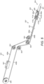
- FIG 4 illustrates a schematic drawing of the distal end of an exemplary robotic surgical instrument.
- the surgical instrument as a whole has the general form shown in figure 2 .
- the surgical instrument comprises a base 201 by which the surgical instrument connects to the surgical robot arm.
- the instrument base is designed cooperatively with the terminal end of the surgical robot arm, such that the instrument base is releasably attachable to the terminal end of the robot arm.
- a shaft 202 extends between the base 201 and an articulation 203.
- the articulation 203 is connected at its proximal end to the shaft 202 and at its distal end to an attachment suitable for attaching an end effector 204.
- the shaft 202 and articulation 203 are all hollow. This allows passage of driving elements up these sections to actuate the end effector 204. It also reduces the weight of the surgical instrument.
- the body of the articulation 203 is omitted from figure 4 for ease of illustration.
- the instrument has a diameter less than 8mm.
- the instrument has a 5mm diameter.
- the instrument may have a diameter which is less than 5mm.
- the instrument diameter may be the diameter of the shaft.
- the instrument diameter may be the diameter of the profile of the articulation.
- the diameter of the profile of the articulation matches or is narrower than the diameter of the shaft.
- the end effector of figure 4 has two opposing end effector elements 401 and 402, which are capable of cooperating so as to manipulate an object between them.
- the end effector may be of any suitable form able to function in this way.
- the end effector may be any one of: smooth jaws, serrated jaws, a gripper, a pair of tweezers, a pair of shears, a pair of blades, a stapler, a clamp, a cauteriser.
- the end effector elements illustrated in figure 4 are opposing first 401 and second 402 jaws.
- the articulation 203 comprises several joints which permit the end effector 204 to take a range of attitudes relative to the shaft 202 of the instrument.
- a first joint 403 (not fully shown) permits the end effector 204 as a whole to rotate about a first axis 404. This rotation is driven by driving elements (not shown). For example, the rotation may be cable driven.
- the first axis 404 is transverse to the longitudinal axis of the shaft 405.
- a second joint 406 permits the first end effector element 401 to rotate about a second axis 407.
- the second axis 407 is transverse to the first axis 404.
- a first pair of driving elements 409a, 409b drives rotation of the first end effector element 401 about the second axis 407.
- the first pair of driving elements comprises a first driving element 409a and a second driving element 409b.
- Tension applied to the first driving element 409a causes the first end effector element 401 to rotate towards the second end effector element 402.
- Tension applied to the second driving element 409b causes the first end effector element 401 to rotate away from the second end effector element 402.
- a third joint 408 permits the second end effector element 402 to rotate about the second axis 407.
- a second pair of driving elements 410a, 410b drives rotation of the second end effector element 402 about the second axis 407.
- the second pair of driving elements comprises a first driving element 410a and a second driving element 410b.
- Tension applied to the first driving element 410a causes the second end effector element 402 to rotate towards the first end effector element 401.
- Tension applied to the second driving element 410b causes the second end effector element 402 to rotate away from the first end effector element 401.
- each joint is driven by its own pair of driving elements. In other words, each joint is driven by a dedicated pair of driving elements.
- the joints are independently driven.
- the first end effector element 401 and the second end effector element 402 are independently rotatable about the second axis 407 by the second and third joints.
- the end effector elements may be rotated in the same direction or opposing directions by the second and third joints.
- the first end effector element 401 may be rotated about the second axis, whilst the second end effector element 402 is not rotated about the second axis.
- the second end effector element 402 may be rotated about the second axis, whilst the first end effector element 401 not rotated about the second axis.
- Figure 4 depicts the second joint 406 and the third joint 408 as permitting rotation about the same axis 407.
- the second and third joints may alternatively permit rotation of the end effector elements about different axes.
- the axis of rotation of one of the end effector elements may be offset in the longitudinal direction of the shaft 202 from the axis of rotation of the other end effector element.
- the axis of rotation of one of the end effector elements may be offset in a direction transverse to the longitudinal direction of the shaft 202 from the axis of rotation of the other end effector element.
- the axis of rotation of one of the end effector elements may not be parallel to the axis of rotation of the other end effector element.
- the axes of rotation of the end effector elements 401, 402 may be offset in the longitudinal direction of the shaft and/or offset in a direction perpendicular to the longitudinal direction of the shaft and/or angled with respect to each other. This may be desirable as a result of the end effector elements being asymmetric.
- a first end effector element may be powered and a second end effector element not powered and insulated from the first end effector element.
- the axes of rotation of the two end effector elements may be offset in the direction perpendicular to the longitudinal direction of the shaft.
- a first end effector element may be a blade and a second end effector element a flat cutting surface. To aid use of the blade, the axes of rotation of the two end effector elements may be angled to one another.
- the surgical instrument of figure 4 further comprises a pulley arrangement around which the first and second pairs of driving elements 409a,b and 410a,b are constrained to move.
- the pulley arrangement comprises three sets of pulleys.
- a first set of pulleys 411 is rotatable about the first axis 404.
- the first set of pulleys 411 rotate about the same axis as the first joint 403.
- the first set of pulleys 411 comprises a pair of pulleys 411a and 411b located on either side of the first joint 403.
- the first and second pairs of driving elements are constrained to extend over the first joint 403 in order to reach the second and third joints 406, 408 respectively.
- the first one of the first pair of driving elements 409a passes over one side of pulley 411a and the second one of the first pair of driving elements 409b passes over the opposing side of pulley 411b so that whatever rotation there is of the end effector about first axis 404, the length of each one of the first pair of driving elements 409a, 409b is maintained the same.
- the first one of the second pair of driving elements 410a passes over one side of pulley 411b and the second one of the second pair of driving elements 410b passes over the opposing side of pulley 411a so that whatever rotation there is of the end effector about first axis 404, the length of each one of the second pair of driving elements 410a, 410b is maintained the same.
- the pulley arrangement further comprises a second set of pulleys 412.
- the first set of pulleys 411 are located between the second set of pulleys 412 and the end effector 204.
- the second set of pulleys 412 comprise a pair of pulleys 412a and 412b located on either side of the first joint 403.
- the first pulley 412a is rotatable about a third axis 414 which is parallel to the first axis 404.
- the third axis 414 may be offset from the first axis 404 both in the longitudinal direction of the shaft and also transverse to the longitudinal direction of the shaft.
- the second pulley 412b is rotatable about a fourth axis 415 which is parallel to the first axis 404.
- the fourth axis 415 is offset from the first axis 404 both in the longitudinal direction of the shaft and also transverse to the longitudinal direction of the shaft.
- the third and fourth axes are parallel but offset from each other.
- the third axis 414 and fourth axis 415 are in the same plane perpendicular to the longitudinal direction of the shaft.
- the pulley arrangement further comprises a pair of redirecting pulleys 413a and 413b.
- the redirecting pulleys 413a and 413b are located between the first set of pulleys 411 and the end effector 204.
- the redirecting pulleys are positioned so as to redirect the driving elements 409a, 409b from the first set of pulleys 411 to the second joint 406, and to redirect the driving elements 410a, 410b from the first set of pulleys 411 to the third joint 408.
- the redirecting pulleys ensure that the first and second pairs of driving elements maintain the same contact with the second and third joints whatever rotation there is of the end effector about the first axis 404.
- first and second pairs of driving elements maintain the same amount of wrap around the second and third joints whatever the configuration of the instrument. This in turn ensures that the rotational range able to be imparted to the second and third joints by the first and second pairs of driving elements is maintained the same regardless of the pose position of the end effector.
- the pulley arrangement ensures that in every configuration of the surgical instrument, the first and second pairs of driving elements remain taut, do not snag on the articulation or each other, and maintain sufficient wrap around the second and third joints. By avoiding slack in the driving elements, there is no backlash when articulating the joints of the surgical instrument. Thus, full control of the movement of the surgical instrument is achieved in every configuration of the surgical instrument.
- Alternative pulley arrangements to those illustrated in figure 4 may be utilised. Fewer or more pulleys may be used.
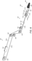
- Figure 5 illustrates the path of the first pair of driving elements 409a, 409b in the surgical instrument. Only the first pair of driving elements and the components that the first pair of driving elements come into contact with are illustrated. The distal end of the instrument comprising articulation 203 and end effector element 401 is as described with respect to figure 4 . The extent of the driving elements down the shaft 202 is not fully depicted, but abbreviated as indicated at 501. The remainder of the instrument structure that the first pair of driving elements contacts is in the instrument interface at the proximal end of the instrument 201.
- the instrument interface comprises a drive mechanism for transferring drive from the robot arm to the driving elements.
- the drive mechanism comprises a plurality of actuators. Each actuator is secured to a pair of driving elements. In figure 5 , first actuator 507 is secured to the first pair of driving elements 409a, 409b. Each actuator is secured to an instrument interface element (not shown on figure 5 ). Each instrument interface engages a corresponding drive assembly interface element of the robot arm. Each actuator is linearly displaceable.
- the robot arm transfers drive to the end effector element as follows: movement of a drive assembly interface element moves an instrument interface element which moves an actuator which moves a driving element which moves a joint of the articulation which moves the end effector element.
- the first one of the first pair of driving elements 409a is constrained to move around pulleys 502 and 503 in the instrument interface.
- the second one of the first pair of driving elements 409b is constrained to move around pulleys 504, 505 and 506 in the instrument interface. These pulleys act to direct the first pair of driving elements from the shaft 202 to the first actuator 507.
- Figure 6 illustrates the path of the second pair of driving elements 410a, 410b in the surgical instrument. Only the second pair of driving elements and the components that the second pair of driving elements come into contact with are illustrated.
- the distal end of the instrument comprising articulation 203 and end effector element 402 is as described with respect to figure 4 .
- the extent of the driving elements down the shaft 202 is not fully depicted, but abbreviated as indicated at 501.
- the remainder of the instrument structure that the second pair of driving elements contacts is in the instrument interface at the proximal end of the instrument 201.
- Second actuator 607 of the drive mechanism in the proximal end of the instrument 201 is secured to the second pair of driving elements 410a, 410b.
- the first one of the second pair of driving elements 410a is constrained to move around pulleys 602 and 603 in the instrument interface.
- the second one of the second pair of driving elements 410b is constrained to move around pulleys 604, 605 and 606 in the instrument interface. These pulleys act to direct the second pair of driving elements from the shaft 202 to the second actuator 607.
- Figures 7 and 8 illustrate the paths of pairs of driving elements 710a, 710b and 809a, 809b which are used to drive the motion of a stapler end effector.
- the stapler end effector comprises a first end effector part 701 and a second end effector part 802.
- the first end effector part 701 comprises a stapler block 716 which houses a bank of staples 714.
- the first end effector part 701 also comprises a stapler applicator 715.
- Driving elements 710a and 710b pass from the articulation into the stapler block 716 and terminate at either end of the stapler applicator 715.
- the driving elements 710a and 710b are rigidly attached to the stapler applicator 715.
- the driving elements wrap around pulley 713 at the distal end of the stapler block 716.
- the stapler applicator 715 is linearly displaceable within the stapler block 716.
- the stapler applicator 715 may be permitted to slide within a channel or along a rail in the stapler block 716.
- the stapler applicator 715 is linearly displaceable relative to the articulation.
- the stapler applicator 715 is moveable in the direction marked by the arrow A, and in the opposing direction to A.
- the stapler applicator 715 engages the staples 714 as it moves. This causes the staples 714 to become exposed outside the stapler block 716.
- the staples are caused to close as a result of the stapler block being pressed against another item.
- the second end effector part 802 comprises a stapler block 814 which houses a stapler blade 815.
- Driving elements 809a and 809b pass from the articulation into the stapler block 814 and terminate at either end of the stapler blade 815.
- the driving elements 809a and 809b are rigidly attached to the stapler blade 815.
- the driving elements wrap around pulley 816 at the distal end of the stapler block 814.
- the stapler blade 815 is linearly displaceable within the stapler block 814.
- the stapler blade 815 may be permitted to slide within a channel or along a rail in the stapler block 814.
- the stapler blade 815 is linearly displaceable relative to the articulation.
- the stapler blade 815 is moveable in the direction marked by the arrow A, and in the opposing direction to A.
- the stapler blade 815 is exposed outside the stapler block 814.
- tissue is clamped between the stapler block 814 and the stapler block 716.
- the stapler applicator 715 is drawn from the distal end of the stapler end effector part 701 to the proximal end of the stapler end effector part 701 by tensioning driving element 710a.
- the stapler applicator 715 engages the staples 714 causing them to be exposed outside the stapler block 716 and into the tissue clamped between the end effector parts.
- the staples penetrate through the tissue and are closed as they press against the other stapler block 814.
- the stapler blade 815 is drawn from the distal end of the stapler end effector part 802 to the proximal end of the stapler end effector part 802 by tensioning driving element 809a. This causes the stapler blade 815 to cut through the tissue clamped between the two end effector parts.
- each driving element is shown as wrapping around two pulleys in the articulation.
- For driving element 809b these are pulleys 812 and 813.
- For driving element 710a these are pulleys 711 and 712.
- For driving element 710b these are pulleys 708 and 709.
- These pulleys enable the end effector to rotate relative to the shaft of the instrument, as described with reference to pulleys 411a, 411b, 412a and 412b of figures 4 to 6 . Further pulleys may be used to enable further degrees of freedom of movement of the stapler end effector relative to the instrument shaft.
- One, or both, of the end effector parts 701 and 802 may be rotatable relative to the other end effector part. This may be implemented by incorporating a joint equivalent to joint 406 on one or each end effector part, and a further pair of driving elements to wrap around that joint, so as to permit rotation of the end effector part relative to the articulation about the joint. This thereby enables the end effector parts to open and close relative to each other, to thereby clamp material between them.
- figures 7 and 8 only illustrate those components of the instrument which the driving elements come into contact with.
- the extent of the driving elements down the shaft has been abbreviated, as indicated at 501.
- the internal structure of the instrument of figures 7 and 8 at the proximal end of the instrument is as described with reference to figures 5 and 6 .
- the drive mechanism, and its connection to the drive assembly interface of the robot arm, operates as described with reference to figures 5 and 6 .
- the stapling and cutting actions are implemented by drawing the stapler applicator 715 and stapler blade 815 from the distal end of the end effector to the proximal end of the end effector in the direction labelled A on figures 7 and 8 .
- the stapling and cutting actions are implementing by drawing the stapler applicator 715 and stapler blade 815 from the proximal end of the end effector to the distal end of the end effector in the opposite direction to that labelled A on figures 7 and 8 .
- one of the stapler applicator 715 and stapler blade 815 may be actioned by drawing it from the distal end to the proximal end of the end effector, and the other one of the stapler applicator 715 and stapler blade 815 actioned by drawing it from the proximal end to the distal end of the end effector.
- the driving elements of figures 4 to 8 are elongate elements which extend from the joints in the articulation 203 through the shaft to the instrument interface 201.
- each driving element can be flexed laterally to its main extent at least in those regions where it engages the internal components of the articulation and instrument interface.
- each driving element can be flexed transverse to its longitudinal axis in the specified regions. This flexibility enables the driving elements to wrap around the internal structure of the instrument, such as the joints and pulleys.
- the driving elements may be wholly flexible transverse to their longitudinal axes.
- the driving elements are not flexible along their main extents.
- the driving elements resist compression and tension forces applied along their length. In other words, the driving elements resist compression and tension forces acting in the direction of their longitudinal axes.
- the driving elements are able to transfer drive from the instrument interface to the joints of the articulation.
- the driving elements may be cables.
- Each pair of driving elements may be a uniform component having the same shape and size along its length and constructed of the same material along its length.
- each pair of driving elements may be composed of different portions.
- the portion of a driving element which engages components of the instrument interface (such as pulleys and interface elements) is flexible.
- the portion of the driving element which engages components of the distal end of the surgical instrument (such as the pulleys and joints in the articulation) is flexible.
- it may be a cable.
- spokes Between these two flexible portions are spokes.
- each pair of driving elements comprises two spokes and two flexible portions.
- Each pair of driving elements forms a loop. The loop comprises alternating spokes and flexible portions.
- the two spokes are predominantly or wholly enclosed in the instrument shaft.
- a distal flexible portion terminates at one end in the distal end of one of the spokes, and at the other end in the distal end of the other spoke.
- the distal flexible portion engages components of the articulation.
- a proximal flexible portion terminates at one end in the proximal end of one of the spokes, and at the other end in the proximal end of the other spoke.
- the proximal flexible portion engages components of the instrument interface.
- the spokes are stiffer than the flexible portions.
- the spokes are rigid.
- the spokes may be hollow tubes. Typically, the spokes have a larger diameter than the flexible portions.
- the flexible portions may terminate where they meet the spokes.
- the spokes may encapsulate the material of the flexible portions.
- the spokes may be rigid sheaths which cover flexible cables.
- the first pair of driving elements 409a, 409b is secured to the second joint 406.
- the first pair of driving elements is secured to the second joint with a ball and crimp termination.
- the first pair of driving elements is also secured to the first actuator 507.
- the first pair of driving elements may be integrally formed. For example, they may be a continuous cable. Alternatively, the first pair of driving elements may be disconnected where they are secured to the second joint and/or where they are secured to the first actuator.
- the second pair of driving elements 410a, 410b is secured to the third joint 408.
- the second pair of driving elements may be secured to the second joint with a ball and crimp termination.
- the second pair of driving elements is also secured to the second actuator 607.
- the second pair of driving elements may be integrally formed.
- they may be a continuous cable.
- the second pair of driving elements may be disconnected where they are secured to the third joint and/or where they are secured to the second actuator.
- driving elements 809a and 809b are secured to the first actuator 507, and also secured to the stapler blade 815.
- This pair of driving elements may be integrally formed. For example, they may be a continuous cable. Alternatively, this pair of driving elements may be disconnected where they are secured to the stapler blade 815 and/or where they are secured to the first actuator 507.
- the driving elements resist tension forces acting along their length.
- an actuator when driven by the drive assembly, it applies a tension force to the driving element.
- this causes a rotational force to be applied to the joint it terminates at in the articulation.
- This causes the end effector element to rotate with the rotational force.
- this causes a linear force to be applied to the end effector element (stapler blade 815/stapler applicator 715).
- the rotational/linear force of the end effector element is not as large as the tension force applied to the driving element in the instrument interface due to a loss in tension of the driving element. This loss in tension force is primarily caused by friction between the driving element and the pulleys that it is constrained to move around between the actuator and the joint it is driving.
- each of the driving elements of a pair of driving elements between the actuator and the joint they are driving are asymmetric.
- the maximum motion force which is imparted to the end effector element is different for the two motion directions of the end effector element.
- the priority rotational direction for each end effector element may be that which effects the opening of the end effector elements away from each other.
- an end effector which is a clamp may comprise two clamping end effector elements which hold apart two sections of tissue to maintain an opening. Another instrument may then manipulate the site inside the opening maintained by the clamp. In this case, the priority rotational direction for each clamping end effector element is away from the other clamping end effector element.
- an end effector may apply a clip or ligature into the surgical site. The clip or ligature is biased closed. The end effector applies force to open or hold open the clip or ligature to position it in the surgical site. In this case, the priority rotational direction for each end effector element is away from the other end effector element.
- the end effector is a stapler.
- the two end effector parts are used to staple tissue clamped between them and then sever that tissue using the blade.
- the priority linear direction for each end effector part is that which effects the stapling action and the blade action.
- the priority linear direction for both the stapler blade 815 and the stapler applicator 715 in the arrangement depicted in figures 7 and 8 is towards the articulation from the distal end of the end effector in the direction A.
- the force with which the stapler blade and the stapler applicator reset to their original positions is not as important. If the blade and stapler were to operate so as to cut and staple in the opposite direction to that shown in figures 7 and 8 , then the priority linear direction would be the direction opposite to A.
- the position of the end effector relative to the terminal link of the robot arm may be determined by measuring the displacement of the actuators 507, 607 or by measuring the displacement of the instrument interface elements secured to the actuators, or by measuring the displacement of the drive assembly interface elements engaged with the instrument interface elements.
- Each displacement is measured using a position sensor which has a fixed position relative to the terminal link of the robot arm.
- Each sensed position can be used in combination with the other sensed positions, the known configuration of the internal structure of the instrument (pulleys etc) about which the driving elements are constrained to move, the lengths of the driving elements, and the shape and size of the end effector elements, to determine the position of the end effector relative to the terminal link of the robot arm.
- the paths of each of the driving elements of a pair of driving elements between the actuator and the element they are driving are asymmetric.
- the determination of the end effector position using the above mechanism assumes that the lengths of the driving elements remain static. Any change to the length of the driving element caused by its interaction with the internal structure of the instrument (pulleys etc) or as a result of it stretching, will reduce the accuracy of the determined end effector element position. The longer the driving element, the more inaccurate the end effector element position determined in this manner. The more internal structure over which the driving element is constrained to move, the more inaccurate the end effector element position determined in this manner.
- the priority motion direction may be chosen to be the direction which it is most important has the most accurate sensed position of the end effector element.
- the path of the driving element which is tensioned to effect motion of the end effector element in the priority motion direction has a lower tension force loss than the path of the driving element which is tensioned to effect motion of the end effector element in the opposing non-priority motion direction.
- any one or combination of these approaches may be used to configure an asymmetric driving mechanism for the instrument such that for a given number of joints, driving elements, and pulleys, the force transferred to the end effector for implementing the priority actuation (be it closing or opening, linear displacement in one direction or the other) is maximised at the cost of reducing the force transferred to the end effector for implementing the non-priority actuation.
- the instrument could be used for non-surgical purposes. For example it could be used in a cosmetic procedure.
Landscapes
- Health & Medical Sciences (AREA)
- Surgery (AREA)
- Life Sciences & Earth Sciences (AREA)
- Engineering & Computer Science (AREA)
- Medical Informatics (AREA)
- General Health & Medical Sciences (AREA)
- Biomedical Technology (AREA)
- Heart & Thoracic Surgery (AREA)
- Nuclear Medicine, Radiotherapy & Molecular Imaging (AREA)
- Molecular Biology (AREA)
- Animal Behavior & Ethology (AREA)
- Veterinary Medicine (AREA)
- Public Health (AREA)
- Robotics (AREA)
- Reproductive Health (AREA)
- Vascular Medicine (AREA)
- Ophthalmology & Optometry (AREA)
- Surgical Instruments (AREA)
- Manipulator (AREA)
Claims (15)
- Chirurgisches Roboterinstrument (200), umfassend:einen Schaft (202);ein erstes Endeffektorelement (401);ein Gelenk (203), das das erste Endeffektorelement mit einem distalen Endedes Schafts verbindet, wobei das erste Endeffektorelement relativ zu dem Gelenk bewegbar ist; undeinen Antriebsmechanismus an einem proximalen Ende des Schafts, umfassend einen ersten Aktuator (507), wobei der erste Aktuator mit dem ersten Endeffektorelement durch ein erstes Paar von Antriebselementen (409a, 409b) verbunden ist, wobei das erste Paar von Antriebselementen so konfiguriert ist, dass eine Spannkraft, die durch den ersten Aktuator auf ein erstes von dem
ersten Paar von Antriebselementen ausgeübt wird, bewirkt, dass sich das erste Endeffektorelement relativ zu dem Gelenk in einer ersten Bewegungsrichtung bewegt, und die Spannkraft, die auf ein zweites von dem ersten Paar von Antriebselementen ausgeübt wird, bewirkt, dass sich das erste Endeffektorelement relativ zu dem Gelenk in einer zweiten Bewegungsrichtung bewegt;wobei das erste von dem ersten Paar von Antriebselementen einen ersten Pfad zwischen dem ersten Aktuator und dem ersten Endeffektorelement und das zweite von dem ersten Paar von Antriebselementen einen zweiten Pfad zwischen dem ersten Aktuator und dem ersten Endeffektorelement aufweist;wobei der erste Pfad einen geringeren Spannkraftverlust als der zweite Pfad aufweist, sodass die erste Bewegungsrichtung einen größeren Anteil der Spannkraft auf das erste Endeffektorelement überträgt als die zweite Bewegungsrichtung;wobei das chirurgische Roboterinstrument dadurch gekennzeichnet ist, dass das erste von dem ersten Paar von Antriebselementen aus einer geringeren Anzahl von dickeren Strängen aufgebaut ist als das zweite von dem ersten Paar von Antriebselementen. - Chirurgisches Roboterinstrument nach Anspruch 1, wobei das erste des ersten Paars von Antriebselementen einen größeren Durchmesser als das zweite des ersten Paars von Antriebselementen aufweist.
- Chirurgisches Roboterinstrument nach Anspruch 1 oder 2, ferner umfassend:ein zweites Endeffektorelement (402);das Gelenk, das das zweite Endeffektorelement mit dem distalen Ende des Schafts verbindet, wobei das zweite Endeffektorelement relativ zu dem Gelenk bewegbar ist; undden Antriebsmechanismus, umfassend einen zweiten Aktuator (607), wobei der zweite Aktuator mit dem zweiten Endeffektorelement durch ein zweites Paar von Antriebselementen (410a, 410b) verbunden ist, wobei das zweite Paar von Antriebselementen so konfiguriert ist, dass eine von dem zweiten Aktuator auf ein erstes von dem zweiten Paar von Antriebselementen ausgeübte Spannkraft bewirkt, dass sich das zweite Endeffektorelement relativ zu dem Gelenk in der zweiten Bewegungsrichtung bewegt, und die auf ein zweites von dem zweiten Paar von Antriebselementen ausgeübte Spannkraft bewirkt, dass sich das zweite Endeffektorelement relativ zu dem Gelenk in der ersten Bewegungsrichtung bewegt;wobei das erste von dem zweiten Paar von Antriebselementen einen dritten Pfad zwischen dem zweiten Aktuator und dem zweiten Endeffektorelement aufweist, und das zweite von dem zweiten Paar von Antriebselementen einen vierten Pfad zwischen dem zweiten Aktuator und dem zweiten Endeffektorelement aufweist, wobei der dritte Pfad einen geringeren Spannkraftverlust als der vierte Pfad aufweist, sodass die zweite Bewegungsrichtung einen größeren Anteil der Spannkraft auf das zweite Endeffektorelement überträgt als die erste Bewegungsrichtung.
- Chirurgisches Roboterinstrument nach Anspruch 3, wobei das erste von dem zweiten Paar von Antriebselementen aus einer geringeren Anzahl von dickeren Strängen aufgebaut ist als das zweite von dem zweiten Paar von Antriebselementen.
- Chirurgisches Roboterinstrument nach Anspruch 3 oder 4, wobei das erste von dem zweiten Paar von Antriebselementen einen größeren Durchmesser als das zweite von dem zweiten Paar von Antriebselementen aufweist.
- Chirurgisches Roboterinstrument nach einem der Ansprüche 3 bis 5, wobei eine Kontaktlänge des ersten Pfads, der die innere Struktur des chirurgischen Roboterinstruments berührt, kleiner ist als eine Kontaktlänge des zweiten Pfads, der die innere Struktur des chirurgischen Roboterinstruments berührt, und eine Kontaktlänge des dritten Pfads, die die innere Struktur des chirurgischen Roboterinstruments berührt, kleiner ist als eine Kontaktlänge des vierten Pfads, der die innere Struktur des chirurgischen Roboterinstruments berührt.
- Chirurgisches Roboterinstrument nach einem der Ansprüche 3 bis 5, wobei eine Gesamtlänge des ersten Pfads kleiner ist als eine Gesamtlänge des zweiten Pfads, und eine Gesamtlänge des dritten Pfads kleiner ist als eine Gesamtlänge des vierten Pfads.
- Chirurgisches Roboterinstrument nach einem der Ansprüche 3 bis 7, wobei der erste Pfad mit dem dritten Pfad übereinstimmt und der zweite Pfad mit dem vierten Pfad übereinstimmt.
- Chirurgisches Roboterinstrument nach einem der Ansprüche 3 bis 8, wobei das erste von dem ersten Paar von Antriebselementen zum Bewegen um M Rollen beschränkt ist, und das zweite von dem ersten Paar von Antriebselementen zum Bewegen um N Rollen beschränkt ist, wobei M < N oder M < N-1, und das erste von dem zweiten Paar von Antriebselementen zum Bewegen um J Rollen beschränkt ist, und das zweite von dem zweiten Paar von Antriebselementen zum Bewegen um K Rollen beschränkt ist, wobei J < K oder J < K-1.
- Chirurgisches Roboterinstrument nach einem der Ansprüche 3 bis 9, wobei das erste Endeffektorelement relativ zu dem Gelenk um eine erste Achse drehbar ist, und das erste Paar von Antriebselementen so konfiguriert ist, dass die von dem ersten Aktuator auf das erste von dem ersten Paar von Antriebselementen ausgeübte Spannkraft bewirkt, dass sich das erste Endeffektorelement in einer ersten Drehrichtung um die erste Achse dreht, und die Spannkraft, die auf das zweite von dem ersten Paar von Antriebselementen ausgeübt wird, bewirkt, dass sich das erste Endeffektorelement in einer zweiten Drehrichtung um die erste Achse dreht, und das zweite Endeffektorelement relativ zu dem Gelenk um die erste Achse drehbar ist, und das zweite Paar von Antriebselementen so konfiguriert ist, dass eine von dem zweiten Aktuator auf das erste von dem zweiten Paar von Antriebselementen ausgeübte Spannkraft bewirkt, dass sich das zweite Endeffektorelement in der zweiten Drehrichtung um die erste Achse dreht, und die auf das zweite von dem zweiten Paar von Antriebselementen ausgeübte Spannkraft bewirkt, dass sich das zweite Endeffektorelement in der ersten Drehrichtung um die erste Achse dreht.
- Chirurgisches Roboterinstrument nach Anspruch 10, das so konfiguriert ist, dass eine von dem ersten Aktuator auf das erste von dem ersten Paar von Antriebselementen ausgeübte Spannkraft bewirkt, dass sich das erste Endeffektorelement hin zu dem zweiten Endeffektorelement dreht, und eine von dem zweiten Aktuator auf das erste von dem zweiten Paar von Antriebselementen ausgeübte Spannkraft bewirkt, dass sich das zweite Endeffektorelement hin zu dem ersten Endeffektorelement dreht.
- Chirurgisches Roboterinstrument nach Anspruch 10, das so konfiguriert ist, dass eine von dem ersten Aktuator auf das erste von dem ersten Paar von Antriebselementen ausgeübte Spannkraft bewirkt, dass sich das erste Endeffektorelement weg von dem zweiten Endeffektorelement dreht, und eine von dem zweiten Aktuator auf das erste von dem zweiten Paar von Antriebselementen ausgeübte Spannkraft bewirkt, dass sich das zweite Endeffektorelement weg von dem ersten Endeffektorelement dreht.
- Chirurgisches Roboterinstrument nach einem der Ansprüche 10 bis 12, wobei das erste und das zweite Endeffektorelement einer ersten und einer zweiten Backe eines Endeffektors gegenüberliegen.
- Chirurgisches Roboterinstrument nach einem der Ansprüche 3 bis 9, wobei das erste Endeffektorelement relativ zu dem Gelenk linear verschiebbar ist, und das erste Paar von Antriebselementen so konfiguriert ist, dass die von dem ersten Aktuator auf das erste von dem ersten Paar von Antriebselementen ausgeübte Spannkraft bewirkt, dass sich das erste Endeffektorelement in einer ersten linearen Richtung linear verschiebt, und die auf das zweite von dem ersten Paar von Antriebselementen ausgeübte Spannkraft bewirkt, dass sich das erste Endeffektorelement in einer zweiten linearen Richtung, die entgegengesetzt zu der ersten linearen Richtung ist, linear verschiebt, und wobei das zweite Endeffektorelement relativ zu dem Gelenk linear verschiebbar ist, und das zweite Paar von Antriebselementen so konfiguriert ist, dass die von dem zweiten Aktuator auf das erste von dem zweiten Paar von Antriebselementen ausgeübte Spannkraft bewirkt, dass sich das zweite Endeffektorelement in der ersten linearen Richtung linear verschiebt, und die auf das zweite von dem zweiten Paar von Antriebselementen ausgeübte Spannkraft bewirkt, dass sich das zweite Endeffektorelement in der zweiten linearen Richtung linear verschiebt.
- Chirurgisches Roboterinstrument nach Anspruch 14, wobei das erste Endeffektorelement Teil eines Klammergeräts ist.
Applications Claiming Priority (3)
| Application Number | Priority Date | Filing Date | Title |
|---|---|---|---|
| GB1617448.4A GB2554915B (en) | 2016-10-14 | 2016-10-14 | Driving arrangement for articulating a surgical instrument |
| PCT/GB2017/053038 WO2018069679A1 (en) | 2016-10-14 | 2017-10-06 | Driving arrangement for articulating a surgical instrument |
| EP17783982.6A EP3525710B1 (de) | 2016-10-14 | 2017-10-06 | Antriebsanordnung zur anwinkelung bei einem chirurgischen instrument |
Related Parent Applications (2)
| Application Number | Title | Priority Date | Filing Date |
|---|---|---|---|
| EP17783982.6A Division EP3525710B1 (de) | 2016-10-14 | 2017-10-06 | Antriebsanordnung zur anwinkelung bei einem chirurgischen instrument |
| EP17783982.6A Division-Into EP3525710B1 (de) | 2016-10-14 | 2017-10-06 | Antriebsanordnung zur anwinkelung bei einem chirurgischen instrument |
Publications (2)
| Publication Number | Publication Date |
|---|---|
| EP4032494A1 EP4032494A1 (de) | 2022-07-27 |
| EP4032494B1 true EP4032494B1 (de) | 2024-09-11 |
Family
ID=57680676
Family Applications (3)
| Application Number | Title | Priority Date | Filing Date |
|---|---|---|---|
| EP17783982.6A Active EP3525710B1 (de) | 2016-10-14 | 2017-10-06 | Antriebsanordnung zur anwinkelung bei einem chirurgischen instrument |
| EP22161573.5A Active EP4032495B1 (de) | 2016-10-14 | 2017-10-06 | Antriebsanordnung zur anwinkelung bei einem chirurgischen instrument |
| EP22161569.3A Active EP4032494B1 (de) | 2016-10-14 | 2017-10-06 | Antriebsanordnung zur anwinkelung bei einem chirurgischen instrument |
Family Applications Before (2)
| Application Number | Title | Priority Date | Filing Date |
|---|---|---|---|
| EP17783982.6A Active EP3525710B1 (de) | 2016-10-14 | 2017-10-06 | Antriebsanordnung zur anwinkelung bei einem chirurgischen instrument |
| EP22161573.5A Active EP4032495B1 (de) | 2016-10-14 | 2017-10-06 | Antriebsanordnung zur anwinkelung bei einem chirurgischen instrument |
Country Status (6)
| Country | Link |
|---|---|
| US (1) | US11129686B2 (de) |
| EP (3) | EP3525710B1 (de) |
| JP (1) | JP7018441B2 (de) |
| CN (1) | CN110121308B (de) |
| GB (1) | GB2554915B (de) |
| WO (1) | WO2018069679A1 (de) |
Families Citing this family (73)
| Publication number | Priority date | Publication date | Assignee | Title |
|---|---|---|---|---|
| US9232959B2 (en) | 2007-01-02 | 2016-01-12 | Aquabeam, Llc | Multi fluid tissue resection methods and devices |
| US12290277B2 (en) | 2007-01-02 | 2025-05-06 | Aquabeam, Llc | Tissue resection with pressure sensing |
| EP3622910B1 (de) | 2008-03-06 | 2024-07-10 | AquaBeam LLC | Gewebeablation und kauterisation mit in einem flüssigkeitsstrom getragener optischer energie |
| CN108606773B (zh) | 2012-02-29 | 2020-08-11 | 普罗赛普特生物机器人公司 | 自动化图像引导的组织切除和处理 |
| US10231867B2 (en) | 2013-01-18 | 2019-03-19 | Auris Health, Inc. | Method, apparatus and system for a water jet |
| US10744035B2 (en) | 2013-06-11 | 2020-08-18 | Auris Health, Inc. | Methods for robotic assisted cataract surgery |
| US10426661B2 (en) | 2013-08-13 | 2019-10-01 | Auris Health, Inc. | Method and apparatus for laser assisted cataract surgery |
| US10550918B2 (en) | 2013-08-15 | 2020-02-04 | Intuitive Surgical Operations, Inc. | Lever actuated gimbal plate |
| US10076348B2 (en) | 2013-08-15 | 2018-09-18 | Intuitive Surgical Operations, Inc. | Rotary input for lever actuation |
| US20160287279A1 (en) | 2015-04-01 | 2016-10-06 | Auris Surgical Robotics, Inc. | Microsurgical tool for robotic applications |
| US9955986B2 (en) | 2015-10-30 | 2018-05-01 | Auris Surgical Robotics, Inc. | Basket apparatus |
| US10231793B2 (en) | 2015-10-30 | 2019-03-19 | Auris Health, Inc. | Object removal through a percutaneous suction tube |
| US9949749B2 (en) | 2015-10-30 | 2018-04-24 | Auris Surgical Robotics, Inc. | Object capture with a basket |
| CN114587609B (zh) | 2016-07-14 | 2025-01-28 | 直观外科手术操作公司 | 多线缆医疗器械 |
| CN115349951A (zh) | 2016-11-21 | 2022-11-18 | 直观外科手术操作公司 | 线缆长度持恒的医疗器械 |
| US10357321B2 (en) | 2017-02-24 | 2019-07-23 | Intuitive Surgical Operations, Inc. | Splayed cable guide for a medical instrument |
| EP3599979A4 (de) | 2017-03-28 | 2021-01-06 | Auris Health, Inc. | Schaftbetätigungsgriff |
| KR102550962B1 (ko) | 2017-04-07 | 2023-07-06 | 아우리스 헬스, 인코포레이티드 | 환자 삽입기(Introducer) 정렬 |
| US10285574B2 (en) | 2017-04-07 | 2019-05-14 | Auris Health, Inc. | Superelastic medical instrument |
| KR102332121B1 (ko) | 2017-12-14 | 2021-12-01 | 인튜어티브 서지컬 오퍼레이션즈 인코포레이티드 | 인장 밴드를 갖는 의료 도구 |
| CN119837643A (zh) | 2018-03-07 | 2025-04-18 | 直观外科手术操作公司 | 具有易组装构件的低摩擦小型医疗工具 |
| EP3761897A4 (de) | 2018-03-07 | 2021-11-24 | Intuitive Surgical Operations, Inc. | Reibungsarme medizinische werkzeuge mit kleinem profil und montagefreundlichen bauteilen |
| EP3761895A4 (de) | 2018-03-07 | 2021-11-24 | Intuitive Surgical Operations, Inc. | Reibungsarme medizinische werkzeuge mit walzenunterstützten spannelementen |
| EP3773302B1 (de) | 2018-04-10 | 2025-06-04 | Intuitive Surgical Operations, Inc. | Gelenkige medizinprodukte mit flexibler drahtführung |
| CN112218596B (zh) | 2018-06-07 | 2025-05-16 | 奥瑞斯健康公司 | 具有高力器械的机器人医疗系统 |
| WO2020005854A1 (en) | 2018-06-28 | 2020-01-02 | Auris Health, Inc. | Medical systems incorporating pulley sharing |
| US11259798B2 (en) | 2018-07-16 | 2022-03-01 | Intuitive Surgical Operations, Inc. | Medical devices having tissue grasping surfaces and features for manipulating surgical needles |
| US11612447B2 (en) | 2018-07-19 | 2023-03-28 | Intuitive Surgical Operations, Inc. | Medical devices having three tool members |
| CN112566584A (zh) | 2018-08-15 | 2021-03-26 | 奥瑞斯健康公司 | 用于组织烧灼的医疗器械 |
| EP3806758A4 (de) | 2018-08-17 | 2022-04-06 | Auris Health, Inc. | Bipolares medizinisches instrument |
| WO2020068303A1 (en) | 2018-09-26 | 2020-04-02 | Auris Health, Inc. | Systems and instruments for suction and irrigation |
| US11576738B2 (en) | 2018-10-08 | 2023-02-14 | Auris Health, Inc. | Systems and instruments for tissue sealing |
| CN120036942A (zh) | 2018-11-15 | 2025-05-27 | 直观外科手术操作公司 | 将工具轴与缆绳驱动负载解除联接 |
| US12048504B2 (en) | 2018-11-15 | 2024-07-30 | Intuitive Surgical Operations, Inc. | Cable drive limited slip capstan and shaft |
| US11291514B2 (en) | 2018-11-15 | 2022-04-05 | Intuitive Surgical Operations, Inc. | Medical devices having multiple blades and methods of use |
| CN109498096A (zh) * | 2018-12-15 | 2019-03-22 | 苏州康多机器人有限公司 | 一种多自由度增大夹持力的结扎钳 |
| EP3870075B1 (de) | 2018-12-20 | 2025-06-11 | Auris Health, Inc. | Abschirmung für handgelenkinstrumente |
| EP3883492B1 (de) | 2019-01-25 | 2025-05-21 | Auris Health, Inc. | Gefässversiegelungsvorrichtung mit heizmöglichkeiten |
| WO2020197625A1 (en) | 2019-03-25 | 2020-10-01 | Auris Health, Inc. | Systems and methods for medical stapling |
| CN110123420B (zh) * | 2019-06-01 | 2020-12-08 | 青岛大学附属医院 | 一种消化内镜微创手术刀装置 |
| CN121041038A (zh) | 2019-06-13 | 2025-12-02 | 直观外科手术操作公司 | 用于致动张力带的带有长度守恒机构的医疗工具 |
| EP3989862A4 (de) | 2019-06-25 | 2023-10-04 | Auris Health, Inc. | Medizinische instrumente mit handgelenken mit hybriden umleitungsoberflächen |
| US11369386B2 (en) | 2019-06-27 | 2022-06-28 | Auris Health, Inc. | Systems and methods for a medical clip applier |
| EP3989863A4 (de) | 2019-06-28 | 2023-10-11 | Auris Health, Inc. | Medizinische instrumente mit handgelenken mit hybriden umleitungsoberflächen |
| US11896330B2 (en) | 2019-08-15 | 2024-02-13 | Auris Health, Inc. | Robotic medical system having multiple medical instruments |
| WO2021059099A1 (en) | 2019-09-26 | 2021-04-01 | Auris Health, Inc. | Systems and methods for collision detection and avoidance |
| US12324645B2 (en) | 2019-09-26 | 2025-06-10 | Auris Health, Inc. | Systems and methods for collision avoidance using object models |
| US11737845B2 (en) | 2019-09-30 | 2023-08-29 | Auris Inc. | Medical instrument with a capstan |
| US11737835B2 (en) | 2019-10-29 | 2023-08-29 | Auris Health, Inc. | Braid-reinforced insulation sheath |
| CN114727850A (zh) | 2019-11-21 | 2022-07-08 | 奥瑞斯健康公司 | 用于覆盖外科系统的系统和方法 |
| JP7640052B2 (ja) | 2019-12-31 | 2025-03-05 | オーリス ヘルス インコーポレイテッド | 高度バスケット駆動モード |
| WO2021137104A1 (en) | 2019-12-31 | 2021-07-08 | Auris Health, Inc. | Dynamic pulley system |
| WO2021198801A1 (en) | 2020-03-30 | 2021-10-07 | Auris Health, Inc. | Workspace optimization for robotic surgery |
| WO2022003485A1 (en) | 2020-06-29 | 2022-01-06 | Auris Health, Inc. | Systems and methods for detecting contact between a link and an external object |
| US11357586B2 (en) | 2020-06-30 | 2022-06-14 | Auris Health, Inc. | Systems and methods for saturated robotic movement |
| US11931901B2 (en) | 2020-06-30 | 2024-03-19 | Auris Health, Inc. | Robotic medical system with collision proximity indicators |
| US12458533B2 (en) | 2020-08-13 | 2025-11-04 | Forsight Robotics Ltd. | Capsulorhexis apparatus and method |
| JP6991637B1 (ja) * | 2020-09-01 | 2022-01-13 | リバーフィールド株式会社 | 術具 |
| CN112741695B (zh) * | 2020-12-19 | 2025-07-15 | 深圳市精锋医疗科技股份有限公司 | 手术器械、从操作设备及手术机器人 |
| CN112807089B (zh) * | 2021-02-10 | 2022-05-03 | 诺创智能医疗科技(杭州)有限公司 | 手术器械和手术机器人 |
| KR20240037380A (ko) * | 2021-02-20 | 2024-03-21 | 주식회사 리브스메드 | 수술용 인스트루먼트의 엔드 툴 및 이를 구비한 전기 소작 수술용 인스트루먼트 |
| US12349903B2 (en) * | 2021-04-23 | 2025-07-08 | Livsmed Inc. | End tool of surgical instrument, and surgical instrument comprising same |
| KR102693538B1 (ko) * | 2021-04-23 | 2024-08-09 | 주식회사 리브스메드 | 수술용 인스트루먼트의 엔드 툴 |
| EP4349290A4 (de) * | 2021-05-29 | 2024-09-25 | Livsmed Inc. | Endwerkzeug für chirurgisches instrument und chirurgisches instrument zur elektrischen kauterisation damit |
| CA3218370A1 (en) | 2021-06-01 | 2022-12-08 | Forsight Robotics Ltd. | Kinematic structures and sterile drapes for robotic microsurgical procedures |
| JP7017286B1 (ja) * | 2021-06-30 | 2022-02-08 | リバーフィールド株式会社 | 手術器具 |
| EP4371503A4 (de) * | 2021-07-16 | 2024-11-06 | Livsmed Inc. | Endwerkzeug eines chirurgischen instruments und chirurgisches instrument damit |
| KR20240151261A (ko) | 2021-07-16 | 2024-10-17 | 주식회사 리브스메드 | 수술용 인스트루먼트의 엔드 툴 및 이를 구비한 전기 소작 수술용 인스트루먼트 |
| JP7725115B2 (ja) * | 2022-05-23 | 2025-08-19 | リブスメド インコーポレーテッド | 手術用インストルメントのエンドツールおよびそれを備えた電気焼灼手術用インストルメント |
| US12390266B2 (en) * | 2022-05-23 | 2025-08-19 | Livsmed Inc. | End tool of surgical instrument and electrocauterization surgical instrument comprising same |
| GB2622802B (en) * | 2022-09-28 | 2025-01-29 | Cmr Surgical Ltd | Securing a driving element in an instrument interface of a robotic surgical instrument |
| EP4654915A1 (de) * | 2023-01-25 | 2025-12-03 | Auris Health, Inc. | Relaxationsspannungsüberwachung und zielansteuern von medizinischen instrumenten |
| CN119385690B (zh) * | 2024-10-28 | 2025-12-02 | 中南大学 | 一种带力矩检测的从执行器 |
Family Cites Families (30)
| Publication number | Priority date | Publication date | Assignee | Title |
|---|---|---|---|---|
| US5507773A (en) * | 1994-02-18 | 1996-04-16 | Ethicon Endo-Surgery | Cable-actuated jaw assembly for surgical instruments |
| US5807376A (en) * | 1994-06-24 | 1998-09-15 | United States Surgical Corporation | Apparatus and method for performing surgical tasks during laparoscopic procedures |
| US5792135A (en) * | 1996-05-20 | 1998-08-11 | Intuitive Surgical, Inc. | Articulated surgical instrument for performing minimally invasive surgery with enhanced dexterity and sensitivity |
| US6364888B1 (en) * | 1996-09-09 | 2002-04-02 | Intuitive Surgical, Inc. | Alignment of master and slave in a minimally invasive surgical apparatus |
| US9050119B2 (en) * | 2005-12-20 | 2015-06-09 | Intuitive Surgical Operations, Inc. | Cable tensioning in a robotic surgical system |
| US6197017B1 (en) * | 1998-02-24 | 2001-03-06 | Brock Rogers Surgical, Inc. | Articulated apparatus for telemanipulator system |
| US6554844B2 (en) * | 1998-02-24 | 2003-04-29 | Endovia Medical, Inc. | Surgical instrument |
| US6394998B1 (en) * | 1999-01-22 | 2002-05-28 | Intuitive Surgical, Inc. | Surgical tools for use in minimally invasive telesurgical applications |
| US6206903B1 (en) * | 1999-10-08 | 2001-03-27 | Intuitive Surgical, Inc. | Surgical tool with mechanical advantage |
| US6902560B1 (en) * | 2000-07-27 | 2005-06-07 | Intuitive Surgical, Inc. | Roll-pitch-roll surgical tool |
| US6840938B1 (en) * | 2000-12-29 | 2005-01-11 | Intuitive Surgical, Inc. | Bipolar cauterizing instrument |
| US7699835B2 (en) * | 2001-02-15 | 2010-04-20 | Hansen Medical, Inc. | Robotically controlled surgical instruments |
| US8398634B2 (en) * | 2002-04-18 | 2013-03-19 | Intuitive Surgical Operations, Inc. | Wristed robotic surgical tool for pluggable end-effectors |
| US6676684B1 (en) * | 2001-09-04 | 2004-01-13 | Intuitive Surgical, Inc. | Roll-pitch-roll-yaw surgical tool |
| US7331967B2 (en) * | 2002-09-09 | 2008-02-19 | Hansen Medical, Inc. | Surgical instrument coupling mechanism |
| US20070208375A1 (en) * | 2006-02-23 | 2007-09-06 | Kouji Nishizawa | Surgical device |
| US8597182B2 (en) * | 2006-04-28 | 2013-12-03 | Intuitive Surgical Operations, Inc. | Robotic endoscopic retractor for use in minimally invasive surgery |
| JP4829005B2 (ja) * | 2006-05-12 | 2011-11-30 | テルモ株式会社 | マニピュレータ |
| US7935130B2 (en) * | 2006-11-16 | 2011-05-03 | Intuitive Surgical Operations, Inc. | Two-piece end-effectors for robotic surgical tools |
| KR101056204B1 (ko) * | 2008-06-27 | 2011-08-11 | 정창욱 | 최소 침습 수술 도구 |
| US8821480B2 (en) * | 2008-07-16 | 2014-09-02 | Intuitive Surgical Operations, Inc. | Four-cable wrist with solid surface cable channels |
| US9259274B2 (en) | 2008-09-30 | 2016-02-16 | Intuitive Surgical Operations, Inc. | Passive preload and capstan drive for surgical instruments |
| EP3760154B1 (de) * | 2009-11-13 | 2025-07-02 | Intuitive Surgical Operations, Inc. | Chirurgisches instrument mit einem kompakten handgelenk |
| US8644988B2 (en) * | 2010-05-14 | 2014-02-04 | Intuitive Surgical Operations, Inc. | Drive force control in medical instrument providing position measurements |
| IT1401438B1 (it) * | 2010-08-04 | 2013-07-26 | Surgica Robotica S P A | Utensile chirurgico robotizzato. |
| DE102012212510B4 (de) * | 2012-07-17 | 2014-02-13 | Richard Wolf Gmbh | Endoskopisches Instrument |
| WO2014151952A1 (en) * | 2013-03-14 | 2014-09-25 | Sri International | Compact robotic wrist |
| JP6150672B2 (ja) | 2013-08-26 | 2017-06-21 | オリンパス株式会社 | 医療用マニピュレータ |
| EP3104792B1 (de) * | 2014-02-12 | 2022-06-15 | Covidien LP | Chirurgische endeffektoren und riemenscheibenanordnungen davon |
| CN104116547B (zh) * | 2014-07-25 | 2016-04-06 | 上海交通大学 | 用于微创手术机器人的低摩擦小惯量手术器械 |
-
2016
- 2016-10-14 GB GB1617448.4A patent/GB2554915B/en active Active
-
2017
- 2017-10-06 EP EP17783982.6A patent/EP3525710B1/de active Active
- 2017-10-06 CN CN201780070720.7A patent/CN110121308B/zh active Active
- 2017-10-06 JP JP2019519987A patent/JP7018441B2/ja active Active
- 2017-10-06 EP EP22161573.5A patent/EP4032495B1/de active Active
- 2017-10-06 EP EP22161569.3A patent/EP4032494B1/de active Active
- 2017-10-06 WO PCT/GB2017/053038 patent/WO2018069679A1/en not_active Ceased
- 2017-10-06 US US16/340,254 patent/US11129686B2/en active Active
Also Published As
| Publication number | Publication date |
|---|---|
| CN110121308A (zh) | 2019-08-13 |
| GB2554915A (en) | 2018-04-18 |
| JP7018441B2 (ja) | 2022-02-10 |
| EP4032494A1 (de) | 2022-07-27 |
| US11129686B2 (en) | 2021-09-28 |
| EP4032495B1 (de) | 2024-09-04 |
| GB2554915B (en) | 2022-03-02 |
| JP2019530530A (ja) | 2019-10-24 |
| EP3525710A1 (de) | 2019-08-21 |
| WO2018069679A1 (en) | 2018-04-19 |
| US20200038127A1 (en) | 2020-02-06 |
| EP3525710B1 (de) | 2022-04-13 |
| EP4032495A1 (de) | 2022-07-27 |
| GB201617448D0 (en) | 2016-11-30 |
| CN110121308B (zh) | 2022-08-26 |
Similar Documents
| Publication | Publication Date | Title |
|---|---|---|
| EP4032494B1 (de) | Antriebsanordnung zur anwinkelung bei einem chirurgischen instrument | |
| US11957371B2 (en) | Robotically controlling mechanical advantage gripping | |
| EP3634295B1 (de) | Instrumentenschnittstelle für robotisches chirurgisches instrument | |
| EP3179952B1 (de) | Robotische steuerung zum greifen mit mechanischer kraftverstärkung | |
| US20170360522A1 (en) | Articulated handle for mechanical telemanipulator | |
| WO2017037532A1 (en) | Surgical instrument with increased actuation force | |
| WO2022064185A1 (en) | Arrangement of end effector elements | |
| EP4294293B1 (de) | Backenbetätigungssmechanismus | |
| CN116348052A (zh) | 用于带刀片的手术器械的布置 |
Legal Events
| Date | Code | Title | Description |
|---|---|---|---|
| PUAI | Public reference made under article 153(3) epc to a published international application that has entered the european phase |
Free format text: ORIGINAL CODE: 0009012 |
|
| STAA | Information on the status of an ep patent application or granted ep patent |
Free format text: STATUS: THE APPLICATION HAS BEEN PUBLISHED |
|
| AC | Divisional application: reference to earlier application |
Ref document number: 3525710 Country of ref document: EP Kind code of ref document: P |
|
| AK | Designated contracting states |
Kind code of ref document: A1 Designated state(s): AL AT BE BG CH CY CZ DE DK EE ES FI FR GB GR HR HU IE IS IT LI LT LU LV MC MK MT NL NO PL PT RO RS SE SI SK SM TR |
|
| STAA | Information on the status of an ep patent application or granted ep patent |
Free format text: STATUS: REQUEST FOR EXAMINATION WAS MADE |
|
| 17P | Request for examination filed |
Effective date: 20230124 |
|
| RBV | Designated contracting states (corrected) |
Designated state(s): AL AT BE BG CH CY CZ DE DK EE ES FI FR GB GR HR HU IE IS IT LI LT LU LV MC MK MT NL NO PL PT RO RS SE SI SK SM TR |
|
| REG | Reference to a national code |
Ref country code: DE Ref legal event code: R079 Free format text: PREVIOUS MAIN CLASS: A61B0034000000 Ipc: A61B0017290000 Ref country code: DE Ref legal event code: R079 Ref document number: 602017084873 Country of ref document: DE Free format text: PREVIOUS MAIN CLASS: A61B0034000000 Ipc: A61B0017290000 |
|
| GRAP | Despatch of communication of intention to grant a patent |
Free format text: ORIGINAL CODE: EPIDOSNIGR1 |
|
| STAA | Information on the status of an ep patent application or granted ep patent |
Free format text: STATUS: GRANT OF PATENT IS INTENDED |
|
| RIC1 | Information provided on ipc code assigned before grant |
Ipc: A61B 34/30 20160101ALI20240315BHEP Ipc: A61B 17/29 20060101AFI20240315BHEP |
|
| INTG | Intention to grant announced |
Effective date: 20240417 |
|
| P01 | Opt-out of the competence of the unified patent court (upc) registered |
Free format text: CASE NUMBER: APP_36345/2024 Effective date: 20240618 |
|
| GRAS | Grant fee paid |
Free format text: ORIGINAL CODE: EPIDOSNIGR3 |
|
| GRAA | (expected) grant |
Free format text: ORIGINAL CODE: 0009210 |
|
| STAA | Information on the status of an ep patent application or granted ep patent |
Free format text: STATUS: THE PATENT HAS BEEN GRANTED |
|
| AC | Divisional application: reference to earlier application |
Ref document number: 3525710 Country of ref document: EP Kind code of ref document: P |
|
| AK | Designated contracting states |
Kind code of ref document: B1 Designated state(s): AL AT BE BG CH CY CZ DE DK EE ES FI FR GR HR HU IE IS IT LI LT LU LV MC MK MT NL NO PL PT RO RS SE SI SK SM TR |
|
| RBV | Designated contracting states (corrected) |
Designated state(s): AL AT BE BG CH CY CZ DE DK EE ES FI FR GR HR HU IE IS IT LI LT LU LV MC MK MT NL NO PL PT RO RS SE SI SK SM TR |
|
| REG | Reference to a national code |
Ref country code: CH Ref legal event code: EP |
|
| REG | Reference to a national code |
Ref country code: DE Ref legal event code: R096 Ref document number: 602017084873 Country of ref document: DE |
|
| REG | Reference to a national code |
Ref country code: IE Ref legal event code: FG4D |
|
| PGFP | Annual fee paid to national office [announced via postgrant information from national office to epo] |
Ref country code: DE Payment date: 20241023 Year of fee payment: 8 |
|
| REG | Reference to a national code |
Ref country code: LT Ref legal event code: MG9D |
|
| PG25 | Lapsed in a contracting state [announced via postgrant information from national office to epo] |
Ref country code: NO Free format text: LAPSE BECAUSE OF FAILURE TO SUBMIT A TRANSLATION OF THE DESCRIPTION OR TO PAY THE FEE WITHIN THE PRESCRIBED TIME-LIMIT Effective date: 20241211 |
|
| REG | Reference to a national code |
Ref country code: NL Ref legal event code: MP Effective date: 20240911 |
|
| PG25 | Lapsed in a contracting state [announced via postgrant information from national office to epo] |
Ref country code: GR Free format text: LAPSE BECAUSE OF FAILURE TO SUBMIT A TRANSLATION OF THE DESCRIPTION OR TO PAY THE FEE WITHIN THE PRESCRIBED TIME-LIMIT Effective date: 20241212 Ref country code: FI Free format text: LAPSE BECAUSE OF FAILURE TO SUBMIT A TRANSLATION OF THE DESCRIPTION OR TO PAY THE FEE WITHIN THE PRESCRIBED TIME-LIMIT Effective date: 20240911 |
|
| PG25 | Lapsed in a contracting state [announced via postgrant information from national office to epo] |
Ref country code: BG Free format text: LAPSE BECAUSE OF FAILURE TO SUBMIT A TRANSLATION OF THE DESCRIPTION OR TO PAY THE FEE WITHIN THE PRESCRIBED TIME-LIMIT Effective date: 20240911 |
|
| PG25 | Lapsed in a contracting state [announced via postgrant information from national office to epo] |
Ref country code: LV Free format text: LAPSE BECAUSE OF FAILURE TO SUBMIT A TRANSLATION OF THE DESCRIPTION OR TO PAY THE FEE WITHIN THE PRESCRIBED TIME-LIMIT Effective date: 20240911 |
|
| PGFP | Annual fee paid to national office [announced via postgrant information from national office to epo] |
Ref country code: FR Payment date: 20241018 Year of fee payment: 8 |
|
| PG25 | Lapsed in a contracting state [announced via postgrant information from national office to epo] |
Ref country code: HR Free format text: LAPSE BECAUSE OF FAILURE TO SUBMIT A TRANSLATION OF THE DESCRIPTION OR TO PAY THE FEE WITHIN THE PRESCRIBED TIME-LIMIT Effective date: 20240911 |
|
| PGFP | Annual fee paid to national office [announced via postgrant information from national office to epo] |
Ref country code: IE Payment date: 20241029 Year of fee payment: 8 |
|
| PG25 | Lapsed in a contracting state [announced via postgrant information from national office to epo] |
Ref country code: RS Free format text: LAPSE BECAUSE OF FAILURE TO SUBMIT A TRANSLATION OF THE DESCRIPTION OR TO PAY THE FEE WITHIN THE PRESCRIBED TIME-LIMIT Effective date: 20241211 Ref country code: ES Free format text: LAPSE BECAUSE OF FAILURE TO SUBMIT A TRANSLATION OF THE DESCRIPTION OR TO PAY THE FEE WITHIN THE PRESCRIBED TIME-LIMIT Effective date: 20240911 |
|
| PGFP | Annual fee paid to national office [announced via postgrant information from national office to epo] |
Ref country code: IT Payment date: 20241021 Year of fee payment: 8 |
|
| PG25 | Lapsed in a contracting state [announced via postgrant information from national office to epo] |
Ref country code: RS Free format text: LAPSE BECAUSE OF FAILURE TO SUBMIT A TRANSLATION OF THE DESCRIPTION OR TO PAY THE FEE WITHIN THE PRESCRIBED TIME-LIMIT Effective date: 20241211 Ref country code: NO Free format text: LAPSE BECAUSE OF FAILURE TO SUBMIT A TRANSLATION OF THE DESCRIPTION OR TO PAY THE FEE WITHIN THE PRESCRIBED TIME-LIMIT Effective date: 20241211 Ref country code: LV Free format text: LAPSE BECAUSE OF FAILURE TO SUBMIT A TRANSLATION OF THE DESCRIPTION OR TO PAY THE FEE WITHIN THE PRESCRIBED TIME-LIMIT Effective date: 20240911 Ref country code: HR Free format text: LAPSE BECAUSE OF FAILURE TO SUBMIT A TRANSLATION OF THE DESCRIPTION OR TO PAY THE FEE WITHIN THE PRESCRIBED TIME-LIMIT Effective date: 20240911 Ref country code: GR Free format text: LAPSE BECAUSE OF FAILURE TO SUBMIT A TRANSLATION OF THE DESCRIPTION OR TO PAY THE FEE WITHIN THE PRESCRIBED TIME-LIMIT Effective date: 20241212 Ref country code: FI Free format text: LAPSE BECAUSE OF FAILURE TO SUBMIT A TRANSLATION OF THE DESCRIPTION OR TO PAY THE FEE WITHIN THE PRESCRIBED TIME-LIMIT Effective date: 20240911 Ref country code: ES Free format text: LAPSE BECAUSE OF FAILURE TO SUBMIT A TRANSLATION OF THE DESCRIPTION OR TO PAY THE FEE WITHIN THE PRESCRIBED TIME-LIMIT Effective date: 20240911 Ref country code: BG Free format text: LAPSE BECAUSE OF FAILURE TO SUBMIT A TRANSLATION OF THE DESCRIPTION OR TO PAY THE FEE WITHIN THE PRESCRIBED TIME-LIMIT Effective date: 20240911 |
|
| REG | Reference to a national code |
Ref country code: AT Ref legal event code: MK05 Ref document number: 1721990 Country of ref document: AT Kind code of ref document: T Effective date: 20240911 |
|
| PG25 | Lapsed in a contracting state [announced via postgrant information from national office to epo] |
Ref country code: NL Free format text: LAPSE BECAUSE OF FAILURE TO SUBMIT A TRANSLATION OF THE DESCRIPTION OR TO PAY THE FEE WITHIN THE PRESCRIBED TIME-LIMIT Effective date: 20240911 |
|
| PG25 | Lapsed in a contracting state [announced via postgrant information from national office to epo] |
Ref country code: IS Free format text: LAPSE BECAUSE OF FAILURE TO SUBMIT A TRANSLATION OF THE DESCRIPTION OR TO PAY THE FEE WITHIN THE PRESCRIBED TIME-LIMIT Effective date: 20250111 Ref country code: PT Free format text: LAPSE BECAUSE OF FAILURE TO SUBMIT A TRANSLATION OF THE DESCRIPTION OR TO PAY THE FEE WITHIN THE PRESCRIBED TIME-LIMIT Effective date: 20250113 |
|
| PG25 | Lapsed in a contracting state [announced via postgrant information from national office to epo] |
Ref country code: RO Free format text: LAPSE BECAUSE OF FAILURE TO SUBMIT A TRANSLATION OF THE DESCRIPTION OR TO PAY THE FEE WITHIN THE PRESCRIBED TIME-LIMIT Effective date: 20240911 Ref country code: SM Free format text: LAPSE BECAUSE OF FAILURE TO SUBMIT A TRANSLATION OF THE DESCRIPTION OR TO PAY THE FEE WITHIN THE PRESCRIBED TIME-LIMIT Effective date: 20240911 |
|
| PG25 | Lapsed in a contracting state [announced via postgrant information from national office to epo] |
Ref country code: AT Free format text: LAPSE BECAUSE OF FAILURE TO SUBMIT A TRANSLATION OF THE DESCRIPTION OR TO PAY THE FEE WITHIN THE PRESCRIBED TIME-LIMIT Effective date: 20240911 Ref country code: EE Free format text: LAPSE BECAUSE OF FAILURE TO SUBMIT A TRANSLATION OF THE DESCRIPTION OR TO PAY THE FEE WITHIN THE PRESCRIBED TIME-LIMIT Effective date: 20240911 |
|
| PG25 | Lapsed in a contracting state [announced via postgrant information from national office to epo] |
Ref country code: PL Free format text: LAPSE BECAUSE OF FAILURE TO SUBMIT A TRANSLATION OF THE DESCRIPTION OR TO PAY THE FEE WITHIN THE PRESCRIBED TIME-LIMIT Effective date: 20240911 Ref country code: CZ Free format text: LAPSE BECAUSE OF FAILURE TO SUBMIT A TRANSLATION OF THE DESCRIPTION OR TO PAY THE FEE WITHIN THE PRESCRIBED TIME-LIMIT Effective date: 20240911 |
|
| PG25 | Lapsed in a contracting state [announced via postgrant information from national office to epo] |
Ref country code: SK Free format text: LAPSE BECAUSE OF FAILURE TO SUBMIT A TRANSLATION OF THE DESCRIPTION OR TO PAY THE FEE WITHIN THE PRESCRIBED TIME-LIMIT Effective date: 20240911 |
|
| REG | Reference to a national code |
Ref country code: CH Ref legal event code: PL |
|
| REG | Reference to a national code |
Ref country code: DE Ref legal event code: R097 Ref document number: 602017084873 Country of ref document: DE |
|
| PG25 | Lapsed in a contracting state [announced via postgrant information from national office to epo] |
Ref country code: MC Free format text: LAPSE BECAUSE OF FAILURE TO SUBMIT A TRANSLATION OF THE DESCRIPTION OR TO PAY THE FEE WITHIN THE PRESCRIBED TIME-LIMIT Effective date: 20240911 |
|
| PG25 | Lapsed in a contracting state [announced via postgrant information from national office to epo] |
Ref country code: DK Free format text: LAPSE BECAUSE OF FAILURE TO SUBMIT A TRANSLATION OF THE DESCRIPTION OR TO PAY THE FEE WITHIN THE PRESCRIBED TIME-LIMIT Effective date: 20240911 |
|
| PG25 | Lapsed in a contracting state [announced via postgrant information from national office to epo] |
Ref country code: BE Free format text: LAPSE BECAUSE OF NON-PAYMENT OF DUE FEES Effective date: 20241031 Ref country code: LU Free format text: LAPSE BECAUSE OF NON-PAYMENT OF DUE FEES Effective date: 20241006 |
|
| PLBE | No opposition filed within time limit |
Free format text: ORIGINAL CODE: 0009261 |
|
| STAA | Information on the status of an ep patent application or granted ep patent |
Free format text: STATUS: NO OPPOSITION FILED WITHIN TIME LIMIT |
|
| PG25 | Lapsed in a contracting state [announced via postgrant information from national office to epo] |
Ref country code: CH Free format text: LAPSE BECAUSE OF NON-PAYMENT OF DUE FEES Effective date: 20241031 |
|
| REG | Reference to a national code |
Ref country code: BE Ref legal event code: MM Effective date: 20241031 |
|
| 26N | No opposition filed |
Effective date: 20250612 |
|
| PG25 | Lapsed in a contracting state [announced via postgrant information from national office to epo] |
Ref country code: SE Free format text: LAPSE BECAUSE OF FAILURE TO SUBMIT A TRANSLATION OF THE DESCRIPTION OR TO PAY THE FEE WITHIN THE PRESCRIBED TIME-LIMIT Effective date: 20240911 |