EP4032371B1 - Heizstruktur für ein kraftfahrzeug - Google Patents
Heizstruktur für ein kraftfahrzeug Download PDFInfo
- Publication number
- EP4032371B1 EP4032371B1 EP20780248.9A EP20780248A EP4032371B1 EP 4032371 B1 EP4032371 B1 EP 4032371B1 EP 20780248 A EP20780248 A EP 20780248A EP 4032371 B1 EP4032371 B1 EP 4032371B1
- Authority
- EP
- European Patent Office
- Prior art keywords
- electrodes
- heating structure
- contact
- resistive layer
- edges
- Prior art date
- Legal status (The legal status is an assumption and is not a legal conclusion. Google has not performed a legal analysis and makes no representation as to the accuracy of the status listed.)
- Active
Links
Images

Classifications
-
- H—ELECTRICITY
- H05—ELECTRIC TECHNIQUES NOT OTHERWISE PROVIDED FOR
- H05B—ELECTRIC HEATING; ELECTRIC LIGHT SOURCES NOT OTHERWISE PROVIDED FOR; CIRCUIT ARRANGEMENTS FOR ELECTRIC LIGHT SOURCES, IN GENERAL
- H05B3/00—Ohmic-resistance heating
- H05B3/20—Heating elements having extended surface area substantially in a two-dimensional [2D] plane, e.g. plate-heater
- H05B3/34—Heating elements having extended surface area substantially in a two-dimensional [2D] plane, e.g. plate-heater flexible, e.g. heating nets or webs
-
- B—PERFORMING OPERATIONS; TRANSPORTING
- B60—VEHICLES IN GENERAL
- B60H—ARRANGEMENTS OF HEATING, COOLING, VENTILATING OR OTHER AIR-TREATING DEVICES SPECIALLY ADAPTED FOR PASSENGER OR GOODS SPACES OF VEHICLES
- B60H1/00—Heating, cooling or ventilating devices
- B60H1/22—Heating, cooling or ventilating devices the heat source being other than the propulsion plant
- B60H1/2215—Heating, cooling or ventilating devices the heat source being other than the propulsion plant the heat being derived from electric heaters
- B60H1/2226—Electric heaters using radiation
-
- B—PERFORMING OPERATIONS; TRANSPORTING
- B60—VEHICLES IN GENERAL
- B60H—ARRANGEMENTS OF HEATING, COOLING, VENTILATING OR OTHER AIR-TREATING DEVICES SPECIALLY ADAPTED FOR PASSENGER OR GOODS SPACES OF VEHICLES
- B60H1/00—Heating, cooling or ventilating devices
- B60H1/22—Heating, cooling or ventilating devices the heat source being other than the propulsion plant
- B60H1/2215—Heating, cooling or ventilating devices the heat source being other than the propulsion plant the heat being derived from electric heaters
- B60H1/2227—Electric heaters incorporated in vehicle trim components, e.g. panels or linings
-
- H—ELECTRICITY
- H05—ELECTRIC TECHNIQUES NOT OTHERWISE PROVIDED FOR
- H05B—ELECTRIC HEATING; ELECTRIC LIGHT SOURCES NOT OTHERWISE PROVIDED FOR; CIRCUIT ARRANGEMENTS FOR ELECTRIC LIGHT SOURCES, IN GENERAL
- H05B3/00—Ohmic-resistance heating
- H05B3/02—Details
- H05B3/03—Electrodes
-
- H—ELECTRICITY
- H05—ELECTRIC TECHNIQUES NOT OTHERWISE PROVIDED FOR
- H05B—ELECTRIC HEATING; ELECTRIC LIGHT SOURCES NOT OTHERWISE PROVIDED FOR; CIRCUIT ARRANGEMENTS FOR ELECTRIC LIGHT SOURCES, IN GENERAL
- H05B2203/00—Aspects relating to Ohmic resistive heating covered by group H05B3/00
- H05B2203/013—Heaters using resistive films or coatings
-
- H—ELECTRICITY
- H05—ELECTRIC TECHNIQUES NOT OTHERWISE PROVIDED FOR
- H05B—ELECTRIC HEATING; ELECTRIC LIGHT SOURCES NOT OTHERWISE PROVIDED FOR; CIRCUIT ARRANGEMENTS FOR ELECTRIC LIGHT SOURCES, IN GENERAL
- H05B2203/00—Aspects relating to Ohmic resistive heating covered by group H05B3/00
- H05B2203/029—Heaters specially adapted for seat warmers
Definitions
- the present invention relates to a heating structure intended in particular to be installed inside a vehicle passenger compartment, this structure being in particular a radiant panel.
- a radiant panel comprises a plurality of electrodes configured to deliver heat by Joule effect by supplying electric current to a conductive coating.
- a radiant panel comprises a plurality of electrodes configured to deliver heat by Joule effect by supplying electric current to a conductive coating.
- EP0582734A1 discloses a structure according to the preamble of claim 1.
- a radiant panel is a device generally comprising an electrical circuit configured to deliver heat by Joule effect by supplying resistive conductive elements with electric current. These may be wire elements or surface coatings. According to existing literature, the conductive coating may be, for example, a layer of paint comprising carbon particles and/or metal particles.
- a problem raised today is the difficulty of obtaining uniform heating over the entire surface of the radiant panel, i.e. a heating temperature that does not vary from one point to another on the surface of the radiant panel. Added to this disadvantage are geometric constraints since the radiant panel is intended to be placed in different parts of the passenger compartment (roof, door, pillar, glove box, etc.).
- the object of the present invention is to provide improved radiant panels.
- the present invention thus relates to a heating structure, in particular flexible or supple, intended in particular to be installed inside a vehicle passenger compartment, this structure being in particular a radiant panel, the heating structure comprising at least one resistive layer arranged to produce a thermal release when this layer is crossed by an electric current, this structure further comprising a network of electrodes comprising a plurality of contact electrodes arranged to be in electrical contact with the resistive layer to cause electric current to flow in this resistive layer, at least two of these contact electrodes being in contact with an area of the resistive layer, these two contact electrodes being opposite each other so that electric current can flow from one of these electrodes to the other of the contact electrodes via this area of the resistive layer, in particular without passing via another contact electrode, these two contact electrodes bordering said area having a shape chosen so that the two electrodes approach each other over a portion of the electrodes and remain further apart at the ends of these electrodes, the heating structure comprising electrodes with two edges adjacent to a resistive layer area and these two edges of the electrode having
- these two electrodes each comprise a single branch, without branching.
- the inter-distance between the two contact electrodes is smaller on a portion of these electrodes and larger on another portion of the electrodes.
- the portion opposite the smallest inter-distance is in particular substantially in the middle of the length of the contact electrodes.
- the contact electrodes with variable inter-distances are connected to distribution electrodes, in particular parallel ones, arranged so that the direction of the current flowing through them is opposite. We can say that in the distribution electrodes, there are crossed current flows.
- the invention makes it possible in particular to overcome the problem of heating inhomogeneity in a heating structure, in particular a radiant panel, under cross-current flow connection. Indeed, when using a cross-current approach, a voltage drop is observed along the length of each electrode. This phenomenon leads to a lower current flowing through the center of the radiant panel.
- the invention allows for greater heating homogeneity, in particular by adapting the distance between the electrodes according to the value of the differential voltage loss.
- the invention thanks to the reduction of the adequate inter-distance, makes it possible to make the heating power released by the zone of the resistive layer substantially uniform.
- the electric current flows in opposite directions in the two distribution electrodes.
- the distance between the two electrodes is minimal in respective central portions of the two electrodes, in particular substantially in the middle of these electrodes.
- the edges of at least one of the electrodes comprise a concavity directed away from the other facing electrode.
- At least one of the edges is rounded.
- At least one of the edges has straight segment portions.
- one of the edges of the electrode is straight and the other edge has a non-straight shape, in particular rounded or in straight line segments, in particular in the shape of a triangle.
- the two electrodes have symmetry with respect to an axis of symmetry over most of their length.
- these symmetrical edges each comprise, for example, a wedge shape or a rounded shape, in particular with the apex of the wedge or the apex of the rounded shape substantially in the middle of the electrode.
- the separate electrodes are of different shapes.
- the electrode network comprises distribution electrodes arranged to conduct electric current from an electrical source to the contact electrodes, several contact electrodes being connected to a single distribution electrode.
- At least one of the distribution electrodes is rectilinear over at least part of its length, and the contact electrodes which are associated with this distribution electrode are connected, for example perpendicularly, to this distribution electrode.
- the distribution electrodes can have different shapes, including curved ones with rounded edges.
- the distribution electrodes can be parallel to each other or not.
- the electrode array comprises at least two distribution electrodes which are parallel to each other over at least part of their length, and their associated contact electrodes are arranged between these two distribution electrodes and are alternated with an inter-distance which decreases in relation to the decrease in the voltage present between the pairs of electrodes so as to maintain the electrical power substantially uniform between the pairs of contact electrodes.
- the contact electrodes arranged between two distribution electrodes, these contact electrodes being part of the same group of contact electrodes have only two inter-distance values, or at least three or more inter-distance values.
- the resistive layer is a layer deposited on a substrate, in particular by screen printing, this resistive layer extending in particular between the two distribution electrodes associated with the group of contact electrodes.
- the resistive layer notably comprises carbon.
- the electrodes are made of conductive material, in particular metallic material such as ink loaded with conductive particles, in particular silver or copper particles. If desired, the electrodes are metallic adhesive tapes, for example copper. If necessary, these electrodes may possibly be made by depositing a material on the substrate
- the resistive layer associated with the group of contact electrodes is a continuous layer, or alternatively comprises a plurality of discrete resistive elements forming this layer.
- the contact electrodes of the same group have the same length.
- the heating structure comprises a substrate which carries the resistive layer and the electrodes.
- the substrate is preferably less than 1 cm thick, for an area of at least several cm2.
- the heating structure is in particular in the form of layer(s).
- the invention also relates to a component of a motor vehicle interior, in particular a component to be integrated into a door of the vehicle, or in particular parts of the dashboard, footwell trim, roof, armrest, comprising a heating structure, in particular a radiant panel, as mentioned above.
- the passenger compartment component which comprises the heating structure for example the radiant panel
- the heating structure is arranged to heat by thermal radiation (radiant panel) or by thermal conduction or thermal contact (contact heating structure), and not by convection heating, for example by heat transported by moving air.
- the heating structure is not crossed by any air flow intended to cool or heat the passenger compartment.
- the panel is disconnected from the air movement system.
- the vehicle's heating system and HVAC Heating, Ventilation and Air-Conditioning
- HVAC Heating, Ventilation and Air-Conditioning
- the component forms, for example, an element of a glove box or a vehicle door panel, or a passenger compartment roof.
- the invention also relates to a heating structure having a resistive layer and electrodes for heating this layer, this structure being configured to be integrated into a passenger compartment component which comprises a decoration visible from the interior of the passenger compartment, this decoration being for example a covering of the passenger compartment, such as for example a fabric, a leather or an aesthetic coating.
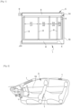
- FIG. 1 is a schematic representation of an exemplary embodiment of a radiant panel according to an exemplary embodiment of the invention
- FIG. 2 is a schematic representation of components including the radiant panel of the invention.
- FIG. 3 is a schematic representation of another example of the invention.
- FIG. 4 is a schematic representation of another example of the invention.
- FIG. 1 represents radiant panel 1, forming a heating structure within the meaning of the invention, arranged to be installed inside a passenger compartment 3 of a vehicle.
- the radiant panel 1 comprises a resistive layer 4 arranged to produce a thermal release when this layer 4 is crossed by an electric current.
- the resistive layer 4 is, for example, an acrylic paint filled with conductive or semi-conductive particles.
- the conductive filler is, for example, in the form of carbon and graphite flakes.
- This panel 1 further comprises an electrode network 5 comprising a plurality of contact electrodes 6 arranged to be in electrical contact with the resistive layer 4 to cause electric current to flow through this resistive layer 4.
- These contact electrodes 6 are arranged with an inter-distance D1, D2 ... Di between successive electrodes, inter-distance which is variable.
- These contact electrodes 6 are rectilinear and parallel to each other in the example described.
- the electrode network 5 comprises distribution electrodes 8 arranged to conduct electric current, one of these electrodes 8 being connected from an electrical source 9, for example of positive electrical polarity, to the contact electrodes 6.
- the other distribution electrode 8 is connected to the other polarity, being for example connected to a ground.
- the electric current thus passes through a distribution electrode 8, which distributes it to the contact electrodes 6.
- the current then flows through the resistive layer 4 before being collected by the contact electrodes 6 connected to the other distribution electrode 8.
- the distribution electrodes 8 are rectilinear over part of their length, or even their entire length, and the contact electrodes 6 which are associated with these distribution electrodes 8 are connected perpendicularly to this associated distribution electrode 8.
- the electrode network 5 comprises two distribution electrodes 8 which are parallel to each other, and their associated contact electrodes 6 are arranged between these two distribution electrodes 8 and are alternated with an inter-distance D1, D2.. Di which decreases in relation to the decrease in the voltage U1, U2... Ui present between the pairs of electrodes 6 so as to maintain the electrical power between the pairs of contact electrodes substantially uniform.
- D1>D2>D3> D4 we have D1>U2>U3> U4 for the voltages between the electrodes 6.
- the resistive layer 4 is a layer deposited on a substrate 16, in particular by screen printing, this resistive layer 4 extending in particular between the two distribution electrodes 8 associated with the group of contact electrodes.
- the substrate 16 is for example made of non-woven fabric, and is flexible and supple.
- a motor vehicle passenger compartment component 19 in particular a component to be integrated into a door of the vehicle, is provided with a radiant panel 1. Several components can be reviewed in the passenger compartment.
- the component 19 may comprise a decorative layer applied to the radiant panel.
- the decorative layer may, for example, be impermeable to air, for example being leather.
- the distribution electrodes 8 may, if desired, have more complex shapes, for example with one or more rounded elbows connecting rectilinear portions.
- the substrate can be a sheet or a canvas for example.
- the contact electrodes 6 and their associated distribution electrodes 8 are arranged in the manner of nested combs.
Landscapes
- Physics & Mathematics (AREA)
- Thermal Sciences (AREA)
- Engineering & Computer Science (AREA)
- Mechanical Engineering (AREA)
- Resistance Heating (AREA)
- Air-Conditioning For Vehicles (AREA)
Claims (9)
- Heizstruktur (30), insbesondere flexibel oder biegsam, die insbesondere dazu bestimmt ist, innerhalb eines Innenraums eines Fahrzeugs eingebaut zu werden, wobei diese Struktur insbesondere eine Strahlungsplatte ist, wobei die Heizstruktur (30) mindestens eine resistive Schicht umfasst, die dazu ausgebildet ist, eine Wärmeabgabe zu erzeugen, wenn diese Schicht (31) von einem elektrischen Strom durchflossen wird, wobei diese Struktur ferner ein Elektrodenarray (32) umfasst, das eine Mehrzahl von Kontaktelektroden (33) beinhaltet, die dazu ausgebildet sind, mit der resistiven Schicht in elektrischem Kontakt zu sein, um elektrischen Strom in dieser resistiven Schicht fließen zu lassen, wobei mindestens zwei dieser Kontaktelektroden in Kontakt mit einem Bereich der resistiven Schicht (31) sind, wobei diese beiden Kontaktelektroden einander gegenüber liegen, so dass elektrischer Strom von einer dieser Elektroden über diesen Bereich der resistiven Schicht zu der anderen der Kontaktelektroden fließen kann, wobei die Heizstruktur Elektroden mit zwei an einen Bereich der resistiven Schicht angrenzenden Rändern beinhaltet und wobei diese beiden Ränder der Elektrode eine axiale Symmetrie (DD) aufweisen, dadurch gekennzeichnet, dass diese beiden den Bereich säumenden Kontaktelektroden (33) eine Form aufweisen, die so gewählt ist, dass sich die beiden Elektroden wechselseitig über einen Abschnitt der Elektroden nähern und an den Enden dieser Elektroden weiter entfernt bleiben, und jeder dieser Ränder eine Konkavität aufweist, die jeweils zu dem anderen Rand hin gerichtet ist.
- Heizstruktur nach dem vorhergehenden Anspruch, wobei der elektrische Strom in zwei Abgabeelektroden (42) in entgegengesetzte Richtung fließt.
- Heizstruktur nach einem der vorhergehenden Ansprüche, wobei der Abstand zwischen den beiden Kontaktelektroden (33) in jeweiligen zentralen Abschnitten der beiden Elektroden, insbesondere im Wesentlichen in der Mitte dieser Elektroden, am kleinsten ist.
- Heizstruktur nach einem der vorhergehenden Ansprüche, wobei die Ränder (44) mindestens einer der Elektroden eine Konkavität beinhalten, die entgegengesetzt zu der gegenüber liegenden anderen Elektrode ausgerichtet ist.
- Heizstruktur nach einem der vorhergehenden Ansprüche, wobei mindestens einer der Ränder (44) gerundet ist.
- Heizstruktur nach einem der vorhergehenden Ansprüche, wobei mindestens einer der Ränder (44) Abschnitte aus Geradensegmenten aufweist.
- Heizstruktur nach einem der vorhergehenden Ansprüche, wobei einer der Ränder der Elektrode gerade (49) ist und der andere Rand eine nicht gerade Form, insbesondere gerundet oder aus Geradensegmenten, insbesondere aus einer Dreieckspitze, aufweist.
- Heizstruktur nach einem der vorhergehenden Ansprüche, wobei die beiden Elektroden eine Symmetrie in Bezug auf eine Symmetrieachse (DS) über den überwiegenden Teil ihrer Länge aufweisen.
- Heizstruktur nach einem der vorhergehenden Ansprüche, wobei die Kontaktelektroden mit den variablen Abständen mit Abgabeelektroden (42), insbesondere parallelen, verbunden sind, die so ausgebildet sind, dass die Richtung des Stroms, die darin fließen, entgegengesetzt sind.
Applications Claiming Priority (2)
| Application Number | Priority Date | Filing Date | Title |
|---|---|---|---|
| FR1910330A FR3101224B1 (fr) | 2019-09-19 | 2019-09-19 | Structure chauffante pour véhicule automobile |
| PCT/FR2020/051549 WO2021053283A1 (fr) | 2019-09-19 | 2020-09-08 | Structure chauffante pour vehicule automobile |
Publications (2)
| Publication Number | Publication Date |
|---|---|
| EP4032371A1 EP4032371A1 (de) | 2022-07-27 |
| EP4032371B1 true EP4032371B1 (de) | 2025-07-09 |
Family
ID=68425146
Family Applications (1)
| Application Number | Title | Priority Date | Filing Date |
|---|---|---|---|
| EP20780248.9A Active EP4032371B1 (de) | 2019-09-19 | 2020-09-08 | Heizstruktur für ein kraftfahrzeug |
Country Status (5)
| Country | Link |
|---|---|
| US (1) | US20220410662A1 (de) |
| EP (1) | EP4032371B1 (de) |
| CN (1) | CN114731740B (de) |
| FR (1) | FR3101224B1 (de) |
| WO (1) | WO2021053283A1 (de) |
Family Cites Families (8)
| Publication number | Priority date | Publication date | Assignee | Title |
|---|---|---|---|---|
| US4034207A (en) * | 1976-01-23 | 1977-07-05 | Murata Manufacturing Co., Ltd. | Positive temperature coefficient semiconductor heating element |
| EP0582734A1 (de) * | 1992-08-11 | 1994-02-16 | LEDA Logarithmic Electrical Devices for Automation S.r.l. | Elektrisch beheizter Sitz für Kraftfahrzeuge |
| DE102012208534A1 (de) * | 2012-05-22 | 2013-11-28 | Lisa Dräxlmaier GmbH | Interieurbauteil mit Wärmestrahler |
| JP5983495B2 (ja) | 2013-03-28 | 2016-08-31 | 株式会社デンソー | 輻射ヒータ装置 |
| JP6245101B2 (ja) * | 2014-07-22 | 2017-12-13 | 株式会社デンソー | 輻射ヒータ装置 |
| KR20160070869A (ko) * | 2014-12-10 | 2016-06-21 | 현대자동차주식회사 | 차량의 히팅패널 |
| CN104883760B (zh) * | 2015-04-24 | 2017-01-18 | 深圳烯旺新材料科技股份有限公司 | 一种低电压透明电热膜 |
| FR3064874B1 (fr) * | 2017-03-30 | 2021-01-08 | Valeo Systemes Thermiques | Panneau radiant comprenant un organe modulant la puissance de chauffe |
-
2019
- 2019-09-19 FR FR1910330A patent/FR3101224B1/fr active Active
-
2020
- 2020-09-08 WO PCT/FR2020/051549 patent/WO2021053283A1/fr not_active Ceased
- 2020-09-08 US US17/760,978 patent/US20220410662A1/en active Pending
- 2020-09-08 EP EP20780248.9A patent/EP4032371B1/de active Active
- 2020-09-08 CN CN202080065142.XA patent/CN114731740B/zh active Active
Also Published As
| Publication number | Publication date |
|---|---|
| CN114731740A (zh) | 2022-07-08 |
| WO2021053283A1 (fr) | 2021-03-25 |
| FR3101224B1 (fr) | 2023-05-26 |
| CN114731740B (zh) | 2025-11-07 |
| FR3101224A1 (fr) | 2021-03-26 |
| US20220410662A1 (en) | 2022-12-29 |
| EP4032371A1 (de) | 2022-07-27 |
Similar Documents
| Publication | Publication Date | Title |
|---|---|---|
| EP1454509B1 (de) | Beheizbare scheibe versehen mit einer elektroleitenden beschichtung | |
| EP3969300A1 (de) | Heizstruktur für ein kraftfahrzeug | |
| FR3099334A1 (fr) | Structure chauffante pour véhicule automobile | |
| EP4449816A1 (de) | Heizvorrichtung für einen fahrzeuginnenraum | |
| DE102012000977A1 (de) | Heizeinrichtung für komplex geformte Oberflächen | |
| WO2020065192A1 (fr) | Panneau radiant destine a etre installe a l'interieur d'un habitacle de vehicule | |
| EP4032371A1 (de) | Heizstruktur für ein kraftfahrzeug | |
| FR3102908A1 (fr) | Structure chauffante pour véhicule automobile | |
| FR3101283A1 (fr) | Structure chauffante pour véhicule automobile | |
| FR3116408A1 (fr) | Structure chauffante pour véhicule automobile | |
| US7967458B2 (en) | Mirror assembly with single heating element for multiple surfaces | |
| FR3064874A1 (fr) | Panneau radiant comprenant un organe modulant la puissance de chauffe | |
| FR3095734A1 (fr) | Structure chauffante pour véhicule automobile | |
| EP3829906A1 (de) | Strahlungsschirm | |
| FR2678563A1 (fr) | Chauffage pour siege d'automobile, en particulier chauffage pouvant s'installer apres coup sur un siege d'automobile. | |
| WO2025026739A1 (fr) | Structure chauffante, notamment pour habitacle de véhicule | |
| WO2021001625A1 (fr) | Structure chauffante pour vehicule automobile | |
| WO2018197780A1 (fr) | Dispositif de chauffage pour un véhicule automobile | |
| EP3535158B1 (de) | Seat or backrest upholstery of an automobile seat | |
| WO2025026784A1 (fr) | Structure chauffante destinée à être installée à l'intérieur d'un habitacle d'un véhicule | |
| WO2020025876A1 (fr) | Panneau radiant | |
| FR3096218A1 (fr) | panneau radiant pour habitacle de véhicule automobile | |
| FR3074456A1 (fr) | Dispositif de regulation thermique pour siege de vehicule | |
| WO2004066680A1 (fr) | Element en plaque avec un chauffage en couche | |
| FR3084292A1 (fr) | Panneau radiant |
Legal Events
| Date | Code | Title | Description |
|---|---|---|---|
| STAA | Information on the status of an ep patent application or granted ep patent |
Free format text: STATUS: UNKNOWN |
|
| STAA | Information on the status of an ep patent application or granted ep patent |
Free format text: STATUS: THE INTERNATIONAL PUBLICATION HAS BEEN MADE |
|
| PUAI | Public reference made under article 153(3) epc to a published international application that has entered the european phase |
Free format text: ORIGINAL CODE: 0009012 |
|
| STAA | Information on the status of an ep patent application or granted ep patent |
Free format text: STATUS: REQUEST FOR EXAMINATION WAS MADE |
|
| 17P | Request for examination filed |
Effective date: 20220415 |
|
| AK | Designated contracting states |
Kind code of ref document: A1 Designated state(s): AL AT BE BG CH CY CZ DE DK EE ES FI FR GB GR HR HU IE IS IT LI LT LU LV MC MK MT NL NO PL PT RO RS SE SI SK SM TR |
|
| DAV | Request for validation of the european patent (deleted) | ||
| DAX | Request for extension of the european patent (deleted) | ||
| P01 | Opt-out of the competence of the unified patent court (upc) registered |
Effective date: 20230528 |
|
| GRAP | Despatch of communication of intention to grant a patent |
Free format text: ORIGINAL CODE: EPIDOSNIGR1 |
|
| STAA | Information on the status of an ep patent application or granted ep patent |
Free format text: STATUS: GRANT OF PATENT IS INTENDED |
|
| INTG | Intention to grant announced |
Effective date: 20250218 |
|
| RIN1 | Information on inventor provided before grant (corrected) |
Inventor name: GOUTHAM, NAVEEN NAGENDRAN Inventor name: AHIZI, SAMUEL Inventor name: DEVIENNE, NICOLAS |
|
| GRAS | Grant fee paid |
Free format text: ORIGINAL CODE: EPIDOSNIGR3 |
|
| GRAA | (expected) grant |
Free format text: ORIGINAL CODE: 0009210 |
|
| STAA | Information on the status of an ep patent application or granted ep patent |
Free format text: STATUS: THE PATENT HAS BEEN GRANTED |
|
| AK | Designated contracting states |
Kind code of ref document: B1 Designated state(s): AL AT BE BG CH CY CZ DE DK EE ES FI FR GB GR HR HU IE IS IT LI LT LU LV MC MK MT NL NO PL PT RO RS SE SI SK SM TR |
|
| REG | Reference to a national code |
Ref country code: GB Ref legal event code: FG4D Free format text: NOT ENGLISH |
|
| REG | Reference to a national code |
Ref country code: CH Ref legal event code: EP |
|
| REG | Reference to a national code |
Ref country code: IE Ref legal event code: FG4D Free format text: LANGUAGE OF EP DOCUMENT: FRENCH |
|
| REG | Reference to a national code |
Ref country code: DE Ref legal event code: R096 Ref document number: 602020054239 Country of ref document: DE |
|
| PGFP | Annual fee paid to national office [announced via postgrant information from national office to epo] |
Ref country code: DE Payment date: 20250916 Year of fee payment: 6 |
|
| PGFP | Annual fee paid to national office [announced via postgrant information from national office to epo] |
Ref country code: FR Payment date: 20250929 Year of fee payment: 6 |
|
| REG | Reference to a national code |
Ref country code: NL Ref legal event code: MP Effective date: 20250709 |
|
| PG25 | Lapsed in a contracting state [announced via postgrant information from national office to epo] |
Ref country code: PT Free format text: LAPSE BECAUSE OF FAILURE TO SUBMIT A TRANSLATION OF THE DESCRIPTION OR TO PAY THE FEE WITHIN THE PRESCRIBED TIME-LIMIT Effective date: 20251110 |
|
| PG25 | Lapsed in a contracting state [announced via postgrant information from national office to epo] |
Ref country code: NL Free format text: LAPSE BECAUSE OF FAILURE TO SUBMIT A TRANSLATION OF THE DESCRIPTION OR TO PAY THE FEE WITHIN THE PRESCRIBED TIME-LIMIT Effective date: 20250709 |
|
| REG | Reference to a national code |
Ref country code: AT Ref legal event code: MK05 Ref document number: 1813094 Country of ref document: AT Kind code of ref document: T Effective date: 20250709 |
|
| PG25 | Lapsed in a contracting state [announced via postgrant information from national office to epo] |
Ref country code: IS Free format text: LAPSE BECAUSE OF FAILURE TO SUBMIT A TRANSLATION OF THE DESCRIPTION OR TO PAY THE FEE WITHIN THE PRESCRIBED TIME-LIMIT Effective date: 20251109 |
|
| PG25 | Lapsed in a contracting state [announced via postgrant information from national office to epo] |
Ref country code: NO Free format text: LAPSE BECAUSE OF FAILURE TO SUBMIT A TRANSLATION OF THE DESCRIPTION OR TO PAY THE FEE WITHIN THE PRESCRIBED TIME-LIMIT Effective date: 20251009 |
|
| REG | Reference to a national code |
Ref country code: LT Ref legal event code: MG9D |
|
| PG25 | Lapsed in a contracting state [announced via postgrant information from national office to epo] |
Ref country code: AT Free format text: LAPSE BECAUSE OF FAILURE TO SUBMIT A TRANSLATION OF THE DESCRIPTION OR TO PAY THE FEE WITHIN THE PRESCRIBED TIME-LIMIT Effective date: 20250709 |
|
| PG25 | Lapsed in a contracting state [announced via postgrant information from national office to epo] |
Ref country code: FI Free format text: LAPSE BECAUSE OF FAILURE TO SUBMIT A TRANSLATION OF THE DESCRIPTION OR TO PAY THE FEE WITHIN THE PRESCRIBED TIME-LIMIT Effective date: 20250709 |
|
| PG25 | Lapsed in a contracting state [announced via postgrant information from national office to epo] |
Ref country code: HR Free format text: LAPSE BECAUSE OF FAILURE TO SUBMIT A TRANSLATION OF THE DESCRIPTION OR TO PAY THE FEE WITHIN THE PRESCRIBED TIME-LIMIT Effective date: 20250709 |
|
| PG25 | Lapsed in a contracting state [announced via postgrant information from national office to epo] |
Ref country code: GR Free format text: LAPSE BECAUSE OF FAILURE TO SUBMIT A TRANSLATION OF THE DESCRIPTION OR TO PAY THE FEE WITHIN THE PRESCRIBED TIME-LIMIT Effective date: 20251010 |
|
| PG25 | Lapsed in a contracting state [announced via postgrant information from national office to epo] |
Ref country code: SE Free format text: LAPSE BECAUSE OF FAILURE TO SUBMIT A TRANSLATION OF THE DESCRIPTION OR TO PAY THE FEE WITHIN THE PRESCRIBED TIME-LIMIT Effective date: 20250709 |
|
| PG25 | Lapsed in a contracting state [announced via postgrant information from national office to epo] |
Ref country code: LV Free format text: LAPSE BECAUSE OF FAILURE TO SUBMIT A TRANSLATION OF THE DESCRIPTION OR TO PAY THE FEE WITHIN THE PRESCRIBED TIME-LIMIT Effective date: 20250709 |
|
| PG25 | Lapsed in a contracting state [announced via postgrant information from national office to epo] |
Ref country code: BG Free format text: LAPSE BECAUSE OF FAILURE TO SUBMIT A TRANSLATION OF THE DESCRIPTION OR TO PAY THE FEE WITHIN THE PRESCRIBED TIME-LIMIT Effective date: 20250709 Ref country code: PL Free format text: LAPSE BECAUSE OF FAILURE TO SUBMIT A TRANSLATION OF THE DESCRIPTION OR TO PAY THE FEE WITHIN THE PRESCRIBED TIME-LIMIT Effective date: 20250709 |
|
| PG25 | Lapsed in a contracting state [announced via postgrant information from national office to epo] |
Ref country code: RS Free format text: LAPSE BECAUSE OF FAILURE TO SUBMIT A TRANSLATION OF THE DESCRIPTION OR TO PAY THE FEE WITHIN THE PRESCRIBED TIME-LIMIT Effective date: 20251009 |
|
| PG25 | Lapsed in a contracting state [announced via postgrant information from national office to epo] |
Ref country code: ES Free format text: LAPSE BECAUSE OF FAILURE TO SUBMIT A TRANSLATION OF THE DESCRIPTION OR TO PAY THE FEE WITHIN THE PRESCRIBED TIME-LIMIT Effective date: 20250709 |
|
| REG | Reference to a national code |
Ref country code: CH Ref legal event code: W10 Free format text: ST27 STATUS EVENT CODE: U-0-0-W10-W00 (AS PROVIDED BY THE NATIONAL OFFICE) Effective date: 20260218 |
|
| PG25 | Lapsed in a contracting state [announced via postgrant information from national office to epo] |
Ref country code: RO Free format text: LAPSE BECAUSE OF FAILURE TO SUBMIT A TRANSLATION OF THE DESCRIPTION OR TO PAY THE FEE WITHIN THE PRESCRIBED TIME-LIMIT Effective date: 20250709 |
|
| RAP2 | Party data changed (patent owner data changed or rights of a patent transferred) |
Owner name: VALEO ELECTRIFICATION |
|
| PG25 | Lapsed in a contracting state [announced via postgrant information from national office to epo] |
Ref country code: SM Free format text: LAPSE BECAUSE OF FAILURE TO SUBMIT A TRANSLATION OF THE DESCRIPTION OR TO PAY THE FEE WITHIN THE PRESCRIBED TIME-LIMIT Effective date: 20250709 |
|
| PG25 | Lapsed in a contracting state [announced via postgrant information from national office to epo] |
Ref country code: DK Free format text: LAPSE BECAUSE OF FAILURE TO SUBMIT A TRANSLATION OF THE DESCRIPTION OR TO PAY THE FEE WITHIN THE PRESCRIBED TIME-LIMIT Effective date: 20250709 |
|
| PG25 | Lapsed in a contracting state [announced via postgrant information from national office to epo] |
Ref country code: IT Free format text: LAPSE BECAUSE OF FAILURE TO SUBMIT A TRANSLATION OF THE DESCRIPTION OR TO PAY THE FEE WITHIN THE PRESCRIBED TIME-LIMIT Effective date: 20250709 |
|
| PG25 | Lapsed in a contracting state [announced via postgrant information from national office to epo] |
Ref country code: CZ Free format text: LAPSE BECAUSE OF FAILURE TO SUBMIT A TRANSLATION OF THE DESCRIPTION OR TO PAY THE FEE WITHIN THE PRESCRIBED TIME-LIMIT Effective date: 20250709 |
|
| REG | Reference to a national code |
Ref country code: CH Ref legal event code: H13 Free format text: ST27 STATUS EVENT CODE: U-0-0-H10-H13 (AS PROVIDED BY THE NATIONAL OFFICE) Effective date: 20260425 |
|
| PG25 | Lapsed in a contracting state [announced via postgrant information from national office to epo] |
Ref country code: EE Free format text: LAPSE BECAUSE OF FAILURE TO SUBMIT A TRANSLATION OF THE DESCRIPTION OR TO PAY THE FEE WITHIN THE PRESCRIBED TIME-LIMIT Effective date: 20250709 Ref country code: SK Free format text: LAPSE BECAUSE OF FAILURE TO SUBMIT A TRANSLATION OF THE DESCRIPTION OR TO PAY THE FEE WITHIN THE PRESCRIBED TIME-LIMIT Effective date: 20250709 |
|
| PLBE | No opposition filed within time limit |
Free format text: ORIGINAL CODE: 0009261 |
|
| STAA | Information on the status of an ep patent application or granted ep patent |
Free format text: STATUS: NO OPPOSITION FILED WITHIN TIME LIMIT |