EP4032001B1 - Émulateur de barre omnibus pour automobile, navire et aéronef - Google Patents
Émulateur de barre omnibus pour automobile, navire et aéronef Download PDFInfo
- Publication number
- EP4032001B1 EP4032001B1 EP20785839.0A EP20785839A EP4032001B1 EP 4032001 B1 EP4032001 B1 EP 4032001B1 EP 20785839 A EP20785839 A EP 20785839A EP 4032001 B1 EP4032001 B1 EP 4032001B1
- Authority
- EP
- European Patent Office
- Prior art keywords
- computer
- bus
- bus system
- information
- information interface
- Prior art date
- Legal status (The legal status is an assumption and is not a legal conclusion. Google has not performed a legal analysis and makes no representation as to the accuracy of the status listed.)
- Active
Links
Images


Classifications
-
- G—PHYSICS
- G06—COMPUTING OR CALCULATING; COUNTING
- G06F—ELECTRIC DIGITAL DATA PROCESSING
- G06F21/00—Security arrangements for protecting computers, components thereof, programs or data against unauthorised activity
- G06F21/60—Protecting data
- G06F21/604—Tools and structures for managing or administering access control systems
-
- H—ELECTRICITY
- H04—ELECTRIC COMMUNICATION TECHNIQUE
- H04L—TRANSMISSION OF DIGITAL INFORMATION, e.g. TELEGRAPHIC COMMUNICATION
- H04L12/00—Data switching networks
- H04L12/28—Data switching networks characterised by path configuration, e.g. LAN [Local Area Networks] or WAN [Wide Area Networks]
- H04L12/40—Bus networks
- H04L12/40006—Architecture of a communication node
-
- G—PHYSICS
- G06—COMPUTING OR CALCULATING; COUNTING
- G06F—ELECTRIC DIGITAL DATA PROCESSING
- G06F21/00—Security arrangements for protecting computers, components thereof, programs or data against unauthorised activity
- G06F21/70—Protecting specific internal or peripheral components, in which the protection of a component leads to protection of the entire computer
- G06F21/71—Protecting specific internal or peripheral components, in which the protection of a component leads to protection of the entire computer to assure secure computing or processing of information
- G06F21/74—Protecting specific internal or peripheral components, in which the protection of a component leads to protection of the entire computer to assure secure computing or processing of information operating in dual or compartmented mode, i.e. at least one secure mode
-
- G—PHYSICS
- G06—COMPUTING OR CALCULATING; COUNTING
- G06F—ELECTRIC DIGITAL DATA PROCESSING
- G06F21/00—Security arrangements for protecting computers, components thereof, programs or data against unauthorised activity
- G06F21/70—Protecting specific internal or peripheral components, in which the protection of a component leads to protection of the entire computer
- G06F21/82—Protecting input, output or interconnection devices
- G06F21/85—Protecting input, output or interconnection devices interconnection devices, e.g. bus-connected or in-line devices
-
- H—ELECTRICITY
- H04—ELECTRIC COMMUNICATION TECHNIQUE
- H04L—TRANSMISSION OF DIGITAL INFORMATION, e.g. TELEGRAPHIC COMMUNICATION
- H04L12/00—Data switching networks
- H04L12/28—Data switching networks characterised by path configuration, e.g. LAN [Local Area Networks] or WAN [Wide Area Networks]
- H04L12/40—Bus networks
- H04L2012/40267—Bus for use in transportation systems
- H04L2012/40273—Bus for use in transportation systems the transportation system being a vehicle
Definitions
- This application relates to internal bus systems of various devices or systems that are connectable to external networks.
- peripheral devices or systems refers to those devices or systems with an external connection. Such external connections may be through physical connection (e.g., USB connectors, on-board diagnostic (OBD) connectors, etc.) or through the Internet or other various networks (e.g., LTE, Wi-Fi, Bluetooth, LAN, etc.).
- OBD on-board diagnostic
- Examples of devices and systems that use centralized bus systems to connect peripheral devices and mission critical devices include, but are not limited to, transportation devices (e.g., automobiles, naval vessels, aircraft, trains, etc.), heavy industry, etc. are equipped with modem centralized bus systems.
- peripheral devices or systems may include entertainment systems, navigation systems, alarming systems, diagnostic systems, etc.
- mission critical devices or systems may include the engine, brakes, accelerator, fuel injector, etc.
- US 2018/205703 A1 discloses an automotive ECU architecture with two separate buses, one for critical systems and another for non-critical systems.
- the two buses are connected by a firewall/gateway, which applies a set of rules and filters to control the flow of information between the two.
- US 2018/004964 A1 teaches protecting safety-critical automotive ECUs by having multiple communication buses isolated by gateways/bridges applying a set of rules to control the flow of information, which may potentially be malicious.
- a bus emulator device includes a first computer, a second computer, and an information interface.
- the first computer is configured to connect to a main bus system, the first computer includes only write access into the information interface, and the second computer includes only read access into the information interface.
- the main bus system includes at least one mission critical system
- the second computer is configured to simulate the at least one mission critical system In an emulated bus system.
- the emulated bus system includes at least one peripheral system connectable to an external network.
- the bus emulator device includes a tact generator, and the first computer, the second computer, and the information interface run on the tact generator.
- a system includes a first bus system, a second bus system, and a bus emulator device connected to the first bus system and the second bus system.
- the bus emulator device physically isolates the first bus system from the second bus system.
- the first bus system is a main bus system having at least one mission critical system
- the second bus system includes at least one peripheral system connectable to an external network and an emulated system simulating the at least one mission critical system.
- a bus system includes a first system and a second system.
- the first system is at least one physical system, and the bus system is directly connected to the at least one physical system.
- the second system is an emulated system including at least one simulation of a third system.
- a bus emulator device includes an information interface.
- the bus emulator device may be configured to connect to a main bus system and an emulated bus system, and the information interface may define a one-way data exchange between the main bus system and the emulated bus system.
- a bus emulator device includes a first computer, a second computer, and an information interface.
- the first computer is configured to connect to a main bus system, the first computer includes at least write access into the information interface, and the second computer comprises only read access into the information interface. In certain embodiments, the first computer also includes read access into the information interface.
- a bus emulator device includes a first computer, a second computer, and an information interface.
- the first computer is configured to connect to a main bus system, the first computer includes only write access into the information interface, and the second computer includes at least read access into the information interface. In some embodiments, the second computer also includes write access into the information interface.
- a bus emulator device includes a first computer, a second computer, an information interface, and an additional memory.
- the first computer is configured to connect to a main, bus system, and the first computer includes at least write access into the information interface.
- the second computer includes only read access into the information interface.
- the first computer has no access to the additional memory, and the second computer includes read access and write access into the additional memory.
- Certain embodiments of the present invention provide a bus emulator device that includes at least two independent computers that may or may not share memory or part of memory (i.e., at least a first independent computer and a second independent computer) and at least one independent physical memory (or "information interface").
- the first independent computer is connectable to the central or main bus system (also called a "hot-bus") of the transportation device and the second independent computer emulates a bus similar to the main bus system (also called an "emulated bus system" or a "cold bus”).
- main bus also called an "emulated bus system” or a "cold bus”
- the main bus may have a controlled secure network connection (e.g., to an emergency network).
- the first independent computer (connected to the main bus system) (also called the “main computer”) has full access to the main bus and the information on the main bus.
- the second independent computer (also called the “emulation computer”) has only read access to the information of the first independent computer that is connected to the main bus.
- the second independent computer can read current and past status information from the main computer but he cannot modify the information.
- This configuration of the second independent computer may be achieved in a number of different ways.
- the emulation computer may have read access to parts of the memory of the main computer (but does not have delete / modify / write rights).
- the emulation computer may get the information from the main computer as a request from the emulation computer or automatically (i.e., a push from main computer). With this information of the main computer, the emulation computer emulates the main bus, meaning that the emulation computer builds up a "virtual" bus that looks exactly like the main bus. External devices and services may access this emulated bus instead of the main (hot) bus. This allows all external services (navigation, diagnostic, convenient services etc.) to obtain the information they need from the vehicle to deliver their services, but without the capability to modify this information directory. This dramatically lowers the risk for the vehicle to be hijacked and/or manipulated by external sources. Various other suitable configurations may be utilized.
- the main computer can read out this information and check the information for plausibility and safety. In some cases, if the information is safe and passes all safety and security tests, the main computer has the capability to use this information in the hot bus system. In this manner, updates for traffic conditions on the navigation system or other updates are still possible.
- the first independent computer When the bus emulator device is installed with a device having a main bus system (e.g., in an automobile, ship, aircraft, etc.), the first independent computer connects with the main bus system. Any number of critical devices or systems are connected to the main bus system including, but not limited to, the engine, brakes, accelerator, suspension, fuel injection, steering, power steering, navigation, identification (e.g., transponders), etc. While the first independent computer is connected with the main bus system, the first independent computer writes (in real time or as otherwise desired) all needed data or information from those critical devices or systems (e.g., engine conditions, motor parameters, speed, etc.) into the information interface.
- critical devices or systems e.g., engine conditions, motor parameters, speed, etc.
- the second independent computer (handling the emulated bus system) reads this data from the information interface (in real time or as otherwise desired) and uses the read data to emulate the main bus system in the emulated bus system.
- the emulated bus system may look the same as the main bus system but without a physical connection into the main bus system. Additional peripheral devices or systems including, but not limited to, smart navigation systems, entertainment systems, internet access systems, OBD connectors, interfaces with USB connectors, mobile phone connections, alarming systems, etc., are physically connected to the emulated bus system and do not have any physical connection to the main bus system.
- bus emulator systems and devices described herein provide a cost-efficient and cost-effective solution to increase safety of central bus systems of devices and can be integrated without major modification to new and existing central bus systems.
- a system creates a second bus system to separate mission critical systems from other systems that may have additional connection.
- the system physically isolates the mission critical bus system of a vehicle, vessel, plane or any other device / industrial unit.
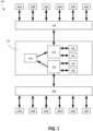
- FIG. 1 is a diagram illustrating an example of a bus emulator device 102 provided in a transportation device 100.
- the transportation device 100 includes one or more mission critical systems or devices 104A-F.
- mission critical systems or devices 104 may include, but are not limited to, the engine, brakes, accelerator, fuel injector, etc.
- the mission critical systems or devices 104 may be different devices or systems, and the listed mission critical devices or systems or the characterization of devices or systems as "mission critical" should not be considered limiting on the current disclosure.
- the number of mission critical devices 104 should not be considered limiting on the current disclosure.
- the transportation device 100 may also include one or more peripheral systems or devices 106A-F.
- peripheral devices may include, but are not limited to, navigation systems, radio, USB connectors, OBD connectors, entertainment systems, alarm systems, etc.
- the peripheral systems or devices 106 may be different devices or systems, and the listed peripheral devices or systems or the characterization of devices or systems as "peripheral" should not be considered limiting on the current disclosure.
- the number of peripheral devices 106 should not be considered limiting on the current disclosure.
- the mission critical devices 104A-F are connected into a main bus system 108 such that a normal exchange of data and information among the mission critical devices 104 is possible.
- peripheral devices 106A-F are connected to the bus emulator device 102 such that they have read access to the information of the main bus system 108 (from the mission critical devices) but cannot modify the information. In some examples, the peripheral devices 106 are not physically connected into the main bus system 108.
- the bus emulator device 102 includes a first independent computer 110, a second independent computer 112, and the independent physical memory or information interface 114. While a single bus emulator device 102 is illustrated, it will be appreciated that any number of devices 102 could be utilized. In some cases, each mission critical device 104 may have a dedicated emulator, although it need not in other examples. In various examples, the computer 110, the computer 112, and the information interface 114 run on the same tact generator, although they need not in other examples.
- the first independent computer 110 may be associated and in communication with Boot ROM 116 and a memory subsystem 118.
- the second independent computer 112 may be associated and in communication with Boot ROM 120 and a memory subsystem 122.
- the independent computers 110, 112 may be general purpose processing units, processors specially designed for the bus emulator, a field-programmable gate array (FPGA), an application-specific integrated circuit (ASIC), a microprocessor, etc.
- the information interface 114 and memory subsystems 118, 122 may include a long-term storage memory and/or a short-term working memory and may be various suitable types of computer-readable medium including, but not limited to, include magnetic disks, memory chips, ROM, random-access memory (RAM), an ASIC, a configured processor, optical storage, or any other medium from which a processor can read the instructions.
- the information interface 114 is shared memory where the first independent computer 110 has at least write capabilities (and optionally has read capabilities) and the second independent computer 112 only has read capabilities.
- the information interface 114 may always include the information from the hot bus system 108 (via the first independent computer 110) so that the second independent computer 112 can read the information to emulate the cold bus system 124.
- the information interface 114 may be a memory that is only controlled by the second independent computer 112, and the second independent computer 112 may use it to directly emulate the cold bus system 124.
- the second independent computer 112 may get the information by push from the first independent computer 110 or upon request.
- the first independent computer 110 and the second independent computer 112 may each include at least one additional memory.
- the first independent computer 110 may build up the information on the information interface 114, the second independent computer 112 may copy the information from the information interface 114 to its additional memory, and the second independent computer 112 may then allow peripheral devices to read and/or modify the content on the additional memory.
- the first independent computer 110, the second independent computer 112, and the information interface 114 are arranged and connected such that the second independent computer 112 can read current and past status information provided by or on the first independent computer 110 but cannot modify such information.
- FIG. 1 illustrates one configuration of the first independent computer 110, the second independent computer 112, and the information interface 114 where the second independent computer 112 can read current and past status information provided by or on the first independent computer 110 but cannot modify such information.
- the first independent computer 110 has write access to the information interface 114 but not read access.
- the first independent computer 110 has full access to the information interface 114 (e.g., read, write, delete, modify, etc.).
- the second independent computer 112 has read access to the information interface 114 but not write access.
- the information interface 114 is a one-way memory for data exchange between the main bus system 108 and an emulated bus system 124.
- the second independent computer 112 may read the information interface 114 upon a request and/or automatically (e.g., as a push).
- the first independent computer 110 writes all needed information and data from the mission critical devices 104A-F into the information interface 114.
- the second independent computer 112 reads the information and data from the information interface 114 and uses the data and information to emulate the main bus system 108 in the emulated bus system 124.
- the emulated bus system 124 may not have a physical (or direct) connection into the main bus system 108. In other words, the emulated bus system 124 is only able to indirectly access information and data from the main bus system 108 via the bus emulator device 102.
- the emulated bus system 124 may look the same or substantially the same as the main bus system 108 (although it need not be), meaning that the emulated bus system 124 can simulate each of the mission critical devices 104A-F.
- the peripheral devices 106A-F may physically connect into the emulated bus system 124, but the peripheral devices 106A-F do not have a physical connection to the main bus system 108.
- the emulated bus system 124 and systems or devices connected to the emulated bus system 124) cannot manipulate the main bus system 108 (and systems or devices connected to the main bus system 108).
- providing the first independent computer 110 such that can only write into the information interface may provide an additional layer of security between the two computers. However, in other examples and as discussed in detail below, the first independent computer 110 may have full access to the information interface.
- FIG. 2 illustrates a non-limiting example of a possible software or firmware architecture on the emulated bus side.
- This software may be installed in the Boot ROM 120 or other computer readable medium associated with the second independent computer 112.
- the software architecture can be programmed in various suitable programming languages as desired.
- the peripheral devices 106A-F may not realize that there is no physical or direct connection to the mission critical devices 104A-F.
- This configuration may make it possible to install the bus emulator device in existing environments while maintaining compatibility.
- Such a configuration allows the peripheral devices 106A-F to still use the information from the mission critical devices 104A-F without being able to manipulate the mission critical devices 104A-F.
- an OBD connector (a peripheral device) may connect with the emulated bus system 124 to perform various diagnostics on the vehicle, but the OBD connector cannot be used to manipulate the mission critical devices 104. Updating of all peripheral devices is still possible with the bus emulator device 102.
- the emulated bus system 124 combines physical systems or devices (i.e., the peripheral devices 106) and virtual or emulated systems or devices (i.e., the simulated mission critical devices from reading the information interface 114).
- the bus emulator device 102 optionally includes a second shared memory space 126 (or second information interface).
- the second shared memory space 126 may allow for the write back of selected registers into the main bus system 108. Such selected registers may be predefined and controlled to limit the manipulation of the hot bus system 108 and the mission critical devices 104.
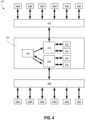
- FIG. 4 illustrates another configuration of the first independent computer 110, the second independent computer 112, and the information interface 114 where the second independent computer 112 can read current and past status information provided by or on the first independent computer 110 but cannot modify such information.
- the first independent computer 110 has full access to the information interface 114 (e.g., read, write, delete, modify, etc.).
- the information interface 114 is a shared memory where the first independent computer 110 has read and write capabilities, and the second independent computer 112 only has read capabilities.
- the information interface 114 may always include the information from the hot bus system 108.
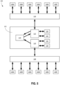
- FIG. 5 illustrates another configuration of the first independent computer 110, the second independent computer 112, and the information interface 114 where the second independent computer 112 can read current and past status information provided by or on the first independent computer 110 but cannot modify such information to control the hot bus system 108.
- the first independent computer 110 only has write access
- the second independent computer 112 has both read and write access.
- the information interface 114 is controlled by the second independent computer 112, and the second independent computer can use the information interface 114 to directly emulate the cold bus 124.
- the information interface 114 may or may not always include current or past information of the hot bus system 108.
- FIG. 6 illustrates another configuration of the first independent computer 110, the second independent computer 112, and the information interface 114 where the second independent computer 112 can read current and past status information provided by or on the first independent computer 110 but cannot modify such information to control the hot bus system 108.
- the second independent computer 112 has an additional memory 119.
- the additional memory 119 may be the same type of memory as the information interface 114 or a different type of memory as desired.
- the first independent computer 110 may similarly have an additional memory, although it need not in other examples.
- the first independent computer 110 is illustrated with only write access to the information interface 114, in other examples the first independent computer 110 may have full access to the information interface 114.
- the first independent computer 110 builds up the information about the hot bus system 108 on at least the information interface 114.
- the second independent computer 112 copies the information from the information interface 114 to the additional memory 119.
- the peripheral devices 106 may read and/or modify the information on the additional memory 119 as desired.
Landscapes
- Engineering & Computer Science (AREA)
- Theoretical Computer Science (AREA)
- Computer Hardware Design (AREA)
- Physics & Mathematics (AREA)
- Computer Security & Cryptography (AREA)
- Software Systems (AREA)
- General Engineering & Computer Science (AREA)
- General Physics & Mathematics (AREA)
- Computer Networks & Wireless Communication (AREA)
- Signal Processing (AREA)
- Mathematical Physics (AREA)
- Automation & Control Theory (AREA)
- Health & Medical Sciences (AREA)
- Bioethics (AREA)
- General Health & Medical Sciences (AREA)
- Bus Control (AREA)
Claims (7)
- Dispositif émulateur de bus (102) comportant :un premier ordinateur (110) ;un second ordinateur (112) ; etune interface d'informations (114),dans lequel le premier ordinateur est configuré pour se connecter à un système de bus principal (108) comportant au moins un dispositif vital (104) et des informations et des données d'écriture provenant du au moins un dispositif vital dans l'interface d'informations, et le second ordinateur est configuré pour lire les informations et les données à partir de l'interface d'informations et utiliser les données et les informations pour émuler le système de bus principal dans un système de bus émulé (124)dans lequel i) soit le premier ordinateur comporte au moins un accès en écriture dans l'interface d'informations et le second ordinateur comporte un accès en lecture seule dans l'interface d'informations,ii) soit le premier ordinateur comporte un accès en écriture seule dans l'interface d'informations et le second ordinateur comporte au moins un accès en lecture dans l'interface d'informations.
- Dispositif émulateur de bus (102) selon la revendication 1, dans lequel le second ordinateur (112) comporte un accès en lecture seule dans l'interface d'informations (114) et le premier ordinateur (110) comporte au moins un accès en lecture et un accès en écriture dans l'interface d'informations.
- Dispositif émulateur de bus selon la revendication 1, dans lequel le premier ordinateur (110) comporte un accès en écriture seule dans l'interface d'informations (114) et le second ordinateur comporte au moins un accès en lecture et en écriture dans l'interface d'informations.
- Dispositif émulateur de bus (102) selon l'une quelconque des revendications 1 à 3, dans lequel le système de bus émulé comporte au moins un système périphérique pouvant être connecté à un réseau externe.
- Dispositif émulateur de bus (102) selon l'une quelconque des revendications 1 à 3, comportant en outre un générateur tactile, et dans lequel le premier ordinateur (110), le second ordinateur (112) et l'interface d'informations (114) s'exécutent sur le générateur tactile.
- Dispositif émulateur de bus (102) selon l'une quelconque des revendications 1 à 3 ou 5, comportant en outre :une mémoire supplémentaire (119),dans lequel le premier ordinateur (110) n'a aucun accès à la mémoire supplémentaire, etdans lequel le second ordinateur (112) comporte un accès en lecture et un accès en écriture dans la mémoire supplémentaire.
- Système (100) comportant :un premier système de bus (108) ;un second système de bus (124) ; etle dispositif émulateur de bus (102) selon l'une quelconque des revendications précédentes connecté au premier système de bus et au second système de bus, dans lequel le dispositif émulateur de bus isole physiquement le premier système de bus du second système de bus, et dans lequel le premier système de bus est un système de bus principal et le second système de bus est un système de bus émulé.
Applications Claiming Priority (2)
| Application Number | Priority Date | Filing Date | Title |
|---|---|---|---|
| US201962903711P | 2019-09-20 | 2019-09-20 | |
| PCT/IB2020/058586 WO2021053517A1 (fr) | 2019-09-20 | 2020-09-16 | Émulateur de barre omnibus pour automobile, navire et aéronef |
Publications (3)
| Publication Number | Publication Date |
|---|---|
| EP4032001A1 EP4032001A1 (fr) | 2022-07-27 |
| EP4032001C0 EP4032001C0 (fr) | 2024-10-30 |
| EP4032001B1 true EP4032001B1 (fr) | 2024-10-30 |
Family
ID=72717892
Family Applications (1)
| Application Number | Title | Priority Date | Filing Date |
|---|---|---|---|
| EP20785839.0A Active EP4032001B1 (fr) | 2019-09-20 | 2020-09-16 | Émulateur de barre omnibus pour automobile, navire et aéronef |
Country Status (5)
| Country | Link |
|---|---|
| US (1) | US11956096B2 (fr) |
| EP (1) | EP4032001B1 (fr) |
| CA (1) | CA3151869A1 (fr) |
| ES (1) | ES3006464T3 (fr) |
| WO (1) | WO2021053517A1 (fr) |
Families Citing this family (2)
| Publication number | Priority date | Publication date | Assignee | Title |
|---|---|---|---|---|
| ES3006464T3 (en) | 2019-09-20 | 2025-03-18 | Rockpatech Ag | Automotive, naval, and aircraft bus-emulator |
| US12497194B2 (en) | 2023-09-29 | 2025-12-16 | General Electric Company | Aircraft monitoring system |
Family Cites Families (10)
| Publication number | Priority date | Publication date | Assignee | Title |
|---|---|---|---|---|
| CN1564997A (zh) * | 2001-09-07 | 2005-01-12 | 米-茵有限公司 | 操作装置 |
| DE10241545A1 (de) * | 2002-09-05 | 2004-03-25 | Gkss-Forschungszentrum Geesthacht Gmbh | Vorrichtung zur Überführung eines kontinuierlichen Flüssigkeitsstroms in einen Strom aus Flüssigkeitströpfchen |
| US8419608B2 (en) * | 2007-09-26 | 2013-04-16 | Mega-Wave-Gmbh | Apparatus for producing fields for treatment of bodily parts of living organisms for healing purposes |
| EP3651437B1 (fr) * | 2012-03-29 | 2021-02-24 | Arilou Information Security Technologies Ltd. | Protection d'un système électronique de véhicule |
| US9257240B2 (en) * | 2012-06-26 | 2016-02-09 | Samsung Electronics Co., Ltd. | Key assembly and electronic device having the same |
| JP2015170282A (ja) * | 2014-03-10 | 2015-09-28 | トヨタ自動車株式会社 | 車両用操作装置 |
| US10666615B2 (en) * | 2015-08-03 | 2020-05-26 | Sectigo, Inc. | Method for detecting, blocking and reporting cyber-attacks against automotive electronic control units |
| KR101969264B1 (ko) * | 2018-08-27 | 2019-04-16 | 주식회사 엔디소프트 | 컨텐츠 검색용 단어를 특수식별기호와 함께 자동 삽입하는 방법 |
| US20200145338A1 (en) * | 2018-11-04 | 2020-05-07 | Terafence Ltd. | Application specific gateway device |
| ES3006464T3 (en) | 2019-09-20 | 2025-03-18 | Rockpatech Ag | Automotive, naval, and aircraft bus-emulator |
-
2020
- 2020-09-16 ES ES20785839T patent/ES3006464T3/es active Active
- 2020-09-16 EP EP20785839.0A patent/EP4032001B1/fr active Active
- 2020-09-16 CA CA3151869A patent/CA3151869A1/fr active Pending
- 2020-09-16 US US17/762,076 patent/US11956096B2/en active Active
- 2020-09-16 WO PCT/IB2020/058586 patent/WO2021053517A1/fr not_active Ceased
Also Published As
| Publication number | Publication date |
|---|---|
| CA3151869A1 (fr) | 2021-03-25 |
| EP4032001C0 (fr) | 2024-10-30 |
| US11956096B2 (en) | 2024-04-09 |
| WO2021053517A1 (fr) | 2021-03-25 |
| EP4032001A1 (fr) | 2022-07-27 |
| US20220393905A1 (en) | 2022-12-08 |
| ES3006464T3 (en) | 2025-03-18 |
Similar Documents
| Publication | Publication Date | Title |
|---|---|---|
| JP7685184B2 (ja) | セキュアロックダウンを実装するように構成された関連装置を有する特別にプログラムされたコンピューティングシステムおよびその使用方法 | |
| CN105871830B (zh) | 一种汽车车载信息系统的防火墙 | |
| Macher et al. | Integrated safety and security development in the automotive domain | |
| EP3393088B1 (fr) | Système et procédé de surveillance du trafic de données sur un bus de données mil-std-1553 | |
| EP4032001B1 (fr) | Émulateur de barre omnibus pour automobile, navire et aéronef | |
| US20220171611A1 (en) | Electronic control unit, software update method, software update program product and electronic control system | |
| CN114802052A (zh) | 用于车载网络入侵检测系统的可信环境自学习方法及系统 | |
| JP2013009370A (ja) | 車両ネットワーク用の安全なデータストア | |
| WO2019004638A1 (fr) | Procédé et système permettant de régler une fonction de sécurité de dispositif de commande électronique | |
| CN112537316A (zh) | 用于至少部分自动化地引导机动车的方法 | |
| US10958472B2 (en) | Direct access to bus signals in a motor vehicle | |
| US20220308858A1 (en) | Vehicle program update management system, reprogramming terminal, and vehicle program update management method | |
| CN213186571U (zh) | 一种应用于车载网络中的ecu安全升级系统 | |
| US20260006029A1 (en) | Management of vehicle network access | |
| US10581632B2 (en) | Data transfer filter | |
| WO2025045019A1 (fr) | Procédé de commande et appareil | |
| US20250053636A1 (en) | Computer system protection | |
| CN119226152A (zh) | 车机系统的安全策略构建方法、装置、设备及车辆 | |
| CN120226005A (zh) | 识别用于装置、尤其是用于运输工具的具有区分隔的计算机系统中的外部干预 | |
| Siddiqui et al. | Embedded Policing and Policy Enforcement based Security in the era of Digital-Physical Convergence for Next-Generation Vehicular Electronics | |
| CN120872389A (zh) | 车机应用程序更新方法及其系统、车辆 |
Legal Events
| Date | Code | Title | Description |
|---|---|---|---|
| STAA | Information on the status of an ep patent application or granted ep patent |
Free format text: STATUS: UNKNOWN |
|
| STAA | Information on the status of an ep patent application or granted ep patent |
Free format text: STATUS: THE INTERNATIONAL PUBLICATION HAS BEEN MADE |
|
| PUAI | Public reference made under article 153(3) epc to a published international application that has entered the european phase |
Free format text: ORIGINAL CODE: 0009012 |
|
| STAA | Information on the status of an ep patent application or granted ep patent |
Free format text: STATUS: REQUEST FOR EXAMINATION WAS MADE |
|
| 17P | Request for examination filed |
Effective date: 20220419 |
|
| AK | Designated contracting states |
Kind code of ref document: A1 Designated state(s): AL AT BE BG CH CY CZ DE DK EE ES FI FR GB GR HR HU IE IS IT LI LT LU LV MC MK MT NL NO PL PT RO RS SE SI SK SM TR |
|
| DAV | Request for validation of the european patent (deleted) | ||
| DAX | Request for extension of the european patent (deleted) | ||
| RAP1 | Party data changed (applicant data changed or rights of an application transferred) |
Owner name: ROCKPATECH AG |
|
| RIN1 | Information on inventor provided before grant (corrected) |
Inventor name: KUSTER, MARTIN |
|
| GRAP | Despatch of communication of intention to grant a patent |
Free format text: ORIGINAL CODE: EPIDOSNIGR1 |
|
| STAA | Information on the status of an ep patent application or granted ep patent |
Free format text: STATUS: GRANT OF PATENT IS INTENDED |
|
| INTG | Intention to grant announced |
Effective date: 20240524 |
|
| GRAS | Grant fee paid |
Free format text: ORIGINAL CODE: EPIDOSNIGR3 |
|
| GRAA | (expected) grant |
Free format text: ORIGINAL CODE: 0009210 |
|
| STAA | Information on the status of an ep patent application or granted ep patent |
Free format text: STATUS: THE PATENT HAS BEEN GRANTED |
|
| AK | Designated contracting states |
Kind code of ref document: B1 Designated state(s): AL AT BE BG CH CY CZ DE DK EE ES FI FR GB GR HR HU IE IS IT LI LT LU LV MC MK MT NL NO PL PT RO RS SE SI SK SM TR |
|
| REG | Reference to a national code |
Ref country code: GB Ref legal event code: FG4D |
|
| REG | Reference to a national code |
Ref country code: CH Ref legal event code: EP |
|
| REG | Reference to a national code |
Ref country code: DE Ref legal event code: R096 Ref document number: 602020040402 Country of ref document: DE |
|
| REG | Reference to a national code |
Ref country code: IE Ref legal event code: FG4D |
|
| U01 | Request for unitary effect filed |
Effective date: 20241127 |
|
| U07 | Unitary effect registered |
Designated state(s): AT BE BG DE DK EE FI FR IT LT LU LV MT NL PT RO SE SI Effective date: 20241203 |
|
| REG | Reference to a national code |
Ref country code: ES Ref legal event code: FG2A Ref document number: 3006464 Country of ref document: ES Kind code of ref document: T3 Effective date: 20250318 |
|
| PG25 | Lapsed in a contracting state [announced via postgrant information from national office to epo] |
Ref country code: IS Free format text: LAPSE BECAUSE OF FAILURE TO SUBMIT A TRANSLATION OF THE DESCRIPTION OR TO PAY THE FEE WITHIN THE PRESCRIBED TIME-LIMIT Effective date: 20250228 Ref country code: HR Free format text: LAPSE BECAUSE OF FAILURE TO SUBMIT A TRANSLATION OF THE DESCRIPTION OR TO PAY THE FEE WITHIN THE PRESCRIBED TIME-LIMIT Effective date: 20241030 |
|
| PG25 | Lapsed in a contracting state [announced via postgrant information from national office to epo] |
Ref country code: NO Free format text: LAPSE BECAUSE OF FAILURE TO SUBMIT A TRANSLATION OF THE DESCRIPTION OR TO PAY THE FEE WITHIN THE PRESCRIBED TIME-LIMIT Effective date: 20250130 |
|
| PG25 | Lapsed in a contracting state [announced via postgrant information from national office to epo] |
Ref country code: GR Free format text: LAPSE BECAUSE OF FAILURE TO SUBMIT A TRANSLATION OF THE DESCRIPTION OR TO PAY THE FEE WITHIN THE PRESCRIBED TIME-LIMIT Effective date: 20250131 |
|
| PG25 | Lapsed in a contracting state [announced via postgrant information from national office to epo] |
Ref country code: PL Free format text: LAPSE BECAUSE OF FAILURE TO SUBMIT A TRANSLATION OF THE DESCRIPTION OR TO PAY THE FEE WITHIN THE PRESCRIBED TIME-LIMIT Effective date: 20241030 |
|
| PG25 | Lapsed in a contracting state [announced via postgrant information from national office to epo] |
Ref country code: RS Free format text: LAPSE BECAUSE OF FAILURE TO SUBMIT A TRANSLATION OF THE DESCRIPTION OR TO PAY THE FEE WITHIN THE PRESCRIBED TIME-LIMIT Effective date: 20250130 |
|
| PG25 | Lapsed in a contracting state [announced via postgrant information from national office to epo] |
Ref country code: SM Free format text: LAPSE BECAUSE OF FAILURE TO SUBMIT A TRANSLATION OF THE DESCRIPTION OR TO PAY THE FEE WITHIN THE PRESCRIBED TIME-LIMIT Effective date: 20241030 |
|
| PG25 | Lapsed in a contracting state [announced via postgrant information from national office to epo] |
Ref country code: SK Free format text: LAPSE BECAUSE OF FAILURE TO SUBMIT A TRANSLATION OF THE DESCRIPTION OR TO PAY THE FEE WITHIN THE PRESCRIBED TIME-LIMIT Effective date: 20241030 |
|
| PG25 | Lapsed in a contracting state [announced via postgrant information from national office to epo] |
Ref country code: CZ Free format text: LAPSE BECAUSE OF FAILURE TO SUBMIT A TRANSLATION OF THE DESCRIPTION OR TO PAY THE FEE WITHIN THE PRESCRIBED TIME-LIMIT Effective date: 20241030 |
|
| PLBE | No opposition filed within time limit |
Free format text: ORIGINAL CODE: 0009261 |
|
| STAA | Information on the status of an ep patent application or granted ep patent |
Free format text: STATUS: NO OPPOSITION FILED WITHIN TIME LIMIT |
|
| 26N | No opposition filed |
Effective date: 20250731 |
|
| REG | Reference to a national code |
Ref country code: CH Ref legal event code: U11 Free format text: ST27 STATUS EVENT CODE: U-0-0-U10-U11 (AS PROVIDED BY THE NATIONAL OFFICE) Effective date: 20251027 |
|
| U21 | Renewal fee for the european patent with unitary effect paid with additional fee |
Year of fee payment: 6 Effective date: 20251001 |
|
| PGFP | Annual fee paid to national office [announced via postgrant information from national office to epo] |
Ref country code: GB Payment date: 20251024 Year of fee payment: 6 |
|
| PGFP | Annual fee paid to national office [announced via postgrant information from national office to epo] |
Ref country code: CH Payment date: 20251027 Year of fee payment: 6 |
|
| PGFP | Annual fee paid to national office [announced via postgrant information from national office to epo] |
Ref country code: ES Payment date: 20251020 Year of fee payment: 6 |