EP4032001B1 - Automotive, naval, and aircraft bus-emulator - Google Patents
Automotive, naval, and aircraft bus-emulator Download PDFInfo
- Publication number
- EP4032001B1 EP4032001B1 EP20785839.0A EP20785839A EP4032001B1 EP 4032001 B1 EP4032001 B1 EP 4032001B1 EP 20785839 A EP20785839 A EP 20785839A EP 4032001 B1 EP4032001 B1 EP 4032001B1
- Authority
- EP
- European Patent Office
- Prior art keywords
- computer
- bus
- bus system
- information
- information interface
- Prior art date
- Legal status (The legal status is an assumption and is not a legal conclusion. Google has not performed a legal analysis and makes no representation as to the accuracy of the status listed.)
- Active
Links
Images


Classifications
-
- G—PHYSICS
- G06—COMPUTING OR CALCULATING; COUNTING
- G06F—ELECTRIC DIGITAL DATA PROCESSING
- G06F21/00—Security arrangements for protecting computers, components thereof, programs or data against unauthorised activity
- G06F21/60—Protecting data
- G06F21/604—Tools and structures for managing or administering access control systems
-
- H—ELECTRICITY
- H04—ELECTRIC COMMUNICATION TECHNIQUE
- H04L—TRANSMISSION OF DIGITAL INFORMATION, e.g. TELEGRAPHIC COMMUNICATION
- H04L12/00—Data switching networks
- H04L12/28—Data switching networks characterised by path configuration, e.g. LAN [Local Area Networks] or WAN [Wide Area Networks]
- H04L12/40—Bus networks
- H04L12/40006—Architecture of a communication node
-
- G—PHYSICS
- G06—COMPUTING OR CALCULATING; COUNTING
- G06F—ELECTRIC DIGITAL DATA PROCESSING
- G06F21/00—Security arrangements for protecting computers, components thereof, programs or data against unauthorised activity
- G06F21/70—Protecting specific internal or peripheral components, in which the protection of a component leads to protection of the entire computer
- G06F21/71—Protecting specific internal or peripheral components, in which the protection of a component leads to protection of the entire computer to assure secure computing or processing of information
- G06F21/74—Protecting specific internal or peripheral components, in which the protection of a component leads to protection of the entire computer to assure secure computing or processing of information operating in dual or compartmented mode, i.e. at least one secure mode
-
- G—PHYSICS
- G06—COMPUTING OR CALCULATING; COUNTING
- G06F—ELECTRIC DIGITAL DATA PROCESSING
- G06F21/00—Security arrangements for protecting computers, components thereof, programs or data against unauthorised activity
- G06F21/70—Protecting specific internal or peripheral components, in which the protection of a component leads to protection of the entire computer
- G06F21/82—Protecting input, output or interconnection devices
- G06F21/85—Protecting input, output or interconnection devices interconnection devices, e.g. bus-connected or in-line devices
-
- H—ELECTRICITY
- H04—ELECTRIC COMMUNICATION TECHNIQUE
- H04L—TRANSMISSION OF DIGITAL INFORMATION, e.g. TELEGRAPHIC COMMUNICATION
- H04L12/00—Data switching networks
- H04L12/28—Data switching networks characterised by path configuration, e.g. LAN [Local Area Networks] or WAN [Wide Area Networks]
- H04L12/40—Bus networks
- H04L2012/40267—Bus for use in transportation systems
- H04L2012/40273—Bus for use in transportation systems the transportation system being a vehicle
Definitions
- This application relates to internal bus systems of various devices or systems that are connectable to external networks.
- peripheral devices or systems refers to those devices or systems with an external connection. Such external connections may be through physical connection (e.g., USB connectors, on-board diagnostic (OBD) connectors, etc.) or through the Internet or other various networks (e.g., LTE, Wi-Fi, Bluetooth, LAN, etc.).
- OBD on-board diagnostic
- Examples of devices and systems that use centralized bus systems to connect peripheral devices and mission critical devices include, but are not limited to, transportation devices (e.g., automobiles, naval vessels, aircraft, trains, etc.), heavy industry, etc. are equipped with modem centralized bus systems.
- peripheral devices or systems may include entertainment systems, navigation systems, alarming systems, diagnostic systems, etc.
- mission critical devices or systems may include the engine, brakes, accelerator, fuel injector, etc.
- US 2018/205703 A1 discloses an automotive ECU architecture with two separate buses, one for critical systems and another for non-critical systems.
- the two buses are connected by a firewall/gateway, which applies a set of rules and filters to control the flow of information between the two.
- US 2018/004964 A1 teaches protecting safety-critical automotive ECUs by having multiple communication buses isolated by gateways/bridges applying a set of rules to control the flow of information, which may potentially be malicious.
- a bus emulator device includes a first computer, a second computer, and an information interface.
- the first computer is configured to connect to a main bus system, the first computer includes only write access into the information interface, and the second computer includes only read access into the information interface.
- the main bus system includes at least one mission critical system
- the second computer is configured to simulate the at least one mission critical system In an emulated bus system.
- the emulated bus system includes at least one peripheral system connectable to an external network.
- the bus emulator device includes a tact generator, and the first computer, the second computer, and the information interface run on the tact generator.
- a system includes a first bus system, a second bus system, and a bus emulator device connected to the first bus system and the second bus system.
- the bus emulator device physically isolates the first bus system from the second bus system.
- the first bus system is a main bus system having at least one mission critical system
- the second bus system includes at least one peripheral system connectable to an external network and an emulated system simulating the at least one mission critical system.
- a bus system includes a first system and a second system.
- the first system is at least one physical system, and the bus system is directly connected to the at least one physical system.
- the second system is an emulated system including at least one simulation of a third system.
- a bus emulator device includes an information interface.
- the bus emulator device may be configured to connect to a main bus system and an emulated bus system, and the information interface may define a one-way data exchange between the main bus system and the emulated bus system.
- a bus emulator device includes a first computer, a second computer, and an information interface.
- the first computer is configured to connect to a main bus system, the first computer includes at least write access into the information interface, and the second computer comprises only read access into the information interface. In certain embodiments, the first computer also includes read access into the information interface.
- a bus emulator device includes a first computer, a second computer, and an information interface.
- the first computer is configured to connect to a main bus system, the first computer includes only write access into the information interface, and the second computer includes at least read access into the information interface. In some embodiments, the second computer also includes write access into the information interface.
- a bus emulator device includes a first computer, a second computer, an information interface, and an additional memory.
- the first computer is configured to connect to a main, bus system, and the first computer includes at least write access into the information interface.
- the second computer includes only read access into the information interface.
- the first computer has no access to the additional memory, and the second computer includes read access and write access into the additional memory.
- Certain embodiments of the present invention provide a bus emulator device that includes at least two independent computers that may or may not share memory or part of memory (i.e., at least a first independent computer and a second independent computer) and at least one independent physical memory (or "information interface").
- the first independent computer is connectable to the central or main bus system (also called a "hot-bus") of the transportation device and the second independent computer emulates a bus similar to the main bus system (also called an "emulated bus system" or a "cold bus”).
- main bus also called an "emulated bus system” or a "cold bus”
- the main bus may have a controlled secure network connection (e.g., to an emergency network).
- the first independent computer (connected to the main bus system) (also called the “main computer”) has full access to the main bus and the information on the main bus.
- the second independent computer (also called the “emulation computer”) has only read access to the information of the first independent computer that is connected to the main bus.
- the second independent computer can read current and past status information from the main computer but he cannot modify the information.
- This configuration of the second independent computer may be achieved in a number of different ways.
- the emulation computer may have read access to parts of the memory of the main computer (but does not have delete / modify / write rights).
- the emulation computer may get the information from the main computer as a request from the emulation computer or automatically (i.e., a push from main computer). With this information of the main computer, the emulation computer emulates the main bus, meaning that the emulation computer builds up a "virtual" bus that looks exactly like the main bus. External devices and services may access this emulated bus instead of the main (hot) bus. This allows all external services (navigation, diagnostic, convenient services etc.) to obtain the information they need from the vehicle to deliver their services, but without the capability to modify this information directory. This dramatically lowers the risk for the vehicle to be hijacked and/or manipulated by external sources. Various other suitable configurations may be utilized.
- the main computer can read out this information and check the information for plausibility and safety. In some cases, if the information is safe and passes all safety and security tests, the main computer has the capability to use this information in the hot bus system. In this manner, updates for traffic conditions on the navigation system or other updates are still possible.
- the first independent computer When the bus emulator device is installed with a device having a main bus system (e.g., in an automobile, ship, aircraft, etc.), the first independent computer connects with the main bus system. Any number of critical devices or systems are connected to the main bus system including, but not limited to, the engine, brakes, accelerator, suspension, fuel injection, steering, power steering, navigation, identification (e.g., transponders), etc. While the first independent computer is connected with the main bus system, the first independent computer writes (in real time or as otherwise desired) all needed data or information from those critical devices or systems (e.g., engine conditions, motor parameters, speed, etc.) into the information interface.
- critical devices or systems e.g., engine conditions, motor parameters, speed, etc.
- the second independent computer (handling the emulated bus system) reads this data from the information interface (in real time or as otherwise desired) and uses the read data to emulate the main bus system in the emulated bus system.
- the emulated bus system may look the same as the main bus system but without a physical connection into the main bus system. Additional peripheral devices or systems including, but not limited to, smart navigation systems, entertainment systems, internet access systems, OBD connectors, interfaces with USB connectors, mobile phone connections, alarming systems, etc., are physically connected to the emulated bus system and do not have any physical connection to the main bus system.
- bus emulator systems and devices described herein provide a cost-efficient and cost-effective solution to increase safety of central bus systems of devices and can be integrated without major modification to new and existing central bus systems.
- a system creates a second bus system to separate mission critical systems from other systems that may have additional connection.
- the system physically isolates the mission critical bus system of a vehicle, vessel, plane or any other device / industrial unit.
- FIG. 1 is a diagram illustrating an example of a bus emulator device 102 provided in a transportation device 100.
- the transportation device 100 includes one or more mission critical systems or devices 104A-F.
- mission critical systems or devices 104 may include, but are not limited to, the engine, brakes, accelerator, fuel injector, etc.
- the mission critical systems or devices 104 may be different devices or systems, and the listed mission critical devices or systems or the characterization of devices or systems as "mission critical" should not be considered limiting on the current disclosure.
- the number of mission critical devices 104 should not be considered limiting on the current disclosure.
- the transportation device 100 may also include one or more peripheral systems or devices 106A-F.
- peripheral devices may include, but are not limited to, navigation systems, radio, USB connectors, OBD connectors, entertainment systems, alarm systems, etc.
- the peripheral systems or devices 106 may be different devices or systems, and the listed peripheral devices or systems or the characterization of devices or systems as "peripheral" should not be considered limiting on the current disclosure.
- the number of peripheral devices 106 should not be considered limiting on the current disclosure.
- the mission critical devices 104A-F are connected into a main bus system 108 such that a normal exchange of data and information among the mission critical devices 104 is possible.
- peripheral devices 106A-F are connected to the bus emulator device 102 such that they have read access to the information of the main bus system 108 (from the mission critical devices) but cannot modify the information. In some examples, the peripheral devices 106 are not physically connected into the main bus system 108.
- the bus emulator device 102 includes a first independent computer 110, a second independent computer 112, and the independent physical memory or information interface 114. While a single bus emulator device 102 is illustrated, it will be appreciated that any number of devices 102 could be utilized. In some cases, each mission critical device 104 may have a dedicated emulator, although it need not in other examples. In various examples, the computer 110, the computer 112, and the information interface 114 run on the same tact generator, although they need not in other examples.
- the first independent computer 110 may be associated and in communication with Boot ROM 116 and a memory subsystem 118.
- the second independent computer 112 may be associated and in communication with Boot ROM 120 and a memory subsystem 122.
- the independent computers 110, 112 may be general purpose processing units, processors specially designed for the bus emulator, a field-programmable gate array (FPGA), an application-specific integrated circuit (ASIC), a microprocessor, etc.
- the information interface 114 and memory subsystems 118, 122 may include a long-term storage memory and/or a short-term working memory and may be various suitable types of computer-readable medium including, but not limited to, include magnetic disks, memory chips, ROM, random-access memory (RAM), an ASIC, a configured processor, optical storage, or any other medium from which a processor can read the instructions.
- the information interface 114 is shared memory where the first independent computer 110 has at least write capabilities (and optionally has read capabilities) and the second independent computer 112 only has read capabilities.
- the information interface 114 may always include the information from the hot bus system 108 (via the first independent computer 110) so that the second independent computer 112 can read the information to emulate the cold bus system 124.
- the information interface 114 may be a memory that is only controlled by the second independent computer 112, and the second independent computer 112 may use it to directly emulate the cold bus system 124.
- the second independent computer 112 may get the information by push from the first independent computer 110 or upon request.
- the first independent computer 110 and the second independent computer 112 may each include at least one additional memory.
- the first independent computer 110 may build up the information on the information interface 114, the second independent computer 112 may copy the information from the information interface 114 to its additional memory, and the second independent computer 112 may then allow peripheral devices to read and/or modify the content on the additional memory.
- the first independent computer 110, the second independent computer 112, and the information interface 114 are arranged and connected such that the second independent computer 112 can read current and past status information provided by or on the first independent computer 110 but cannot modify such information.
- FIG. 1 illustrates one configuration of the first independent computer 110, the second independent computer 112, and the information interface 114 where the second independent computer 112 can read current and past status information provided by or on the first independent computer 110 but cannot modify such information.
- the first independent computer 110 has write access to the information interface 114 but not read access.
- the first independent computer 110 has full access to the information interface 114 (e.g., read, write, delete, modify, etc.).
- the second independent computer 112 has read access to the information interface 114 but not write access.
- the information interface 114 is a one-way memory for data exchange between the main bus system 108 and an emulated bus system 124.
- the second independent computer 112 may read the information interface 114 upon a request and/or automatically (e.g., as a push).
- the first independent computer 110 writes all needed information and data from the mission critical devices 104A-F into the information interface 114.
- the second independent computer 112 reads the information and data from the information interface 114 and uses the data and information to emulate the main bus system 108 in the emulated bus system 124.
- the emulated bus system 124 may not have a physical (or direct) connection into the main bus system 108. In other words, the emulated bus system 124 is only able to indirectly access information and data from the main bus system 108 via the bus emulator device 102.
- the emulated bus system 124 may look the same or substantially the same as the main bus system 108 (although it need not be), meaning that the emulated bus system 124 can simulate each of the mission critical devices 104A-F.
- the peripheral devices 106A-F may physically connect into the emulated bus system 124, but the peripheral devices 106A-F do not have a physical connection to the main bus system 108.
- the emulated bus system 124 and systems or devices connected to the emulated bus system 124) cannot manipulate the main bus system 108 (and systems or devices connected to the main bus system 108).
- providing the first independent computer 110 such that can only write into the information interface may provide an additional layer of security between the two computers. However, in other examples and as discussed in detail below, the first independent computer 110 may have full access to the information interface.
- FIG. 2 illustrates a non-limiting example of a possible software or firmware architecture on the emulated bus side.
- This software may be installed in the Boot ROM 120 or other computer readable medium associated with the second independent computer 112.
- the software architecture can be programmed in various suitable programming languages as desired.
- the peripheral devices 106A-F may not realize that there is no physical or direct connection to the mission critical devices 104A-F.
- This configuration may make it possible to install the bus emulator device in existing environments while maintaining compatibility.
- Such a configuration allows the peripheral devices 106A-F to still use the information from the mission critical devices 104A-F without being able to manipulate the mission critical devices 104A-F.
- an OBD connector (a peripheral device) may connect with the emulated bus system 124 to perform various diagnostics on the vehicle, but the OBD connector cannot be used to manipulate the mission critical devices 104. Updating of all peripheral devices is still possible with the bus emulator device 102.
- the emulated bus system 124 combines physical systems or devices (i.e., the peripheral devices 106) and virtual or emulated systems or devices (i.e., the simulated mission critical devices from reading the information interface 114).
- the bus emulator device 102 optionally includes a second shared memory space 126 (or second information interface).
- the second shared memory space 126 may allow for the write back of selected registers into the main bus system 108. Such selected registers may be predefined and controlled to limit the manipulation of the hot bus system 108 and the mission critical devices 104.
- FIG. 4 illustrates another configuration of the first independent computer 110, the second independent computer 112, and the information interface 114 where the second independent computer 112 can read current and past status information provided by or on the first independent computer 110 but cannot modify such information.
- the first independent computer 110 has full access to the information interface 114 (e.g., read, write, delete, modify, etc.).
- the information interface 114 is a shared memory where the first independent computer 110 has read and write capabilities, and the second independent computer 112 only has read capabilities.
- the information interface 114 may always include the information from the hot bus system 108.
- FIG. 5 illustrates another configuration of the first independent computer 110, the second independent computer 112, and the information interface 114 where the second independent computer 112 can read current and past status information provided by or on the first independent computer 110 but cannot modify such information to control the hot bus system 108.
- the first independent computer 110 only has write access
- the second independent computer 112 has both read and write access.
- the information interface 114 is controlled by the second independent computer 112, and the second independent computer can use the information interface 114 to directly emulate the cold bus 124.
- the information interface 114 may or may not always include current or past information of the hot bus system 108.
- FIG. 6 illustrates another configuration of the first independent computer 110, the second independent computer 112, and the information interface 114 where the second independent computer 112 can read current and past status information provided by or on the first independent computer 110 but cannot modify such information to control the hot bus system 108.
- the second independent computer 112 has an additional memory 119.
- the additional memory 119 may be the same type of memory as the information interface 114 or a different type of memory as desired.
- the first independent computer 110 may similarly have an additional memory, although it need not in other examples.
- the first independent computer 110 is illustrated with only write access to the information interface 114, in other examples the first independent computer 110 may have full access to the information interface 114.
- the first independent computer 110 builds up the information about the hot bus system 108 on at least the information interface 114.
- the second independent computer 112 copies the information from the information interface 114 to the additional memory 119.
- the peripheral devices 106 may read and/or modify the information on the additional memory 119 as desired.
Landscapes
- Engineering & Computer Science (AREA)
- Theoretical Computer Science (AREA)
- Computer Hardware Design (AREA)
- Physics & Mathematics (AREA)
- Computer Security & Cryptography (AREA)
- Software Systems (AREA)
- General Engineering & Computer Science (AREA)
- General Physics & Mathematics (AREA)
- Computer Networks & Wireless Communication (AREA)
- Signal Processing (AREA)
- Mathematical Physics (AREA)
- Automation & Control Theory (AREA)
- Health & Medical Sciences (AREA)
- Bioethics (AREA)
- General Health & Medical Sciences (AREA)
- Bus Control (AREA)
Description
- This application claims the benefit of
U.S. Provisional Patent Application No. 62/903,711, filed on September 20, 2019 - This application relates to internal bus systems of various devices or systems that are connectable to external networks.
- Many devices and systems today include a number of mission critical devices or systems and a number of peripheral devices or systems that are commonly connected through a centralized bus system such that the devices and systems can communicate with each other. As used herein, peripheral devices or systems refers to those devices or systems with an external connection. Such external connections may be through physical connection (e.g., USB connectors, on-board diagnostic (OBD) connectors, etc.) or through the Internet or other various networks (e.g., LTE, Wi-Fi, Bluetooth, LAN, etc.). Examples of devices and systems that use centralized bus systems to connect peripheral devices and mission critical devices include, but are not limited to, transportation devices (e.g., automobiles, naval vessels, aircraft, trains, etc.), heavy industry, etc. are equipped with modem centralized bus systems.
- The general functionality and purpose of such centralized bus systems is to create a single bus system for all the technology devices and systems used in a particular system or device (e.g., in an automobile) such that the technology can communicate with each other to share data and exchange information. In the example of an automobile, peripheral devices or systems may include entertainment systems, navigation systems, alarming systems, diagnostic systems, etc., and mission critical devices or systems may include the engine, brakes, accelerator, fuel injector, etc.
- Because all of the technology devices and systems are commonly connected with the central bus system, it is possible to remotely hijack or remotely access one of the devices or systems and gain access to the central bus system, and, from that access, proceed to access and control other technology devices and systems. For example, with an automobile, a hacker may access the central bus system completely remotely through an external network connection of one of the peripheral devices such as a mobile phone in the car, the entertainment system, the navigation system, the radio, etc. Additionally or alternatively, the hacker may "plug in" to the bus system through some hardware of the transportation device (such as an OBD connector in an automobile). As a result, it is possible for a hacker to break into the central bus system and potentially turn the device into a weapon by remotely increasing the speed of the transportation device, disabling the brake system, etc.
-
US 2018/205703 A1 discloses an automotive ECU architecture with two separate buses, one for critical systems and another for non-critical systems. The two buses are connected by a firewall/gateway, which applies a set of rules and filters to control the flow of information between the two. -
US 2018/004964 A1 teaches protecting safety-critical automotive ECUs by having multiple communication buses isolated by gateways/bridges applying a set of rules to control the flow of information, which may potentially be malicious. - The terms "invention," "the invention," "this invention" and "the present invention" used in this patent are intended to refer broadly to all of the subject matter of this patent and the patent claims below. Statements containing these terms should be understood not to limit the subject matter described herein or to limit the meaning or scope of the patent claims below. Embodiments of the invention covered by this patent are defined by the claims below, not this summary. This summary is a high-level overview of various aspects of the invention and introduces some of the concepts that are further described in the Detailed Description section below. This summary is not intended to identify key or essential features of the claimed subject matter, nor is it intended to be used in isolation to determine the scope of the claimed subject matter. The subject matter should be understood by reference to appropriate portions of the entire specification of this patent, any or all drawings and each claim.
- According to certain embodiments of the present invention, a bus emulator device includes a first computer, a second computer, and an information interface. In some embodiments, the first computer is configured to connect to a main bus system, the first computer includes only write access into the information interface, and the second computer includes only read access into the information interface.
- In various embodiments, the main bus system includes at least one mission critical system, and the second computer is configured to simulate the at least one mission critical system In an emulated bus system. In some cases, the emulated bus system includes at least one peripheral system connectable to an external network. In certain aspects, the bus emulator device includes a tact generator, and the first computer, the second computer, and the information interface run on the tact generator.
- According to certain embodiments of the present invention, a system includes a first bus system, a second bus system, and a bus emulator device connected to the first bus system and the second bus system. In certain embodiments, the bus emulator device physically isolates the first bus system from the second bus system.
- In some embodiments, the first bus system is a main bus system having at least one mission critical system, and the second bus system includes at least one peripheral system connectable to an external network and an emulated system simulating the at least one mission critical system.
- According to certain embodiments of the present invention, a bus system includes a first system and a second system. In some embodiments, the first system is at least one physical system, and the bus system is directly connected to the at least one physical system. In various embodiments, the second system is an emulated system including at least one simulation of a third system.
- According to certain embodiments of the present invention, a bus emulator device includes an information interface. The bus emulator device may be configured to connect to a main bus system and an emulated bus system, and the information interface may define a one-way data exchange between the main bus system and the emulated bus system.
- According to certain embodiments of the present invention, a bus emulator device includes a first computer, a second computer, and an information interface. In some embodiments, the first computer is configured to connect to a main bus system, the first computer includes at least write access into the information interface, and the second computer comprises only read access into the information interface. In certain embodiments, the first computer also includes read access into the information interface.
- According to certain embodiments of the present invention, a bus emulator device includes a first computer, a second computer, and an information interface. In various embodiments, the first computer is configured to connect to a main bus system, the first computer includes only write access into the information interface, and the second computer includes at least read access into the information interface. In some embodiments, the second computer also includes write access into the information interface.
- According to certain embodiments of the present invention, a bus emulator device includes a first computer, a second computer, an information interface, and an additional memory. In certain aspects, the first computer is configured to connect to a main, bus system, and the first computer includes at least write access into the information interface. In various embodiments, the second computer includes only read access into the information interface. In some embodiments, the first computer has no access to the additional memory, and the second computer includes read access and write access into the additional memory.
- Various implementations described herein can include additional systems, methods, features, and advantages, which cannot necessarily be expressly disclosed herein but will be apparent to one of ordinary skill in the art upon examination of the following detailed description and accompanying drawings. It is intended that all such systems, methods, features, and advantages be included within the present disclosure and protected by the accompanying claims.
- The specification makes reference to the following appended figures, in which use of like reference numerals in different figures is intended to illustrate like or analogous components.
-
FIG. 1 is a schematic of a transportation device with a bus emulator device according to embodiments of the disclosure. -
FIG. 2 illustrates a software or firmware architecture of a bus emulator system according to embodiments of the disclosure. -
FIG. 3 is a schematic of a transportation device with a bus emulator device according to embodiments of the disclosure. -
FIG. 4 is a schematic of a transportation device with a bus emulator device according to embodiments of the disclosure. -
FIG. 5 is a schematic of a transportation device with a bus emulator device according to embodiments of the disclosure. -
FIG. 6 is a schematic of a transportation device with a bus emulator device according to embodiments of the disclosure. - The subject matter of embodiments of the present invention is described here with specificity to meet statutory requirements, but this description is not necessarily intended to limit the scope of the claims. The claimed subject matter may be embodied in other ways, may include different elements or steps, and may be used in conjunction with other existing or future technologies. This description should not be interpreted as implying any particular order or arrangement among or between various steps or elements except when the order of individual steps or arrangement of elements is explicitly described.
- Certain embodiments of the present invention provide a bus emulator device that includes at least two independent computers that may or may not share memory or part of memory (i.e., at least a first independent computer and a second independent computer) and at least one independent physical memory (or "information interface"). The first independent computer is connectable to the central or main bus system (also called a "hot-bus") of the transportation device and the second independent computer emulates a bus similar to the main bus system (also called an "emulated bus system" or a "cold bus"). There is no direct connection from the main bus ("hot bus") to the open Internet, open Wi-Fi or any other open network. In some examples, the main bus may have a controlled secure network connection (e.g., to an emergency network).
- The first independent computer (connected to the main bus system) (also called the "main computer") has full access to the main bus and the information on the main bus. The second independent computer (also called the "emulation computer") has only read access to the information of the first independent computer that is connected to the main bus. The second independent computer can read current and past status information from the main computer but he cannot modify the information. This configuration of the second independent computer may be achieved in a number of different ways. As one non-limiting example, the emulation computer may have read access to parts of the memory of the main computer (but does not have delete / modify / write rights). As another non-limiting example, the emulation computer may get the information from the main computer as a request from the emulation computer or automatically (i.e., a push from main computer). With this information of the main computer, the emulation computer emulates the main bus, meaning that the emulation computer builds up a "virtual" bus that looks exactly like the main bus. External devices and services may access this emulated bus instead of the main (hot) bus. This allows all external services (navigation, diagnostic, convenient services etc.) to obtain the information they need from the vehicle to deliver their services, but without the capability to modify this information directory. This dramatically lowers the risk for the vehicle to be hijacked and/or manipulated by external sources. Various other suitable configurations may be utilized.
- In the event that external services need to share information with the main bus, they can modify the information in the emulated bus only. In such examples, the main computer (hot computer) can read out this information and check the information for plausibility and safety. In some cases, if the information is safe and passes all safety and security tests, the main computer has the capability to use this information in the hot bus system. In this manner, updates for traffic conditions on the navigation system or other updates are still possible.
- When the bus emulator device is installed with a device having a main bus system (e.g., in an automobile, ship, aircraft, etc.), the first independent computer connects with the main bus system. Any number of critical devices or systems are connected to the main bus system including, but not limited to, the engine, brakes, accelerator, suspension, fuel injection, steering, power steering, navigation, identification (e.g., transponders), etc. While the first independent computer is connected with the main bus system, the first independent computer writes (in real time or as otherwise desired) all needed data or information from those critical devices or systems (e.g., engine conditions, motor parameters, speed, etc.) into the information interface. The second independent computer (handling the emulated bus system) reads this data from the information interface (in real time or as otherwise desired) and uses the read data to emulate the main bus system in the emulated bus system. In various aspects, the emulated bus system may look the same as the main bus system but without a physical connection into the main bus system. Additional peripheral devices or systems including, but not limited to, smart navigation systems, entertainment systems, internet access systems, OBD connectors, interfaces with USB connectors, mobile phone connections, alarming systems, etc., are physically connected to the emulated bus system and do not have any physical connection to the main bus system.
- The bus emulator systems and devices described herein provide a cost-efficient and cost-effective solution to increase safety of central bus systems of devices and can be integrated without major modification to new and existing central bus systems.
- In one example, a system according to aspects of the current disclosure creates a second bus system to separate mission critical systems from other systems that may have additional connection. In other aspects, the system physically isolates the mission critical bus system of a vehicle, vessel, plane or any other device / industrial unit.
-
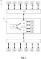
FIG. 1 is a diagram illustrating an example of abus emulator device 102 provided in atransportation device 100. As illustrated, thetransportation device 100 includes one or more mission critical systems ordevices 104A-F. In some non-limiting examples, mission critical systems or devices 104 may include, but are not limited to, the engine, brakes, accelerator, fuel injector, etc. In other examples, the mission critical systems or devices 104 may be different devices or systems, and the listed mission critical devices or systems or the characterization of devices or systems as "mission critical" should not be considered limiting on the current disclosure. The number of mission critical devices 104 should not be considered limiting on the current disclosure. Thetransportation device 100 may also include one or more peripheral systems ordevices 106A-F. In some non-limiting examples, peripheral devices may include, but are not limited to, navigation systems, radio, USB connectors, OBD connectors, entertainment systems, alarm systems, etc. In other examples, the peripheral systems or devices 106 may be different devices or systems, and the listed peripheral devices or systems or the characterization of devices or systems as "peripheral" should not be considered limiting on the current disclosure. The number of peripheral devices 106 should not be considered limiting on the current disclosure. The missioncritical devices 104A-F are connected into amain bus system 108 such that a normal exchange of data and information among the mission critical devices 104 is possible. In certain examples, theperipheral devices 106A-F are connected to thebus emulator device 102 such that they have read access to the information of the main bus system 108 (from the mission critical devices) but cannot modify the information. In some examples, the peripheral devices 106 are not physically connected into themain bus system 108. - The
bus emulator device 102 includes a firstindependent computer 110, a secondindependent computer 112, and the independent physical memory orinformation interface 114. While a singlebus emulator device 102 is illustrated, it will be appreciated that any number ofdevices 102 could be utilized. In some cases, each mission critical device 104 may have a dedicated emulator, although it need not in other examples. In various examples, thecomputer 110, thecomputer 112, and theinformation interface 114 run on the same tact generator, although they need not in other examples. - The first
independent computer 110 may be associated and in communication withBoot ROM 116 and amemory subsystem 118. Similarly, the secondindependent computer 112 may be associated and in communication withBoot ROM 120 and amemory subsystem 122. Theindependent computers - The
information interface 114 andmemory subsystems information interface 114 is shared memory where the firstindependent computer 110 has at least write capabilities (and optionally has read capabilities) and the secondindependent computer 112 only has read capabilities. In this example, theinformation interface 114 may always include the information from the hot bus system 108 (via the first independent computer 110) so that the secondindependent computer 112 can read the information to emulate thecold bus system 124. In other examples, theinformation interface 114 may be a memory that is only controlled by the secondindependent computer 112, and the secondindependent computer 112 may use it to directly emulate thecold bus system 124. In these examples, the secondindependent computer 112 may get the information by push from the firstindependent computer 110 or upon request. In further examples, the firstindependent computer 110 and the secondindependent computer 112 may each include at least one additional memory. In these examples, the firstindependent computer 110 may build up the information on theinformation interface 114, the secondindependent computer 112 may copy the information from theinformation interface 114 to its additional memory, and the secondindependent computer 112 may then allow peripheral devices to read and/or modify the content on the additional memory. - The first
independent computer 110, the secondindependent computer 112, and theinformation interface 114 are arranged and connected such that the secondindependent computer 112 can read current and past status information provided by or on the firstindependent computer 110 but cannot modify such information. -
FIG. 1 illustrates one configuration of the firstindependent computer 110, the secondindependent computer 112, and theinformation interface 114 where the secondindependent computer 112 can read current and past status information provided by or on the firstindependent computer 110 but cannot modify such information. As illustrated inFIG. 1 , in some examples, the firstindependent computer 110 has write access to theinformation interface 114 but not read access. In other examples, and as discussed in detail below, the firstindependent computer 110 has full access to the information interface 114 (e.g., read, write, delete, modify, etc.). The secondindependent computer 112 has read access to theinformation interface 114 but not write access. In other words, theinformation interface 114 is a one-way memory for data exchange between themain bus system 108 and an emulatedbus system 124. In some examples, the secondindependent computer 112 may read theinformation interface 114 upon a request and/or automatically (e.g., as a push). - Through the particular configuration of the bus emulator device 102 (i.e., the second
independent computer 112 can read current and past status information provided by or on the firstindependent computer 110 but cannot modify such information), the firstindependent computer 110 writes all needed information and data from the missioncritical devices 104A-F into theinformation interface 114. The secondindependent computer 112 reads the information and data from theinformation interface 114 and uses the data and information to emulate themain bus system 108 in the emulatedbus system 124. As illustrated, the emulatedbus system 124 may not have a physical (or direct) connection into themain bus system 108. In other words, the emulatedbus system 124 is only able to indirectly access information and data from themain bus system 108 via thebus emulator device 102. - In various examples, the emulated
bus system 124 may look the same or substantially the same as the main bus system 108 (although it need not be), meaning that the emulatedbus system 124 can simulate each of the missioncritical devices 104A-F. Theperipheral devices 106A-F may physically connect into the emulatedbus system 124, but theperipheral devices 106A-F do not have a physical connection to themain bus system 108. In other words, because the secondindependent computer 112 can only read theinformation interface 114, the emulated bus system 124 (and systems or devices connected to the emulated bus system 124) cannot manipulate the main bus system 108 (and systems or devices connected to the main bus system 108). In certain examples, providing the firstindependent computer 110 such that can only write into the information interface may provide an additional layer of security between the two computers. However, in other examples and as discussed in detail below, the firstindependent computer 110 may have full access to the information interface. -
FIG. 2 illustrates a non-limiting example of a possible software or firmware architecture on the emulated bus side. This software may be installed in theBoot ROM 120 or other computer readable medium associated with the secondindependent computer 112. The software architecture can be programmed in various suitable programming languages as desired. - With the
bus emulator device 102, theperipheral devices 106A-F may not realize that there is no physical or direct connection to the missioncritical devices 104A-F. This configuration may make it possible to install the bus emulator device in existing environments while maintaining compatibility. Such a configuration allows theperipheral devices 106A-F to still use the information from the missioncritical devices 104A-F without being able to manipulate the missioncritical devices 104A-F. As a non-limiting example, an OBD connector (a peripheral device) may connect with the emulatedbus system 124 to perform various diagnostics on the vehicle, but the OBD connector cannot be used to manipulate the mission critical devices 104. Updating of all peripheral devices is still possible with thebus emulator device 102. It will be appreciated that through thebus emulator device 102, the emulatedbus system 124 combines physical systems or devices (i.e., the peripheral devices 106) and virtual or emulated systems or devices (i.e., the simulated mission critical devices from reading the information interface 114). - Referring to
FIG. 3 , in some examples, thebus emulator device 102 optionally includes a second shared memory space 126 (or second information interface). Optionally, the second sharedmemory space 126 may allow for the write back of selected registers into themain bus system 108. Such selected registers may be predefined and controlled to limit the manipulation of thehot bus system 108 and the mission critical devices 104. -
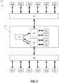
FIG. 4 illustrates another configuration of the firstindependent computer 110, the secondindependent computer 112, and theinformation interface 114 where the secondindependent computer 112 can read current and past status information provided by or on the firstindependent computer 110 but cannot modify such information. Compared to the configuration illustrated inFIG. 1 , in the configuration ofFIG. 4 , the firstindependent computer 110 has full access to the information interface 114 (e.g., read, write, delete, modify, etc.). In this example, theinformation interface 114 is a shared memory where the firstindependent computer 110 has read and write capabilities, and the secondindependent computer 112 only has read capabilities. In this example, theinformation interface 114 may always include the information from thehot bus system 108. -
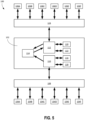
FIG. 5 illustrates another configuration of the firstindependent computer 110, the secondindependent computer 112, and theinformation interface 114 where the secondindependent computer 112 can read current and past status information provided by or on the firstindependent computer 110 but cannot modify such information to control thehot bus system 108. In this example, and compared to the configuration illustrated inFIG. 1 , the firstindependent computer 110 only has write access, and the secondindependent computer 112 has both read and write access. In this example, theinformation interface 114 is controlled by the secondindependent computer 112, and the second independent computer can use theinformation interface 114 to directly emulate thecold bus 124. In this example, because the firstindependent computer 110 only has write access, any modifications to the memory made by the secondindependent computer 112 cannot be used to control themain bus system 108. In this example, theinformation interface 114 may or may not always include current or past information of thehot bus system 108. -
FIG. 6 illustrates another configuration of the firstindependent computer 110, the secondindependent computer 112, and theinformation interface 114 where the secondindependent computer 112 can read current and past status information provided by or on the firstindependent computer 110 but cannot modify such information to control thehot bus system 108. In this example, and compared to the configuration illustrated inFIG. 1 , the secondindependent computer 112 has anadditional memory 119. Theadditional memory 119 may be the same type of memory as theinformation interface 114 or a different type of memory as desired. The firstindependent computer 110 may similarly have an additional memory, although it need not in other examples. In the example ofFIG. 6 , although the firstindependent computer 110 is illustrated with only write access to theinformation interface 114, in other examples the firstindependent computer 110 may have full access to theinformation interface 114. In the example ofFIG. 6 , the firstindependent computer 110 builds up the information about thehot bus system 108 on at least theinformation interface 114. The secondindependent computer 112 copies the information from theinformation interface 114 to theadditional memory 119. The peripheral devices 106 may read and/or modify the information on theadditional memory 119 as desired. - The foregoing is provided for purposes of illustrating, explaining, and describing embodiments of the present invention. Further modifications and adaptations to these embodiments will be apparent to those skilled in the art. Different arrangements of the components depicted in the drawings or described above, as well as components and steps not shown or described are possible. Similarly, some features and sub-combinations are useful and may be employed without reference to other features and sub-combinations. Embodiments of the invention have been described for illustrative and not restrictive purposes, and alternative embodiments will become apparent to readers of this patent. Accordingly, the present invention is not limited to the embodiments described above or depicted in the drawings. The invention is defined by the appended claims.
Claims (7)
- A bus emulator device (102) comprising:a first computer (110);a second computer (112); andan information interface (114),wherein the first computer is configured to connect to a main bus system (108) comprising at least one mission critical device (104) and write information and data from the at least one mission critical device into the information interface, and the second computer is configured to read the information and data from the information interface and use the data and information to emulate the main bus system in an emulated bus system (124)wherein either i) the first computer comprises at least write access into the information interface, and the second computer comprises read-only access into the information interface, orii) the first computer comprises write-only access into the information interface and the second computer comprises at least read access into the information interface.
- The bus emulator device (102) of claim 1, wherein the second computer (112) comprises read-only access into the information interface (114) and the first computer (110) comprises at least read access and write access into the information interface.
- The bus emulator device of claim 1, wherein the first computer (110) comprises write-only access into the information interface (114) and the second computer comprises at least read and write access into the information interface.
- The bus emulator device (102) of any of claims 1-3, wherein the emulated bus system comprises at least one peripheral system connectable to an external network.
- The bus emulator device (102) of any one of claims 1 to 3, further comprising a tact generator, and wherein the first computer (110), the second computer (112), and the information interface (114) run on the tact generator.
- The bus emulator device (102) of any one of claims 1 to 3 or 5, further comprising:an additional memory (119),wherein the first computer (110) has no access to the additional memory, andwherein the second computer (112) comprises read access and write access into the additional memory.
- A system (100) comprising:a first bus system (108);a second bus system (124); andthe bus emulator device (102) of any preceding claim connected to the first bus system and the second bus system, wherein the bus emulator device physically isolates the first bus system from the second bus system, and wherein the first bus system is a main bus system and the second bus system is an emulated bus system.
Applications Claiming Priority (2)
| Application Number | Priority Date | Filing Date | Title |
|---|---|---|---|
| US201962903711P | 2019-09-20 | 2019-09-20 | |
| PCT/IB2020/058586 WO2021053517A1 (en) | 2019-09-20 | 2020-09-16 | Automotive, naval, and aircraft bus-emulator |
Publications (3)
| Publication Number | Publication Date |
|---|---|
| EP4032001A1 EP4032001A1 (en) | 2022-07-27 |
| EP4032001C0 EP4032001C0 (en) | 2024-10-30 |
| EP4032001B1 true EP4032001B1 (en) | 2024-10-30 |
Family
ID=72717892
Family Applications (1)
| Application Number | Title | Priority Date | Filing Date |
|---|---|---|---|
| EP20785839.0A Active EP4032001B1 (en) | 2019-09-20 | 2020-09-16 | Automotive, naval, and aircraft bus-emulator |
Country Status (5)
| Country | Link |
|---|---|
| US (1) | US11956096B2 (en) |
| EP (1) | EP4032001B1 (en) |
| CA (1) | CA3151869A1 (en) |
| ES (1) | ES3006464T3 (en) |
| WO (1) | WO2021053517A1 (en) |
Families Citing this family (2)
| Publication number | Priority date | Publication date | Assignee | Title |
|---|---|---|---|---|
| ES3006464T3 (en) | 2019-09-20 | 2025-03-18 | Rockpatech Ag | Automotive, naval, and aircraft bus-emulator |
| US12497194B2 (en) | 2023-09-29 | 2025-12-16 | General Electric Company | Aircraft monitoring system |
Family Cites Families (10)
| Publication number | Priority date | Publication date | Assignee | Title |
|---|---|---|---|---|
| CN1564997A (en) * | 2001-09-07 | 2005-01-12 | 米-茵有限公司 | Operating device |
| DE10241545A1 (en) * | 2002-09-05 | 2004-03-25 | Gkss-Forschungszentrum Geesthacht Gmbh | Device for converting a continuous flow of liquid into a flow of liquid droplets |
| US8419608B2 (en) * | 2007-09-26 | 2013-04-16 | Mega-Wave-Gmbh | Apparatus for producing fields for treatment of bodily parts of living organisms for healing purposes |
| EP3651437B1 (en) * | 2012-03-29 | 2021-02-24 | Arilou Information Security Technologies Ltd. | Protecting a vehicle electronic system |
| US9257240B2 (en) * | 2012-06-26 | 2016-02-09 | Samsung Electronics Co., Ltd. | Key assembly and electronic device having the same |
| JP2015170282A (en) * | 2014-03-10 | 2015-09-28 | トヨタ自動車株式会社 | Vehicle control device |
| US10666615B2 (en) * | 2015-08-03 | 2020-05-26 | Sectigo, Inc. | Method for detecting, blocking and reporting cyber-attacks against automotive electronic control units |
| KR101969264B1 (en) * | 2018-08-27 | 2019-04-16 | 주식회사 엔디소프트 | Method for automatically inserting keywords for searching a certain of contents with special identifier code |
| US20200145338A1 (en) * | 2018-11-04 | 2020-05-07 | Terafence Ltd. | Application specific gateway device |
| ES3006464T3 (en) | 2019-09-20 | 2025-03-18 | Rockpatech Ag | Automotive, naval, and aircraft bus-emulator |
-
2020
- 2020-09-16 ES ES20785839T patent/ES3006464T3/en active Active
- 2020-09-16 EP EP20785839.0A patent/EP4032001B1/en active Active
- 2020-09-16 CA CA3151869A patent/CA3151869A1/en active Pending
- 2020-09-16 US US17/762,076 patent/US11956096B2/en active Active
- 2020-09-16 WO PCT/IB2020/058586 patent/WO2021053517A1/en not_active Ceased
Also Published As
| Publication number | Publication date |
|---|---|
| CA3151869A1 (en) | 2021-03-25 |
| EP4032001C0 (en) | 2024-10-30 |
| US11956096B2 (en) | 2024-04-09 |
| WO2021053517A1 (en) | 2021-03-25 |
| EP4032001A1 (en) | 2022-07-27 |
| US20220393905A1 (en) | 2022-12-08 |
| ES3006464T3 (en) | 2025-03-18 |
Similar Documents
| Publication | Publication Date | Title |
|---|---|---|
| JP7685184B2 (en) | Specially programmed computing system having associated devices configured to implement secure lockdown and method of use thereof - Patents.com | |
| CN105871830B (en) | Firewall of a car information system | |
| Macher et al. | Integrated safety and security development in the automotive domain | |
| EP3393088B1 (en) | System and method of monitoring data traffic on a mil-std-1553 data bus | |
| EP4032001B1 (en) | Automotive, naval, and aircraft bus-emulator | |
| US20220171611A1 (en) | Electronic control unit, software update method, software update program product and electronic control system | |
| CN114802052A (en) | Trusted environment self-learning method and system for vehicle-mounted network intrusion detection system | |
| JP2013009370A (en) | Secure data store for vehicle networks | |
| WO2019004638A1 (en) | Method and system for setting electronic controller security function | |
| CN112537316A (en) | Method for at least partially automatically guiding a motor vehicle | |
| US10958472B2 (en) | Direct access to bus signals in a motor vehicle | |
| US20220308858A1 (en) | Vehicle program update management system, reprogramming terminal, and vehicle program update management method | |
| CN213186571U (en) | ECU security upgrading system applied to vehicle-mounted network | |
| US20260006029A1 (en) | Management of vehicle network access | |
| US10581632B2 (en) | Data transfer filter | |
| WO2025045019A1 (en) | Control method and apparatus | |
| US20250053636A1 (en) | Computer system protection | |
| CN119226152A (en) | Security strategy construction method, device, equipment and vehicle for vehicle system | |
| CN120226005A (en) | Identifying external interventions in a computer system with zoning for a device, in particular for a vehicle | |
| Siddiqui et al. | Embedded Policing and Policy Enforcement based Security in the era of Digital-Physical Convergence for Next-Generation Vehicular Electronics | |
| CN120872389A (en) | Vehicle-mounted application program updating method and system and vehicle |
Legal Events
| Date | Code | Title | Description |
|---|---|---|---|
| STAA | Information on the status of an ep patent application or granted ep patent |
Free format text: STATUS: UNKNOWN |
|
| STAA | Information on the status of an ep patent application or granted ep patent |
Free format text: STATUS: THE INTERNATIONAL PUBLICATION HAS BEEN MADE |
|
| PUAI | Public reference made under article 153(3) epc to a published international application that has entered the european phase |
Free format text: ORIGINAL CODE: 0009012 |
|
| STAA | Information on the status of an ep patent application or granted ep patent |
Free format text: STATUS: REQUEST FOR EXAMINATION WAS MADE |
|
| 17P | Request for examination filed |
Effective date: 20220419 |
|
| AK | Designated contracting states |
Kind code of ref document: A1 Designated state(s): AL AT BE BG CH CY CZ DE DK EE ES FI FR GB GR HR HU IE IS IT LI LT LU LV MC MK MT NL NO PL PT RO RS SE SI SK SM TR |
|
| DAV | Request for validation of the european patent (deleted) | ||
| DAX | Request for extension of the european patent (deleted) | ||
| RAP1 | Party data changed (applicant data changed or rights of an application transferred) |
Owner name: ROCKPATECH AG |
|
| RIN1 | Information on inventor provided before grant (corrected) |
Inventor name: KUSTER, MARTIN |
|
| GRAP | Despatch of communication of intention to grant a patent |
Free format text: ORIGINAL CODE: EPIDOSNIGR1 |
|
| STAA | Information on the status of an ep patent application or granted ep patent |
Free format text: STATUS: GRANT OF PATENT IS INTENDED |
|
| INTG | Intention to grant announced |
Effective date: 20240524 |
|
| GRAS | Grant fee paid |
Free format text: ORIGINAL CODE: EPIDOSNIGR3 |
|
| GRAA | (expected) grant |
Free format text: ORIGINAL CODE: 0009210 |
|
| STAA | Information on the status of an ep patent application or granted ep patent |
Free format text: STATUS: THE PATENT HAS BEEN GRANTED |
|
| AK | Designated contracting states |
Kind code of ref document: B1 Designated state(s): AL AT BE BG CH CY CZ DE DK EE ES FI FR GB GR HR HU IE IS IT LI LT LU LV MC MK MT NL NO PL PT RO RS SE SI SK SM TR |
|
| REG | Reference to a national code |
Ref country code: GB Ref legal event code: FG4D |
|
| REG | Reference to a national code |
Ref country code: CH Ref legal event code: EP |
|
| REG | Reference to a national code |
Ref country code: DE Ref legal event code: R096 Ref document number: 602020040402 Country of ref document: DE |
|
| REG | Reference to a national code |
Ref country code: IE Ref legal event code: FG4D |
|
| U01 | Request for unitary effect filed |
Effective date: 20241127 |
|
| U07 | Unitary effect registered |
Designated state(s): AT BE BG DE DK EE FI FR IT LT LU LV MT NL PT RO SE SI Effective date: 20241203 |
|
| REG | Reference to a national code |
Ref country code: ES Ref legal event code: FG2A Ref document number: 3006464 Country of ref document: ES Kind code of ref document: T3 Effective date: 20250318 |
|
| PG25 | Lapsed in a contracting state [announced via postgrant information from national office to epo] |
Ref country code: IS Free format text: LAPSE BECAUSE OF FAILURE TO SUBMIT A TRANSLATION OF THE DESCRIPTION OR TO PAY THE FEE WITHIN THE PRESCRIBED TIME-LIMIT Effective date: 20250228 Ref country code: HR Free format text: LAPSE BECAUSE OF FAILURE TO SUBMIT A TRANSLATION OF THE DESCRIPTION OR TO PAY THE FEE WITHIN THE PRESCRIBED TIME-LIMIT Effective date: 20241030 |
|
| PG25 | Lapsed in a contracting state [announced via postgrant information from national office to epo] |
Ref country code: NO Free format text: LAPSE BECAUSE OF FAILURE TO SUBMIT A TRANSLATION OF THE DESCRIPTION OR TO PAY THE FEE WITHIN THE PRESCRIBED TIME-LIMIT Effective date: 20250130 |
|
| PG25 | Lapsed in a contracting state [announced via postgrant information from national office to epo] |
Ref country code: GR Free format text: LAPSE BECAUSE OF FAILURE TO SUBMIT A TRANSLATION OF THE DESCRIPTION OR TO PAY THE FEE WITHIN THE PRESCRIBED TIME-LIMIT Effective date: 20250131 |
|
| PG25 | Lapsed in a contracting state [announced via postgrant information from national office to epo] |
Ref country code: PL Free format text: LAPSE BECAUSE OF FAILURE TO SUBMIT A TRANSLATION OF THE DESCRIPTION OR TO PAY THE FEE WITHIN THE PRESCRIBED TIME-LIMIT Effective date: 20241030 |
|
| PG25 | Lapsed in a contracting state [announced via postgrant information from national office to epo] |
Ref country code: RS Free format text: LAPSE BECAUSE OF FAILURE TO SUBMIT A TRANSLATION OF THE DESCRIPTION OR TO PAY THE FEE WITHIN THE PRESCRIBED TIME-LIMIT Effective date: 20250130 |
|
| PG25 | Lapsed in a contracting state [announced via postgrant information from national office to epo] |
Ref country code: SM Free format text: LAPSE BECAUSE OF FAILURE TO SUBMIT A TRANSLATION OF THE DESCRIPTION OR TO PAY THE FEE WITHIN THE PRESCRIBED TIME-LIMIT Effective date: 20241030 |
|
| PG25 | Lapsed in a contracting state [announced via postgrant information from national office to epo] |
Ref country code: SK Free format text: LAPSE BECAUSE OF FAILURE TO SUBMIT A TRANSLATION OF THE DESCRIPTION OR TO PAY THE FEE WITHIN THE PRESCRIBED TIME-LIMIT Effective date: 20241030 |
|
| PG25 | Lapsed in a contracting state [announced via postgrant information from national office to epo] |
Ref country code: CZ Free format text: LAPSE BECAUSE OF FAILURE TO SUBMIT A TRANSLATION OF THE DESCRIPTION OR TO PAY THE FEE WITHIN THE PRESCRIBED TIME-LIMIT Effective date: 20241030 |
|
| PLBE | No opposition filed within time limit |
Free format text: ORIGINAL CODE: 0009261 |
|
| STAA | Information on the status of an ep patent application or granted ep patent |
Free format text: STATUS: NO OPPOSITION FILED WITHIN TIME LIMIT |
|
| 26N | No opposition filed |
Effective date: 20250731 |
|
| REG | Reference to a national code |
Ref country code: CH Ref legal event code: U11 Free format text: ST27 STATUS EVENT CODE: U-0-0-U10-U11 (AS PROVIDED BY THE NATIONAL OFFICE) Effective date: 20251027 |
|
| U21 | Renewal fee for the european patent with unitary effect paid with additional fee |
Year of fee payment: 6 Effective date: 20251001 |
|
| PGFP | Annual fee paid to national office [announced via postgrant information from national office to epo] |
Ref country code: GB Payment date: 20251024 Year of fee payment: 6 |
|
| PGFP | Annual fee paid to national office [announced via postgrant information from national office to epo] |
Ref country code: CH Payment date: 20251027 Year of fee payment: 6 |
|
| PGFP | Annual fee paid to national office [announced via postgrant information from national office to epo] |
Ref country code: ES Payment date: 20251020 Year of fee payment: 6 |