EP4031479B1 - Method and machine for filling a container to a desired liquid level - Google Patents
Method and machine for filling a container to a desired liquid level Download PDFInfo
- Publication number
- EP4031479B1 EP4031479B1 EP20820483.4A EP20820483A EP4031479B1 EP 4031479 B1 EP4031479 B1 EP 4031479B1 EP 20820483 A EP20820483 A EP 20820483A EP 4031479 B1 EP4031479 B1 EP 4031479B1
- Authority
- EP
- European Patent Office
- Prior art keywords
- filling
- container
- filling tube
- liquid
- tube
- Prior art date
- Legal status (The legal status is an assumption and is not a legal conclusion. Google has not performed a legal analysis and makes no representation as to the accuracy of the status listed.)
- Active
Links
- 239000007788 liquid Substances 0.000 title claims description 107
- 238000000034 method Methods 0.000 title claims description 26
- 238000004891 communication Methods 0.000 claims description 24
- 238000007789 sealing Methods 0.000 claims description 18
- 238000013519 translation Methods 0.000 claims description 11
- 230000006641 stabilisation Effects 0.000 claims description 2
- 238000006073 displacement reaction Methods 0.000 claims 2
- 238000011105 stabilization Methods 0.000 claims 1
- 210000003739 neck Anatomy 0.000 description 19
- IJGRMHOSHXDMSA-UHFFFAOYSA-N Atomic nitrogen Chemical compound N#N IJGRMHOSHXDMSA-UHFFFAOYSA-N 0.000 description 10
- 235000014101 wine Nutrition 0.000 description 6
- 229910052757 nitrogen Inorganic materials 0.000 description 5
- QVGXLLKOCUKJST-UHFFFAOYSA-N atomic oxygen Chemical compound [O] QVGXLLKOCUKJST-UHFFFAOYSA-N 0.000 description 4
- 238000005429 filling process Methods 0.000 description 4
- 230000005484 gravity Effects 0.000 description 4
- 238000002347 injection Methods 0.000 description 4
- 239000007924 injection Substances 0.000 description 4
- 239000001301 oxygen Substances 0.000 description 4
- 229910052760 oxygen Inorganic materials 0.000 description 4
- 230000001105 regulatory effect Effects 0.000 description 4
- 238000010521 absorption reaction Methods 0.000 description 3
- 239000006260 foam Substances 0.000 description 2
- 239000011521 glass Substances 0.000 description 2
- 230000003647 oxidation Effects 0.000 description 2
- 238000007254 oxidation reaction Methods 0.000 description 2
- 101100536354 Drosophila melanogaster tant gene Proteins 0.000 description 1
- 238000005273 aeration Methods 0.000 description 1
- 230000001476 alcoholic effect Effects 0.000 description 1
- 238000013459 approach Methods 0.000 description 1
- 235000019568 aromas Nutrition 0.000 description 1
- 230000000903 blocking effect Effects 0.000 description 1
- 235000009508 confectionery Nutrition 0.000 description 1
- 230000007423 decrease Effects 0.000 description 1
- 238000002474 experimental method Methods 0.000 description 1
- 239000011261 inert gas Substances 0.000 description 1
- 238000007726 management method Methods 0.000 description 1
- 239000002184 metal Substances 0.000 description 1
- 238000012986 modification Methods 0.000 description 1
- 230000004048 modification Effects 0.000 description 1
- 239000002245 particle Substances 0.000 description 1
- 230000002093 peripheral effect Effects 0.000 description 1
- 230000000284 resting effect Effects 0.000 description 1
- 239000000243 solution Substances 0.000 description 1
Images


Classifications
-
- B—PERFORMING OPERATIONS; TRANSPORTING
- B67—OPENING, CLOSING OR CLEANING BOTTLES, JARS OR SIMILAR CONTAINERS; LIQUID HANDLING
- B67C—CLEANING, FILLING WITH LIQUIDS OR SEMILIQUIDS, OR EMPTYING, OF BOTTLES, JARS, CANS, CASKS, BARRELS, OR SIMILAR CONTAINERS, NOT OTHERWISE PROVIDED FOR; FUNNELS
- B67C3/00—Bottling liquids or semiliquids; Filling jars or cans with liquids or semiliquids using bottling or like apparatus; Filling casks or barrels with liquids or semiliquids
- B67C3/02—Bottling liquids or semiliquids; Filling jars or cans with liquids or semiliquids using bottling or like apparatus
- B67C3/22—Details
- B67C3/28—Flow-control devices, e.g. using valves
- B67C3/286—Flow-control devices, e.g. using valves related to flow rate control, i.e. controlling slow and fast filling phases
-
- B—PERFORMING OPERATIONS; TRANSPORTING
- B67—OPENING, CLOSING OR CLEANING BOTTLES, JARS OR SIMILAR CONTAINERS; LIQUID HANDLING
- B67C—CLEANING, FILLING WITH LIQUIDS OR SEMILIQUIDS, OR EMPTYING, OF BOTTLES, JARS, CANS, CASKS, BARRELS, OR SIMILAR CONTAINERS, NOT OTHERWISE PROVIDED FOR; FUNNELS
- B67C3/00—Bottling liquids or semiliquids; Filling jars or cans with liquids or semiliquids using bottling or like apparatus; Filling casks or barrels with liquids or semiliquids
- B67C3/02—Bottling liquids or semiliquids; Filling jars or cans with liquids or semiliquids using bottling or like apparatus
- B67C3/06—Bottling liquids or semiliquids; Filling jars or cans with liquids or semiliquids using bottling or like apparatus using counterpressure, i.e. filling while the container is under pressure
- B67C3/12—Pressure-control devices
-
- B—PERFORMING OPERATIONS; TRANSPORTING
- B67—OPENING, CLOSING OR CLEANING BOTTLES, JARS OR SIMILAR CONTAINERS; LIQUID HANDLING
- B67C—CLEANING, FILLING WITH LIQUIDS OR SEMILIQUIDS, OR EMPTYING, OF BOTTLES, JARS, CANS, CASKS, BARRELS, OR SIMILAR CONTAINERS, NOT OTHERWISE PROVIDED FOR; FUNNELS
- B67C3/00—Bottling liquids or semiliquids; Filling jars or cans with liquids or semiliquids using bottling or like apparatus; Filling casks or barrels with liquids or semiliquids
- B67C3/02—Bottling liquids or semiliquids; Filling jars or cans with liquids or semiliquids using bottling or like apparatus
- B67C3/22—Details
- B67C3/26—Filling-heads; Means for engaging filling-heads with bottle necks
- B67C3/2614—Filling-heads; Means for engaging filling-heads with bottle necks specially adapted for counter-pressure filling
- B67C3/2625—Filling-heads; Means for engaging filling-heads with bottle necks specially adapted for counter-pressure filling the liquid valve being opened automatically when a given counter-pressure is obtained in the container to be filled
- B67C3/2628—Filling-heads; Means for engaging filling-heads with bottle necks specially adapted for counter-pressure filling the liquid valve being opened automatically when a given counter-pressure is obtained in the container to be filled and the filling operation stopping when the liquid rises to a level at which it closes a vent opening
-
- B—PERFORMING OPERATIONS; TRANSPORTING
- B67—OPENING, CLOSING OR CLEANING BOTTLES, JARS OR SIMILAR CONTAINERS; LIQUID HANDLING
- B67C—CLEANING, FILLING WITH LIQUIDS OR SEMILIQUIDS, OR EMPTYING, OF BOTTLES, JARS, CANS, CASKS, BARRELS, OR SIMILAR CONTAINERS, NOT OTHERWISE PROVIDED FOR; FUNNELS
- B67C3/00—Bottling liquids or semiliquids; Filling jars or cans with liquids or semiliquids using bottling or like apparatus; Filling casks or barrels with liquids or semiliquids
- B67C3/02—Bottling liquids or semiliquids; Filling jars or cans with liquids or semiliquids using bottling or like apparatus
- B67C3/22—Details
- B67C3/26—Filling-heads; Means for engaging filling-heads with bottle necks
- B67C2003/2651—The liquid valve being carried by the vent tube
- B67C2003/2654—The liquid valve being carried by the vent tube specially adapted for bottom filling, e.g. the liquid valve being located at the lowest part of the vent tube
-
- B—PERFORMING OPERATIONS; TRANSPORTING
- B67—OPENING, CLOSING OR CLEANING BOTTLES, JARS OR SIMILAR CONTAINERS; LIQUID HANDLING
- B67C—CLEANING, FILLING WITH LIQUIDS OR SEMILIQUIDS, OR EMPTYING, OF BOTTLES, JARS, CANS, CASKS, BARRELS, OR SIMILAR CONTAINERS, NOT OTHERWISE PROVIDED FOR; FUNNELS
- B67C3/00—Bottling liquids or semiliquids; Filling jars or cans with liquids or semiliquids using bottling or like apparatus; Filling casks or barrels with liquids or semiliquids
- B67C3/02—Bottling liquids or semiliquids; Filling jars or cans with liquids or semiliquids using bottling or like apparatus
- B67C3/22—Details
- B67C3/26—Filling-heads; Means for engaging filling-heads with bottle necks
- B67C2003/2671—Means for preventing foaming of the liquid
Definitions
- the object of the invention relates to the technical field of filling containers of any type known per se, such as glass or plastic, using a filling liquid of any kind.
- the object of the invention finds a particularly advantageous application for filling containers of all types of shapes and formats with products sensitive to oxidation such as wines.
- a filling machine comprising a storage tank for a filling liquid.
- This storage tank is connected to one and generally to a series of filling heads to each of which the containers are successively brought and then removed after filling.
- Each filling head has a filling tube passing through a support seat for the neck of the container.
- the tube is intended to penetrate inside the container and internally comprises a discharge cannula making it possible to recover the air expelled from the interior of the container by the filling liquid.
- Vacuum is maintained inside the storage tank to ensure liquid flow from the end of the filling tube.
- the liquid passes through the discharge cannula to the tank or a storage container.
- the liquid level inside the container is determined by the lower end of the filling tube.
- filling containers using vacuum is likely to affect the quality of the filling liquid due to aeration of the liquid.
- the vacuum modifies the gaseous balances of certain liquids and leads to a loss of aromas.
- the quality of the liquid is also affected by the recirculation of the liquid which occurs in the presence of the container on the receiving seat and even in the absence of the container, with a lower recirculation flow rate.
- the filling operation turns out in practice, particularly at the end of the filling operation, to be relatively long given the creation of bubbles or foam making it difficult to level the liquid.
- the document FROM 11 85 497 describes a technique for filling containers using a filling liquid stored in a pressure-regulated tank and delivered using at least one filling head comprising a filling tube passing through a support seat for the container and fitted with a main shutter to authorize or interrupt the passage of the filling liquid.
- the filling tube internally comprises a discharge cannula and externally delimits with the support seat, a communication passage with a circuit for a regulated leak for the container equipped with a shutter controlled in opening and closing.
- the discharge cannula is connected by shutters controlled either to a regulated leak circuit for the cannula, or to a communication circuit with the tank allowing the filling of the container in gravity mode.
- the filling tube shutter is controlled by a controlled actuator.
- the neck of the container is then sealed by means of a filling tap which coaxially includes the aforementioned nitrogen injection nozzle.
- a vacuum is then created inside the container and the wine is then poured into the container which flows over the surfaces of the internal walls of the container, from its neck to its bottom.
- the correct fill level is obtained by sucking the excess wine from the container.
- This classic process above has been described for example in the patent application WO 2016/030786 in which the filling of the container is carried out using a sliding tube inside the container with the liquid exiting the tube at the bottom of the bottle and then the liquid level rises to the neck, thereby reducing turbulence which classically promote the absorption of oxygen.
- Such a process leads to delicate implementation for managing the injection of nitrogen.
- this process does not guarantee a precise level for the final level of liquid inside the container due to the management of the regularity of the vacuum and the suction time.
- FR 2 213 902 A1 discloses a method and a machine for filling containers not using nitrogen injection but using a filling liquid stored in a tank and delivered using at least one filling head filling comprising a spout tip provided with a support seat for a neck of a container, the spout tip being crossed by a filling tube connected to the tank and delimiting with the spout tip, at least one part of an air return circuit, the filling tube delimiting an outlet passage for the liquid open or closed using a closing device.
- the present invention therefore aims to remedy the drawbacks of the state of the art by proposing a new filling technique not requiring the injection of nitrogen while limiting the absorption of oxygen by the liquid, this process allowing containers to be filled to a desired and reproducible level.
- Another object of the invention aims to make it possible to fill containers of all shapes and sizes.
- the object of the invention relates to a machine I intended to fill, using a liquid 1, a container 2 to a determined level.
- the container 2 can be of any type, for example made of plastic, glass or even metal.
- a container 2 is a hollow object comprising a bottom 2a connected to a heel or jable from which rises a body 2b extending by a shoulder connected to a neck or neck 2c terminated by a ring 2d delimiting the mouth for filling or emptying the container.
- the liquid 1 can be of any nature such as, for example, alcoholic, sweet, carbonated, flavored, colored, with or without particles, etc.
- liquid 1 is a liquid sensitive to oxidation such as wine.
- the filling machine I comprises a storage tank 3 for the liquid 1, maintained at a regulating pressure by any appropriate means 4 such as for example by a pressure regulator.
- the tank 3 is maintained at a pressure corresponding to atmospheric pressure.
- the filling machine I also comprises at least one and generally several filling heads 6 adapted to fill by gravity, each a container 2 with the liquid 1 leaving the storage tank 3 located at a higher level per relative to the mounting level of the filling heads 6. After filling, each container 2 is evacuated and replaced by a new container for filling.
- the filling machine I comprises for this purpose, a container handling system 7 making it possible to bring each container 2 to a filling head 6 and to release each of the containers after their filling.
- This container handling system 7 can be produced in any appropriate manner.
- this handling system 7 comprises, for each filling head 6, a gripping clamp allowing the containers to be moved by their necks.
- the filling machine I is not described more precisely because it can take different shapes or configurations depending in particular on the number of filling heads 6. According to the description which follows, only the operation of a filling head 6 is described , but it is clear that the object of the invention can be applied to a machine comprising a series of filling heads, for example distributed along a line or at its periphery in order to produce the machine in the form of a carousel.
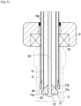
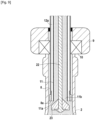
- Each filling head 6 has a spout tip 8 provided with a support seat 9 for the neck of the container.
- the nozzle tip 8 is made by a tube or a cannula whose section is adapted to be able to be introduced into the container 2 through its neck.
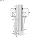
- This nozzle end 8 has a lower end 8a ( Fig. 2 ).
- the spout tip 8 is externally equipped with the support seat 9 which is provided with a support seal 10 for the container in the filling position.
- each container 2 is supported by its neck or more precisely by its ring surface 2d on the support seal 10 so as to ensure a seal between the spout end 8 and the neck 2c of the container.
- Each container 2 is thus moved by the handling system 7 to engage the neck around the spout tip 8 and come through its ring surface 2d, resting on the seal 10.
- each filled container 2 is evacuated by the handling system 7 which ensures the delivery of the next container to the filling head.
- the support seat 9 is mounted with the possibility of adjustment relative to the lower end 8a of the spout tip 8 to allow the level of the liquid in the container to be adjusted.
- the support seat 9 is slidably mounted on the nozzle end 8 with a locking system in a predetermined position of all types known per se.
- the nozzle tip 8 may include graduations to facilitate the positioning in a defined position of the support seat 9 relative to the lower end 8a of the nozzle end 8.
- Each spout end 8 is crossed by a filling tube 11 communicating with the storage tank 3 and mounted movable in vertical translation.
- the filling tube 11 passes through the spout tip 8 to delimit with the spout tip, a part 12a of an air return circuit 12 in communication with the interior of the container in order to place it at a value of pressure determined as a function of the filling cycle, as will be explained later in the description.
- the nozzle tip 8 and the filling tube 11 extend coaxially with each other, delimiting between them an annular chamber 12a forming part of the air return circuit 12 ( Fig. 2 ).
- a dynamic sealing system 13 is put in place between the upper part of the nozzle tip 8 and the sliding filling tube 11 in order to close the upper part of the annular chamber 12a.
- This air return circuit 12 also includes a connection pipe 12b with the annular chamber 12a and connected either to atmospheric pressure or to a pressure chamber 14 via a chamber shutter 15.
- the connection pipe 12b is connected via a tank shutter 16, to the sky 3a of the tank 3 whose pressure is maintained equal to atmospheric pressure.
- the air return circuit 12 is placed either at atmospheric pressure (via the tank shutter 16) or at a pressure value greater than atmospheric pressure (via the chamber shutter 15).
- a sealing system 17 ensures the closure of the air return circuit 12 when the filling tube 11 occupies a high position ( Fig. 3 ).
- Such a sealing system 17 can be produced in any appropriate manner. A preferred embodiment will be described later in the description.
- the filling tube 11 has a lower end 11a defining an outlet passage 11b for the liquid.
- the lower end 11a always extends below the support seat 9.
- the filling tube 11 extends thus projecting from the support seat 9 allowing the introduction of the filling tube 11 through its lower end 11a inside the container 2.
- the filling tube 11 is a rigid tube connected to the bottom of tank 3 using a flexible 11c.
- the filling tube 11 is movable in a vertical direction using a movement actuator 18 between a high position and a low position defined in relation to the depth of engagement of the filling tube inside the container.
- the upper position of the filling tube 11 corresponds to the position in a filling cycle, for which the filling tube 11 occupies the highest position.
- This high position can correspond to the leveling position for which the filling tube 11 is engaged inside the container at a depth corresponding to the level of the liquid to be reached inside the container.
- the distance between the support seat 9 and the lower end 11a of the filling tube thus corresponds to the final height of the liquid inside the container 2.
- the lower end 11a of the filling tube is located at the level of the lower end 8a of the spout tip 8 as illustrated in Fig. 2
- the high position of the filling tube 11 can also correspond, according to a preferred embodiment described in detail in the remainder of the description, to a position of the filling tube higher than the leveling position and for which the filling tube 11 closes the air return circuit 12.
- this high position called complete closure illustrated in Fig. 3 the sealing system 17 closes the air return circuit 12 between the lower end 11a of the filling tube and the lower end 8a of the spout tip 8.
- the lower position of the filling tube 11 corresponds to a positioning of the lower end 11a of the filling tube at the level of the bottom 2a of the container.
- the lower end 11a of the filling tube is not in contact with the bottom of the container but is close to the pitted bottom.
- the movement actuator 18 has a movement stroke making it possible to position the lower end 11a of the filling tube 11 between this high position and this low position.
- the actuator 18 is an electric cylinder but it is clear that this actuator can be produced in any suitable manner.
- This actuator 18 comprises an actuating rod 18a sliding in a body 18b and acting on a support 20 supporting the filling tube 11. As shown in the drawings, the upper end of the filling tube 11 is fixed on the support 20 .
- the outlet passage 11b of the filling tube 11 is opened or closed using a closing device 21 of all types.
- the shutter device 21 comprises a rod 22 mounted coaxially inside the filling tube 11.
- This rod 22 is equipped at its lower part with a shutter 23 suitable for opening or closing the outlet passage 11b of the filling tube depending on the position of the rod.
- the rod 22 is mounted movable in translation relative to the filling tube 11 using an actuator 25 which controls at least the blocking of the outlet passage 11b of the filling tube.
- This shutter actuator 25 moves the rod 22 so that the shutter 23 can open or close the outlet passage 11b of the filling tube.
- the rod 22 To move from the open position to the closed position of the outlet passage 11b, the rod 22 is moved upwards relative to the filling tube 11 so that the shutter 23 comes to cooperate with the lower end 11a in order to close its exit passage 11b. To move from the closed position to the open position of the outlet passage 11b, the rod 22 is moved downwards relative to the filling tube 11 so that the shutter 23 does not cooperate with the lower end 11a in order to open its exit passage 11b.
- the stroke of the rod 22 is adapted so that in the open position, the shutter 23 does not reduce the outlet passage 11b of the filling tube 11.
- the rod 22 is guided in sliding by the support 20 on which the shutter actuator 25 is advantageously mounted.
- the shutter actuator 25 is produced by an electric or pneumatic actuator.
- the rod 22 is part of the sealing system 17 which ensures the closure of the air return circuit 12 when the filling tube 11 occupies the high position known as complete closure ( Fig. 3 ) but which ensures the opening of the air return circuit 12 when the filling tube 11 is lowered relative to the spout tip 8 ( Fig. 2 ).
- the lower end of the rod 22 is provided with a seal 17a forming part of the sealing system 17 and extending radially beyond the filling tube 11 to cooperate with the lower end 8a of the nozzle tip 8 to ensure closure of the air return circuit 12.
- the shutter 23 and the seal 17a are made by a common seal carried by the lower end of the rod 22.
- This common seal 23, 17a has a shape frustoconical with its central part closing the filling tube 11 while its peripheral part closes the annular chamber 12a delimited between the filling tube 11 and the spout tip 8.
- This common seal 23, 17a is produced in any case suitable for carrying out the sealing functions described.
- the filling tube 11 is moved upwards relative to the spout tip 8 so that the sealing system 17 ensures closure of the lower part of the annular chamber 12a delimited between the nozzle tip 8 and the filling tube 11. In this closed position illustrated in Fig. 3 , the lower end 11a of the filling tube occupies a higher level compared to the lower end 8a of the spout tip 8.
- the filling machine I also includes a control circuit 28 connected to the chamber shutter 15, to the tank shutter 16, to the movement actuator 18 of the filling tube 11 and to the shutter actuator 25 allowing the opening or closing of the outlet passage of the tube filling 11.
- the control circuit 28 makes it possible to control the operation of the chamber shutter 15, the tank shutter 16, the movement actuator 18 of the filling tube 11 and the shutter actuator 25 to implement a filling process according to the invention.
- the control circuit 28 also controls the sealing system 17 which ensures the closure of the air return circuit 12. In the example illustrated, the sealing system 17 is controlled by the filling tube 11 whose movement is controlled by the movement actuator 18.
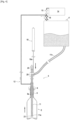
- FIG. 1 illustrates a filling head 6 in a post or pre-filling position in which the outlet passage 11b of the filling tube 11 is closed and the air return circuit 12 is also closed by the closing device 21.
- the tube filling 11 occupies the high position called complete closure also illustrated in Fig. 3 .
- the filling process consists of bringing the neck 2c of the container 2 to rest on the seat 9 of the filling head while engaging the nozzle tip 8 inside the container 2.
- the handling system 7 moves the container 2 to bring its ring surface 2d to rest on the seat 9.
- the method consists of translating the filling tube 11 inside the container 2 from its high position known as complete closure to its low position near the bottom of the container.
- the control circuit 28 thus controls the movement actuator 18 to lower the filling tube 11 until the lower end 11a of the filling tube is located near the bottom of the container.
- the descent of the filling tube 11 leads to releasing the seal between the filling tube 11 and the spout tip 8 since the seal 17a no longer cooperates with the spout tip 8 ( Fig. 2 ).
- the annular chamber 12a is therefore no longer airtight so that the air return circuit 12 is placed in communication with the interior of the container 2.
- the air return circuit 12 is at pressure atmospheric and has a volume determined amount of liquid recovered during the previous filling cycle. Also, the air return circuit 12 empties its liquid along the filling tube 11 during the downward movement of the filling tube 11 inside the container.
- the control circuit 28 controls the shutter actuator 25 to ensure the descent of the rod 22 relative to the filling tube 11 so that the shutter 23 can open the outlet passage 11b of the filling tube. The liquid can thus flow inside the container.
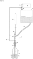
- the air return circuit 12 is placed in communication with the pressure chamber 14 to ensure a slow flow of the liquid.
- the control circuit 28 closes the tank shutter 16 and simultaneously opens the chamber shutter 15.
- the pressure applied inside the container 2 by the pressure chamber 14 and exerted on the liquid leaving the filling tube is such that it makes it possible to reduce the gravity flow of the liquid leaving the filling tube 11, by reducing the speed of the liquid leaving the filling tube 11; the impact of the liquid on the bottom of the container decreases, thus avoiding the creation of turbulence at the start of filling.
- the level of the liquid inside the container 2 thus rises gradually with an upper surface remaining practically flat.
- the air return circuit 12 When the outlet passage 11b of the filling tube 11 is immersed in the liquid, the air return circuit 12 is brought to atmospheric pressure to increase the flow of the liquid.
- the control circuit 28 closes the chamber shutter 15 and simultaneously opens the tank shutter 16 ( Fig. 6 ). It follows that the filling speed is accelerated without affecting the quality of the liquid since the liquid flowing from the outlet passage 11b of the filling tube is submerged.
- the filling tube 11 When the liquid level is such that the outlet passage 11b of the filling tube 11 is immersed in the liquid, then the filling tube 11 is reassembled while retaining the outlet passage 11b of the submerged liquid ( Fig. 7 ).
- the control circuit 28 thus controls the movement actuator 18 to raise the filling tube 11 towards its leveling position while keeping the outlet passage 11b of the filling tube 11 immersed in the liquid. filling continues without affecting the quality of the filling.
- the start of the rise of the filling tube 11 begins after a period determined by experimentation. Likewise, the ascent speed of the filling tube 11 is determined by experiment.
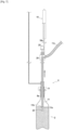
- the filling process ends during an end-of-filling phase occurring when the liquid level approaches the leveling position. Typically, this end of filling phase begins when the liquid level reaches the start of the neck.
- the air return circuit 12 is placed in communication with the pressure chamber 14 to slow down the flow of the liquid ( Fig. 8 ).
- the control circuit 28 closes the tank shutter 16 and simultaneously opens the chamber shutter 15.
- the pressure applied inside the container 2 by the pressure chamber 14 and exerted on the liquid leaving the filling tube is such that it makes it possible to reduce the gravity flow of the liquid leaving the filling tube 11, thus avoiding the creation of turbulence at the end of filling.
- the filling tube 11 continues to move upwards, under the action of the movement actuator 18, to its leveling position.
- the filling tube 11 is moved so that the outlet passage 11b of the filling tube 11 remains submerged.
- the filling tube 11 is moved so that in the leveling position, the lower end 11a of the filling tube is at the level of the lower end 8a of the spout tip 8 ( Fig. 9 ).
- the level of the liquid inside the container 2 thus rises gradually to stabilize at the same level as the lower end 8a of the filling tube.
- the method consists of waiting for the liquid level to stabilize at the lower end 11a of the filling tube 11.
- the liquid continues its path in the air return circuit 12 going up into the annular chamber 12a and even in part of the connection pipe 12b ( Fig. 10 ).
- the method consists of closing the air return circuit 12 as well as outlet passage 11b of the filling tube 11 to stop the exit of the liquid.
- the control circuit 28 controls the shutter actuator 25 to ensure the rise of the rod 22 relative to the filling tube 11 so that the shutter 23 can close the outlet passage 11b of the filling tube ( Fig. 11 ).
- the control circuit 28 controls the movement actuator 18 to raise the filling tube 11 so that the seal 17a cooperates with the nozzle end 8 to close the air return circuit 12 and in particular the annular chamber 12a.
- the filling tube 11 is raised to the high position known as complete closure as illustrated in Fig. 3 .
- control circuit 28 closes the chamber shutter 15 and opens the tank shutter 16 in order to relieve the pressure in the air return circuit 12.
- the filled container is released from the spout tip 8 after filling using the handling system 7, to allow the engagement of a new container to be filled.
- the object of the invention thus makes it possible to fill and bring to a desired level a container without using a vacuum or a vacuum pump.
- the filling level is carried out by pressure balance when the liquid level reaches the lower end of the filling tube 11.
Description
L'objet de l'invention concerne le domaine technique du remplissage de récipients de tout type connu en soi tels qu'en verre ou en matière plastique, à l'aide d'un liquide de remplissage de toute nature. L'objet de l'invention trouve une application particulièrement avantageuse pour le remplissage de récipients de tous types de formes et de formats par des produits sensibles à l'oxydation tel que les vins.The object of the invention relates to the technical field of filling containers of any type known per se, such as glass or plastic, using a filling liquid of any kind. The object of the invention finds a particularly advantageous application for filling containers of all types of shapes and formats with products sensitive to oxidation such as wines.
Dans l'état de la technique, il a été proposé de nombreuses solutions pour remplir et mettre à niveau un liquide à l'intérieur de récipients.In the state of the art, numerous solutions have been proposed for filling and leveling a liquid inside containers.
Par exemple, le brevet
Il doit tout d'abord être considéré que le remplissage de récipients utilisant le vide est susceptible d'affecter la qualité du liquide de remplissage en raison de l'aération du liquide. En effet, le vide modifie les équilibres gazeux de certains liquides et conduit à une perte des arômes. De plus, la qualité du liquide est aussi affectée par la recirculation du liquide qui se produit en présence du récipient sur le siège de réception et même en l'absence du récipient, avec un débit de recirculation plus faible. Par ailleurs, il apparaît que l'opération de remplissage s'avère en pratique notamment en fin d'opération de remplissage, relativement longue compte tenu de la création de bulles ou de mousse rendant difficile la mise à niveau du liquide.It should first be considered that filling containers using vacuum is likely to affect the quality of the filling liquid due to aeration of the liquid. Indeed, the vacuum modifies the gaseous balances of certain liquids and leads to a loss of aromas. In addition, the quality of the liquid is also affected by the recirculation of the liquid which occurs in the presence of the container on the receiving seat and even in the absence of the container, with a lower recirculation flow rate. Furthermore, it appears that the filling operation turns out in practice, particularly at the end of the filling operation, to be relatively long given the creation of bubbles or foam making it difficult to level the liquid.
Le document
La mise en oeuvre de la technique décrite par ce document conduit à une opération de remplissage relativement longue compte tenu notamment de la création de bulles ou de mousse en fin d'opération de remplissage.The implementation of the technique described by this document leads to a relatively long filling operation taking into account in particular the creation of bubbles or foam at the end of the filling operation.
Dans le secteur de la mise en bouteille du vin, il est connu que l'absorption d'oxygène par le vin doit être réduite autant que possible au cours de la phase de remplissage. Les machines d'embouteillage connues utilisent actuellement un procédé de remplissage qui prévoit essentiellement une étape préliminaire au cours de laquelle un gaz inerte tel que de l'azote est injecté à l'intérieur du récipient pour en chasser l'oxygène à l'aide d'un injecteur à tubes inséré partiellement dans le goulot du récipient.In the wine bottling industry it is known that the absorption of oxygen by the wine must be reduced as much as possible during the filling phase. Known bottling machines currently use a filling process which essentially provides a preliminary step during which an inert gas such as nitrogen is injected inside the container to drive out the oxygen using a tube injector partially inserted into the neck of the container.
Le goulot du récipient est ensuite scellé au moyen d'un robinet de remplissage qui comprend de manière coaxiale, la buse d'injection d'azote susmentionnée. Le vide est alors créé à l'intérieur du récipient et le vin est ensuite versé dans le récipient qui coule sur les surfaces des parois internes du récipient, de son goulot à son fond. Le niveau de remplissage correct est obtenu en aspirant la quantité de vin excédant du récipient. Ce procédé classique ci-dessus a été décrit par exemple dans la demande de brevet
La présente invention vise donc à remédier aux inconvénients de l'état de la technique en proposant une nouvelle technique de remplissage n'ayant pas recours à l'injection d'azote tout en limitant l'absorption d'oxygène par le liquide, ce procédé permettant un remplissage des récipients à un niveau souhaité et reproductible.The present invention therefore aims to remedy the drawbacks of the state of the art by proposing a new filling technique not requiring the injection of nitrogen while limiting the absorption of oxygen by the liquid, this process allowing containers to be filled to a desired and reproducible level.
Un autre objet de l'invention vise à permettre de remplir des récipients de toutes formes et de tous formats.Another object of the invention aims to make it possible to fill containers of all shapes and sizes.
Pour atteindre un tel objectif, l'objet de l'invention concerne un procédé de remplissage de récipients à l'aide d'un liquide de remplissage stocké dans une cuve et délivré à l'aide d'au moins une tête de remplissage comportant un embout de bec pourvu d'un siège d'appui pour un goulot d'un récipient, l'embout de bec étant traversé par un tube de remplissage raccordé à la cuve et délimitant avec l'embout de bec, au moins une partie d'un circuit de retour d'air, le tube de remplissage délimitant un passage de sortie pour le liquide ouvert ou fermé à l'aide d'un dispositif d'obturation, le procédé comportant les étapes suivantes pour le remplissage d'un récipient :
- amener le goulot du récipient en appui sur le siège en engageant l'embout de bec à l'intérieur du récipient ;
- translater le tube de remplissage à l'intérieur du récipient d'une position haute à une position basse à proximité du fond du récipient ;
- mettre en communication avec l'intérieur du récipient, le circuit de retour d'air mis à la pression atmosphérique pour qu'il se vide de son liquide ;
- ouvrir, lorsque le tube de remplissage occupe sa position basse, le passage de sortie du tube de remplissage en vue d'assurer la sortie du liquide et mettre en communication le circuit de retour d'air avec une chambre sous pression pour assurer un écoulement lent du liquide ;
- lorsque le passage de sortie du tube de remplissage est immergée dans le liquide, mettre le circuit de retour d'air à la pression atmosphérique pour augmenter l'écoulement du liquide ;
- déplacer le tube de remplissage en conservant immergé le passage de sortie du liquide, en direction d'une position de mise à niveau pour laquelle le tube de remplissage est engagé à l'intérieur du récipient selon une profondeur correspondant au niveau du liquide à l'intérieur du récipient ;
- lors de la phase de fin du remplissage, mettre en communication le circuit de retour d'air avec la chambre sous pression pour ralentir l'écoulement du liquide et déplacer le tube de remplissage jusqu'à sa position de mise à niveau ;
- attendre la stabilisation du niveau de liquide avec un retour de liquide dans le circuit de retour d'air avant de fermer le circuit de retour d'air ;
- et fermer le passage de sortie du tube de remplissage pour arrêter la sortie du liquide.
- bring the neck of the container to rest on the seat by engaging the nozzle tip inside the container;
- translating the filling tube inside the container from a high position to a low position near the bottom of the container;
- put in communication with the interior of the container, the air return circuit brought to atmospheric pressure so that it empties its liquid;
- open, when the filling tube is in its low position, the outlet passage of the filling tube in order to ensure the exit of the liquid and put the air return circuit into communication with a pressure chamber to ensure slow flow some cash ;
- when the outlet passage of the filling tube is immersed in the liquid, bring the air return circuit to atmospheric pressure to increase the flow of liquid;
- move the filling tube while keeping the liquid outlet passage submerged, towards a leveling position for which the filling tube is engaged inside the container at a depth corresponding to the level of the liquid at the interior of container;
- during the end of filling phase, put the air return circuit into communication with the pressure chamber to slow down the flow of the liquid and move the filling tube to its leveling position;
- wait for the liquid level to stabilize with a return of liquid in the return air circuit before closing the return air circuit;
- and close the outlet passage of the filling tube to stop the outflow of liquid.
De plus, le procédé selon l'invention comporte en outre en combinaison au moins l'une et/ou l'autre des caractéristiques additionnelles suivantes :
- le récipient est dégagé de l'embout de bec après son remplissage avant l'engagement d'un nouveau récipient à remplir ;
- le tube de remplissage est déplacé afin qu'en position de mise à niveau, l'extrémité inférieure du tube de remplissage se trouve au niveau de l'extrémité inférieure de l'embout de bec ;
- le siège d'appui est monté en position réglable par rapport à l'extrémité inférieure de l'embout de bec pour régler le niveau du liquide à l'intérieur du récipient ;
- le tube de remplissage est déplacé de sa position de mise à niveau jusqu'à la position haute pour assurer la fermeture du circuit de retour d'air intervenant automatiquement lorsque le tube de remplissage passe de sa position de mise à niveau à la position haute ;
- le tube de remplissage est déplacé de manière que la position haute correspond à la position de mise à niveau ;
- la translation du tube de remplissage à l'intérieur du récipient de la position haute à la position basse assure la mise en communication du circuit de retour d'air avec l'intérieur du récipient ;
- le récipient est en appui étanche sur le siège au moins tant que le passage de sortie du tube de remplissage est ouvert ;
- le passage de sortie du tube de remplissage est ouvert ou fermé par un obturateur porté par une tige déplaçable en translation par rapport au tube afin d'ouvrir ou de fermer le passage de sortie en fonction de la position la tige par rapport au tube de remplissage.
- the container is released from the spout tip after filling before engaging a new container to fill;
- the filling tube is moved so that in the leveling position, the lower end of the filling tube is level with the lower end of the spout tip;
- the support seat is mounted in an adjustable position relative to the lower end of the nozzle tip to adjust the level of the liquid inside the container;
- the filling tube is moved from its leveling position to the high position to ensure the closure of the air return circuit occurring automatically when the filling tube moves from its leveling position to the high position;
- the filling tube is moved so that the high position corresponds to the leveling position;
- the translation of the filling tube inside the container from the high position to the low position ensures communication of the air return circuit with the interior of the container;
- the container rests tightly on the seat at least as long as the outlet passage of the filling tube is open;
- the outlet passage of the filling tube is opened or closed by a shutter carried by a rod movable in translation relative to the tube in order to open or close the outlet passage depending on the position of the rod relative to the filling tube .
Un autre objet de l'invention est de proposer une machine de remplissage de récipients à l'aide d'un liquide de remplissage stocké dans une cuve, comportant au moins une tête de remplissage, chaque tête de remplissage comportant :
- un embout de bec pourvu d'un siège d'appui pour un goulot d'un récipient ;
- un tube de remplissage raccordé à la cuve et traversant l'embout de bec pour délimiter avec l'embout de bec, une partie d'un circuit de retour d'air connecté soit à la pression atmosphérique via un obturateur de cuve, soit à une chambre sous pression via un obturateur de chambre, le tube de remplissage étant déplaçable verticalement à l'aide d'un actionneur de déplacement entre d'une part, une position haute et d'autre part, une position basse à proximité du fond du récipient, le tube de remplissage délimitant un passage de sortie pour le liquide ouvert ou fermé à l'aide d'un dispositif d'obturation ;
- un système d'étanchéité assurant la fermeture du circuit de retour d'air lorsque le tube de remplissage occupe la position haute de fermeture ;
- un circuit de commande relié à l'obturateur de chambre, à l'obturateur de cuve, à l'actionneur de déplacement, au dispositif d'obturation et au système d'étanchéité pour :
- * lors d'une phase de remplissage initiale, déplacer le tube de remplissage de sa position haute de fermeture à sa position basse et piloter le dispositif d'obturation pour ouvrir le passage de sortie du tube de remplissage, et mettre en communication le circuit de retour d'air avec la chambre sous pression ;
- * lorsque le passage de sortie du tube de remplissage est immergée dans le liquide, mettre le circuit de retour d'air à la pression atmosphérique et déplacer le tube de remplissage en direction de sa position de mise à niveau en conservant immergée le passage de sortie du liquide ;
- * lors de la phase de fin du remplissage, mettre en communication le circuit de retour d'air avec la chambre sous pression et amener le tube de remplissage à une position de mise à niveau du liquide à l'intérieur du récipient, avec un retour de liquide dans le circuit de retour d'air, piloter le système d'étanchéité pour fermer du circuit de retour d'air et piloter le dispositif d'obturation pour fermer le passage de sortie du liquide.
- a spout tip provided with a support seat for a neck of a container;
- a filling tube connected to the tank and passing through the spout tip to delimit with the spout tip, part of an air return circuit connected either to atmospheric pressure via a tank shutter, or to a pressure chamber via a chamber shutter, the filling tube being movable vertically using a movement actuator between, on the one hand, a high position and on the other hand, a low position near the bottom of the container , the filling tube delimiting an outlet passage for the liquid open or closed using a closing device;
- a sealing system ensuring the closure of the air return circuit when the filling tube occupies the upper closed position;
- a control circuit connected to the chamber shutter, the tank shutter, the movement actuator, the shutter device and the sealing system for:
- * during an initial filling phase, move the filling tube from its upper closed position to its lower position and control the closing device to open the outlet passage of the filling tube, and put the filling circuit into communication air return with the chamber under pressure;
- * when the outlet passage of the filling tube is immersed in the liquid, bring the air return circuit to atmospheric pressure and move the filling tube towards its leveling position while keeping the outlet passage submerged some cash ;
- * during the end of filling phase, put the air return circuit in communication with the pressure chamber and bring the filling tube to a position for leveling the liquid inside the container, with a return of liquid in the air return circuit, control the sealing system to close the air return circuit and control the closing device to close the liquid outlet passage.
De plus, la machine selon l'invention peut présenter en outre en combinaison au moins l'une et/ou l'autre des caractéristiques additionnelles suivantes :
- le dispositif d'obturation comporte une tige montée à l'intérieur du tube de remplissage et équipée à sa partie inférieure, d'un obturateur et déplaçable en translation par rapport au tube de remplissage à l'aide d'un actionneur de remplissage afin que l'obturateur puisse ouvrir ou fermer le passage de sortie du tube de remplissage en fonction de la position de la tige ;
- le système d'étanchéité comporte un joint d'étanchéité porté par la tige pour venir fermer le circuit de retour d'air lorsque le tube de remplissage passe de sa position de mise à niveau à sa position haute de fermeture ;
- le siège d'appui est monté avec une possibilité de réglage par rapport à l'extrémité inférieure de l'embout de bec pour permettre de régler le niveau du liquide dans le récipient ;
- le tube de remplissage est pourvu d'un support pour la tige et pour l'actionneur de remplissage ;
- la machine comporte un système de manipulation des récipients permettant d'engager chaque récipient dans l'embout de bec et de dégager chacun des récipients après leur remplissage.
- the shutter device comprises a rod mounted inside the filling tube and equipped at its lower part with a shutter and movable in translation relative to the filling tube using a filling actuator so that the shutter can open or close the outlet passage of the filling tube depending on the position of the rod;
- the sealing system comprises a seal carried by the rod to close the air return circuit when the filling tube passes from its leveling position to its high closing position;
- the support seat is mounted with adjustment possibility relative to the lower end of the spout tip to allow the level of the liquid in the container to be adjusted;
- the filling tube is provided with a support for the rod and for the actuator filling ;
- the machine includes a container handling system making it possible to engage each container in the nozzle tip and to release each of the containers after they have been filled.
Diverses autres caractéristiques ressortent de la description faite ci-dessous en référence aux dessins annexés qui montrent, à titre d'exemples non limitatifs, des formes de réalisation de l'objet de l'invention.Various other characteristics emerge from the description given below with reference to the appended drawings which show, by way of non-limiting examples, embodiments of the object of the invention.
-
[
Fig. 1 ] LaFigure 1 est une vue schématique de la machine de remplissage conforme à l'invention avant engagement du récipient sur la tête de remplissage.[Fig. 1 ] ThereFigure 1 is a schematic view of the filling machine according to the invention before engagement of the container on the filling head. -
[
Fig. 2 ] LaFigure 2 est une vue partielle à grande échelle, de la tête de remplissage, avec le tube de remplissage en position fermée et avec le circuit de retour d'air en position d'ouverture.[Fig. 2 ] ThereFigure 2 is a large-scale partial view of the filling head, with the filling tube in the closed position and with the air return circuit in the open position. -
[
Fig. 3 ] LaFigure 3 est une vue partielle à grande échelle, de la tête de remplissage, avec le tube de remplissage en position fermée et avec le circuit de retour d'air en position fermée.[Fig. 3 ] ThereFigure 3 is a large-scale partial view of the filling head, with the filling tube in the closed position and with the air return circuit in the closed position. -
[
Fig. 4 ] LaFigure 4 illustre la machine de remplissage au début de la phase de remplissage montrant le tube de remplissage en position basse.[Fig. 4 ] ThereFigure 4 illustrates the filling machine at the start of the filling phase showing the filling tube in the down position. -
[
Fig. 5 ] LaFigure 5 illustre la machine de remplissage dans une phase de début de remplissage pour laquelle le liquide s'écoule en mode lent.[Fig. 5 ] ThereFigure 5 illustrates the filling machine in a start-of-filling phase for which the liquid flows in slow mode. -
[
Fig. 6 ] LaFigure 6 est une vue de la machine de remplissage lors d'une phase de remplissage pour laquelle le liquide s'écoule en mode accéléré.[Fig. 6 ] ThereFigure 6 is a view of the filling machine during a filling phase for which the liquid flows in accelerated mode. -
[
Fig. 7 ] LaFigure 7 est une vue de la machine de remplissage analogue à laFig. 6 montrant l'évolution du remplissage.[Fig. 7 ] ThereFigure 7 is a view of the filling machine similar to theFig. 6 showing the evolution of the filling. -
[
Fig. 8 ] LaFigure 8 illustre la machine de remplissage en fin de la phase de remplissage pour laquelle le liquide s'écoule en mode lent.[Fig. 8 ] ThereFigure 8 illustrates the filling machine at the end of the filling phase for which the liquid flows in slow mode. -
[
Fig. 9 ] LaFigure 9 est une vue partielle à grande échelle, de la tête de remplissage, montrant le tube de remplissage à sa position de mise à niveau.[Fig. 9 ] ThereFigure 9 is a partial, large-scale view of the filling head, showing the filling tube in its leveling position. -
[
Fig. 10 ] LaFigure 10 est une vue partielle à grande échelle, de la tête de remplissage, montrant le cheminement du liquide dans le circuit de retour d'air.[Fig. 10 ] ThereFigure 10 is a large-scale partial view of the filling head, showing the path of the liquid in the air return circuit. -
[
Fig. 11 ] LaFigure 11 est une vue schématique de la machine de remplissage après remplissage d'un récipient, avec le circuit de retour d'air en position fermée et le tube de remplissage en position fermée.[Fig. 11 ] ThereFigure 11 is a schematic view of the filling machine after filling a container, with the air return circuit in the closed position and the filling tube in the closed position.
Tel que cela ressort plus précisément de la
La machine de remplissage I comporte une cuve de stockage 3 pour le liquide 1, maintenue à une pression de régulation par tous moyens appropriés 4 tels que par exemple par un régulateur de pression. Typiquement, la cuve 3 est maintenue à une pression correspondant à la pression atmosphérique.The filling machine I comprises a
La machine de remplissage I comporte également au moins une et d'une manière générale, plusieurs têtes de remplissage 6 adaptées pour remplir par gravité, chacune un récipient 2 par le liquide 1 sortant de la cuve de stockage 3 située à un niveau plus élevé par rapport au niveau de montage des têtes de remplissage 6. Après son remplissage, chaque récipient 2 est évacué et remplacé par un nouveau récipient en vue de son remplissage. La machine de remplissage I comporte à cet effet, un système 7 de manipulation des récipients permettant d'amener chaque récipient 2 à une tête de remplissage 6 et de dégager chacun des récipients après leur remplissage. Ce système de manipulation 7 des récipients peut être réalisé de toute manière appropriée. Avantageusement, ce système de manipulation 7 comporte pour chaque tête de remplissage 6, une pince de préhension permettant le déplacement des récipients par leur col.The filling machine I also comprises at least one and generally several filling
La machine de remplissage I n'est pas décrite plus précisément car elle peut prendre différentes formes ou configurations en fonction en particulier du nombre de têtes de remplissage 6. Selon la description qui suit, seul le fonctionnement d'une tête de remplissage 6 est décrit, mais il est clair que l'objet de l'invention peut s'appliquer à une machine comportant une série de têtes de remplissage par exemple distribuées selon une ligne ou à sa périphérie afin de réaliser la machine sous la forme d'un carrousel.The filling machine I is not described more precisely because it can take different shapes or configurations depending in particular on the number of filling heads 6. According to the description which follows, only the operation of a filling
Chaque tête de remplissage 6 comporte un embout de bec 8 pourvu d'un siège d'appui 9 pour le goulot du récipient. L'embout de bec 8 est réalisé par un tube ou une canule dont la section est adaptée pour pouvoir être introduit dans le récipient 2 par son goulot. Cet embout de bec 8 présente une extrémité inférieure 8a (
L'embout de bec 8 est équipé extérieurement du siège d'appui 9 qui est pourvu d'un joint d'appui 10 pour le récipient en position de remplissage. Ainsi, chaque récipient 2 prend appui par son goulot ou plus précisément par sa surface de bague 2d sur le joint d'appui 10 de manière à assurer une étanchéité entre l'embout de bec 8 et le goulot 2c du récipient. Chaque récipient 2 est ainsi déplacé par le système de manipulation 7 pour engager le goulot autour de l'embout de bec 8 et venir par sa surface de bague 2d, en appui sur le joint 10. Au terme de l'opération de remplissage, chaque récipient 2 rempli est évacué par le système de manipulation 7 qui assure l'amenée du récipient suivant à la tête de remplissage.The
Selon une caractéristique avantageuse de réalisation, le siège d'appui 9 est monté avec une possibilité de réglage par rapport à l'extrémité inférieure 8a de l'embout de bec 8 pour permettre de régler le niveau du liquide dans le récipient. A cet effet, le siège d'appui 9 est monté coulissant sur l'embout de bec 8 avec un système de blocage dans une position prédéterminée de tous types connus en soi. Par exemple, l'embout de bec 8 peut comporter des graduations pour faciliter le positionnement dans une position définie, du siège d'appui 9 par rapport à l'extrémité inférieure 8a de l'embout de bec 8.According to an advantageous embodiment, the
Chaque embout de bec 8 est traversé par un tube de remplissage 11 communiquant avec la cuve de stockage 3 et monté mobile en translation verticale. Le tube de remplissage 11 traverse l'embout de bec 8 pour délimiter avec l'embout de bec, une partie 12a d'un circuit de retour d'air 12 en communication avec l'intérieur du récipient afin de le placer à une valeur de pression déterminée en fonction du cycle de remplissage, comme cela sera expliqué dans la suite de la description. A cet effet, l'embout de bec 8 et le tube de remplissage 11 s'étendent de manière coaxiale l'un à l'autre en délimitant entre eux, une chambre annulaire 12a faisant partie du circuit de retour d'air 12 (
Ce circuit de retour d'air 12 comporte également une conduite de raccordement 12b avec la chambre annulaire 12a et connectée soit à la pression atmosphérique soit à une chambre sous pression 14 via un obturateur de chambre 15. Avantageusement, la conduite de raccordement 12b est connectée via un obturateur de cuve 16, au ciel 3a de la cuve 3 dont la pression est maintenue égale à la pression atmosphérique. Ainsi, le circuit de retour d'air 12 est placé soit à la pression atmosphérique (via l'obturateur de cuve 16) soit à une valeur de pression supérieure à la pression atmosphérique (via l'obturateur de chambre 15).This
Selon une autre caractéristique de l'invention, un système d'étanchéité 17 assure la fermeture du circuit de retour d'air 12 lorsque le tube de remplissage 11 occupe une position haute (
Le tube de remplissage 11 comporte une extrémité inférieure 11a délimitant un passage de sortie 11b pour le liquide. L'extrémité inférieure 11a s'étend toujours en dessous du siège d'appui 9. Ainsi, le tube de remplissage 11 s'étend ainsi en saillie à partir du siège d'appui 9 permettant l'introduction du tube de remplissage 11 par son extrémité inférieure 11a à l'intérieur du récipient 2. Dans l'exemple illustré, le tube de remplissage 11 est un tube rigide relié au fond de la cuve 3 à l'aide d'un flexible 11c.The filling
Le tube de remplissage 11 est déplaçable selon une direction verticale à l'aide d'un actionneur de déplacement 18 entre une position haute et une position basse définie par rapport à la profondeur d'engagement du tube de remplissage à l'intérieur du récipient. La position haute du tube de remplissage 11 correspond à la position dans un cycle de remplissage, pour laquelle le tube de remplissage 11 occupe la position la plus haute. Cette position haute peut correspondre à la position de mise à niveau pour laquelle le tube de remplissage 11 est engagé à l'intérieur du récipient selon une profondeur correspondant au niveau du liquide à atteindre à l'intérieur du récipient. La distance entre le siège d'appui 9 et l'extrémité inférieure 11a du tube de remplissage correspond ainsi à la hauteur finale du liquide à l'intérieur du récipient 2. Selon une variante préférée de mise en oeuvre, en position de mise à niveau, l'extrémité inférieure 11a du tube de remplissage se trouve au niveau de l'extrémité inférieure 8a de l'embout de bec 8 comme illustré à la
La position haute du tube de remplissage 11 peut correspondre également selon une variante préférée de réalisation décrite en détail dans la suite de la description, à une position du tube de remplissage plus haute que la position de mise à niveau et pour laquelle le tube de remplissage 11 obture le circuit de retour d'air 12. Dans cette position haute dite d'obturation complète illustrée à la
La position basse du tube de remplissage 11 correspond à un positionnement de l'extrémité inférieure 11a du tube de remplissage au niveau du fond 2a du récipient. De préférence, dans cette position basse, l'extrémité inférieure 11a du tube de remplissage n'est pas en contact avec le fond du récipient mais se trouve à proximité du fond piqué.The lower position of the filling
L'actionneur de déplacement 18 possède une course de déplacement permettant de positionner l'extrémité inférieure 11a du tube de remplissage 11 entre cette position haute et cette position basse. Dans l'exemple illustré sur les dessins, l'actionneur 18 est un vérin électrique mais il est clair que cet actionneur peut être réalisé de toute manière appropriée. Cet actionneur 18 comporte une tige d'actionnement 18a coulissant dans un corps 18b et agissant sur un support 20 supportant le tube de remplissage 11. Tel que cela ressort des dessins, l'extrémité supérieure du tube de remplissage 11 est fixée sur le support 20.The movement actuator 18 has a movement stroke making it possible to position the
Selon une autre caractéristique de l'invention, le passage de sortie 11b du tube de remplissage 11 est ouvert ou fermé à l'aide d'un dispositif d'obturation 21 de tous types. Dans l'exemple de réalisation illustré sur les dessins, le dispositif d'obturation 21 comporte une tige 22 montée de manière coaxiale à l'intérieur du tube de remplissage 11. Cette tige 22 est équipée à sa partie inférieure, d'un obturateur 23 adapté pour ouvrir ou fermer le passage de sortie 11b du tube de remplissage en fonction de la position de la tige. La tige 22 est montée déplaçable en translation par rapport au tube de remplissage 11 à l'aide d'un actionneur 25 qui contrôle au moins l'obturation du passage de sortie 11b du tube de remplissage. Cet actionneur d'obturation 25 déplace la tige 22 afin que l'obturateur 23 puisse ouvrir ou fermer le passage de sortie 11b du tube de remplissage. Pour passer de la position ouverte à la position fermée du passage de sortie 11b, la tige 22 est déplacée vers le haut par rapport au tube de remplissage 11 de manière que l'obturateur 23 vient coopérer avec l'extrémité inférieure 11a afin de fermer son passage de sortie 11b. Pour passer de la position fermée à la position ouverte du passage de sortie 11b, la tige 22 est déplacée vers le bas par rapport au tube de remplissage 11 de manière que l'obturateur 23 ne coopère pas avec l'extrémité inférieure 11a afin d'ouvrir son passage de sortie 11b. Avantageusement, la course de la tige 22 est adaptée de manière qu'en position d'ouverture, l'obturateur 23 ne réduit pas le passage de sortie 11b du tube de remplissage 11.According to another characteristic of the invention, the
La tige 22 est guidée en coulissement par le support 20 sur lequel est avantageusement monté l'actionneur d'obturation 25. Par exemple, l'actionneur d'obturation 25 est réalisé par un actionneur électrique ou pneumatique.The
Selon une caractéristique avantageuse de l'invention, la tige 22 fait partie du système d'étanchéité 17 qui assure la fermeture du circuit de retour d'air 12 lorsque le tube de remplissage 11 occupe la position haute dite d'obturation complète (
Selon une variante avantageuse de réalisation, l'obturateur 23 et le joint d'étanchéité 17a sont réalisés par un joint d'étanchéité commun porté par l'extrémité inférieure de la tige 22. Ce joint d'étanchéité commun 23, 17a possède une forme tronconique avec sa partie centrale obturant le tube de remplissage 11 tandis que sa partie périphérique ferme la chambre annulaire 12a délimitée entre le tube de remplissage 11 et l'embout de bec 8. Ce joint d'étanchéité commun 23, 17a est réalisé de toute manière appropriée pour réaliser les fonctions d'étanchéité décrites. Pour passer de la position ouverte à la position fermée du circuit de retour d'air 12, le tube de remplissage 11 est déplacé vers le haut par rapport à l'embout de bec 8 de manière que le système d'étanchéité 17 assure la fermeture de la partie inférieure de la chambre annulaire 12a délimitée entre l'embout de bec 8 et le tube de remplissage 11. Dans cette position fermée illustrée à la
La machine de remplissage I comporte également un circuit de commande 28 relié à l'obturateur de chambre 15, à l'obturateur de cuve 16, à l'actionneur de déplacement 18 du tube de remplissage 11 et à l'actionneur d'obturation 25 permettant l'ouverture ou la fermeture du passage de sortie du tube de remplissage 11. Le circuit de commande 28 permet de piloter le fonctionnement de l'obturateur de chambre 15, de l'obturateur de cuve 16, de l'actionneur de déplacement 18 du tube de remplissage 11 et de l'actionneur d'obturation 25 pour mettre en oeuvre un procédé de remplissage conforme à l'invention. Le circuit de commande 28 pilote également le système d'étanchéité 17 qui assure la fermeture du circuit de retour d'air 12. Dans l'exemple illustré, le système d'étanchéité 17 est contrôlé par le tube de remplissage 11 dont le déplacement est piloté par l'actionneur de déplacement 18.The filling machine I also includes a
La description qui suit décrit un cycle de remplissage d'un récipient 2 selon le procédé conforme à l'invention mis en oeuvre avec la machine I décrite ci-dessus.The following description describes a filling cycle of a
La
Le procédé de remplissage consiste à amener le goulot 2c du récipient 2 en appui sur le siège 9 de la tête de remplissage tout en engageant l'embout de bec 8 à l'intérieur du récipient 2. A cet effet, le système 7 de manipulation déplace le récipient 2 pour amener sa surface de bague 2d en appui sur le siège 9. Comme illustré plus précisément à la
Il est à noter que la descente du tube de remplissage 11 conduit à libérer l'étanchéité entre le tube de remplissage 11 et l'embout de bec 8 puisque le joint d'étanchéité 17a ne coopère plus avec l'embout de bec 8 (
Lorsque le tube de remplissage 11 occupe sa position basse, le passage de sortie 11b du tube de remplissage est ouvert en vue d'assurer la sortie du liquide (
Avantageusement, de manière concomitante à l'ouverture du passage de sortie du tube de remplissage, le circuit de retour d'air 12 est mis en communication avec la chambre sous pression 14 pour assurer un écoulement lent du liquide. Le circuit de commande 28 ferme l'obturateur de cuve 16 et simultanément ouvre l'obturateur de chambre 15. La pression appliquée à l'intérieur du récipient 2 par la chambre sous pression 14 et exercée sur le liquide sortant du tube de remplissage est telle qu'elle permet de réduire l'écoulement gravitaire du liquide sortant du tube de remplissage 11, en diminuant la vitesse du liquide sortant du tube de remplissage 11; l'impact du liquide sur le fond du récipient diminue, évitant ainsi la création de turbulences en début de remplissage. Le niveau du liquide à l'intérieur du récipient 2 s'élève ainsi progressivement avec une surface supérieure restant pratiquement plane.Advantageously, concomitantly with the opening of the outlet passage of the filling tube, the
Lorsque le passage de sortie 11b du tube de remplissage 11 est immergée dans le liquide, le circuit de retour d'air 12 est mis à la pression atmosphérique pour augmenter l'écoulement du liquide. Le circuit de commande 28 ferme l'obturateur de chambre 15 et simultanément ouvre l'obturateur de cuve 16 (
Lorsque le niveau du liquide est tel que le passage de sortie 11b du tube de remplissage 11 est immergée dans le liquide, alors le tube de remplissage 11 est remonté en conservant le passage de sortie 11b du liquide immergé (
Le procédé de remplissage se termine lors d'une phase de fin de remplissage intervenant lorsque le niveau du liquide se rapproche de la position de mise à niveau. Typiquement, cette phase de fin de remplissage débute lorsque le niveau du liquide arrive au début du col. Lors de la phase de fin du remplissage, le circuit de retour d'air 12 est mis en communication avec la chambre sous pression 14 pour ralentir l'écoulement du liquide (
Le tube de remplissage 11 poursuit son déplacement vers le haut, sous l'action de l'actionneur de déplacement 18, jusqu'à sa position de mise à niveau. Bien entendu, le tube de remplissage 11 est déplacé de manière que le passage de sortie 11b du tube de remplissage 11 reste immergé. Selon une variante avantageuse de réalisation, le tube de remplissage 11 est déplacé afin qu'en position de mise à niveau, l'extrémité inférieure 11a du tube de remplissage se trouve au niveau de l'extrémité inférieure 8a de l'embout de bec 8 (
Le procédé consiste à attendre la stabilisation du niveau de liquide au niveau de l'extrémité inférieure 11a du tube de remplissage 11. Le liquide poursuit son chemin dans le circuit de retour d'air 12 en remontant dans la chambre annulaire 12a et voire dans une partie de la conduite de raccordement 12b (
Après l'opération de mise à niveau, le procédé consiste à fermer le circuit de retour d'air 12 ainsi que passage de sortie 11b du tube de remplissage 11 pour arrêter la sortie du liquide. A cet effet, le circuit de commande 28 pilote l'actionneur d'obturation 25 pour assurer la remontée de la tige 22 par rapport au tube de remplissage 11 afin que l'obturateur 23 puisse fermer le passage de sortie 11b du tube de remplissage (
Le remplissage du récipient étant terminé, le circuit de commande 28 ferme l'obturateur de chambre 15 et ouvre l'obturateur de cuve 16 afin de décharger la pression dans le circuit de retour d'air 12. Le récipient rempli est dégagé de l'embout de bec 8 après son remplissage à l'aide du système de manipulation 7, pour permettre l'engagement d'un nouveau récipient à remplir.The filling of the container being completed, the
L'objet de l'invention permet ainsi de remplir et mettre à un niveau souhaité, un récipient sans utiliser de vide ou une pompe à vide. Le niveau de remplissage est effectué par équilibre de pression lorsque le niveau de liquide atteint l'extrémité inférieure du tube de remplissage 11.The object of the invention thus makes it possible to fill and bring to a desired level a container without using a vacuum or a vacuum pump. The filling level is carried out by pressure balance when the liquid level reaches the lower end of the filling
L'invention n'est pas limitée aux exemples décrits et représentés car diverses modifications peuvent y être apportées sans sortir de son cadre.The invention is not limited to the examples described and represented because various modifications can be made without departing from its scope.
Claims (15)
- A method for filling containers (2) using a filling liquid (1) stored in a tank (3) and delivered using at least one filling head (6) including a spout endpiece (8) provided with a bearing seat (9) for a neck of a container, the spout endpiece (8) being crossed by a filling tube (11) connected to the tank and delimiting with the spout endpiece, at least part of an air return circuit (12), the filling tube delimiting an exit passage (11b) for the liquid which is opened or closed by means of an obturation device (21), the method including the following steps for the filling of a container:- making the neck of the container bear on the seat (9) by engaging the spout endpiece of the spout (8) inside the container (2);- translating the filling tube (11) inside the container from a high position to a low position in the vicinity of the bottom (2a) of the container;- putting in communication with the interior of the container, the air return circuit (12) put at atmospheric pressure so that it empties of its liquid;- when the filling tube (11) occupies its low position, opening the exit passage (11b) of the filling tube in order to ensure the exit of the liquid and put the air return circuit (12) in communication with a pressurized chamber (14) to ensure a slow flow of the liquid;- when the exit passage (11b) of the filling tube (11) is immersed in the liquid, putting the air return circuit (12) at atmospheric pressure to increase the flow of the liquid;- moving the filling tube (11) while keeping the liquid exit passage (11b) immersed, towards a leveling position for which the filling tube is engaged inside the container at a depth corresponding to the level of the liquid inside the container;- during the filling end phase, putting the air return circuit (12) in communication with the pressurized chamber (14) to slow down the flow of the liquid and move the filling tube (11) to its leveling position;- waiting for the stabilization of the liquid level with a return of liquid in the air return circuit (12) before closing the air return circuit;- and closing the exit passage (11b) of the filling tube to stop the exit of theliquid.
- The filling method according to claim 1, according to which the container (2) is disengaged from the spout endpiece (8) after its filling before the engagement of a new container to be filled.
- The filling method according to any of the preceding claims, according to which the filling tube (11) is moved so that, in the leveling position, the lower end (11a) of the filling tube is at the level of the lower end (8a) of the spout endpiece (8).
- The filling method according to any of the preceding claims, according to which the bearing seat (9) is mounted in an adjustable position relative to the lower end (8a) of the spout endpiece (8) to adjust the level of the liquid inside the container.
- The filling method according to any of the preceding claims, according to which the filling tube (11) is moved from its leveling position to the high position in order to ensure the closing of the air return circuit (12) occurring automatically when the filling tube switches from its leveling position to the high position.
- The filling method according to any of claims 1 to 5, according to which the filling tube (11) is moved such that the high position corresponds to the leveling position.
- The filling method according to any of the preceding claims, according to which the translation of the filling tube (11) inside the container from the high position to the low position ensures the communication of the air return circuit (12) with the interior of the container.
- The filling method according to any of the preceding claims, according to which the container (2) is sealingly bearing on the seat (9) at least as long as the exit passage (11b) of the filling tube (11) is open.
- The filling method according to any one of the preceding claims, according to which the exit passage (11b) of the filling tube is opened or closed by an obturator (23) carried by a rod (22) movable in translation relative to the tube in order to open or close the exit passage depending on the position of the rod (22) relative to the filling tube (11).
- A machine for filling containers (2) using a filling liquid (1) stored in a tank (3), including at least one filling head (6), each filling head including:- a spout endpiece (8) provided with a bearing seat (9) for a neck of a container;- a filling tube (11) connected to the tank and passing through the spout endpiece (8) to delimit with the spout endpiece, part (12a) of an air return circuit (12) connected either to the atmospheric pressure via a tank obturator (16), or to a pressurized chamber (14) via a chamber obturator (15), the filling tube (11) being vertically movable by means of a displacement actuator (18) between, on the one hand, a high position and, on the other hand, a low position in the vicinity of the bottom of the container, the filling tube (11) delimiting an exit passage (11b) for the liquid which is opened or closed by means of an obturation device (21);- a sealing system (17) ensuring the closing of the air return circuit (12) when the filling tube (11) occupies the high closing position;- a control circuit (28) connected to the chamber obturator (15), to the tank obturator (16), to the displacement actuator (18), to the obturation device (21) and to the sealing system (17) for:* moving the filling tube (11), during an initial filling phase, from its high closing position to its low position and driving the obturation device (21) to open the exit passage (11b) of the filling tube (11), and putting the air return circuit (12) in communication with the pressurized chamber (14);* putting the air return circuit (12), when the exit passage (11b) of the filling tube is immersed in the liquid, to atmospheric pressure and moving the filling tube (11) towards its leveling position while keeping the liquid exit passage (11b) immersed;* putting the air return circuit (12), during the filling end phase, in communication with the pressurized chamber (14) and bringing the filling tube (11) to a leveling position of the liquid inside the container, with a return of liquid in the air return circuit (12), driving the sealing system (17) to close the air return circuit and driving the obturation device (21) to close the liquid exit passage.
- The filling machine according to the preceding claim, according to which the obturation device (21) includes a rod (22) mounted inside the filling tube (11) and equipped at its lower part with an obturator (23) and movable in translation relative to the filling tube (11) by means of a filling actuator (25) so that the obturator (23) can open or close the exit passage (11b) of the filling tube (11) depending on the position of the rod.
- The filling machine according to any of claims 10 or 11, according to which the sealing system (17) includes a seal (17a) carried by the rod (22) to close the air return circuit (12) when the filling tube (11) switches from its leveling position to its high closing position.
- The filling machine according to any of claims 10 to 12, according to which the bearing seat (9) is mounted with a possibility of adjustment relative to the lower end (8a) of the spout endpiece ( 8) to allow adjusting the level of the liquid in the container.
- The filling machine according to any of claims 11 to 13, according to which the filling tube (11) is provided with a support (20) for the rod (22) and for the filling actuator (25).
- The filling machine according to any of claims 10 to 14, according to which it includes a container handling system (7) for engaging each container (2) in the spout endpiece (8) and releasing each of the containers after their filling.
Applications Claiming Priority (2)
| Application Number | Priority Date | Filing Date | Title |
|---|---|---|---|
| FR1910323A FR3101074B1 (en) | 2019-09-19 | 2019-09-19 | Method and machine for filling a container to a desired level of liquid |
| PCT/FR2020/051605 WO2021053297A1 (en) | 2019-09-19 | 2020-09-17 | Method and machine for filling a container to a desired liquid level |
Publications (3)
| Publication Number | Publication Date |
|---|---|
| EP4031479A1 EP4031479A1 (en) | 2022-07-27 |
| EP4031479C0 EP4031479C0 (en) | 2023-10-11 |
| EP4031479B1 true EP4031479B1 (en) | 2023-10-11 |
Family
ID=69172948
Family Applications (1)
| Application Number | Title | Priority Date | Filing Date |
|---|---|---|---|
| EP20820483.4A Active EP4031479B1 (en) | 2019-09-19 | 2020-09-17 | Method and machine for filling a container to a desired liquid level |
Country Status (4)
| Country | Link |
|---|---|
| US (1) | US11745992B2 (en) |
| EP (1) | EP4031479B1 (en) |
| FR (1) | FR3101074B1 (en) |
| WO (1) | WO2021053297A1 (en) |
Families Citing this family (1)
| Publication number | Priority date | Publication date | Assignee | Title |
|---|---|---|---|---|
| IT202100016190A1 (en) * | 2021-06-21 | 2022-12-21 | Gai Macch S P A | METHOD AND GROUP OF FILLING A BOTTLE WITH AN EDIBLE LIQUID |
Family Cites Families (20)
| Publication number | Priority date | Publication date | Assignee | Title |
|---|---|---|---|---|
| US1978002A (en) | 1931-04-17 | 1934-10-23 | Horix Mfg Company | Filling machine and method of filling containers |
| US2794453A (en) * | 1955-11-14 | 1957-06-04 | F Wenge Ets | Filling heads for bottling machine |
| GB972916A (en) * | 1961-02-15 | 1964-10-21 | Karl Kiefer Machine Company | Filling head for filling containers such as bottles |
| DE1185497B (en) | 1961-06-30 | 1965-01-14 | Holstein & Kappert Maschf | Valve-controlled filling element for counter pressure bottle fillers |
| DE1432361A1 (en) * | 1964-10-06 | 1969-09-04 | Holstein & Kappert Maschf | Process for filling beer or other carbonated beverages |
| US3516455A (en) * | 1967-05-01 | 1970-06-23 | Automatic Sprinkler Corp | Container-filling apparatus |
| DE2234120C3 (en) * | 1972-07-12 | 1979-08-09 | Seitz-Werke Gmbh, 6550 Bad Kreuznach | Filling element with long downpipe for multi-chamber counter pressure filling machines |
| FR2213902B1 (en) * | 1973-01-17 | 1977-08-05 | Chelle Ets | |
| US4363339A (en) * | 1981-04-09 | 1982-12-14 | Barry-Wehmiller Company | Filling valve arrangement for counter-pressure container filling apparatus |
| EP0103484A3 (en) * | 1982-09-13 | 1984-05-02 | Laub, Herman, III | Filling machine for foaming liquids |
| US4693054A (en) * | 1984-11-06 | 1987-09-15 | Anheuser-Busch, Incorporated | Process for filling beer into containers |
| US5255720A (en) * | 1990-04-03 | 1993-10-26 | Mcpherson Dripless Systems Co., Inc. | Method and apparatus for dripless filling of containers |
| EP0614850A1 (en) * | 1993-03-10 | 1994-09-14 | KHS Maschinen- und Anlagenbau Aktiengesellschaft | Filling head for filling machines for filling bottles or similar containers with a liquid |
| DE4402980C1 (en) * | 1994-02-01 | 1995-06-01 | Khs Masch & Anlagenbau Ag | Gravity bottle filling device for still and fizzy beverages |
| IT1392774B1 (en) * | 2009-02-13 | 2012-03-23 | Four One S R L | APPARATUS AND PROCEDURE FOR FILLING A CONTAINER. |
| DE102010028953A1 (en) * | 2010-05-12 | 2011-11-17 | Krones Ag | filling |
| FR2994691B1 (en) * | 2012-08-24 | 2014-09-05 | Philippe Perrier | METHOD AND MACHINE FOR FILLING CONTAINERS |
| WO2016030786A1 (en) | 2014-08-29 | 2016-03-03 | Dr Wine Tech | Method for filling bottles with wine |
| ITUA20164306A1 (en) * | 2016-06-13 | 2017-12-13 | Dr Tech S R L | DEVICE AND METHOD FOR FILLING CONTAINERS WITH A LIQUID, IN PARTICULAR FOR BOTTLING |
| DE102018131077A1 (en) * | 2018-12-05 | 2020-06-10 | Krones Ag | Device and method for filling a filling product into a container to be filled in a beverage filling system |
-
2019
- 2019-09-19 FR FR1910323A patent/FR3101074B1/en active Active
-
2020
- 2020-09-17 WO PCT/FR2020/051605 patent/WO2021053297A1/en unknown
- 2020-09-17 EP EP20820483.4A patent/EP4031479B1/en active Active
- 2020-09-17 US US17/642,970 patent/US11745992B2/en active Active
Also Published As
| Publication number | Publication date |
|---|---|
| US20220332560A1 (en) | 2022-10-20 |
| WO2021053297A1 (en) | 2021-03-25 |
| EP4031479A1 (en) | 2022-07-27 |
| FR3101074A1 (en) | 2021-03-26 |
| US11745992B2 (en) | 2023-09-05 |
| EP4031479C0 (en) | 2023-10-11 |
| FR3101074B1 (en) | 2021-10-01 |
Similar Documents
| Publication | Publication Date | Title |
|---|---|---|
| EP2595792B1 (en) | Method of forming a container by blowing and filling | |
| FR2509658A2 (en) | PROCESS FOR MANUFACTURING MOLDED PARTS FROM COMPOUNDS SUITABLE FOR FLOWING AND DEVICE FOR IMPLEMENTING SAME | |
| EP1986948A1 (en) | Variable flow valve of a filling machine | |
| EP4031479B1 (en) | Method and machine for filling a container to a desired liquid level | |
| EP2919963B1 (en) | Method for producing containers, comprising a delayed boxing operation | |
| EP2049400B1 (en) | Device and method for filling a tank with a fluid product | |
| FR2569393A1 (en) | METHOD AND DEVICE FOR FILLING BOTTLES OR SIMILAR CONTAINERS | |
| EP2888195B1 (en) | Container filling machine and method | |
| EP1311453B1 (en) | Cone-shaped jet filling tube and filling machine equipped therewith | |
| FR3075683B1 (en) | METHOD FOR INVERTING A PLASTIC CONTAINER BOTTOM, DEVICE FOR IMPLEMENTING THE SAME, AND USE OF THE DEVICE | |
| FR2526412A1 (en) | METHOD AND DEVICE FOR FILLING BOTTLES | |
| FR2521224A1 (en) | PROCESS AND DEVICE FOR THE ADDITION OF A PREDETERMINED QUANTITY OF A SECOND LIQUID (DOSING LIQUID) TO A FIRST LIQUID WHICH IS IN A CONTAINER | |
| EP0179678B1 (en) | Method and apparatus for transforming and for dosing fragile particles at an accelerated rate, for example when filling a receptacle | |
| US11427453B2 (en) | Device and method for filling containers with a liquid, in particular for bottling | |
| FR2525582A1 (en) | Liquid level equaliser for bottles - includes centralising and sealing of bottle for suction of excess liquid into upper tank | |
| WO2009138699A1 (en) | Method for the removal of sediment from sparkling wines | |
| FR2752415A1 (en) | Method of controlling atmosphere in bottle in filling machine | |
| FR2734253A1 (en) | Method for fitting elastic and compressible cork entirely in bottle neck | |
| FR3109743A1 (en) | Body of the "drinking support" type, nozzle and hollow body blowing installation | |
| BE501998A (en) | ||
| FR2903889A1 (en) | Perfumed liquid composition containing dissolved carbon dioxide for applying on the skin | |
| FR2745557A1 (en) | Method of packaging perfume liquids | |
| BE539227A (en) | ||
| BE586361A (en) | ||
| FR2564936A1 (en) | Levelling tap. |
Legal Events
| Date | Code | Title | Description |
|---|---|---|---|
| STAA | Information on the status of an ep patent application or granted ep patent |
Free format text: STATUS: UNKNOWN |
|
| STAA | Information on the status of an ep patent application or granted ep patent |
Free format text: STATUS: THE INTERNATIONAL PUBLICATION HAS BEEN MADE |
|
| PUAI | Public reference made under article 153(3) epc to a published international application that has entered the european phase |
Free format text: ORIGINAL CODE: 0009012 |
|
| STAA | Information on the status of an ep patent application or granted ep patent |
Free format text: STATUS: REQUEST FOR EXAMINATION WAS MADE |
|
| 17P | Request for examination filed |
Effective date: 20220228 |
|
| AK | Designated contracting states |
Kind code of ref document: A1 Designated state(s): AL AT BE BG CH CY CZ DE DK EE ES FI FR GB GR HR HU IE IS IT LI LT LU LV MC MK MT NL NO PL PT RO RS SE SI SK SM TR |
|
| DAV | Request for validation of the european patent (deleted) | ||
| DAX | Request for extension of the european patent (deleted) | ||
| GRAP | Despatch of communication of intention to grant a patent |
Free format text: ORIGINAL CODE: EPIDOSNIGR1 |
|
| STAA | Information on the status of an ep patent application or granted ep patent |
Free format text: STATUS: GRANT OF PATENT IS INTENDED |
|
| INTG | Intention to grant announced |
Effective date: 20230508 |
|
| RIN1 | Information on inventor provided before grant (corrected) |
Inventor name: PERRIER, PHILIPPE |
|
| P01 | Opt-out of the competence of the unified patent court (upc) registered |
Effective date: 20230502 |
|
| P02 | Opt-out of the competence of the unified patent court (upc) changed |
Effective date: 20230503 |
|
| GRAS | Grant fee paid |
Free format text: ORIGINAL CODE: EPIDOSNIGR3 |
|
| GRAA | (expected) grant |
Free format text: ORIGINAL CODE: 0009210 |
|
| STAA | Information on the status of an ep patent application or granted ep patent |
Free format text: STATUS: THE PATENT HAS BEEN GRANTED |
|
| AK | Designated contracting states |
Kind code of ref document: B1 Designated state(s): AL AT BE BG CH CY CZ DE DK EE ES FI FR GB GR HR HU IE IS IT LI LT LU LV MC MK MT NL NO PL PT RO RS SE SI SK SM TR |
|
| REG | Reference to a national code |
Ref country code: GB Ref legal event code: FG4D Free format text: NOT ENGLISH |
|
| REG | Reference to a national code |
Ref country code: CH Ref legal event code: EP |
|
| REG | Reference to a national code |
Ref country code: DE Ref legal event code: R096 Ref document number: 602020019213 Country of ref document: DE |
|
| REG | Reference to a national code |
Ref country code: IE Ref legal event code: FG4D Free format text: LANGUAGE OF EP DOCUMENT: FRENCH |
|
| P04 | Withdrawal of opt-out of the competence of the unified patent court (upc) registered |
Effective date: 20231113 |
|
| U01 | Request for unitary effect filed |
Effective date: 20231110 |
|
| U07 | Unitary effect registered |
Designated state(s): AT BE BG DE DK EE FI FR IT LT LU LV MT NL PT SE SI Effective date: 20231116 |
|
| PG25 | Lapsed in a contracting state [announced via postgrant information from national office to epo] |
Ref country code: GR Free format text: LAPSE BECAUSE OF FAILURE TO SUBMIT A TRANSLATION OF THE DESCRIPTION OR TO PAY THE FEE WITHIN THE PRESCRIBED TIME-LIMIT Effective date: 20240112 |
|
| PG25 | Lapsed in a contracting state [announced via postgrant information from national office to epo] |
Ref country code: IS Free format text: LAPSE BECAUSE OF FAILURE TO SUBMIT A TRANSLATION OF THE DESCRIPTION OR TO PAY THE FEE WITHIN THE PRESCRIBED TIME-LIMIT Effective date: 20240211 |