EP4031375B1 - Lithografischer druckplattenvorläufer und verfahren zur verwendung - Google Patents
Lithografischer druckplattenvorläufer und verfahren zur verwendung Download PDFInfo
- Publication number
- EP4031375B1 EP4031375B1 EP20780821.3A EP20780821A EP4031375B1 EP 4031375 B1 EP4031375 B1 EP 4031375B1 EP 20780821 A EP20780821 A EP 20780821A EP 4031375 B1 EP4031375 B1 EP 4031375B1
- Authority
- EP
- European Patent Office
- Prior art keywords
- lithographic printing
- infrared radiation
- printing plate
- recording layer
- plate precursor
- Prior art date
- Legal status (The legal status is an assumption and is not a legal conclusion. Google has not performed a legal analysis and makes no representation as to the accuracy of the status listed.)
- Active
Links
Classifications
-
- B—PERFORMING OPERATIONS; TRANSPORTING
- B41—PRINTING; LINING MACHINES; TYPEWRITERS; STAMPS
- B41C—PROCESSES FOR THE MANUFACTURE OR REPRODUCTION OF PRINTING SURFACES
- B41C1/00—Forme preparation
- B41C1/10—Forme preparation for lithographic printing; Master sheets for transferring a lithographic image to the forme
- B41C1/1008—Forme preparation for lithographic printing; Master sheets for transferring a lithographic image to the forme by removal or destruction of lithographic material on the lithographic support, e.g. by laser or spark ablation; by the use of materials rendered soluble or insoluble by heat exposure, e.g. by heat produced from a light to heat transforming system; by on-the-press exposure or on-the-press development, e.g. by the fountain of photolithographic materials
- B41C1/1016—Forme preparation for lithographic printing; Master sheets for transferring a lithographic image to the forme by removal or destruction of lithographic material on the lithographic support, e.g. by laser or spark ablation; by the use of materials rendered soluble or insoluble by heat exposure, e.g. by heat produced from a light to heat transforming system; by on-the-press exposure or on-the-press development, e.g. by the fountain of photolithographic materials characterised by structural details, e.g. protective layers, backcoat layers or several imaging layers
-
- B—PERFORMING OPERATIONS; TRANSPORTING
- B41—PRINTING; LINING MACHINES; TYPEWRITERS; STAMPS
- B41N—PRINTING PLATES OR FOILS; MATERIALS FOR SURFACES USED IN PRINTING MACHINES FOR PRINTING, INKING, DAMPING, OR THE LIKE; PREPARING SUCH SURFACES FOR USE AND CONSERVING THEM
- B41N1/00—Printing plates or foils; Materials therefor
- B41N1/04—Printing plates or foils; Materials therefor metallic
- B41N1/08—Printing plates or foils; Materials therefor metallic for lithographic printing
- B41N1/083—Printing plates or foils; Materials therefor metallic for lithographic printing made of aluminium or aluminium alloys or having such surface layers
-
- B—PERFORMING OPERATIONS; TRANSPORTING
- B41—PRINTING; LINING MACHINES; TYPEWRITERS; STAMPS
- B41C—PROCESSES FOR THE MANUFACTURE OR REPRODUCTION OF PRINTING SURFACES
- B41C2201/00—Location, type or constituents of the non-imaging layers in lithographic printing formes
- B41C2201/02—Cover layers; Protective layers
-
- B—PERFORMING OPERATIONS; TRANSPORTING
- B41—PRINTING; LINING MACHINES; TYPEWRITERS; STAMPS
- B41C—PROCESSES FOR THE MANUFACTURE OR REPRODUCTION OF PRINTING SURFACES
- B41C2201/00—Location, type or constituents of the non-imaging layers in lithographic printing formes
- B41C2201/14—Location, type or constituents of the non-imaging layers in lithographic printing formes characterised by macromolecular organic compounds, e.g. binder, adhesives
-
- B—PERFORMING OPERATIONS; TRANSPORTING
- B41—PRINTING; LINING MACHINES; TYPEWRITERS; STAMPS
- B41C—PROCESSES FOR THE MANUFACTURE OR REPRODUCTION OF PRINTING SURFACES
- B41C2210/00—Preparation or type or constituents of the imaging layers, in relation to lithographic printing forme preparation
- B41C2210/04—Negative working, i.e. the non-exposed (non-imaged) areas are removed
-
- B—PERFORMING OPERATIONS; TRANSPORTING
- B41—PRINTING; LINING MACHINES; TYPEWRITERS; STAMPS
- B41C—PROCESSES FOR THE MANUFACTURE OR REPRODUCTION OF PRINTING SURFACES
- B41C2210/00—Preparation or type or constituents of the imaging layers, in relation to lithographic printing forme preparation
- B41C2210/22—Preparation or type or constituents of the imaging layers, in relation to lithographic printing forme preparation characterised by organic non-macromolecular additives, e.g. dyes, UV-absorbers, plasticisers
Definitions
- This invention relates to negative-working lithographic printing plate precursors that can be imaged in an infrared radiation-sensitive image-recording layer using infrared radiation to provide imaged lithographic printing plates.
- Such precursors include unique compositions that provide a stable printout image exhibiting a ⁇ E greater than 8 between exposed and non-exposed regions in the exposed infrared radiation-sensitive image-recording layer.
- lithographic ink receptive regions are generated on a hydrophilic surface of a planar substrate such as an aluminum-containing substrate.
- hydrophilic regions retain the water and repel the lithographic printing ink
- the lithographic ink receptive image regions accept the lithographic printing ink and repel the water.
- the lithographic printing ink is transferred to the surface of a material upon which the image is to be reproduced, perhaps with the use of a blanket roller in a printing press.
- Negative-working lithographic printing plate precursors useful to prepare lithographic printing plates typically comprise a negative-working radiation-sensitive image-recording layer disposed over the hydrophilic surface of the substrate.
- Such an image-recording layer includes radiation-sensitive components that can be dispersed in a suitable polymeric binder material.
- the precursor is imagewise exposed to suitable radiation to form exposed regions and non-exposed regions in the image-recording layer, the non-exposed regions are removed by suitable means, revealing the underlying hydrophilic surface of the substrate.
- the exposed regions of the image-recording layer that are not removed are lithographic ink-receptive, and the hydrophilic substrate surface revealed by the developing process accepts water and aqueous solutions such as a fountain solution and repels lithographic printing ink.
- the imaged lithographic printing plate precursors have different colors in the exposed regions and non-exposed regions of the image-recording layer for readability before going to the printing press.
- the color difference between the exposed regions and the non-exposed regions is typically called “printout” (or “print-out”) or a “printout image.”
- a strong printout will make it easier for operators to visually identify the imaged lithographic printing plate precursors and to properly attach them to printing press units.
- stabilizer compounds into the image-recording layer can reduce its sensitivity to white light because such stabilizer compound can reduce the sensitivity of the coating to white light and therefore reduce background color formation. But such stabilizer compounds cannot differentiate between background (non-exposed regions) and exposed regions and thereby reduce sensitivity and color formation in the exposed regions as well. Thus, contrast remains low in such precursors as well.
- U.S. Patent Application Publication 2020/0096865 (Igarashi, et al. ) describes negative-working lithographic printing plate precursors that exhibit improved printout because of the presence of an acid generator, a tetraaryl borate, an acid-sensitive dye precursor, and an aromatic diol having an electron withdrawing substituent.
- U.S. Patent 7,955,682 (Gore ) describes an optical recording medium having a markable coating on a substrate, which markable coating includes a leuco dye and developer precursor that responds to heat or light to develop the leuco dye to form a readable pattern.
- Cols. 4-8 provide a lengthy list of leuco dyes that are said to be useful in such articles. There is no suggestion that such compounds would be useful in lithographic printing plate precursors to provide improved printout images that are stable under white light.
- EP 2,018,365A1 (Nguyen et al. ) describes lithographic printing plate precursors that can include thermally reactive iodonium salts, leuco dyes, and stabilizers in order to provide pre-exposure keeping during storage.
- EP 3,418,332A1 (Inasaki et al. ) describes a chromogenic composition used in a planographic plate imaging layer that allegedly has good color stability upon aging.
- the chromogenic composition includes a compound of Formula (1), shown at [0015] and [0303] and following sections.
- this publication is directed to a solution to a problem that arises from the use of specific infrared dyes that are able to form a strong and stable print-out by irradiation.
- the publication demonstrates the use of these specific IR dyes and that some known leuco dyes, such as GN-169 (Color forming compound 8 shown below) and Red-40, do not sufficiently provide a print-out image.
- EP 3101475 A1 and EP 1637324 A2 further lithographic printing plate precursors are disclosed.
- coloration (printout) compositions that can be used to provide printout images without being limited to the use of specific infrared radiation dyes, and which printout images are less susceptible to reduction of contrast upon ambient light storage of the imaged lithographic printing plates.
- the present invention provides a lithographic printing plate precursor comprising an aluminum-containing substrate, and an infrared radiation-sensitive image-recording layer disposed on the aluminum-containing substrate, the infrared radiation-sensitive image-recording layer comprising:
- the present invention provides a method for providing a lithographic printing plate, comprising:
- the present invention is directed to an approach for providing printout images that is not limited to the use of specific IR dyes.
- the present invention utilizes leuco dyes that are able to switch from a colorless form to a colored form by reaction with acid generated during infrared irradiation. Many leuco dyes are known and some of them form decent printout images by irradiation. However, the present invention is the result of innovative identification of leuco dyes that exhibit greater color changes for a given amount of acid generated in the radiation sensitive composition than the well-known compounds. In the composition used in the present invention, these leuco dyes were found to be capable of forming strong initial printout images without the presence of special IR dyes.
- the inventive infrared radiation-sensitive formulations having increased sensitivity include a d) color-forming compound and e) a compound represented by the Structure (P) shown below, combined with the b) infrared radiation absorber and c) initiator composition to provide high contrast and stability of the resulting printout images.
- lithographic printing plate precursor precursor to precursors of the present invention.
- precursor precursor to precursors of the present invention.
- IR-sensitive lithographic printing plate precursor IR-sensitive lithographic printing plate precursor
- infrared radiation absorber refers to a compound or material that absorbs electromagnetic radiation in the near-infrared (near-IR) and infrared (IR) regions of the electromagnetic spectrum, and it typically refers to compounds or materials that have an absorption maximum in the near-IR and IR regions.
- the terms “near-infrared region” and “infrared region” refers to radiation having a wavelength of at least 750 nm and higher. In most instances, the terms are used to refer to the region of the electromagnetic spectrum of at least 750 nm and more likely of at least 750 nm and up to and including 1400 nm.
- a printout image is generally demonstrated by a color contrast between exposed regions and non-exposed regions of an exposed infrared radiation-sensitive image-recording layer of a ⁇ E greater than 8, or even greater than 10.
- the E values of exposed regions and non-exposed regions used to obtain this ⁇ E value (or difference) can be measured for example, using a Techkon Spectro Dens spectral densitometer, calculating the Euclidean distance of the measured color space parameters as described in EN ISO 11664-4 "Colorimetry -- Part 4: CIE 1976 L*a*b* Colour space.”
- CIELAB L*, a*, and b* values described herein have the known definitions according to the noted publication or later known versions and can be calculated using a standard D65 illuminant and known procedures. These values can be used to express a color as three numerical color values: L* for the lightness (or brightness) of the color, a* for the green-red component of the color, and b* for the blue-y
- polymer is used to describe compounds with relatively large molecular weights formed by linking together many small reactive monomers. These polymer chains usually form coiled structures in a random fashion. With the choice of solvents, a polymer can become insoluble as the chain length grows and become polymeric particles dispersed in the solvent medium. These particle dispersions can be very stable and useful in infrared radiation-sensitive imageable layers described for use in the present invention.
- polymer refers to a non-crosslinked material.
- crosslinked polymeric particles differ from the non-crosslinked polymeric particles in that the latter can be dissolved in certain organic solvents of good solvating property whereas the crosslinked polymeric particles may swell but do not dissolve in the organic solvent because the polymer chains are connected by strong covalent bonds.
- copolymer refers to polymers composed of two or more different repeating or recurring units that are arranged along the polymer chain.
- backbone refers to the chain of atoms in a polymer to which a plurality of pendant groups can be attached.
- An example of such a backbone is an "all carbon" backbone obtained from the polymerization of one or more ethylenically unsaturated polymerizable monomers.
- weight % refers to the amount of a component or material based on the total solids of a composition, formulation, or layer. Unless otherwise indicated, the percentages can be the same for either a dry layer or the total solids of the formulation or composition.
- the term "layer” or “coating” can consist of one disposed or applied layer or a combination of several sequentially disposed or applied layers. If a layer is considered infrared radiation-sensitive and negative-working, it is both sensitive to infrared radiation (as described above for "infrared radiation-absorber”) and negative-working in the formation of lithographic printing plates.
- the infrared radiation-sensitive image-recording layer compositions used according to the present invention are useful for providing printout images in imaged (or exposed) lithographic printing plate precursors, which in turn are useful for forming lithographic printing plates for lithographic printing during press operations.
- Lithographic printing plates can be prepared on-press or off-press according to this invention.
- the lithographic printing plate precursors are prepared with the structure and components described as follows.
- the precursors according to the present invention can be formed by suitable application of an infrared radiation-sensitive image-recording composition as described below to a suitable substrate (as described below) to form an infrared radiation- sensitive image recording layer that is negative-working.
- the infrared radiation-sensitive image-recording composition (and resulting infrared radiation-sensitive image-recording layer) comprises a) one or more free radically polymerizable components, b) one or more infrared radiation absorbers, c) initiator composition; d) one or more color-forming compounds, e) one or more compounds represented by Structure (P), defined below, and optionally, f) a non-free radically polymerizable polymeric material different from all of the a), b), c), d), and e) components defined herein.
- infrared radiation-sensitive image-recording layer there is generally only one infrared radiation-sensitive image-recording layer in each precursor.
- This layer is generally the outermost layer in the precursor, but in some embodiments, there can be an outermost water-soluble hydrophilic protective layer (also known as a topcoat or oxygen barrier layer), as described below, disposed over (or directly on and in contact with) the infrared radiation-sensitive image-recording layer.
- water-soluble hydrophilic protective layer also known as a topcoat or oxygen barrier layer
- the aluminum-containing substrate that is used to prepare the precursors according to this invention generally has a hydrophilic imaging-side surface, or at least a surface that is more hydrophilic than the applied infrared radiation-sensitive image-recoding layer.
- the substrate comprises an aluminum-containing support that can be composed of raw aluminum or a suitable aluminum alloy that is conventionally used to prepare lithographic printing plate precursors.
- the aluminum-containing substrate can be treated using techniques known in the art, including roughening of some type by physical (mechanical) graining, electrochemical graining, or chemical graining, which is followed by one or more anodizing treatments.
- Each anodizing treatment is typically carried out using either phosphoric or sulfuric acid and conventional conditions to form a desired hydrophilic aluminum oxide (or anodic oxide) layer on the aluminum-containing support.
- a single aluminum oxide (anodic oxide) layer can be present or multiple aluminum oxide layers having multiple pores with varying depths and shapes of pore openings can be present.
- Such processes thus provide an anodic oxide layer(s) underneath an infrared radiation-sensitive image-recording layer that can be provided as described below.
- Sulfuric acid anodization of the aluminum support generally provides an aluminum (anodic) oxide weight (coverage) on the surface of at least I g/m 2 and up to and including 5 g/m 2 and more typically of at least 3 g/m 2 and up to and including 4 g/m 2 .
- Phosphoric acid anodization generally provides an aluminum (anodic) oxide weight on the surface of from at least 0.5 g/m 2 and up to and including 5 g/m 2 and more typically of at least 1 g/m 2 and up to and including 3 g/m 2 .
- An anodized aluminum-containing support can be further treated to seal the anodic oxide pores or to hydrophilize its surface, or both, using known post-anodic treatment processes, such as post-treatments using aqueous solutions of poly(vinyl phosphonic acid) (PVPA), vinyl phosphonic acid copolymers, poly((meth)acrylic acid] or its alkali metal salts, or (meth)acrylic acid copolymers or their alkali metal salts, mixtures of phosphate and fluoride salts, or sodium silicate.
- the post-treatment process materials can also comprise unsaturated double bonds to enhance adhesion between the treated surface and the overlying infrared radiation exposed regions.
- Such unsaturated double bonds can be provided in low molecular weight materials or they can be present within side chains of polymers.
- Useful post-treatment processes include dipping the substrate with rinsing, dipping the substrate without rinsing, and various coating techniques such as extrusion coating.
- An anodized aluminum-containing substrate can be treated with an alkaline or acidic pore-widening solution to provide an anodic oxide layer containing columnar pores.
- the treated aluminum-containing substrate can comprise a hydrophilic layer disposed directly on a grained, anodized, and post-treated aluminum-containing support, and such hydrophilic layer can comprise a non-crosslinked hydrophilic polymer having carboxylic acid side chains.
- an aluminum-containing substrate can be varied but, should be sufficient to sustain the wear from printing and thin enough to be wrapped around a printing form.
- Useful embodiments include a treated aluminum foil having a thickness of at least 100 ⁇ m and up to and including 700 ⁇ m.
- the backside (non-imaging side) of the aluminum-containing substrate can be coated with antistatic agents, a slipping layer, or a matte layer to improve handling and "feel" of the precursor.
- the aluminum-containing substrate can be formed as a continuous roll (or continuous web) of sheet material that is suitably coated with an infrared radiation-sensitive image-recording layer formulation and optionally a protective layer formulation, followed by slitting or cutting (or both) to size to provide individual lithographic printing plate precursors having a shape or form having four right-angled corners (thus, typically in a square or rectangular shape or form). Typically, the cut individual precursors have a planar or generally flat rectangular shape.
- the infrared radiation-sensitive recording layer composition (and infrared radiation-sensitive image-recording layer prepared therefrom) according to the present invention is designed to be "negative-working" as that term is known in the lithographic art.
- the infrared radiation-sensitive image-recording layer can provide on-press developability to the lithographic printing plate precursor, for example to enable processing using a fountain solution, a lithographic printing ink, or a combination of the two.
- the infrared radiation-sensitive image-recording layer used in the practice of the present invention comprises a) one or more free radically polymerizable components, each of which contains one or more free radically polymerizable groups that can be polymerized using free radical initiation.
- at least two free radically polymerizable components, having the same or different numbers of free radically polymerizable groups in each molecule, are present.
- useful free radically polymerizable components can contain one or more free radical polymerizable monomers or oligomers having one or more polymerizable ethylenically unsaturated groups (for example, two or more of such groups).
- crosslinkable polymers having such free radically polymerizable groups can also be used.
- Oligomers or prepolymers such as urethane acrylates and methacrylates, epoxide acrylates and methacrylates, polyester acrylates and methacrylates, polyether acrylates and methacrylates, and unsaturated polyester resins can be used.
- the free radically polymerizable component comprises carboxyl groups.
- one or more free radically polymerizable components can have large enough molecular weight or to have sufficient polymerizable groups to provide a crosslinkable polymer matrix that functions as a "polymeric binder" for other components in the infrared radiation-sensitive image-recording layer.
- a distinct non-free radically polymerizable polymer material (described below) is not necessary but can still be present.
- Free radically polymerizable components include urea urethane (meth)acrylates or urethane (meth)acrylates having multiple (two or more) polymerizable groups. Mixtures of such compounds can be used, each compound having two or more unsaturated polymerizable groups, and some of the compounds having three, four, or more unsaturated polymerizable groups.
- a free radically polymerizable component can be prepared by reacting DESMODUR ® N100 aliphatic polyisocyanate resin based on hexamethylene diisocyanate (Bayer Corp., Milford, Conn.) with hydroxyethyl acrylate and pentaerythritol triacrylate.
- Useful free radically polymerizable compounds include NK Ester A-DPH (dipentaerythritol hexaacrylate) that is available from Kowa American, and Sartomer 399 (dipentaerythritol pentaacrylate), Sartomer 355 (di-trimethylolpropane tetraacrylate), Sartomer 295 (pentaerythritol tetraacrylate), and Sartomer 415 [ethoxylated (20)trimethylolpropane triacrylate) that are available from Sartomer Company, Inc.
- useful free radically polymerizable components are also described in EP 1, 182,033A1 (Fujimaki et al. ), beginning with paragraph [0170], and in U.S Patents 6,309,792 (Hauck et al. ), 6,569,603 (Furukawa ), and 6,893,797 (Munnelly et al. ).
- Other useful free radically polymerizable components include those described in U.S. Patent Application Publication 2009/0142695 (Baumann et al. ), which radically polymerizable components include 1H-tetrazole groups.
- the one or more a) free radically polymerizable components are generally present in an amount of at least 10 weight % or of at least 20 weight %, and up to and including 50 weight %, or up to and including 70 weight %, all based on the total dry coverage of the infrared radiation-sensitive image-recording layer.
- the infrared radiation-sensitive image-recording layer comprises b) one or more infrared radiation absorbers to provide desired infrared radiation sensitivity or to convert radiation to heat, or both.
- Useful infrared radiation absorbers can be pigments or infrared radiation absorbing dyes. Suitable dyes are those described in for example, U.S. Patents 5,208,135 (Patel et al. ), 6,153,356 (Urano et al. ), 6,309,792 (Hauck et al. ), 6,569,603 (Furukawa ), 6,797,449 (Nakamura et al.
- At least one b) infrared radiation absorber in the infrared radiation-sensitive imageable layer is a cyanine dye comprising a suitable cationic cyanine chromophore and a tetraarylborate anion such as a tetraphenylborate anion.
- a cyanine dye comprising a suitable cationic cyanine chromophore and a tetraarylborate anion such as a tetraphenylborate anion. Examples of such dyes include those described in United States Patent Application Publication 2011/003123 (Simpson et al. ).
- IR dye chromophores bonded to polymers can be used as well.
- IR dye cations can be used as well, that is, the cation is the IR absorbing portion of the dye salt that ionically interacts with a polymer comprising carboxy, sulfo, phospho, or phosphono groups in the side chains.
- the total amount of one or more b) infrared radiation absorbers is at least 0.5 weight % or at least 1 weight %, and up to and including 15 weight %, or up to and including 30 weight %, based on the total dry coverage of the infrared radiation-sensitive image-recording layer.
- the present invention utilizes c) an initiator composition that is present in the infrared radiation-sensitive image-recording layer.
- c) initiator compositions can include one or more acid generators such as organohalogen compounds, for example trihaloallyl compounds; halomethyl triazines; bis(trihalomethyl) triazines; and onium salts such as iodonium salts, sulfonium salts, diazonium salts, phosphonium salts, and ammonium salts, many of which are known in the art.
- organohalogen compounds for example trihaloallyl compounds
- halomethyl triazines halomethyl triazines
- bis(trihalomethyl) triazines and onium salts
- onium salts such as iodonium salts, sulfonium salts, diazonium salts, phosphonium salts, and ammonium salts, many of which are known in the art.
- useful onium salts are described for example from [0103] to [0109] of the cited US ⁇ 282.
- useful onium salts comprise least one onium cation in the molecule, and a suitable anion.
- the onium salts include triphenylsulfonium, diphenyliodonium, diphenyldiazonium, compounds and derivatives thereof that are obtained by introducing one or more substituents into the benzene ring of these compounds.
- Suitable substituents include but are not limited to, alkyl, alkoxy, alkoxycarbonyl, acyl, acyloxy, chloro, bromo, fluoro and nitro groups.
- anions in onium salts include but are not limited to, halogen anions, ClO 4 - , PFs', BF 4 - , SbF 6 - , CH 3 SO 3 - , CF 3 SO 3 - , C 6 H 5 SO 3 - , CH 3 C 6 H 4 SO 3 - , HOC 6 H 4 SO 3 - , ClC 6 H 4 SO 3 - , and boron anions as described for example in U.S. Patent 7,524,614 (Tao et al. ).
- Useful onium salts can be polyvalent onium salts having at least two onium ions in the molecule that are bonded through a covalent bond.
- polyvalent onium salts those having at least two onium ions in the molecule are useful and those having a sulfonium or iodonium cation in the molecule are useful.
- the onium salts can include an acid-generating cation as described above, such as a diaryliodonium cation, and a tetraaryl borate anion for example a tetraphenyl borate anion.
- an acid-generating cation as described above, such as a diaryliodonium cation, and a tetraaryl borate anion for example a tetraphenyl borate anion.
- a combination of acid-generators can be used in the c) initiator composition, for example as a combination of compounds described as Compounds A and Compounds B in U.S. Patent Application Publication 2017/0217149 (Hayashi et al. ).
- the c) initiator composition can have multiple components it would be readily apparent to one skilled in the art as to the useful amount(s) of the various components of the c) initiator composition.
- the infrared radiation-sensitive image-recording layer is can optionally comprise one or more suitable co-initiators, chain transfer agents, antioxidants, or stabilizers to prevent or moderate undesired radical reactions.
- suitable antioxidants and inhibitors for this purpose are described, for example in [0144] to [0149] of EP 2,735,903B1 (Werner et al. ) and in Cols. 7-9 of U.S. Patent 7,189,494 (Munnelly et al. , corresponding to WO2006127313 ).
- An essential feature of the infrared radiation-sensitive image-recording layer is the d) one or more color-forming compounds (for example, singly or a combination of two or more) as described below; and e) one or more compounds (for example, singly or a combination of two or more of such compounds), each being represented by Structure (P) described below.
- Useful d) color-forming compounds are compounds that are colorless or nearly colorless in the neutral form and switch to a colored form when protonated.
- Many leuco dyes are known for this purpose including those described in for example, in [0209] to [0222] of EP 3,418,332A2 (Inasaki et al. , corresponding to U.S. Patent Application Publication 2018/0356730 ), and in [0044] to [0046] of EP 2,018,365B1 (Nguyen et al. , corresponding to U.S. Patent 7,910,768 ). From current investigation, only a few leuco dyes have been identified that fulfil the specific requirements of a strong initial printout image.
- At least one of the d) one or more color-forming compounds comprises a lactone substructure.
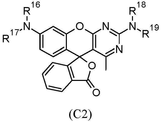
- useful d) one or more color-forming compounds can be represented by one or more of the following Structure (C1) and Structure (C2): wherein R 11 through R 19 are independently hydrogen, unsubstituted or substituted alkyl groups, or unsubstituted or substituted aryl groups.
- Such substituted or unsubstituted alkyl groups can have 1 to 20 carbon atoms, and possibly one or more substituents can include but are not limited to halogen, alkyl, aryl, alkoxy, and phenoxy groups.
- Useful substituted or unsubstituted aryl groups can be carbocyclic aromatic rings or heterocyclic aromatic rings, and such groups can have two or more fused rings.
- Useful substituents for the aryl rings can include but are not limited to, those described above for the alkyl groups.
- skilled chemists could design other useful d) color-forming compounds using this teaching about Structures (C1) and (C2) as guidance.
- mixtures of two or more of such d) color-forming compounds can be present if desired, in any desired molar ratio.
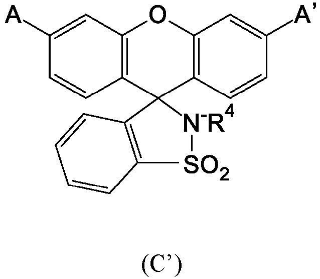
- At least one of the d) color-forming compounds present in the infrared radiation-sensitive image-recording layer is not a compound represented by the following Structure (C'): wherein A and A' are the same or different group represented by the following Structure (AA'): R 4 is an unsubstituted alkyl group for example having 1 to 6 carbon atoms, R 5 is an unsubstituted alkyl group for example having 1 to 6 carbon atoms, and R 6 is a halogen or an alkyl sulfonyl group for example having 1 to 6 carbon atoms.
- Structure (C') Compounds that fall within Structure (C') are described for example in EP 2,018,3b5B1 (Nguyen et al. ).
- At least one of the d) one or more color-forming compounds is not a compound represented by one of the following Structures (X) and (Y):
- the infrared radiation-sensitive image-recording layer also includes e) one or more compounds, each of which is represented by the following Structure (P): wherein:
- R 1 is hydrogen or a substituted or unsubstituted alkyl group, generally having from 1 to 20 carbon atoms in the unsubstituted form.
- the alkyl group can have one or more substituents as allowed by its valence, as long as such substituents do not adversely affect the function of the d) printout composition in providing a suitable, stable printout image as defined herein.
- R 2 and R 3 are independently a chloro, thioalkyl (having 1 or 2 carbon atoms), or acetyl, group.
- m and n are independently 0 or an integer of from 1 to 4. Typically, m and n are independently 0, 1, or 2. Each of m and n can be zero; m can be zero and n can be 1 or 2; or m can be 1 and n can be 1 or 2.
- the total amount of the d) one or more color-forming compounds in the infrared radiation-sensitive image-recording layer is generally at least 1 weight %, or at least 2 weight %, and up to and including 8 weight % or up to and including 10 weight % (generic maximum), all based on the total dry coverage of the infrared radiation-sensitive image-recording layer.
- the e) one or more compounds, each represented by Structure (P) can be present in an amount that suitably effects optimal printout image and stability of that printout image.
- the molar ratio of d) one or more color-forming compounds to e) one or more compounds represented by Structure (P) can be at least 1.1:1.0 and up to and including 50:1.0, or more likely at least 1.1:1.0 and up to and including 30:1.0.
- the infrared radiation-sensitive image-recording layer further comprise a f) non-free radically polymerizable polymeric material (or polymeric binder) that does not have any functional groups that, if present, would make the polymeric material capable of free radical polymerization.
- f) non-free radically polymerizable polymeric materials are different from the a) one or more free radically polymerizable components described above, and they are different materials from all of the b), c), d), and e) components described above.
- non-free radically polymerizable polymeric materials can be selected from polymeric binder materials known in the art including polymers comprising recurring units having side chains comprising polyalkylene oxide segments such as those described in for example, U.S. Patent 6,899,994 (Huang et al. ).
- Other useful polymeric binders comprise two or more types of recurring units having different side chains comprising polyalkylene oxide segments as described in for example WO Publication 2015-156065 (Kamiya et al. ).
- Some of such polymeric binders can further comprise recurring units having pendant cyano groups as those described in for example U.S. Patent 7,261,998 (Hayashi et al. ).
- Such f) polymeric binders also can have a backbone comprising multiple (at least two) urethane moieties as well as pendant groups comprising the polyalkylenes oxide segments.
- Some useful f) non-free radically polymerizable polymeric materials can be present in particulate form, that is, in the form of discrete particles (non-agglomerated particles).
- Such discrete particles can have an average particle size of at least 10 nm and up to and including 1500 nm, or typically of at least 80 nm and up to and including 600 nm, and that are generally distributed uniformly within the infrared radiation-sensitive image-recoding layer.
- Some of these materials can be present in particulate form and have an average particle size of at least 50 nm and up to and including 400 nm.
- Average particle size can be determined using various known methods and nanoparticle measuring equipment, including measuring the particles in electron scanning microscope images and averaging a set number of measurements.
- the f) non-free radically polymerizable polymeric material can be present in the form of particles having an average particle size that is less than the average dry thickness (t) of the infrared radiation-sensitive image-recording layer.
- the f) non-free radically polymerizable polymeric material(s) can be present in an amount of at least 10 weight %, or at least 20 weight %, and up to and including 50 weight %, or up to and including 70 weight %, based on the total dry coverage of the infrared radiation-sensitive image-recording layer.
- Useful f) non-free radically polymerizable polymeric materials generally have a weight average molecular weight (M w ) of at least 2,000, or at least 20,000, and up to and including 300,000 or up to and including 500,000, as determined by Gel Permeation Chromatography (polystyrene standard).
- Useful f) non-free radically polymerizable polymeric materials can be obtained from various commercial sources or they can be prepared using known procedures and starting materials, as described for example in publications described above.
- the infrared radiation-sensitive image-recording layer can include crosslinked polymer particles as additional optional addenda, such materials having an average particle size of at least 2 ⁇ m, or of at least 4 ⁇ m, and up to and including 20 ⁇ m as described for example in U.S. Patents 9,366,962 (Hayakawa et al. ), 8,383,319 (Huang et al. ) and 8,105,751 (Endo et al ).
- Such crosslinked polymeric particles can be present only in the infrared radiation-sensitive image-recording layer, the hydrophilic protective layer when present (described below), or in both the infrared radiation-sensitive image-recording layer and the hydrophilic protective layer when present.
- the infrared radiation-sensitive image-recording layer can also include a variety of other optional addenda including but not limited to, dispersing agents, humectants, biocides, plasticizers, surfactants for coatability or other properties, viscosity builders, pH adjusters, drying agents, defoamers, development aids, rheology modifiers, or combinations thereof, or any other addenda commonly used in the lithographic art, in conventional amounts.
- the infrared radiation-sensitive image-recording layer can also include a phosphate (meth)acrylate having a molecular weight generally greater than 250 as described in U.S. Patent 7,429,445 (Munnelly et al. ).
- the infrared radiation-sensitive image-recording layer is the outermost layer with no layers disposed thereon, it is possible that the precursors according to this invention can be designed with a hydrophilic protective layer (also known in the art as a hydrophilic overcoat, oxygen-barrier layer, or topcoat) disposed directly on the single infrared radiation-sensitive image-recording layer (with no intermediate layers between these two layers).
- a hydrophilic protective layer also known in the art as a hydrophilic overcoat, oxygen-barrier layer, or topcoat
- this hydrophilic protective layer is generally the outermost layer of the precursor and thus, when multiple precursors are stacked one on top of the other, the hydrophilic protective layer of one precursor can be in contact with the backside of the substrate of the precursor immediately above it, where no interleaving paper is present.
- Such hydrophilic protective layers can comprise one or more film-forming water-soluble polymeric binders in an amount of at least 60 weight % and up to and including 100 weight %, based on the total dry weight of the hydrophilic protective layer.
- film-forming water-soluble (or hydrophilic) polymeric binders can include a modified or unmodified poly(vinyl alcohol) having a saponification degree of at least 30%, or a degree of at least 75%, or a degree of at least 90%, and a degree of up to and including 99.9%.
- one or more acid-modified poly(vinyl alcohol)s can be used as film-forming water-soluble (or hydrophilic) polymeric binders in the hydrophilic protective layer.
- at least one poly(vinyl alcohol) can be modified with an acid group selected from the group consisting of carboxylic acid, sulfonic acid, sulfuric acid ester, phosphonic acid, and phosphoric acid ester groups.
- useful modified poly(vinyl alcohol) materials include but are not limited to, sulfonic acid-modified poly(vinyl alcohol), carboxylic acid-modified poly(vinyl alcohol), and quaternary ammonium salt-modified poly(vinyl alcohol), glycol-modified poly(vinyl alcohol), or combinations thereof.
- the optional hydrophilic overcoat can also include crosslinked polymer particles having an average particle size of at least 2 ⁇ m and as noted above.
- the hydrophilic protective layer is provided as a hydrophilic protective layer formation and dried to provide a dry coating coverage of at least 0.1 g/m 2 and up to but less than 4 g/m 2 , and typically at a dry coating coverage of at least 0.15 g/m 2 and up to and including 2.5 g/m 2 .
- the dry coating coverage is as low as 0.1 g/m 2 and up to and including 1.5 g/m 2 or at least 0.1 g/m 2 and up to and including 0.9 g/m 2 , such that the hydrophilic protective layer is relatively thin for easy removal during off-press development or on-press development.
- the hydrophilic protective layer can optionally comprise organic wax particles dispersed, generally uniformly, within the one or more film-forming water-soluble (or hydrophilic) polymeric binders as described for example in U.S. Patent Application Publication 2013/0323643 (Balbinot et al. ).
- An infrared radiation-sensitive image-recording layer formulation comprising components a), b), c), d), and e), and optionally f), described above can be applied to a hydrophilic surface of a suitable aluminum-containing substrate, usually in the form of a continuous web, as described above using any suitable equipment and procedure, such as spin coating, knife coating, gravure coating, die coating, slot coating, bar coating, wire rod coating, roller coating, or extrusion hopper coating.
- Such formulation can also be applied by spraying onto a suitable substrate.
- the infrared radiation-sensitive image-recording layer formulation is applied at a suitable wet coverage, it is dried in a suitable manner known in the art to provide a desired dry coverage as noted below, thereby providing an infrared radiation-sensitive continuous web or an infrared radiation-sensitive continuous article.
- the aluminum-containing substrate that is, a continuous roll or web
- the aluminum-containing substrate has been electrochemically grained and anodized as described above to provide a suitable hydrophilic anodic (aluminum oxide) layer on the outer surface of the aluminum-containing support, and the anodized surface usually can be post-treated with a hydrophilic polymer solution as described above.
- the conditions and results of these operations are well known in the art as described above.
- the manufacturing methods typically include mixing the various components needed for the infrared radiation-sensitive image-recording layer in a suitable organic solvent or mixtures thereof with or without water [such as methyl ethyl ketone (2-butanone), methanol, ethanol, 1-methoxy-2-propanol, 2-methoxypropanol, iso -propyl alcohol, acetone, ⁇ -butyrolactone, n -propanol, tetrahydrofuran, and others readily known in the art, as well as mixtures thereof], applying the resulting infrared radiation-sensitive image-recording layer formulation to a continuous substrate web, and removing the solvent(s) by evaporation under suitable drying conditions.
- a suitable organic solvent or mixtures thereof such as methyl ethyl ketone (2-butanone), methanol, ethanol, 1-methoxy-2-propanol, 2-methoxypropanol, iso -propyl alcohol, acetone, ⁇
- the dry coverage of the infrared radiation-sensitive image-recording layer on the aluminum-containing substrate is generally at least 0.1 g/m 2 , or at least 0.4 g/m 2 , and up to and including 2 g/m 2 or up to and including 4 g/m 2 but other dry coverage amounts can be used if desired.
- a suitable aqueous-based hydrophilic protective layer formulation (described above) can be applied to the dried infrared radiation-sensitive image-recording layer using known coating and drying conditions, equipment, and procedures.
- the result of these coating operations is a continuous radiation-sensitive web (or roll) of infrared radiation-sensitive lithographic printing plate precursor material having either only a single infrared radiation-sensitive image-recording layer or both a single infrared radiation-sensitive image-recording layer and a hydrophilic protective layer disposed as the outermost layer.
- an infrared radiation-sensitive lithographic printing plate precursor of this invention can be exposed to a suitable source of exposing infrared radiation depending upon the infrared radiation absorber(s) present in the infrared radiation-sensitive image-recording layer.
- the lithographic printing plate precursors can be imaged with one or more lasers that emit significant infrared radiation within the range of at least 750 nm and up to and including 1400 nm, or of at least 800 nm and up to and including 1250 nm to create exposed regions and non-exposed regions in the infrared radiation-sensitive image-recording layer.
- Such infrared radiation-emitting lasers can be used for such imaging in response to digital information supplied by a computing device or other source of digital information.
- the laser imaging can be digitally controlled in a suitable manner known in the art.
- imaging can be carried out using imaging or exposing infrared radiation from an infrared radiation-generating laser (or array of such lasers). Imaging also can be carried out using imaging radiation at multiple infrared (or near-IR) wavelengths at the same time if desired.
- the laser(s) used to expose the precursor is usually a diode laser(s), because of the reliability and low maintenance of diode laser systems, but other lasers such as gas or solid-state lasers can also be used.
- the combination of power, intensity and exposure time for infrared radiation imaging would be readily apparent to one skilled in the art.
- the infrared imaging apparatus can be configured as a flatbed recorder or as a drum recorder, with the infrared radiation-sensitive lithographic printing plate precursor mounted to the interior or exterior cylindrical surface of the drum.
- An example of useful imaging apparatus is available as models of KODAK ® Trendsetter platesetters (Eastman Kodak Company) and NEC AMZISetter X-series (NEC Corporation, Japan) that contain laser diodes that emit radiation at a wavelength of about 830 nm.
- Other suitable imaging apparatus includes the Screen PlateRite 4300 series or 8600 series platesetters (available from Screen USA, Chicago, IL) or thermal CTP platesetters from Panasonic Corporation (Japan) that operates at a wavelength of 810 nm.
- imaging intensities can be at least 30 mJ/cm 2 and up to and including 500 mJ/cm 2 and typically at least 50 mJ/cm 2 and up to and including 300 mJ/cm 2 depending upon the sensitivity of the infrared radiation-sensitive image-recording layer.
- the exposed infrared radiation-sensitive lithographic printing plate precursors having exposed regions and non-exposed regions in the infrared radiation-sensitive image-recording layer can be processed off-press or on-press to remove the non-exposed regions (and any hydrophilic protective layer over such regions).
- the revealed hydrophilic substrate surface repels inks while the remaining exposed regions accept lithographic printing ink.
- Processing can be carried out off-press using any suitable developer in one or more successive applications (treatments or developing steps) of the same or different processing solution (developer). Such one or more successive processing treatments can be carried out for a time sufficient to remove the non-exposed regions of the infrared radiation-sensitive image-recording layer to reveal the outermost hydrophilic surface of the inventive substrate, but not long enough to remove significant amounts of the exposed regions that have been hardened in the same layer.
- the exposed precursors Prior to such off-press processing, the exposed precursors can be subjected to a "pre-heating" process to further harden the exposed regions in the infrared radiation-sensitive image-recording layer.
- pre-heating can be carried out using any known process and equipment generally at a temperature of at least 60°C and up to and including 180°C.
- the exposed precursor can be washed (rinsed) to remove any hydrophilic overcoat that is present.
- washing can be carried out using any suitable aqueous solution (such as water or an aqueous solution of a surfactant) at a suitable temperature and for a suitable time that would be readily apparent to one skilled in the art.
- Useful developers can be ordinary water or formulated aqueous solutions.
- the formulated developers can comprise one or more components selected from surfactants, organic solvents, alkali agents, and surface protective agents.
- useful organic solvents include the reaction products of phenol with ethylene oxide and propylene oxide [such as ethylene glycol phenyl ether (phenoxyethanol)], benzyl alcohol, esters of ethylene glycol and of propylene glycol with acids having 6 or less carbon atoms, and ethers of ethylene glycol, diethylene glycol, and of propylene glycol with alkyl groups having 6 or less carbon atoms, such as 2-ethylethanol and 2-butoxyethanol.
- an aqueous processing solution can be used off-press to both develop the imaged precursor by removing the non-exposed regions and also to provide a protective layer or coating over the entire imaged and developed (processed) precursor printing surface.
- the aqueous solution behaves somewhat like a gum that is capable of protecting (or "gumming") the lithographic image on the lithographic printing plate against contamination or damage (for example, from oxidation, fingerprints, dust, or scratches).
- the resulting lithographic printing plate can be mounted onto a printing press without any contact with additional solutions or liquids. It is optional to further bake the lithographic printing plate with or without blanket or flood-wise exposure to UV or visible radiation.
- Printing can be carried out by applying a lithographic printing ink and fountain solution to the printing surface of the lithographic printing plate in a suitable manner.
- the fountain solution is taken up by the hydrophilic surface of the inventive substrate revealed by the exposing and processing steps, and the lithographic ink is taken up by the remaining (exposed) regions of the infrared radiation-sensitive image-recording layer.
- the lithographic ink is then transferred to a suitable receiving material (such as cloth, paper, metal, glass, or plastic) to provide a desired impression of the image thereon.
- a suitable receiving material such as cloth, paper, metal, glass, or plastic
- an intermediate "blanket” roller can be used to transfer the lithographic ink from the lithographic printing plate to the receiving material (for example, sheets of paper).
- the negative-working lithographic printing plate precursors of the present invention are on-press developable using a lithographic printing ink, a fountain solution, or a combination of a lithographic printing ink and a fountain solution.
- an imaged (exposed) infrared radiation-sensitive lithographic printing plate precursor according to the present invention is mounted onto a printing press and the printing operation is begun.
- the non-exposed regions in the infrared radiation-sensitive image-recording layer are removed by a suitable fountain solution, lithographic printing ink, or a combination of both, when the initial printed impressions are made.
- Typical ingredients of aqueous fountain solutions include pH buffers, desensitizing agents, surfactants and wetting agents, humectants, low boiling solvents, biocides, antifoaming agents, and sequestering agents.
- a representative example of a fountain solution is Varn Litho Etch 142W + Varn PAR (alcohol sub) (available from Varn International, Addison, IL).
- the dampening roller is engaged first and supplies fountain solution to the mounted imaged precursor to swell the exposed infrared radiation-sensitive image-recording layer at least in the non-exposed regions.
- the inking rollers are engaged and they supply lithographic printing ink(s) to cover the entire printing surface of the lithographic printing plates.
- printing sheets are supplied to remove the non-exposed regions of the infrared radiation-sensitive image-recording layer from the lithographic printing plate as well as materials on a blanket cylinder if present, using the formed ink-fountain solution emulsion.
- On-press developability of infrared radiation exposed lithographic printing precursors is particularly useful when the precursor comprises one or more polymeric binder materials (whether free radically polymerizable or not) in an infrared radiation-sensitive image-recording layer, at least one of which polymeric binders is present as particles having an average diameter of at least 50 nm and up to and including 400 nm.
- An aluminum-containing substrate was prepared for the lithographic printing plate precursors in the following manner: A surface of an aluminum alloy sheet (support) was subjected to an electrolytic roughening treatment using hydrochloric acid to provide an average roughness Ra of 0.5 ⁇ m. The resulting grained aluminum sheet was subjected to an anodizing treatment using an aqueous phosphoric acid solution to form an aluminum oxide layer of about 500 nm in dry thickness, followed by a post-treatment application of a poly(acrylic acid) solution, to provide an aluminum-containing substrate.
- An infrared radiation-sensitive image recording layer was then applied to the aluminum-containing substrate by coating the infrared radiation-sensitive recording layer formulation having the components shown in the following TABLE I using a bar coater, to provide a dry coating weight of 0.9 g/m 2 after drying at 50°C for 60 seconds, and components and their amounts are defined below in TABLE II and TABLE III.
- the "examples” are identified as either comparative examples (C-1 through C-15) or inventive examples (1-1 through 1-4).
- Each of the lithographic printing plate precursors was imagewise exposed using a Trendsetter 800 III Quantum TH 1.7 (available from Eastman Kodak Company) at 120 mJ/cm 2 to provide exposed regions and non-exposed regions in the IR-sensitive recording layer.
- the color difference between exposed regions and non-exposed regions was measured by determining the ⁇ E value, using a Techkon Spectro Dens spectral densitometer, calculating the Euclidean distance of the measured L*a*b values, and given the following qualitative values.
- Each lithographic printing plate precursor was imagewise exposed as described above, and then placed in a light sealed box with a D50 white light source attached in a way that 1000 Lux was measured at the position of the lithographic printing plate precursors.
- the white light was turned on for exactly one hour.
- On-press developability was evaluated by imagewise exposing each lithographic printing plate precursor at 120 mJ/cm 2 using a Trendsetter 800 III Quantum TH 1.7 (available from Eastman Kodak Company). Each imagewise exposed lithographic printing plate precursor was then mounted onto a MAN Roland Favorite 04 press machine without developing (processing). Fountain solution (Varn Supreme 6038) and lithographic printing ink (Gans Cyan) were supplied, and lithographic printing was performed. On-press development occurred during printing. Acceptable on-press developability was observed with a clean background within 15 sheets.
Landscapes
- Physics & Mathematics (AREA)
- Optics & Photonics (AREA)
- Thermal Sciences (AREA)
- Engineering & Computer Science (AREA)
- Manufacturing & Machinery (AREA)
- Materials For Photolithography (AREA)
- Printing Plates And Materials Therefor (AREA)
- Manufacture Or Reproduction Of Printing Formes (AREA)
- Photosensitive Polymer And Photoresist Processing (AREA)
Claims (15)
- Ein Lithographiedruckplattenvorläufer, umfassend ein aluminiumhaltiges Substrat, und eine infrarotstrahlungsempfindliche Bildaufzeichnungsschicht, angeordnet auf dem aluminiumhaltiges Substrat,
wobei die infrarotstrahlungsempfindliche Bildaufzeichnungsschicht umfasst:a) ein oder mehrere radikalisch polymerisierbare Komponenten;b) ein oder mehrere Infrarotstrahlungsabsorber;c) ein Initiatorzusammensetzung;d) ein oder mehrere farbbildende Verbindungen;e) ein oder mehrere Verbindungen, jeweils dargestellt durch die folgende Struktur (P): f) gegebenenfalls ein nicht radikalisch polymerisierbares Polymermaterial, das sich von den oben definierten Komponenten a), b), c), d) und e) unterscheidet,wobei die infrarotstrahlungsempfindliche Bildaufzeichnungsschicht durch Belichtung mit Infrarotstrahlung, um belichtete Bereiche und nicht belichtete Bereiche bereitzustellen, einen Farbkontrast zwischen den belichteten Bereichen und den nicht belichteten Bereichen von ΔE größer als 8 aufweist und wobei ein ΔE von mindestens 5 zwischen den belichteten Bereichen und den nicht belichteten Bereichen nach Lagerung der belichteten Bildaufzeichnungsschicht unter weißem Licht für mindestens eine Stunde beibehalten wird.
 - Der Lithographiedruckplattenvorläufer nach Anspruch 1, mit der Maßgabe, dass mindestens eine der d) ein oder mehreren farbbildenden Verbindungen keine Verbindung ist, die durch die folgende Struktur (C') dargestellt wird:

- Der Lithographiedruckplattenvorläufer nach Anspruch 1 oder 2, mit der Maßgabe, dass mindestens eine der d) ein oder mehreren farbbildenden Verbindungen keine Verbindung ist, die durch eine der folgenden Strukturen (X) und (Y) dargestellt wird:


- Der Lithographiedruckplattenvorläufer nach einem der Ansprüche 1 bis 3, wobei mindestens eine der d) ein oder mehreren farbbildenden Verbindungen eine Lacton-Unterstruktur umfasst.
- Der Lithographiedruckplattenvorläufer nach einem der Ansprüche 1 bis 4, wobei die d) ein oder mehreren farbbildenden Verbindungen und die e) ein oder mehreren Verbindungen, dargestellt durch die Struktur (P), in der infrarotstrahlungsempfindlichen Bildaufzeichnungsschicht in einem Molverhältnis von d) zu e) von mindestens 1,1:1 bis einschließlich 50:1 vorhanden sind.
- Der Lithographiedruckplattenvorläufer nach Anspruch 5, wobei die d) ein oder mehreren farbbildenden Verbindungen in der infrarotstrahlungsempfindlichen Bildaufzeichnungsschicht in einer Trockenbedeckungsmenge von mindestens 2 Gew.-% und bis zu und einschließlich 10 Gew.-% vorhanden sind.
- Der Lithographiedruckplattenvorläufer nach einem der Ansprüche 1 bis 6, wobei die a) ein oder mehreren radikalisch polymerisierbaren Komponenten mindestens zwei radikalisch polymerisierbare Komponenten umfassen.
- Der Lithographiedruckplattenvorläufer nach einem der Ansprüche 1 bis 7, wobei die c) Initiatorzusammensetzung ein Diaryliodoniumsalz umfasst.
- Der Lithographiedruckplattenvorläufer nach einem der Ansprüche 1 bis 8, wobei X gleich -S- ist.
- Der Lithographiedruckplattenvorläufer nach einem der Ansprüche 1 bis 9, wobei m und n unabhängig 0, 1 oder 2 sind und R2 und R3 unabhängig ein Chlor, ein Thioalkyl mit 1 oder 2 Kohlenstoffatomen oder eine Acetylgruppe sind.
- Der Lithographiedruckplattenvorläufer nach einem der Ansprüche 1 bis 10, wobei die d) ein oder mehreren farbbildenden Verbindungen durch eine oder beide der folgenden Strukturen (C1) und (C2) dargestellt werden:

- Der Lithographiedruckplattenvorläufer nach einem der Ansprüche 1 bis 11, wobei die e) ein oder mehreren Verbindungen, dargestellt durch die Struktur (P), eine oder mehrere der folgenden Verbindungen 1 bis 4 sind:
1 
2 
3 
4 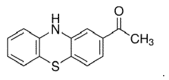
- Der Lithographiedruckplattenvorläufer nach einem der Ansprüche 1 bis 12, wobei die c) Initiatorzusammensetzung ein Tetraarylborat umfasst.
- Ein Verfahren zur Bereitstellung einer Lithographiedruckplatte, umfassend:A) bildweises Belichten des Lithographiedruckplattenvorläufers nach einem der Ansprüche 1 bis 13 mit Infrarotstrahlung, um belichtete Bereiche und nicht belichtete Bereiche in der infrarotstrahlungsempfindlichen Bildaufzeichnungsschicht bereitzustellen, undB) Entfernen der nicht belichteten Bereiche in der infrarotstrahlungsempfindlichen Bildaufzeichnungsschicht von dem aluminiumhaltigen Substrat.
- Das Verfahren nach Anspruch 14, umfassend das Entfernen der nicht belichteten Bereiche in der infrarotstrahlungsempfindlichen Bildaufzeichnungsschicht von dem aluminiumhaltigen Substrat on-press unter Verwendung einer lithographischen Druckfarbe, eines Feuchtmittels oder einer Kombination aus einer lithographischen Druckfarbe und eines Feuchtmittels.
Applications Claiming Priority (2)
| Application Number | Priority Date | Filing Date | Title |
|---|---|---|---|
| US16/572,731 US20210078350A1 (en) | 2019-09-17 | 2019-09-17 | Lithographic printing plate precursor and method of use |
| PCT/US2020/049793 WO2021055187A1 (en) | 2019-09-17 | 2020-09-09 | Lithographic printing plate precursor and method of use |
Publications (2)
| Publication Number | Publication Date |
|---|---|
| EP4031375A1 EP4031375A1 (de) | 2022-07-27 |
| EP4031375B1 true EP4031375B1 (de) | 2025-02-12 |
Family
ID=72659324
Family Applications (1)
| Application Number | Title | Priority Date | Filing Date |
|---|---|---|---|
| EP20780821.3A Active EP4031375B1 (de) | 2019-09-17 | 2020-09-09 | Lithografischer druckplattenvorläufer und verfahren zur verwendung |
Country Status (5)
| Country | Link |
|---|---|
| US (1) | US20210078350A1 (de) |
| EP (1) | EP4031375B1 (de) |
| JP (1) | JP2022547714A (de) |
| CN (1) | CN114423613B (de) |
| WO (1) | WO2021055187A1 (de) |
Families Citing this family (9)
| Publication number | Priority date | Publication date | Assignee | Title |
|---|---|---|---|---|
| WO2022212032A1 (en) | 2021-04-01 | 2022-10-06 | Eastman Kodak Company | Lithographic printing plate precursor and method of use |
| US12436459B2 (en) | 2021-04-01 | 2025-10-07 | Eastman Kodak Company | Lithographic printing plate precursor and method of use |
| US20230091079A1 (en) | 2021-07-23 | 2023-03-23 | Eastman Kodak Company | Lithographic printing plate precursor and method of use |
| US12222645B2 (en) | 2022-03-03 | 2025-02-11 | Eastman Kodak Company | Lithographic printing plate precursor and method of use |
| US12429774B2 (en) | 2022-08-04 | 2025-09-30 | Eastman Kodak Company | Lithographic printing plate precursors, methods of using and manufacture |
| US20240069439A1 (en) | 2022-08-12 | 2024-02-29 | Eastman Kodak Company | Lithographic printing plate precursor and method of use |
| JP2024143725A (ja) | 2023-03-30 | 2024-10-11 | 富士フイルム株式会社 | 機上現像型平版印刷版原版、平版印刷版の作製方法、及び、平版印刷方法 |
| JP2024143724A (ja) | 2023-03-30 | 2024-10-11 | 富士フイルム株式会社 | 機上現像型平版印刷版原版、平版印刷版の作製方法、平版印刷方法、及び化合物 |
| US12429770B2 (en) | 2023-06-27 | 2025-09-30 | Eastman Kodak Company | Lithographic printing plate precursor and method of use |
Family Cites Families (52)
| Publication number | Priority date | Publication date | Assignee | Title |
|---|---|---|---|---|
| DE3312497A1 (de) | 1983-04-07 | 1984-10-11 | Hoechst Ag, 6230 Frankfurt | Zweistufiges verfahren zur herstellung von anodisch oxidierten flaechigen materialien aus aluminium und deren verwendung bei der herstellung von offsetdruckplatten |
| GB9004337D0 (en) | 1990-02-27 | 1990-04-25 | Minnesota Mining & Mfg | Preparation and use of dyes |
| US6153356A (en) | 1998-08-17 | 2000-11-28 | Mitsubishi Chemical Corporation | Photopolymerizable composition, photopolymerizable lithographic printing plate and process for forming an image |
| JP3654422B2 (ja) | 2000-01-31 | 2005-06-02 | 三菱製紙株式会社 | 感光性組成物および感光性平版印刷版材料 |
| US6309792B1 (en) | 2000-02-18 | 2001-10-30 | Kodak Polychrome Graphics Llc | IR-sensitive composition and use thereof for the preparation of printing plate precursors |
| EP1182033B1 (de) | 2000-08-21 | 2006-11-22 | Fuji Photo Film Co., Ltd. | Bildaufzeichnungsmaterial |
| JP2002082429A (ja) | 2000-09-08 | 2002-03-22 | Fuji Photo Film Co Ltd | ネガ型画像記録材料 |
| JP4319363B2 (ja) | 2001-01-15 | 2009-08-26 | 富士フイルム株式会社 | ネガ型画像記録材料 |
| US7261998B2 (en) | 2001-04-04 | 2007-08-28 | Eastman Kodak Company | Imageable element with solvent-resistant polymeric binder |
| US6899994B2 (en) | 2001-04-04 | 2005-05-31 | Kodak Polychrome Graphics Llc | On-press developable IR sensitive printing plates using binder resins having polyethylene oxide segments |
| US6893797B2 (en) | 2001-11-09 | 2005-05-17 | Kodak Polychrome Graphics Llc | High speed negative-working thermal printing plates |
| US7368215B2 (en) | 2003-05-12 | 2008-05-06 | Eastman Kodak Company | On-press developable IR sensitive printing plates containing an onium salt initiator system |
| JP2005035162A (ja) * | 2003-07-14 | 2005-02-10 | Fuji Photo Film Co Ltd | 平版印刷版の製版方法、平版印刷方法および機上現像用平版印刷原版 |
| US7018775B2 (en) | 2003-12-15 | 2006-03-28 | Eastman Kodak Company | Infrared absorbing N-alkylsulfate cyanine compounds |
| EP1717024A1 (de) | 2004-01-23 | 2006-11-02 | Fuji Photo Film Co., Ltd. | Flachdruckplattenvorläufer und Flachdruckverfahren. |
| JP2005306000A (ja) * | 2004-01-23 | 2005-11-04 | Fuji Photo Film Co Ltd | 平版印刷版原版及び平版印刷方法 |
| JP2006062188A (ja) * | 2004-08-26 | 2006-03-09 | Fuji Photo Film Co Ltd | 色画像形成材料及び平版印刷版原版 |
| US7189494B2 (en) | 2005-05-26 | 2007-03-13 | Eastman Kodak Company | On-press developable imageable element comprising a tetraarylborate salt |
| JP5170960B2 (ja) | 2005-08-29 | 2013-03-27 | 富士フイルム株式会社 | 平版印刷版原版、及び平版印刷方法 |
| US7955682B2 (en) | 2006-04-25 | 2011-06-07 | Hewlett-Packard Development Company, L.P. | Photochemical and photothermal rearrangements for optical data and image recording |
| EP2018365B1 (de) | 2006-05-17 | 2014-11-19 | American Dye Source, Inc. | Neue materialien für die beschichtung lithographischer platten, lithographische platten und beschichtungen, die diese enthalten, herstellungsverfahren und verwendung |
| US7524614B2 (en) | 2006-05-26 | 2009-04-28 | Eastman Kodak Company | Negative-working radiation-sensitive compositions and imageable materials |
| US8105751B2 (en) | 2006-06-09 | 2012-01-31 | Fujifilm Corporation | Planographic printing plate precursor and pile of planographic printing plate precursors |
| US7429445B1 (en) | 2007-03-07 | 2008-09-30 | Eastman Kodak Company | Negative-working imageable elements and methods of use |
| JP4887192B2 (ja) * | 2007-03-22 | 2012-02-29 | 富士フイルム株式会社 | 平版印刷版原版及び平版印刷方法 |
| US20090047599A1 (en) | 2007-08-15 | 2009-02-19 | Geoffrey Horne | Negative-working imageable elements and methods of use |
| US7858292B2 (en) | 2007-12-04 | 2010-12-28 | Eastman Kodak Company | Imageable elements with components having 1H-tetrazole groups |
| EP2098367A1 (de) | 2008-03-05 | 2009-09-09 | Eastman Kodak Company | Sensibilisator/Initiator-Kombination für negativ arbeitende wärmeempfindliche Zusammensetzungen für Lithografieplatten |
| JP5189448B2 (ja) * | 2008-09-26 | 2013-04-24 | 富士フイルム株式会社 | 平版印刷版原版及び平版印刷版の製版方法 |
| US8383319B2 (en) | 2009-08-25 | 2013-02-26 | Eastman Kodak Company | Lithographic printing plate precursors and stacks |
| US8329383B2 (en) * | 2009-11-05 | 2012-12-11 | Eastman Kodak Company | Negative-working lithographic printing plate precursors |
| US8783179B2 (en) | 2009-12-28 | 2014-07-22 | Fujifilm Corporation | Support for planographic printing plate, method for producing support for planographic printing plate, and planographic printing original plate |
| JP5498403B2 (ja) | 2010-01-29 | 2014-05-21 | 富士フイルム株式会社 | 平版印刷版用支持体、平版印刷版用支持体の製造方法、および平版印刷版原版 |
| JP5612531B2 (ja) | 2010-04-30 | 2014-10-22 | 富士フイルム株式会社 | 平版印刷版用支持体、および平版印刷版原版 |
| CN102616049B (zh) | 2011-01-31 | 2015-04-01 | 富士胶片株式会社 | 平版印刷版载体和预制感光版 |
| US8722308B2 (en) | 2011-08-31 | 2014-05-13 | Eastman Kodak Company | Aluminum substrates and lithographic printing plate precursors |
| US8632941B2 (en) | 2011-09-22 | 2014-01-21 | Eastman Kodak Company | Negative-working lithographic printing plate precursors with IR dyes |
| US20130101938A1 (en) * | 2011-10-20 | 2013-04-25 | Koji Hayashi | On-press developable lithographic printing plate precursors |
| EP2808173A4 (de) | 2012-01-24 | 2015-07-01 | Fujifilm Corp | Träger für eine lithographie-druckplatte, verfahren zur herstellung des trägers für eine lithographie-druckplatte und master für die lithographie-druckplatte |
| US8679726B2 (en) | 2012-05-29 | 2014-03-25 | Eastman Kodak Company | Negative-working lithographic printing plate precursors |
| EP2735903B1 (de) | 2012-11-22 | 2019-02-27 | Eastman Kodak Company | Negativ arbeitende Lithografiedruckplattenvorläufer mit hochverzweigtem Bindemittelmaterial |
| US9221290B2 (en) * | 2013-12-06 | 2015-12-29 | Toshiba Tec Kabushiki Kaisha | Apparatus and method for forming an image with a plurality of decolorizable materials and for decolorizing the image |
| JP6271594B2 (ja) * | 2014-01-31 | 2018-01-31 | 富士フイルム株式会社 | 赤外線感光性発色組成物、平版印刷版原版、平版印刷版の製版方法、及び、赤外線感光性発色剤 |
| JP2015202586A (ja) | 2014-04-11 | 2015-11-16 | イーストマン コダック カンパニー | 平版印刷版原版 |
| US9366962B1 (en) | 2015-03-10 | 2016-06-14 | Eastman Kodak Company | Negative-working lithographic printing plate precursor and use |
| US20170217149A1 (en) | 2016-01-28 | 2017-08-03 | Eastman Kodak Company | Negatively-working lithographic printing plate precursor and method |
| WO2017141882A1 (ja) | 2016-02-19 | 2017-08-24 | 富士フイルム株式会社 | 発色組成物、平版印刷版原版、平版印刷版の作製方法、及び発色性化合物 |
| EP3566099B1 (de) * | 2017-01-04 | 2021-02-24 | Eastman Kodak Company | Negativ arbeitender lithographie-druckplattenvorläufer und verwendung |
| US10828884B2 (en) | 2017-03-02 | 2020-11-10 | Eastman Kodak Company | Lithographic printing plate precursors and method of use |
| US10576730B2 (en) | 2017-07-19 | 2020-03-03 | Eastman Kodak Company | Method for preparing lithographic printing plates |
| EP3660588B1 (de) * | 2017-07-25 | 2021-08-25 | FUJIFILM Corporation | Lithographiedruckplattenvorläufer, verfahren zur herstellung einer lithographiedruckplatte und farbentwickelnde zusammensetzung |
| US20200096865A1 (en) | 2018-09-21 | 2020-03-26 | Eastman Kodak Company | Lithographic printing plate precursor and color-forming composition |
-
2019
- 2019-09-17 US US16/572,731 patent/US20210078350A1/en not_active Abandoned
-
2020
- 2020-09-09 JP JP2022516359A patent/JP2022547714A/ja active Pending
- 2020-09-09 WO PCT/US2020/049793 patent/WO2021055187A1/en not_active Ceased
- 2020-09-09 EP EP20780821.3A patent/EP4031375B1/de active Active
- 2020-09-09 CN CN202080065238.6A patent/CN114423613B/zh active Active
Also Published As
| Publication number | Publication date |
|---|---|
| CN114423613B (zh) | 2023-04-21 |
| CN114423613A (zh) | 2022-04-29 |
| EP4031375A1 (de) | 2022-07-27 |
| JP2022547714A (ja) | 2022-11-15 |
| US20210078350A1 (en) | 2021-03-18 |
| WO2021055187A1 (en) | 2021-03-25 |
Similar Documents
| Publication | Publication Date | Title |
|---|---|---|
| EP4031375B1 (de) | Lithografischer druckplattenvorläufer und verfahren zur verwendung | |
| EP3408098B1 (de) | Negativ arbeitender lithographiedruckplattenvorläufer und verfahren | |
| EP3853026B1 (de) | Flachdruckplattenvorläufer und farbbildende zusammensetzung | |
| EP4126548B1 (de) | Lithographiedruckplattenvorläufer und verfahren zur herstellung einer lithographischen druckplatte | |
| EP2920648B1 (de) | Negativ arbeitender lithografiedruckplattenvorläufer | |
| EP3566099B1 (de) | Negativ arbeitender lithographie-druckplattenvorläufer und verwendung | |
| US12222645B2 (en) | Lithographic printing plate precursor and method of use | |
| WO2010033182A1 (en) | On-press developable imageable elements | |
| US12436459B2 (en) | Lithographic printing plate precursor and method of use | |
| EP4373674B1 (de) | Lithographiedruckplattenvorläufer und verfahren zur bereitstellung einer lithographiedruckplatte | |
| US20240069439A1 (en) | Lithographic printing plate precursor and method of use | |
| EP4208344B1 (de) | Lithographiedruckplattenvorläufer und verfahren zur verwendung | |
| US20220324220A1 (en) | Lithographic printing plate precursor and method of use | |
| US20250123560A1 (en) | Lithographic printing plate precursor and method of use | |
| EP4301600A1 (de) | Lithographiedruckplattenvorläufer und verfahren zur verwendung | |
| WO2022212032A1 (en) | Lithographic printing plate precursor and method of use |
Legal Events
| Date | Code | Title | Description |
|---|---|---|---|
| STAA | Information on the status of an ep patent application or granted ep patent |
Free format text: STATUS: UNKNOWN |
|
| STAA | Information on the status of an ep patent application or granted ep patent |
Free format text: STATUS: THE INTERNATIONAL PUBLICATION HAS BEEN MADE |
|
| PUAI | Public reference made under article 153(3) epc to a published international application that has entered the european phase |
Free format text: ORIGINAL CODE: 0009012 |
|
| STAA | Information on the status of an ep patent application or granted ep patent |
Free format text: STATUS: REQUEST FOR EXAMINATION WAS MADE |
|
| 17P | Request for examination filed |
Effective date: 20220322 |
|
| AK | Designated contracting states |
Kind code of ref document: A1 Designated state(s): AL AT BE BG CH CY CZ DE DK EE ES FI FR GB GR HR HU IE IS IT LI LT LU LV MC MK MT NL NO PL PT RO RS SE SI SK SM TR |
|
| DAV | Request for validation of the european patent (deleted) | ||
| DAX | Request for extension of the european patent (deleted) | ||
| STAA | Information on the status of an ep patent application or granted ep patent |
Free format text: STATUS: EXAMINATION IS IN PROGRESS |
|
| 17Q | First examination report despatched |
Effective date: 20231025 |
|
| GRAP | Despatch of communication of intention to grant a patent |
Free format text: ORIGINAL CODE: EPIDOSNIGR1 |
|
| STAA | Information on the status of an ep patent application or granted ep patent |
Free format text: STATUS: GRANT OF PATENT IS INTENDED |
|
| INTG | Intention to grant announced |
Effective date: 20241017 |
|
| GRAS | Grant fee paid |
Free format text: ORIGINAL CODE: EPIDOSNIGR3 |
|
| GRAA | (expected) grant |
Free format text: ORIGINAL CODE: 0009210 |
|
| STAA | Information on the status of an ep patent application or granted ep patent |
Free format text: STATUS: THE PATENT HAS BEEN GRANTED |
|
| AK | Designated contracting states |
Kind code of ref document: B1 Designated state(s): AL AT BE BG CH CY CZ DE DK EE ES FI FR GB GR HR HU IE IS IT LI LT LU LV MC MK MT NL NO PL PT RO RS SE SI SK SM TR |
|
| P01 | Opt-out of the competence of the unified patent court (upc) registered |
Free format text: CASE NUMBER: APP_497/2025 Effective date: 20250107 |
|
| REG | Reference to a national code |
Ref country code: GB Ref legal event code: FG4D |
|
| REG | Reference to a national code |
Ref country code: CH Ref legal event code: EP |
|
| REG | Reference to a national code |
Ref country code: DE Ref legal event code: R096 Ref document number: 602020045966 Country of ref document: DE |
|
| REG | Reference to a national code |
Ref country code: IE Ref legal event code: FG4D |
|
| REG | Reference to a national code |
Ref country code: NL Ref legal event code: MP Effective date: 20250212 |
|
| PG25 | Lapsed in a contracting state [announced via postgrant information from national office to epo] |
Ref country code: RS Free format text: LAPSE BECAUSE OF FAILURE TO SUBMIT A TRANSLATION OF THE DESCRIPTION OR TO PAY THE FEE WITHIN THE PRESCRIBED TIME-LIMIT Effective date: 20250512 |
|
| PG25 | Lapsed in a contracting state [announced via postgrant information from national office to epo] |
Ref country code: FI Free format text: LAPSE BECAUSE OF FAILURE TO SUBMIT A TRANSLATION OF THE DESCRIPTION OR TO PAY THE FEE WITHIN THE PRESCRIBED TIME-LIMIT Effective date: 20250212 |
|
| PG25 | Lapsed in a contracting state [announced via postgrant information from national office to epo] |
Ref country code: PL Free format text: LAPSE BECAUSE OF FAILURE TO SUBMIT A TRANSLATION OF THE DESCRIPTION OR TO PAY THE FEE WITHIN THE PRESCRIBED TIME-LIMIT Effective date: 20250212 |
|
| PG25 | Lapsed in a contracting state [announced via postgrant information from national office to epo] |
Ref country code: ES Free format text: LAPSE BECAUSE OF FAILURE TO SUBMIT A TRANSLATION OF THE DESCRIPTION OR TO PAY THE FEE WITHIN THE PRESCRIBED TIME-LIMIT Effective date: 20250212 |
|
| REG | Reference to a national code |
Ref country code: LT Ref legal event code: MG9D |
|
| PG25 | Lapsed in a contracting state [announced via postgrant information from national office to epo] |
Ref country code: IS Free format text: LAPSE BECAUSE OF FAILURE TO SUBMIT A TRANSLATION OF THE DESCRIPTION OR TO PAY THE FEE WITHIN THE PRESCRIBED TIME-LIMIT Effective date: 20250612 Ref country code: NO Free format text: LAPSE BECAUSE OF FAILURE TO SUBMIT A TRANSLATION OF THE DESCRIPTION OR TO PAY THE FEE WITHIN THE PRESCRIBED TIME-LIMIT Effective date: 20250512 |
|
| PG25 | Lapsed in a contracting state [announced via postgrant information from national office to epo] |
Ref country code: NL Free format text: LAPSE BECAUSE OF FAILURE TO SUBMIT A TRANSLATION OF THE DESCRIPTION OR TO PAY THE FEE WITHIN THE PRESCRIBED TIME-LIMIT Effective date: 20250212 |
|
| PG25 | Lapsed in a contracting state [announced via postgrant information from national office to epo] |
Ref country code: HR Free format text: LAPSE BECAUSE OF FAILURE TO SUBMIT A TRANSLATION OF THE DESCRIPTION OR TO PAY THE FEE WITHIN THE PRESCRIBED TIME-LIMIT Effective date: 20250212 |
|
| PG25 | Lapsed in a contracting state [announced via postgrant information from national office to epo] |
Ref country code: PT Free format text: LAPSE BECAUSE OF FAILURE TO SUBMIT A TRANSLATION OF THE DESCRIPTION OR TO PAY THE FEE WITHIN THE PRESCRIBED TIME-LIMIT Effective date: 20250612 Ref country code: LV Free format text: LAPSE BECAUSE OF FAILURE TO SUBMIT A TRANSLATION OF THE DESCRIPTION OR TO PAY THE FEE WITHIN THE PRESCRIBED TIME-LIMIT Effective date: 20250212 |
|
| PG25 | Lapsed in a contracting state [announced via postgrant information from national office to epo] |
Ref country code: GR Free format text: LAPSE BECAUSE OF FAILURE TO SUBMIT A TRANSLATION OF THE DESCRIPTION OR TO PAY THE FEE WITHIN THE PRESCRIBED TIME-LIMIT Effective date: 20250513 Ref country code: BG Free format text: LAPSE BECAUSE OF FAILURE TO SUBMIT A TRANSLATION OF THE DESCRIPTION OR TO PAY THE FEE WITHIN THE PRESCRIBED TIME-LIMIT Effective date: 20250212 |
|
| REG | Reference to a national code |
Ref country code: AT Ref legal event code: MK05 Ref document number: 1765732 Country of ref document: AT Kind code of ref document: T Effective date: 20250212 |
|
| PG25 | Lapsed in a contracting state [announced via postgrant information from national office to epo] |
Ref country code: SE Free format text: LAPSE BECAUSE OF FAILURE TO SUBMIT A TRANSLATION OF THE DESCRIPTION OR TO PAY THE FEE WITHIN THE PRESCRIBED TIME-LIMIT Effective date: 20250212 |
|
| PG25 | Lapsed in a contracting state [announced via postgrant information from national office to epo] |
Ref country code: SM Free format text: LAPSE BECAUSE OF FAILURE TO SUBMIT A TRANSLATION OF THE DESCRIPTION OR TO PAY THE FEE WITHIN THE PRESCRIBED TIME-LIMIT Effective date: 20250212 |
|
| PG25 | Lapsed in a contracting state [announced via postgrant information from national office to epo] |
Ref country code: DK Free format text: LAPSE BECAUSE OF FAILURE TO SUBMIT A TRANSLATION OF THE DESCRIPTION OR TO PAY THE FEE WITHIN THE PRESCRIBED TIME-LIMIT Effective date: 20250212 |
|
| PGFP | Annual fee paid to national office [announced via postgrant information from national office to epo] |
Ref country code: DE Payment date: 20250929 Year of fee payment: 6 |
|
| PG25 | Lapsed in a contracting state [announced via postgrant information from national office to epo] |
Ref country code: IT Free format text: LAPSE BECAUSE OF FAILURE TO SUBMIT A TRANSLATION OF THE DESCRIPTION OR TO PAY THE FEE WITHIN THE PRESCRIBED TIME-LIMIT Effective date: 20250212 |
|
| PGFP | Annual fee paid to national office [announced via postgrant information from national office to epo] |
Ref country code: GB Payment date: 20250929 Year of fee payment: 6 |
|
| PG25 | Lapsed in a contracting state [announced via postgrant information from national office to epo] |
Ref country code: AT Free format text: LAPSE BECAUSE OF FAILURE TO SUBMIT A TRANSLATION OF THE DESCRIPTION OR TO PAY THE FEE WITHIN THE PRESCRIBED TIME-LIMIT Effective date: 20250212 |
|
| PGFP | Annual fee paid to national office [announced via postgrant information from national office to epo] |
Ref country code: FR Payment date: 20250925 Year of fee payment: 6 |
|
| PG25 | Lapsed in a contracting state [announced via postgrant information from national office to epo] |
Ref country code: EE Free format text: LAPSE BECAUSE OF FAILURE TO SUBMIT A TRANSLATION OF THE DESCRIPTION OR TO PAY THE FEE WITHIN THE PRESCRIBED TIME-LIMIT Effective date: 20250212 Ref country code: CZ Free format text: LAPSE BECAUSE OF FAILURE TO SUBMIT A TRANSLATION OF THE DESCRIPTION OR TO PAY THE FEE WITHIN THE PRESCRIBED TIME-LIMIT Effective date: 20250212 |
|
| PG25 | Lapsed in a contracting state [announced via postgrant information from national office to epo] |
Ref country code: RO Free format text: LAPSE BECAUSE OF FAILURE TO SUBMIT A TRANSLATION OF THE DESCRIPTION OR TO PAY THE FEE WITHIN THE PRESCRIBED TIME-LIMIT Effective date: 20250212 |
|
| PG25 | Lapsed in a contracting state [announced via postgrant information from national office to epo] |
Ref country code: SK Free format text: LAPSE BECAUSE OF FAILURE TO SUBMIT A TRANSLATION OF THE DESCRIPTION OR TO PAY THE FEE WITHIN THE PRESCRIBED TIME-LIMIT Effective date: 20250212 |
|
| REG | Reference to a national code |
Ref country code: DE Ref legal event code: R097 Ref document number: 602020045966 Country of ref document: DE |
|
| PLBE | No opposition filed within time limit |
Free format text: ORIGINAL CODE: 0009261 |
|
| STAA | Information on the status of an ep patent application or granted ep patent |
Free format text: STATUS: NO OPPOSITION FILED WITHIN TIME LIMIT |