EP4031351B1 - Systeme zur materialabscheidung - Google Patents
Systeme zur materialabscheidung Download PDFInfo
- Publication number
- EP4031351B1 EP4031351B1 EP20797189.6A EP20797189A EP4031351B1 EP 4031351 B1 EP4031351 B1 EP 4031351B1 EP 20797189 A EP20797189 A EP 20797189A EP 4031351 B1 EP4031351 B1 EP 4031351B1
- Authority
- EP
- European Patent Office
- Prior art keywords
- containers
- container
- deposition
- piston
- syringe
- Prior art date
- Legal status (The legal status is an assumption and is not a legal conclusion. Google has not performed a legal analysis and makes no representation as to the accuracy of the status listed.)
- Active
Links
Images


Classifications
-
- B—PERFORMING OPERATIONS; TRANSPORTING
- B29—WORKING OF PLASTICS; WORKING OF SUBSTANCES IN A PLASTIC STATE IN GENERAL
- B29C—SHAPING OR JOINING OF PLASTICS; SHAPING OF MATERIAL IN A PLASTIC STATE, NOT OTHERWISE PROVIDED FOR; AFTER-TREATMENT OF THE SHAPED PRODUCTS, e.g. REPAIRING
- B29C64/00—Additive manufacturing, i.e. manufacturing of three-dimensional [3D] objects by additive deposition, additive agglomeration or additive layering, e.g. by 3D printing, stereolithography or selective laser sintering
- B29C64/20—Apparatus for additive manufacturing; Details thereof or accessories therefor
- B29C64/205—Means for applying layers
- B29C64/209—Heads; Nozzles
-
- B—PERFORMING OPERATIONS; TRANSPORTING
- B29—WORKING OF PLASTICS; WORKING OF SUBSTANCES IN A PLASTIC STATE IN GENERAL
- B29C—SHAPING OR JOINING OF PLASTICS; SHAPING OF MATERIAL IN A PLASTIC STATE, NOT OTHERWISE PROVIDED FOR; AFTER-TREATMENT OF THE SHAPED PRODUCTS, e.g. REPAIRING
- B29C64/00—Additive manufacturing, i.e. manufacturing of three-dimensional [3D] objects by additive deposition, additive agglomeration or additive layering, e.g. by 3D printing, stereolithography or selective laser sintering
- B29C64/10—Processes of additive manufacturing
- B29C64/106—Processes of additive manufacturing using only liquids or viscous materials, e.g. depositing a continuous bead of viscous material
-
- B—PERFORMING OPERATIONS; TRANSPORTING
- B29—WORKING OF PLASTICS; WORKING OF SUBSTANCES IN A PLASTIC STATE IN GENERAL
- B29C—SHAPING OR JOINING OF PLASTICS; SHAPING OF MATERIAL IN A PLASTIC STATE, NOT OTHERWISE PROVIDED FOR; AFTER-TREATMENT OF THE SHAPED PRODUCTS, e.g. REPAIRING
- B29C64/00—Additive manufacturing, i.e. manufacturing of three-dimensional [3D] objects by additive deposition, additive agglomeration or additive layering, e.g. by 3D printing, stereolithography or selective laser sintering
- B29C64/20—Apparatus for additive manufacturing; Details thereof or accessories therefor
- B29C64/227—Driving means
-
- B—PERFORMING OPERATIONS; TRANSPORTING
- B33—ADDITIVE MANUFACTURING TECHNOLOGY
- B33Y—ADDITIVE MANUFACTURING, i.e. MANUFACTURING OF THREE-DIMENSIONAL [3D] OBJECTS BY ADDITIVE DEPOSITION, ADDITIVE AGGLOMERATION OR ADDITIVE LAYERING, e.g. BY 3D PRINTING, STEREOLITHOGRAPHY OR SELECTIVE LASER SINTERING
- B33Y30/00—Apparatus for additive manufacturing; Details thereof or accessories therefor
-
- B—PERFORMING OPERATIONS; TRANSPORTING
- B33—ADDITIVE MANUFACTURING TECHNOLOGY
- B33Y—ADDITIVE MANUFACTURING, i.e. MANUFACTURING OF THREE-DIMENSIONAL [3D] OBJECTS BY ADDITIVE DEPOSITION, ADDITIVE AGGLOMERATION OR ADDITIVE LAYERING, e.g. BY 3D PRINTING, STEREOLITHOGRAPHY OR SELECTIVE LASER SINTERING
- B33Y10/00—Processes of additive manufacturing
Definitions
- the present invention relates to systems for material deposition, for example, such systems as facilitate the deposition of material at a single point on a surface from several sources in rapid succession, as deposit material from a container and seal the container after deposition as part of a material printing application, and/or as seal a container holding material for deposition as part of a 3D printing application.
- certain deposition techniques such as certain methods of LIFT (laser-induced forward transfer) printing, require preparing the material to be deposited (or printed) by applying (e.g., spreading) it on a medium.
- Deposition of viscous material on the medium before spreading is often accomplished by use of compressed gas applied to the material container (e.g., by connecting a source of the gas to one opening in the container and forcing the material through a second opening and onto the medium).
- compressed gas applied to the material container (e.g., by connecting a source of the gas to one opening in the container and forcing the material through a second opening and onto the medium).
- For low viscosity materials it may be necessary to hold the materials with a vacuum and effect their deposition by releasing the vacuum or pressurizing the container with compressed gas.
- the material container In such systems, the material container must sometimes be removed from the system in order to store the material, to refrigerate it, or for other reasons. Connecting and disconnecting a gas or vacuum hose from a material container in such a manner that creates an air-tight seal while still providing for rapid connection and disconnection is challenging. Removing the seal that connects the container and the gas or vacuum hose during loading and unloading of the material container causes low-viscosity materials to leak uncontrollably out of the second opening of the container. It also exposes the contents of the container to contamination from the outside.
- CN204658952U discloses a 3D printing device including a nozzle, a DC power supply, a forming table for placing a forming substrate, a table motion control device and a receiving electrode.
- the nozzle includes a synchronously moving laser path module and at least one electrospinning module.
- the outlet axis of the laser path module and the outlet axis of the electrospinning module meet at a point.
- the electrospinning module and the receiving electrode are respectively connected to the positive and negative poles of the DC power supply, and the forming workbench is arranged between the spray head and the receiving electrode.
- the forming table is fixed on the table motion control device, and the table motion control device is used to change the distance from the forming table to the spray head.
- the invention provides according to claim 1 systems for material deposition, for example, such systems as facilitate the deposition of material at a single point on a surface from several sources in rapid succession, as deposit material from a container and seal the container after deposition as part of a material printing application, and/or as seal a container holding material for deposition as part of a 3D printing application.
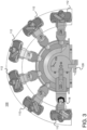
- containers such as syringes, containing material are arranged in a conical shape or other shape with all their tips pointing toward a single point of deposition.
- a piston mounted on a rotating arm is moved by a motor to the desired container.
- the piston presses down on the container holder.
- the holder slides toward the point of deposition, bringing the tip of the container into proximity with the point of deposition.
- Pressurized gas or another method is used to force material through the container.
- the piston is released, and a spring returns the container holder to its original position.
- the entire container array is mounted on a horizontal stage allowing movement in one direction or along an axis.
- a system in another embodiment, includes a plurality of containers (e.g., syringes) configured in an array to dispense material. Each if the containers has a material dispensing end and the containers are organized within the system so that each dispensing end of each container is oriented towards a common, single deposition point.
- the system further includes a piston mounted on a rotating arm. The arm is rotatable to align the piston with respective mounts of each of the containers.
- the mounts of the containers are each translatable (e.g., along respective pairs of sliders), under actuation by said piston, to a deposition position at which the containers dispense material (e.g., under the influence of a pressurized gas) and are translatable under influence of a biasing mechanism (e.g., a spring) to return to an original position at which the containers do not dispense material.
- the array of containers is mounted on a stage translatable along an axis.
- material may be deposited from respective ones of the plurality of containers towards the common, single deposition point by rotating the piston to be aligned with the mount of the respective container, actuating the piston against the mount of the respective container so as to translate the respective container (e.g., along its respective pair of sliders) to a deposition position, dispensing the material from the respective container using a pressurized gas, and translating the respective container to an original position by the biasing mechanism.
- the array of containers Prior to depositing the material, the array of containers may be translated towards the deposition point by moving a stage on which the array of containers is mounted along an axis.
- the containers are arranged with respect to one another in a cone shape, with their material dispensing ends each oriented towards the common, single deposition point.
- the sliders along with the mounts of the containers are translatable help to prevent axial rotation of the containers.
- the rotatable arm may have a slot therein and the system may further include a limit switch.
- the slot in the arm is preferably located such that when the piston is in a home position, the slot passes through the limit switch. This helps in overall aligning of the system.
- each of the containers may be received in a respective one of a plurality of holders sized to accommodate containers of different sizes.
- a rod is inserted in a material container (e.g., a syringe).
- a material container e.g., a syringe
- One end of the rod is fitted with a flexible tip which seals the hole from which the material is deposited.
- the rod and tip are forced against the hole with a pre-loaded spring or other device mounted on the opposite side of the container.
- a cylinder is attached to the opposite end of the rod. This cylinder sits inside a cylindrical tube connected to a pressurized gas supply, creating a pneumatic piston.
- the pressurized gas is used to force the piston rod away from the material exit. Simultaneously, a gap between the rod and its housing allows the gas to flow into the chamber where the material is held.
- a vacuum is applied via the pressurized gas port, e.g., sequentially after the pressurized gas, serving to return the piston and seal the exit.
- the vacuum can also be used to perform de-gassing on the material in the syringe.
- a one-way air valve is inserted in a syringe barrel adapter.
- the adapter When the adapter is connected to the syringe (the material container in this embodiment of the invention), it seals the syringe completely. This creates a vacuum in the syringe, which prevents the material from dripping out of the deposition tip uncontrollably.
- An air hose screws onto the barrel adaptor. Inside a threaded head is a small bar which presses on the one-way valve, forcing it open. On either side of the bar are holes to allow air to pass through. The air hose is easily disconnected from the top of the syringe barrel adaptor. As it is unscrewed, it ceases to press on the one-way valve, and the valve closes automatically. In this fashion syringes can easily, quickly, and cheaply be replaced to facilitate deposition of multiple materials in rapid succession.
- a flexible rubber valve replaces the one-way valve.
- the valve is forced open, pressurizing the syringe.
- the valve closes automatically, sealing the syringe.
- the one-way valve is replaced by a metal ball on a spring.
- the spring forces the ball against a rubber gasket, sealing the syringe.
- a small pin forces the ball down, opening the valve and facilitating pressurization of the syringe.
- the one-way valve is replaced by a rubber disc on a spring.
- a spring forces the rubber disc against a small aperture, sealing it shut.
- a pin presses the disc downward opening the valve.
- Described herein are systems for material deposition, for example, such systems as facilitate the deposition of material at a single point on a surface from several sources in rapid succession, as deposit material from a container and seal the container after deposition as part of a material printing application, and/or as seal a container holding material for deposition as part of a 3D printing application.
- containers such as syringes, containing material are arranged in a conical shape or other shape with all their tips pointing toward a single point of deposition.
- a piston mounted on a rotating arm is moved by a motor to the desired container.
- the piston presses down on the container holder.
- the holder slides toward the point of deposition, bringing the tip of the container into proximity with the point of deposition.
- Pressurized gas or other means is used to force material through the container.
- the piston is released, and a spring returns the container holder to its original position.
- the entire container array is mounted on a horizontal stage allowing movement in one direction or along an axis.
- each container may be fitted with a piston-like arrangement so that a respective container need only be moved to the deposition position and its respective piston (or other dispensing actuator) engaged in order to deposit material.
- Such an arrangement may provide for more rapid dispensing of material than one which requires rotation of the piston.
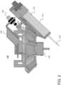
- syringes 112 containing material are arranged in a cone shape, with their tips 114 pointing at one common point in space.
- the syringes or other containers 112 can be arranged with part of their barrels 16 in a closed loop of any shape with their tips 114 pointing at a common single point in space. Springs or other biasing mechanisms keep the syringes or other containers 112 lifted a fixed distance above the deposition surface (not shown).
- each container has its own piston and there is no rotating arm.
- the container 112 slides along two sliders 126, which ensure that the container does not rotate about its axis.
- the piston 118 then brings the deposition tip 114 into proximity with the deposition surface.
- a pressurized gas or other means is then used to force material from the container 112 onto the deposition surface.
- the system can deposit material from many (six in this illustrated example, but more or fewer in other embodiments) containers in rapid succession. Because all of the containers (e.g., their point of dispensing) are close to their final location, and all that is needed is to rotate the piston into position and to actuate it, which is accomplished quickly with currently conventional pistons and motors.
- the system is equipped with a limit switch 128 to perform homing.
- the rotating arm 120 has a slot 130 cut into it.
- the slot 130 is located such that when the piston 118 is in its home position, the slot 130 passes through the limit switch 128. In this way the arm 20 can be rotated to a precise home position.
- the system is designed such that it can operate without all the containers being loaded onto the system.
- the system 100 can accommodate containers 112 of different sizes (e.g., at the same time), although this may require by leaving some container spots empty.
- each container 112 is fitted with its own dispensing mechanism (e.g., a piston like piston 118) so that when the container is brought into proximity with the deposition surface its respective dispensing mechanism can be immediately activated to dispense material.
- the dispensing mechanism e.g., a piston or other device
- the dispensing mechanism may be centrally located and bringing the container into proximity with the deposition surface would include positioning the container so that it is acted upon by the centrally located dispensing mechanism.
- the plurality of containers 112 may each include a respective piston 118 or other dispensing mechanism and may be arranged about the common point of deposition with their respective material dispensing ends 114 oriented towards that common point of deposition.
- Each container may be included within a respective mount 124 and translatable so as to actuatable by its respective piston or, alternatively by another dispensing mechanism, when in a deposition position at which each respective container dispenses material, and further translatable under influence of a biasing mechanism to return to an original position at which each respective container does not dispense material.
- the array of containers 112 may be mounted on a horizontal stage 132, which is translatable (under the control of a motor) along two rails 134a, 134b on a frame 136. This allows control over where the material is deposited in one dimension and can facilitate, for example, optimal spreading of material on a deposition surface.
- This horizontal stage 132 also gives the system the ability to remove the containers 112 from the deposition area. This facilitates maintenance tasks, cleaning containers, replacing containers, or other tasks. It also gives the system the ability to remove the containers from the working area to avoid contamination.
- a system to deposit material from many containers in rapid succession by orienting the openings of the containers toward a single point of deposition and rapidly moving the containers towards that point before deposition has been described.
- close packing of the containers in a cone or other shape with their deposition ends pointing towards the common (single) point of deposition minimizes the footprint of the system and minimizes time between deposition from each container.
- the containers are arranged so as to each move in the vertical direction (or, more generally, along a linear axis) on two sliders which prevents axial rotation of the containers.
- a system to move many containers of material for deposition along a single axis to control the point of deposition affords the ability to use containers of various sizes by using appropriately sized holders which can be removed and replaced and leaving some container slots empty, as necessary.
- a limit switch and slot cut into part of the rotating arm enables the arm to accurately return to its home position.
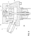
- FIG. 5-9 a system 10 and method for sealing a syringe (or other container) containing material for deposition, e.g., in a 2D or 3D printing application are illustrated.
- a rod 18 is inserted inside the syringe 26.
- a flexible cap 24 is attached to one end of the rod. This cap creates a seal with the material exit 20.
- a guide 22 can be attached to the rod 18, ensuring that the rod 18 is properly aligned with the exit 20.
- a gasket/O-ring 16 is attached to the other end of the rod 18.
- the gasket/O-ring 16 is mounted inside a cylindrical tube 36, forming a piston.
- the piston is actuated using pressurized gas. Vacuum can be used to aid operation of the piston. Gas enters via a connection 14 mounted in the syringe cap. The gas enters a channel 32 under the piston, forcing it away from the exit 20, and opening the exit. Grooves 20 in the syringe cap allow gas to enter the body of the syringe 34 where the material is held. The pressurized gas in the body of the syringe forces material through the exit 20.
- a relief hole 12 allows air to exit and enter freely according to the position of the piston.
- a vacuum can also be applied sequentially after the pressurized gas via the same port. The vacuum aids the spring 28 in returning the piston and sealing the exit 20. The vacuum can also be used to perform de-gassing on the material in the syringe.
- spring 28 forces the piston down, creating an airtight seal at the exit 20. This seal is maintained even if the syringe is disconnected from the gas/vacuum line. This allows removal of the syringe from this system without material leaking from the exit.
- the deposition of material can be controlled.
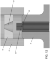
- a system 40 includes a syringe barrel adapter 46 fitted onto a syringe 48 containing the material to be deposited.
- a one-way air valve 52 is mounted inside the adapter 46.
- a gas hose 42 is attached to the end of the adapter 46 via a threaded connector 44 and is connected to a tank of pressurized air or other gas. This pressurized gas is used to force the material out of the tip of the syringe 48 when desired.
- the one-way valve 52 For the gas to flow into the syringe and pressurize it, the one-way valve 52 must be opened. This is accomplished by a small bar 50 which is part of the threaded connector 44. As the connector 44 is screwed onto the barrel adapter 46, the bar 50 presses on the one-way valve 52 forcing it open. The gas flows through the one-way valve 52 into the syringe 48 but is prevented from flowing back into the hose.
- the syringe is sealed with a flexible rubber seal instead of a one-way valve.
- the seal 56 is mounted inside the barrel adapter 46 which is inserted inside the syringe 48.
- a thin slit 55 in the top of the seal 56 can be opened to allow gas to pass through.
- the gas hose (not shown in these views) is connected to the barrel adapter 46 via a threaded connector 44.
- Mounted inside the threaded connector 44 is a cylinder 53 with a conical hole 54.
- the conical hole 54 in the cylinder 53 presses on the edges of the top of the rubber seal 56, deforming the top of the seal and forcing it open (see Figures 15A (closed) and 15B (open)).
- the top of the seal 56 has protruding sections 57 only on two sides. This ensures that when the face of the conical hole 54 meets the top of the seal 56, they will only coincide in line with the slit 55 at the top of the seal 56. This force along the length of the seal 56 will cause it to open.
- the threaded connection 44 is then screwed onto the barrel adapter 46.
- a spring 58 forces a metal ball 60 against an aperture 68 sealing the syringe 48.
- the aperture 68 is sealed by a flexible rubber gasket 62.
- the spring 58 rests inside a tube 64 which is mounted in the barrel adapter 46.
- the tube 64 is narrow enough to prevent buckling, and horizontal motion of the ball 60 as the spring 58 is compressed.
- the tube 64 is also wide enough to ensure the passage of gas when the valve is open.
- This valve is connected to the gas hose by a threaded connector 44. Inside this connector 44 is mounted a metal sleeve 66 with a pin 67 suspended inside.
- the sleeve 66 has spaces for gas to pass from the hose to the valve/syringe, and the pin 67 is centered in line with the ball 60.
- the pin 67 presses on the ball 60 compressing the spring (see Figure 18 ). This opens the valve allowing gas to flow through.
- the one-way valve is replaced with a flexible rubber disc 70 attached to a spring 58.
- the spring 58 forces the disc 70 against a hole in a tube 72 mounted inside the barrel adapter 46.
- the disc 70 is mounted on the end of a rod 74 which rests inside the spring 58, preventing the spring from buckling and the disc from deflecting away from the hole.
- a sleeve 76 with a pin 77 mounted inside a threaded connection 44 which is attached to the end of the gas hose. When the hose is connected the pin 77 presses down on the disc 70 (see Figure 60), opening the seal, and allowing gas to pass into the syringe.
- a sealing system for a container of a materials deposition system used in a 3D printing process allows a seal to close automatically when the container is disconnected from a gas hose or vacuum.
- a one-way valve is inserted within a syringe barrel adapter that attaches to the syringe, the syringe serving as the materials container.
- the one-way valve is replaced with a rubber seal that remains closed unless forced open by pressure from a conical hole inside a cylindrical part.
- a further embodiment replaces the one-way valve with a metal ball on a spring, which presses against an aperture sealing the syringe until forced open by the action of connecting the syringe to a gas hose.
- Another embodiment operates in a similar way, replacing the ball with a rubber seal.
- the materials container is sealed off from the environment preventing contamination of a material in the container from the outside.
- the invention allows for simple replacement of the container because the container itself is sealed.
- the connection to the air hose or vacuum does not have to be overly tight and can therefore be detached easily.
Landscapes
- Chemical & Material Sciences (AREA)
- Engineering & Computer Science (AREA)
- Materials Engineering (AREA)
- Manufacturing & Machinery (AREA)
- Physics & Mathematics (AREA)
- Mechanical Engineering (AREA)
- Optics & Photonics (AREA)
- Coating Apparatus (AREA)
Claims (9)
- System (100) für einen dreidimensionalen Drucker (3D), umfassend:
eine Mehrzahl von Behältern (112), welche in einer Anordnung konfiguriert sind, um Material abzugeben, wobei die Behälter (112) jeweils ein Materialabgabeende (114) aufweisen und wobei die Behälter (112) derart innerhalb des Systems (100) organisiert sind, dass jedes Abgabeende (114) jedes Behälters (112) in Richtung eines gemeinsamen, einzelnen Abgabepunkts orientiert ist, und wobei das System gekennzeichnet ist durch:einen Kolben (118), welcher an einem Arm (120) montiert ist, der drehbar ist, um den Kolben (116) mit Halterungen (124) jedes der Behälter (112) auszurichten, wobei die Halterungen (124) der Behälter (112) jeweils unter einer Betätigung durch den Kolben (118) zu einer Abgabeposition verschiebbar sind, an welcher die Behälter (112) Material abgeben, und unter einem Einfluss eines Vorspannmechanismus verschiebbar sind, um zu einer ursprünglichen Position zurückzukehren, an welcher die Behälter kein Material abgeben;wobei die Anordnung von Behältern (112) an einer Stufe (132) montiert ist, welche entlang einer Achse verschiebbar ist. - System nach Anspruch 1, wobei die Mehrzahl der Behälter (112) in einer Kegelform angeordnet sind, wobei deren Materialabgabeenden (114) jeweils in Richtung des gemeinsamen, einzelnen Abscheidungspunkts orientiert sind.
- System nach einem der vorhergehenden Ansprüche, wobei die Halterungen (124) der Behälter (112) unter einer Betätigung des Kolbens (116) entlang jeweiliger Paare von Gleitstücken (126) verschiebbar sind.
- System nach einem der vorhergehenden Ansprüche, wobei die Behälter (112) Spritzen umfassen.
- System nach einem der vorhergehenden Ansprüche, wobei der Arm (120) darin einen Schlitz (130) aufweist und das System (100) ferner einen Begrenzungsschalter (128) umfasst, wobei der Schlitz (130) in dem Arm (120) derart angeordnet ist, dass, wenn sich der Kolben (118) in einer Ausgangsposition befindet, der Schlitz (130) durch den Begrenzungsschalter (128) passt.
- System nach einem der vorhergehenden Ansprüche, wobei jeder der Behälter (112) in einem jeweiligen einer Mehrzahl von Haltern aufgenommen ist, wobei die Halter bemessen sind, um Behälter (112) verschiedener Größen unterzubringen.
- Dreidimensionales (3D) Druckverfahren, umfassend:
Abscheiden von Material aus einer Mehrzahl von Behältern (112) eines Systems (100) in Richtung eines gemeinsamen, einzelnen Abscheidungspunkts, wobei jeder Behälter (112) ein Element einer Anordnung ist und ein Materialabgabeende (114) aufweist und die Mehrzahl von Behältern derart innerhalb des Systems organisiert ist, dass jedes Abgabeende (114) jedes Behälters (112) in Richtung des gemeinsamen, einzelnen Abscheidungspunkts orientiert ist, und wobei das Verfahren dadurch gekennzeichnet ist, dass:
das Abscheiden von jedem jeweiligen Behälter (112) der Mehrzahl von Behältern umfasst:Drehen eines Kolbens (118) derart, dass er mit einer Halterung (124) des jeweiligen Behälters (112) ausgerichtet ist,Betätigen des Kolbens (118) gegen die Halterung (124) des jeweiligen Behälters (112), um den jeweiligen Behälter (112) zu einer Abscheidungsposition zu verschieben,Abgeben des Materials aus dem jeweiligen Behälter (112) unter Verwendung eines Druckgases undVerschieben des jeweiligen Behälters (112) zu einer ursprünglichen Position durch einen Vorspannmechanismus. - Verfahren nach Anspruch 7, wobei die Anordnung von Behältern an einer Stufe (132) montiert ist, welche entlang einer Achse verschiebbar ist, und wobei das Verfahren ein Verschieben der Stufe (132) umfasst, um die Behälter in Richtung des Abscheidungspunkts zu bewegen, bevor eine Materialabscheidung beginnt.
- Verfahren nach Anspruch 7 oder 8, wobei das Betätigen des Kolbens (118) gegen die Halterung (124) des jeweiligen Behälters (112), um den jeweiligen Behälter (112) zu einer Abscheidungsposition zu verschieben, ein Verschieben des jeweiligen Behälters (112) entlang eines Paars von Gleitstücken (126) zu der Abscheidungsposition umfasst.
Applications Claiming Priority (3)
| Application Number | Priority Date | Filing Date | Title |
|---|---|---|---|
| US201962930920P | 2019-11-05 | 2019-11-05 | |
| US201962931013P | 2019-11-05 | 2019-11-05 | |
| PCT/IB2020/059665 WO2021090089A1 (en) | 2019-11-05 | 2020-10-14 | Systems for material deposition |
Publications (3)
| Publication Number | Publication Date |
|---|---|
| EP4031351A1 EP4031351A1 (de) | 2022-07-27 |
| EP4031351C0 EP4031351C0 (de) | 2024-01-03 |
| EP4031351B1 true EP4031351B1 (de) | 2024-01-03 |
Family
ID=73014554
Family Applications (1)
| Application Number | Title | Priority Date | Filing Date |
|---|---|---|---|
| EP20797189.6A Active EP4031351B1 (de) | 2019-11-05 | 2020-10-14 | Systeme zur materialabscheidung |
Country Status (3)
| Country | Link |
|---|---|
| US (2) | US11285667B2 (de) |
| EP (1) | EP4031351B1 (de) |
| WO (1) | WO2021090089A1 (de) |
Families Citing this family (2)
| Publication number | Priority date | Publication date | Assignee | Title |
|---|---|---|---|---|
| DE102021117285A1 (de) * | 2021-07-05 | 2023-01-05 | Grob-Werke Gmbh & Co. Kg | Vorrichtung zur additiven fertigung eines bauteils |
| GB2623067A (en) * | 2022-09-30 | 2024-04-10 | Orbital Matter Ug | 3D printing apparatus |
Citations (1)
| Publication number | Priority date | Publication date | Assignee | Title |
|---|---|---|---|---|
| US20180243478A1 (en) * | 2015-09-04 | 2018-08-30 | The General Hospital Corporation | Three dimensional microtissue bioprinter |
Family Cites Families (3)
| Publication number | Priority date | Publication date | Assignee | Title |
|---|---|---|---|---|
| CN204658952U (zh) | 2015-03-16 | 2015-09-23 | 东莞劲胜精密组件股份有限公司 | 一种3d打印装置 |
| US10259158B2 (en) * | 2016-04-15 | 2019-04-16 | The Curators Of The University Of Missouri | Method and apparatus for fabricating ceramic and metal components via additive manufacturing with uniform layered radiation drying |
| US11203151B2 (en) | 2017-04-04 | 2021-12-21 | 3D Systems, Inc. | Multi-headed auto-calibrating bioprinter with heads that heat, cool, and crosslink |
-
2020
- 2020-10-14 EP EP20797189.6A patent/EP4031351B1/de active Active
- 2020-10-14 US US16/949,113 patent/US11285667B2/en active Active
- 2020-10-14 WO PCT/IB2020/059665 patent/WO2021090089A1/en not_active Ceased
-
2021
- 2021-12-06 US US17/457,724 patent/US11858211B2/en active Active
Patent Citations (1)
| Publication number | Priority date | Publication date | Assignee | Title |
|---|---|---|---|---|
| US20180243478A1 (en) * | 2015-09-04 | 2018-08-30 | The General Hospital Corporation | Three dimensional microtissue bioprinter |
Also Published As
| Publication number | Publication date |
|---|---|
| EP4031351C0 (de) | 2024-01-03 |
| US20210129433A1 (en) | 2021-05-06 |
| US20220088863A1 (en) | 2022-03-24 |
| WO2021090089A1 (en) | 2021-05-14 |
| US11858211B2 (en) | 2024-01-02 |
| US11285667B2 (en) | 2022-03-29 |
| EP4031351A1 (de) | 2022-07-27 |
Similar Documents
| Publication | Publication Date | Title |
|---|---|---|
| US11858211B2 (en) | Systems for material deposition | |
| EP2300198B1 (de) | Vorrichtung zum blocken von werkstücken, insbesondere brillengläsern, für deren bearbeitung und/oder beschichtung | |
| US5435462A (en) | Liquid cartridge storage case for use with liquid dipenser | |
| US4095722A (en) | Dripless dispenser and method of dispensing a flowable material | |
| DE69231358T2 (de) | System zum austragen eines mediums | |
| KR20220122483A (ko) | 캐니스터 충전 시스템을 위한 어댑터 및 가스 캐니스터를 충전하는 방법 | |
| CA2940182C (en) | Application apparatus | |
| US20060283523A1 (en) | Method and apparatus for the storage and preservation of liquids compounds | |
| US6308868B1 (en) | High pressure cartridge feed system | |
| KR20190007536A (ko) | 잉크젯 인쇄 시스템용 인쇄 헤드 유닛 조립체 | |
| EP0414031A1 (de) | Verfahren und Vorrichtung zum Füllen von Behältern | |
| EP1418050B1 (de) | Vorrichtung zum Zuführen von vorverpackter Farbe zum Farbkasten von Druckmaschinen | |
| EP2750895B1 (de) | Vorrichtung zum behandeln von packmitteln sowie drucksegment zur verwendung bei einer solchen vorrichtung | |
| DE2352029A1 (de) | Abgabevorrichtung fuer thermoplastisches material | |
| EP4063025A1 (de) | Endeffektor mit positiver verdrängung mit mehreren kartuschen | |
| CN111533065B (zh) | 用于处理容器的装置 | |
| EP3646955B1 (de) | Vorrichtungen und verfahren zur abgabe fliessfähiger materialien | |
| NZ290344A (en) | Bearing grease packer | |
| US20230339630A1 (en) | Filling apparatus | |
| JP5068942B2 (ja) | 真空ディスペンス装置 | |
| CN114867565A (zh) | 材料涂敷装置及按压构件 | |
| KR100494299B1 (ko) | 액체 토출용 디스펜서 | |
| EP2213384B1 (de) | Vorrichtung und Verfahren zum Herstellen von PET-Großgebinden | |
| CN219701856U (zh) | 加液装置 | |
| CA2687125A1 (en) | Centripetal container processing apparatus |
Legal Events
| Date | Code | Title | Description |
|---|---|---|---|
| STAA | Information on the status of an ep patent application or granted ep patent |
Free format text: STATUS: UNKNOWN |
|
| STAA | Information on the status of an ep patent application or granted ep patent |
Free format text: STATUS: THE INTERNATIONAL PUBLICATION HAS BEEN MADE |
|
| PUAI | Public reference made under article 153(3) epc to a published international application that has entered the european phase |
Free format text: ORIGINAL CODE: 0009012 |
|
| STAA | Information on the status of an ep patent application or granted ep patent |
Free format text: STATUS: REQUEST FOR EXAMINATION WAS MADE |
|
| 17P | Request for examination filed |
Effective date: 20220422 |
|
| AK | Designated contracting states |
Kind code of ref document: A1 Designated state(s): AL AT BE BG CH CY CZ DE DK EE ES FI FR GB GR HR HU IE IS IT LI LT LU LV MC MK MT NL NO PL PT RO RS SE SI SK SM TR |
|
| DAV | Request for validation of the european patent (deleted) | ||
| DAX | Request for extension of the european patent (deleted) | ||
| GRAP | Despatch of communication of intention to grant a patent |
Free format text: ORIGINAL CODE: EPIDOSNIGR1 |
|
| STAA | Information on the status of an ep patent application or granted ep patent |
Free format text: STATUS: GRANT OF PATENT IS INTENDED |
|
| INTG | Intention to grant announced |
Effective date: 20230511 |
|
| GRAS | Grant fee paid |
Free format text: ORIGINAL CODE: EPIDOSNIGR3 |
|
| GRAA | (expected) grant |
Free format text: ORIGINAL CODE: 0009210 |
|
| STAA | Information on the status of an ep patent application or granted ep patent |
Free format text: STATUS: THE PATENT HAS BEEN GRANTED |
|
| AK | Designated contracting states |
Kind code of ref document: B1 Designated state(s): AL AT BE BG CH CY CZ DE DK EE ES FI FR GB GR HR HU IE IS IT LI LT LU LV MC MK MT NL NO PL PT RO RS SE SI SK SM TR |
|
| REG | Reference to a national code |
Ref country code: GB Ref legal event code: FG4D |
|
| REG | Reference to a national code |
Ref country code: DE Ref legal event code: R096 Ref document number: 602020023905 Country of ref document: DE |
|
| REG | Reference to a national code |
Ref country code: CH Ref legal event code: EP |
|
| REG | Reference to a national code |
Ref country code: IE Ref legal event code: FG4D |
|
| U01 | Request for unitary effect filed |
Effective date: 20240110 |
|
| U07 | Unitary effect registered |
Designated state(s): AT BE BG DE DK EE FI FR IT LT LU LV MT NL PT SE SI Effective date: 20240118 |
|
| PG25 | Lapsed in a contracting state [announced via postgrant information from national office to epo] |
Ref country code: ES Free format text: LAPSE BECAUSE OF FAILURE TO SUBMIT A TRANSLATION OF THE DESCRIPTION OR TO PAY THE FEE WITHIN THE PRESCRIBED TIME-LIMIT Effective date: 20240103 |
|
| PG25 | Lapsed in a contracting state [announced via postgrant information from national office to epo] |
Ref country code: ES Free format text: LAPSE BECAUSE OF FAILURE TO SUBMIT A TRANSLATION OF THE DESCRIPTION OR TO PAY THE FEE WITHIN THE PRESCRIBED TIME-LIMIT Effective date: 20240103 |
|
| PG25 | Lapsed in a contracting state [announced via postgrant information from national office to epo] |
Ref country code: IS Free format text: LAPSE BECAUSE OF FAILURE TO SUBMIT A TRANSLATION OF THE DESCRIPTION OR TO PAY THE FEE WITHIN THE PRESCRIBED TIME-LIMIT Effective date: 20240503 |
|
| PG25 | Lapsed in a contracting state [announced via postgrant information from national office to epo] |
Ref country code: GR Free format text: LAPSE BECAUSE OF FAILURE TO SUBMIT A TRANSLATION OF THE DESCRIPTION OR TO PAY THE FEE WITHIN THE PRESCRIBED TIME-LIMIT Effective date: 20240404 |
|
| PG25 | Lapsed in a contracting state [announced via postgrant information from national office to epo] |
Ref country code: HR Free format text: LAPSE BECAUSE OF FAILURE TO SUBMIT A TRANSLATION OF THE DESCRIPTION OR TO PAY THE FEE WITHIN THE PRESCRIBED TIME-LIMIT Effective date: 20240103 Ref country code: RS Free format text: LAPSE BECAUSE OF FAILURE TO SUBMIT A TRANSLATION OF THE DESCRIPTION OR TO PAY THE FEE WITHIN THE PRESCRIBED TIME-LIMIT Effective date: 20240403 |
|
| PG25 | Lapsed in a contracting state [announced via postgrant information from national office to epo] |
Ref country code: CZ Free format text: LAPSE BECAUSE OF FAILURE TO SUBMIT A TRANSLATION OF THE DESCRIPTION OR TO PAY THE FEE WITHIN THE PRESCRIBED TIME-LIMIT Effective date: 20240103 |
|
| PG25 | Lapsed in a contracting state [announced via postgrant information from national office to epo] |
Ref country code: RS Free format text: LAPSE BECAUSE OF FAILURE TO SUBMIT A TRANSLATION OF THE DESCRIPTION OR TO PAY THE FEE WITHIN THE PRESCRIBED TIME-LIMIT Effective date: 20240403 Ref country code: NO Free format text: LAPSE BECAUSE OF FAILURE TO SUBMIT A TRANSLATION OF THE DESCRIPTION OR TO PAY THE FEE WITHIN THE PRESCRIBED TIME-LIMIT Effective date: 20240403 Ref country code: IS Free format text: LAPSE BECAUSE OF FAILURE TO SUBMIT A TRANSLATION OF THE DESCRIPTION OR TO PAY THE FEE WITHIN THE PRESCRIBED TIME-LIMIT Effective date: 20240503 Ref country code: HR Free format text: LAPSE BECAUSE OF FAILURE TO SUBMIT A TRANSLATION OF THE DESCRIPTION OR TO PAY THE FEE WITHIN THE PRESCRIBED TIME-LIMIT Effective date: 20240103 Ref country code: GR Free format text: LAPSE BECAUSE OF FAILURE TO SUBMIT A TRANSLATION OF THE DESCRIPTION OR TO PAY THE FEE WITHIN THE PRESCRIBED TIME-LIMIT Effective date: 20240404 Ref country code: CZ Free format text: LAPSE BECAUSE OF FAILURE TO SUBMIT A TRANSLATION OF THE DESCRIPTION OR TO PAY THE FEE WITHIN THE PRESCRIBED TIME-LIMIT Effective date: 20240103 |
|
| PG25 | Lapsed in a contracting state [announced via postgrant information from national office to epo] |
Ref country code: PL Free format text: LAPSE BECAUSE OF FAILURE TO SUBMIT A TRANSLATION OF THE DESCRIPTION OR TO PAY THE FEE WITHIN THE PRESCRIBED TIME-LIMIT Effective date: 20240103 |
|
| PG25 | Lapsed in a contracting state [announced via postgrant information from national office to epo] |
Ref country code: PL Free format text: LAPSE BECAUSE OF FAILURE TO SUBMIT A TRANSLATION OF THE DESCRIPTION OR TO PAY THE FEE WITHIN THE PRESCRIBED TIME-LIMIT Effective date: 20240103 |
|
| REG | Reference to a national code |
Ref country code: DE Ref legal event code: R097 Ref document number: 602020023905 Country of ref document: DE |
|
| PG25 | Lapsed in a contracting state [announced via postgrant information from national office to epo] |
Ref country code: SM Free format text: LAPSE BECAUSE OF FAILURE TO SUBMIT A TRANSLATION OF THE DESCRIPTION OR TO PAY THE FEE WITHIN THE PRESCRIBED TIME-LIMIT Effective date: 20240103 |
|
| PG25 | Lapsed in a contracting state [announced via postgrant information from national office to epo] |
Ref country code: SK Free format text: LAPSE BECAUSE OF FAILURE TO SUBMIT A TRANSLATION OF THE DESCRIPTION OR TO PAY THE FEE WITHIN THE PRESCRIBED TIME-LIMIT Effective date: 20240103 |
|
| PG25 | Lapsed in a contracting state [announced via postgrant information from national office to epo] |
Ref country code: SM Free format text: LAPSE BECAUSE OF FAILURE TO SUBMIT A TRANSLATION OF THE DESCRIPTION OR TO PAY THE FEE WITHIN THE PRESCRIBED TIME-LIMIT Effective date: 20240103 Ref country code: SK Free format text: LAPSE BECAUSE OF FAILURE TO SUBMIT A TRANSLATION OF THE DESCRIPTION OR TO PAY THE FEE WITHIN THE PRESCRIBED TIME-LIMIT Effective date: 20240103 Ref country code: RO Free format text: LAPSE BECAUSE OF FAILURE TO SUBMIT A TRANSLATION OF THE DESCRIPTION OR TO PAY THE FEE WITHIN THE PRESCRIBED TIME-LIMIT Effective date: 20240103 |
|
| PLBE | No opposition filed within time limit |
Free format text: ORIGINAL CODE: 0009261 |
|
| STAA | Information on the status of an ep patent application or granted ep patent |
Free format text: STATUS: NO OPPOSITION FILED WITHIN TIME LIMIT |
|
| U20 | Renewal fee for the european patent with unitary effect paid |
Year of fee payment: 5 Effective date: 20241028 |
|
| 26N | No opposition filed |
Effective date: 20241007 |
|
| REG | Reference to a national code |
Ref country code: CH Ref legal event code: PL |
|
| GBPC | Gb: european patent ceased through non-payment of renewal fee |
Effective date: 20241014 |
|
| PG25 | Lapsed in a contracting state [announced via postgrant information from national office to epo] |
Ref country code: MC Free format text: LAPSE BECAUSE OF FAILURE TO SUBMIT A TRANSLATION OF THE DESCRIPTION OR TO PAY THE FEE WITHIN THE PRESCRIBED TIME-LIMIT Effective date: 20240103 |
|
| PG25 | Lapsed in a contracting state [announced via postgrant information from national office to epo] |
Ref country code: GB Free format text: LAPSE BECAUSE OF NON-PAYMENT OF DUE FEES Effective date: 20241014 |
|
| PG25 | Lapsed in a contracting state [announced via postgrant information from national office to epo] |
Ref country code: CH Free format text: LAPSE BECAUSE OF NON-PAYMENT OF DUE FEES Effective date: 20241031 |
|
| PG25 | Lapsed in a contracting state [announced via postgrant information from national office to epo] |
Ref country code: IE Free format text: LAPSE BECAUSE OF NON-PAYMENT OF DUE FEES Effective date: 20241014 |
|
| U20 | Renewal fee for the european patent with unitary effect paid |
Year of fee payment: 6 Effective date: 20251027 |
|
| PG25 | Lapsed in a contracting state [announced via postgrant information from national office to epo] |
Ref country code: CY Free format text: LAPSE BECAUSE OF FAILURE TO SUBMIT A TRANSLATION OF THE DESCRIPTION OR TO PAY THE FEE WITHIN THE PRESCRIBED TIME-LIMIT; INVALID AB INITIO Effective date: 20201014 |
|
| PG25 | Lapsed in a contracting state [announced via postgrant information from national office to epo] |
Ref country code: HU Free format text: LAPSE BECAUSE OF FAILURE TO SUBMIT A TRANSLATION OF THE DESCRIPTION OR TO PAY THE FEE WITHIN THE PRESCRIBED TIME-LIMIT; INVALID AB INITIO Effective date: 20201014 |