EP4031343B1 - Verfahren zur herstellung einer mikrofluidischen architektur - Google Patents
Verfahren zur herstellung einer mikrofluidischen architektur Download PDFInfo
- Publication number
- EP4031343B1 EP4031343B1 EP20780302.4A EP20780302A EP4031343B1 EP 4031343 B1 EP4031343 B1 EP 4031343B1 EP 20780302 A EP20780302 A EP 20780302A EP 4031343 B1 EP4031343 B1 EP 4031343B1
- Authority
- EP
- European Patent Office
- Prior art keywords
- layer
- architecture
- channel
- support material
- layers
- Prior art date
- Legal status (The legal status is an assumption and is not a legal conclusion. Google has not performed a legal analysis and makes no representation as to the accuracy of the status listed.)
- Active
Links
Images




Classifications
-
- B—PERFORMING OPERATIONS; TRANSPORTING
- B01—PHYSICAL OR CHEMICAL PROCESSES OR APPARATUS IN GENERAL
- B01L—CHEMICAL OR PHYSICAL LABORATORY APPARATUS FOR GENERAL USE
- B01L3/00—Containers or dishes for laboratory use, e.g. laboratory glassware; Droppers
- B01L3/50—Containers for the purpose of retaining a material to be analysed, e.g. test tubes
- B01L3/502—Containers for the purpose of retaining a material to be analysed, e.g. test tubes with fluid transport, e.g. in multi-compartment structures
- B01L3/5027—Containers for the purpose of retaining a material to be analysed, e.g. test tubes with fluid transport, e.g. in multi-compartment structures by integrated microfluidic structures, i.e. dimensions of channels and chambers are such that surface tension forces are important, e.g. lab-on-a-chip
- B01L3/502707—Containers for the purpose of retaining a material to be analysed, e.g. test tubes with fluid transport, e.g. in multi-compartment structures by integrated microfluidic structures, i.e. dimensions of channels and chambers are such that surface tension forces are important, e.g. lab-on-a-chip characterised by the manufacture of the container or its components
-
- B—PERFORMING OPERATIONS; TRANSPORTING
- B29—WORKING OF PLASTICS; WORKING OF SUBSTANCES IN A PLASTIC STATE IN GENERAL
- B29C—SHAPING OR JOINING OF PLASTICS; SHAPING OF MATERIAL IN A PLASTIC STATE, NOT OTHERWISE PROVIDED FOR; AFTER-TREATMENT OF THE SHAPED PRODUCTS, e.g. REPAIRING
- B29C39/00—Shaping by casting, i.e. introducing the moulding material into a mould or between confining surfaces without significant moulding pressure; Apparatus therefor
- B29C39/02—Shaping by casting, i.e. introducing the moulding material into a mould or between confining surfaces without significant moulding pressure; Apparatus therefor for making articles of definite length, i.e. discrete articles
- B29C39/12—Making multilayered or multicoloured articles
- B29C39/123—Making multilayered articles
-
- A—HUMAN NECESSITIES
- A61—MEDICAL OR VETERINARY SCIENCE; HYGIENE
- A61F—FILTERS IMPLANTABLE INTO BLOOD VESSELS; PROSTHESES; DEVICES PROVIDING PATENCY TO, OR PREVENTING COLLAPSING OF, TUBULAR STRUCTURES OF THE BODY, e.g. STENTS; ORTHOPAEDIC, NURSING OR CONTRACEPTIVE DEVICES; FOMENTATION; TREATMENT OR PROTECTION OF EYES OR EARS; BANDAGES, DRESSINGS OR ABSORBENT PADS; FIRST-AID KITS
- A61F2/00—Filters implantable into blood vessels; Prostheses, i.e. artificial substitutes or replacements for parts of the body; Appliances for connecting them with the body; Devices providing patency to, or preventing collapsing of, tubular structures of the body, e.g. stents
- A61F2/50—Prostheses not implantable in the body
- A61F2/78—Means for protecting prostheses or for attaching them to the body, e.g. bandages, harnesses, straps, or stockings for the limb stump
- A61F2/7812—Interface cushioning members placed between the limb stump and the socket, e.g. bandages or stockings for the limb stump
-
- B—PERFORMING OPERATIONS; TRANSPORTING
- B01—PHYSICAL OR CHEMICAL PROCESSES OR APPARATUS IN GENERAL
- B01L—CHEMICAL OR PHYSICAL LABORATORY APPARATUS FOR GENERAL USE
- B01L3/00—Containers or dishes for laboratory use, e.g. laboratory glassware; Droppers
-
- B—PERFORMING OPERATIONS; TRANSPORTING
- B29—WORKING OF PLASTICS; WORKING OF SUBSTANCES IN A PLASTIC STATE IN GENERAL
- B29C—SHAPING OR JOINING OF PLASTICS; SHAPING OF MATERIAL IN A PLASTIC STATE, NOT OTHERWISE PROVIDED FOR; AFTER-TREATMENT OF THE SHAPED PRODUCTS, e.g. REPAIRING
- B29C33/00—Moulds or cores; Details thereof or accessories therefor
-
- B—PERFORMING OPERATIONS; TRANSPORTING
- B29—WORKING OF PLASTICS; WORKING OF SUBSTANCES IN A PLASTIC STATE IN GENERAL
- B29C—SHAPING OR JOINING OF PLASTICS; SHAPING OF MATERIAL IN A PLASTIC STATE, NOT OTHERWISE PROVIDED FOR; AFTER-TREATMENT OF THE SHAPED PRODUCTS, e.g. REPAIRING
- B29C33/00—Moulds or cores; Details thereof or accessories therefor
- B29C33/0033—Moulds or cores; Details thereof or accessories therefor constructed for making articles provided with holes
-
- B—PERFORMING OPERATIONS; TRANSPORTING
- B29—WORKING OF PLASTICS; WORKING OF SUBSTANCES IN A PLASTIC STATE IN GENERAL
- B29C—SHAPING OR JOINING OF PLASTICS; SHAPING OF MATERIAL IN A PLASTIC STATE, NOT OTHERWISE PROVIDED FOR; AFTER-TREATMENT OF THE SHAPED PRODUCTS, e.g. REPAIRING
- B29C33/00—Moulds or cores; Details thereof or accessories therefor
- B29C33/44—Moulds or cores; Details thereof or accessories therefor with means for, or specially constructed to facilitate, the removal of articles, e.g. of undercut articles
- B29C33/52—Moulds or cores; Details thereof or accessories therefor with means for, or specially constructed to facilitate, the removal of articles, e.g. of undercut articles soluble or fusible
-
- B—PERFORMING OPERATIONS; TRANSPORTING
- B29—WORKING OF PLASTICS; WORKING OF SUBSTANCES IN A PLASTIC STATE IN GENERAL
- B29C—SHAPING OR JOINING OF PLASTICS; SHAPING OF MATERIAL IN A PLASTIC STATE, NOT OTHERWISE PROVIDED FOR; AFTER-TREATMENT OF THE SHAPED PRODUCTS, e.g. REPAIRING
- B29C39/00—Shaping by casting, i.e. introducing the moulding material into a mould or between confining surfaces without significant moulding pressure; Apparatus therefor
- B29C39/02—Shaping by casting, i.e. introducing the moulding material into a mould or between confining surfaces without significant moulding pressure; Apparatus therefor for making articles of definite length, i.e. discrete articles
-
- B—PERFORMING OPERATIONS; TRANSPORTING
- B29—WORKING OF PLASTICS; WORKING OF SUBSTANCES IN A PLASTIC STATE IN GENERAL
- B29C—SHAPING OR JOINING OF PLASTICS; SHAPING OF MATERIAL IN A PLASTIC STATE, NOT OTHERWISE PROVIDED FOR; AFTER-TREATMENT OF THE SHAPED PRODUCTS, e.g. REPAIRING
- B29C39/00—Shaping by casting, i.e. introducing the moulding material into a mould or between confining surfaces without significant moulding pressure; Apparatus therefor
- B29C39/22—Component parts, details or accessories; Auxiliary operations
- B29C39/26—Moulds or cores
-
- B—PERFORMING OPERATIONS; TRANSPORTING
- B29—WORKING OF PLASTICS; WORKING OF SUBSTANCES IN A PLASTIC STATE IN GENERAL
- B29C—SHAPING OR JOINING OF PLASTICS; SHAPING OF MATERIAL IN A PLASTIC STATE, NOT OTHERWISE PROVIDED FOR; AFTER-TREATMENT OF THE SHAPED PRODUCTS, e.g. REPAIRING
- B29C39/00—Shaping by casting, i.e. introducing the moulding material into a mould or between confining surfaces without significant moulding pressure; Apparatus therefor
- B29C39/22—Component parts, details or accessories; Auxiliary operations
- B29C39/26—Moulds or cores
- B29C39/34—Moulds or cores for undercut articles
-
- B—PERFORMING OPERATIONS; TRANSPORTING
- B81—MICROSTRUCTURAL TECHNOLOGY
- B81B—MICROSTRUCTURAL DEVICES OR SYSTEMS, e.g. MICROMECHANICAL DEVICES
- B81B1/00—Devices without movable or flexible elements, e.g. microcapillary devices
- B81B1/002—Holes characterised by their shape, in either longitudinal or sectional plane
-
- B—PERFORMING OPERATIONS; TRANSPORTING
- B81—MICROSTRUCTURAL TECHNOLOGY
- B81C—PROCESSES OR APPARATUS SPECIALLY ADAPTED FOR THE MANUFACTURE OR TREATMENT OF MICROSTRUCTURAL DEVICES OR SYSTEMS
- B81C99/00—Subject matter not provided for in other groups of this subclass
-
- B—PERFORMING OPERATIONS; TRANSPORTING
- B81—MICROSTRUCTURAL TECHNOLOGY
- B81C—PROCESSES OR APPARATUS SPECIALLY ADAPTED FOR THE MANUFACTURE OR TREATMENT OF MICROSTRUCTURAL DEVICES OR SYSTEMS
- B81C99/00—Subject matter not provided for in other groups of this subclass
- B81C99/0075—Manufacture of substrate-free structures
- B81C99/0085—Manufacture of substrate-free structures using moulds and master templates, e.g. for hot-embossing
-
- A—HUMAN NECESSITIES
- A61—MEDICAL OR VETERINARY SCIENCE; HYGIENE
- A61F—FILTERS IMPLANTABLE INTO BLOOD VESSELS; PROSTHESES; DEVICES PROVIDING PATENCY TO, OR PREVENTING COLLAPSING OF, TUBULAR STRUCTURES OF THE BODY, e.g. STENTS; ORTHOPAEDIC, NURSING OR CONTRACEPTIVE DEVICES; FOMENTATION; TREATMENT OR PROTECTION OF EYES OR EARS; BANDAGES, DRESSINGS OR ABSORBENT PADS; FIRST-AID KITS
- A61F2/00—Filters implantable into blood vessels; Prostheses, i.e. artificial substitutes or replacements for parts of the body; Appliances for connecting them with the body; Devices providing patency to, or preventing collapsing of, tubular structures of the body, e.g. stents
- A61F2/50—Prostheses not implantable in the body
- A61F2002/501—Prostheses not implantable in the body having an inflatable pocket filled with fluid, i.e. liquid or gas
- A61F2002/5012—Prostheses not implantable in the body having an inflatable pocket filled with fluid, i.e. liquid or gas having two or more inflatable pockets
-
- A—HUMAN NECESSITIES
- A61—MEDICAL OR VETERINARY SCIENCE; HYGIENE
- A61F—FILTERS IMPLANTABLE INTO BLOOD VESSELS; PROSTHESES; DEVICES PROVIDING PATENCY TO, OR PREVENTING COLLAPSING OF, TUBULAR STRUCTURES OF THE BODY, e.g. STENTS; ORTHOPAEDIC, NURSING OR CONTRACEPTIVE DEVICES; FOMENTATION; TREATMENT OR PROTECTION OF EYES OR EARS; BANDAGES, DRESSINGS OR ABSORBENT PADS; FIRST-AID KITS
- A61F2/00—Filters implantable into blood vessels; Prostheses, i.e. artificial substitutes or replacements for parts of the body; Appliances for connecting them with the body; Devices providing patency to, or preventing collapsing of, tubular structures of the body, e.g. stents
- A61F2/50—Prostheses not implantable in the body
- A61F2/5044—Designing or manufacturing processes
- A61F2/5046—Designing or manufacturing processes for designing or making customized prostheses, e.g. using templates, finite-element analysis or CAD-CAM techniques
- A61F2002/5053—Designing or manufacturing processes for designing or making customized prostheses, e.g. using templates, finite-element analysis or CAD-CAM techniques using a positive or a negative model, e.g. casting model or mould
-
- B—PERFORMING OPERATIONS; TRANSPORTING
- B29—WORKING OF PLASTICS; WORKING OF SUBSTANCES IN A PLASTIC STATE IN GENERAL
- B29C—SHAPING OR JOINING OF PLASTICS; SHAPING OF MATERIAL IN A PLASTIC STATE, NOT OTHERWISE PROVIDED FOR; AFTER-TREATMENT OF THE SHAPED PRODUCTS, e.g. REPAIRING
- B29C33/00—Moulds or cores; Details thereof or accessories therefor
- B29C33/44—Moulds or cores; Details thereof or accessories therefor with means for, or specially constructed to facilitate, the removal of articles, e.g. of undercut articles
- B29C33/52—Moulds or cores; Details thereof or accessories therefor with means for, or specially constructed to facilitate, the removal of articles, e.g. of undercut articles soluble or fusible
- B29C2033/525—Cores made of frozen liquids, e.g. ice
-
- B—PERFORMING OPERATIONS; TRANSPORTING
- B29—WORKING OF PLASTICS; WORKING OF SUBSTANCES IN A PLASTIC STATE IN GENERAL
- B29K—INDEXING SCHEME ASSOCIATED WITH SUBCLASSES B29B, B29C OR B29D, RELATING TO MOULDING MATERIALS OR TO MATERIALS FOR MOULDS, REINFORCEMENTS, FILLERS OR PREFORMED PARTS, e.g. INSERTS
- B29K2021/00—Use of unspecified rubbers as moulding material
-
- B—PERFORMING OPERATIONS; TRANSPORTING
- B29—WORKING OF PLASTICS; WORKING OF SUBSTANCES IN A PLASTIC STATE IN GENERAL
- B29K—INDEXING SCHEME ASSOCIATED WITH SUBCLASSES B29B, B29C OR B29D, RELATING TO MOULDING MATERIALS OR TO MATERIALS FOR MOULDS, REINFORCEMENTS, FILLERS OR PREFORMED PARTS, e.g. INSERTS
- B29K2033/00—Use of polymers of unsaturated acids or derivatives thereof as moulding material
- B29K2033/04—Polymers of esters
-
- B—PERFORMING OPERATIONS; TRANSPORTING
- B29—WORKING OF PLASTICS; WORKING OF SUBSTANCES IN A PLASTIC STATE IN GENERAL
- B29K—INDEXING SCHEME ASSOCIATED WITH SUBCLASSES B29B, B29C OR B29D, RELATING TO MOULDING MATERIALS OR TO MATERIALS FOR MOULDS, REINFORCEMENTS, FILLERS OR PREFORMED PARTS, e.g. INSERTS
- B29K2075/00—Use of PU, i.e. polyureas or polyurethanes or derivatives thereof, as moulding material
-
- B—PERFORMING OPERATIONS; TRANSPORTING
- B29—WORKING OF PLASTICS; WORKING OF SUBSTANCES IN A PLASTIC STATE IN GENERAL
- B29K—INDEXING SCHEME ASSOCIATED WITH SUBCLASSES B29B, B29C OR B29D, RELATING TO MOULDING MATERIALS OR TO MATERIALS FOR MOULDS, REINFORCEMENTS, FILLERS OR PREFORMED PARTS, e.g. INSERTS
- B29K2083/00—Use of polymers having silicon, with or without sulfur, nitrogen, oxygen, or carbon only, in the main chain, as moulding material
-
- B—PERFORMING OPERATIONS; TRANSPORTING
- B29—WORKING OF PLASTICS; WORKING OF SUBSTANCES IN A PLASTIC STATE IN GENERAL
- B29L—INDEXING SCHEME ASSOCIATED WITH SUBCLASS B29C, RELATING TO PARTICULAR ARTICLES
- B29L2031/00—Other particular articles
- B29L2031/756—Microarticles, nanoarticles
-
- B—PERFORMING OPERATIONS; TRANSPORTING
- B81—MICROSTRUCTURAL TECHNOLOGY
- B81B—MICROSTRUCTURAL DEVICES OR SYSTEMS, e.g. MICROMECHANICAL DEVICES
- B81B2201/00—Specific applications of microelectromechanical systems
- B81B2201/05—Microfluidics
- B81B2201/058—Microfluidics not provided for in B81B2201/051 - B81B2201/054
-
- B—PERFORMING OPERATIONS; TRANSPORTING
- B81—MICROSTRUCTURAL TECHNOLOGY
- B81B—MICROSTRUCTURAL DEVICES OR SYSTEMS, e.g. MICROMECHANICAL DEVICES
- B81B2203/00—Basic microelectromechanical structures
- B81B2203/03—Static structures
- B81B2203/0323—Grooves
- B81B2203/0338—Channels
Definitions
- a support structure is typically used to maintain the shape of the channels within the polymeric architecture during curing of the polymeric material. However, it may then be difficult to remove the material which is used to support the channels after the curing has been completed.
- soluble materials such as sugar may be used as a material to support the channels during curing.
- Other soluble materials may also be used, such as a soluble material which can be deposited using additive layer manufacturing.
- water or another liquid may be used to dissolve the soluble material in order to remove the support substance after curing.
- the channels have complex shapes, or are long, it may be difficult to remove the soluble material due to the length and complexity of the channel.
- EP 3 201 690 , US 7 686 907 and US 2003/156992 disclose various microfluidic devices and methods.
- the polymeric material is an elastomeric material.
- the elastomeric material comprises one or more of a silicone, acrylic, a nitrile, a rubber, and polyurethane.
- the method further comprises pouring an uncured polymeric material into a mould to produce a third layer, at least partially curing the third layer, disposing the third layer on the second layer before curing of the second layer is complete, and curing the second and third layers together such that bonds are formed between the second and third layer.
- This may allow multiple layered architectures to be formed.
- the curing of the second layer of polymeric material causes bonds to be formed between at least two of the layers.
- the channel comprises at least one opening through at least one of the layers.
- the channel comprises a plurality of openings through at least one of the layers. This may allow fluid to be introduced into and removed from the architecture.
- the channel comprises openings at opposite ends of the microfluidic architecture.
- the method further comprises disposing an electronic component through at least one opening. This may allow the architecture to be used as a flow control component.
- the at least one channel is a network of channels.
- the network of channels includes a manifold arranged to receive and/or store a fluid and a plurality of branches in fluid connection with the manifold.
- the additional support material is a substantially flat sheet, preferably waxed paper or a metal foil.
- the additional support material is arranged to interact with a fluid disposed in the microfluidic architecture.
- the support material is arranged to interact with a fluid disposed in the microfluidic architecture.
- microfluidic architecture obtainable by the methods set out above.
- the microfluidic architecture is a microfluidic chip.
- the architecture comprises two channels joined in selective fluid communication by an electronic component.
- At least one channel is arranged to receive a fluid to cause an increase in at least one of the surface area or the volume of the microfluidic architecture and/or at least one channel is arranged to change in volume to thereby allow or prevent flow through another channel in the architecture.
- a liner for a device arranged for skin contact comprising at least one microfluidic architecture as set out above.
- the present invention provides a method of manufacturing a microfluidic architecture including at least one channel inside the microfluidic architecture.
- the architecture may be a microfluidic chip.
- a microfluidic chip may have one or more channels disposed in the inside of the chip, which allow fluids to pass through.
- the architecture may include a network of channels which can be used in many different applications.
- the chip may be formed of a flexible material such as an elastomeric polymer, and in particular an elastomer.
- Such a chip may include a flexible manifold. That is, fluid may be retained inside the chip and moved around inside the chip and/or to other components connected to the chip.
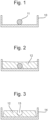
- a mould 10 is used to produce a first layer of the architecture.
- the mould may have a raised part 11 which corresponds to the desired shape and location of a channel in the architecture.
- a single raised part corresponding to a single channel is shown in Figure 11
- more complicated shapes of mould may be used to produce corresponding more complicated shapes of channel, such as those shown in Figure 8 , where a network of channels is provided, spanning from one side of the mould to the other.
- an uncured polymeric material is poured into the mould 10 in order to form a first layer 12.
- the first layer is then at least partially cured so that it retains the shape defined by the mould 10.
- the curing process may be carried out using any suitable method known in the art, including chemically initiated curing or (for e.g. a thermosetting material) curing induced by heat or radiation. If the first layer is partially cured, the layer may maintain the shape defined by the mould once it is removed from the mould, but may still retain the capacity to form further bonds with (i.e. to join to) further layers of polymeric material, as will be described below.
- an open channel 13 is formed at the location of the raised portion 11 of the mould. It will be noted that the first layer 12 has been turned over in Figure 3 such that the open channel faces upward. At this stage, the first layer 12 may be placed in a second mould 14 for use in subsequent steps, or, as described below, this may be done later on in the method. As shown in Figure 3 , the open channel is open to one of the surfaces of the first layer 12, and appears in cross-section as an indentation in the surface of the first layer 12. In the arrangement shown in in Figure 3 , the top surface of the first layer 12 is narrower than the bottom surface of the first layer.
- a meniscus may form, as shown in Figure 2 .
- This may result in the bottom surface of the first layer 12 in Figure 3 (i.e. the top surface of the first layer 12 in Figure 2 ) being longer than the top surface of the first layer 12 in Figure 3 , leading to the shape shown in Figure 3 .
- a meniscus may not form, or it may be negligible, so the cross-section of the first layer 12 may also be a rectangle, as opposed to the trapezium shown in Figure 3 .
- the cross-section of the open channel is part of an ellipse, such as a semicircle or an ellipse with part of its circumference removed, as shown in Figure 3 .
- different cross-sectional shapes of channel may be used.
- a cross-sectional shape which is an ellipse with less than half of its circumference, as shown in Figure 3 may be used.
- the flexibility of the material may allow removal of the first layer 12 from the mould.
- a semi-ellipse or an elliptical shape with more than half of its circumference removed may be used, in order to ease removal of the first layer 12 from the mould 10.
- a circle is a particular example of an ellipse.
- the cross-section may have any other geometry, in accordance with the desired shape of channel.
- the open channel 13 is then at least partially filled with a liquid 15, as shown in Figure 4 .
- the liquid 15 acts as a support material.
- the liquid 15 may be water, or may be any other suitable liquid which can be frozen at an appropriate temperature.
- additives which change the physical or chemical properties of the liquid may be added to the liquid. Such additives may, for example, react with the liquid to lower its temperature to freeze the liquid, or may change the freezing point of the liquid.
- the open channel may be completely filled with liquid, or, for liquids which expand when frozen, may be partially filled with enough liquid such that, once the liquid is frozen, it forms the desired shape of the rest of the channel.
- the extent to which the open channel is filled with liquid may be chosen to take account of the liquid changing in volume when it is frozen.
- the surface tension of the liquid may form a meniscus, which may have a shape which is convex when viewed in cross-section. That is, the channel is filled such that its surface extends above the surface of the layer in which the channel is disposed.
- the change in volume may cause the frozen liquid to expand or shrink, thus providing the desired shape of the support material in the channel.
- the liquid 15 in the open channel is then frozen (i.e. undergoes a phase change).
- the frozen liquid acts as a support material, which allows a second layer of polymer to be disposed on top of the first layer, and a closed channel formed between the first and second layers.
- the frozen liquid fills the space which will form the channel once the architecture has been formed.
- the terms "frozen” and “freezing” refer generally to solidifying a liquid. This term is not limited to the use of any particular temperature or liquid, and may be used to describe the process of changing the temperature of any liquid so that its phase changes to the solid phase.
- the freezing may take place at any suitable temperature, but the temperature is preferably low enough such that the liquid remains frozen during at least part of the subsequent process of curing the second layer, such that the frozen liquid can support the uncured liquid layer in the region of the channels.
- the freezing may take place at -30 degrees Celsius or less, preferably -50 degrees Celsius or less, and more preferably -80 degrees Celsius or less.
- the freezing may be carried out by placing the first layer and the liquid in the channel in an atmosphere of the appropriate temperature. Alternatively, or additionally, local cooling may be applied to the liquid in the channel to bring it to the desired temperature.
- an uncured polymeric material is poured onto the first layer 12 to form a second layer 16.
- the frozen liquid is encapsulated between the first layer and the second layer, and a closed channel is formed around the frozen liquid 15, defined between the first and the second layers 12, 16.
- the frozen liquid 15 supports the part of the second layer 16 which is over the open part of the channel, and this part of the second layer closes the channel.
- the second layer 16 may be poured into a second mould 14, in which the first layer 12 is disposed before pouring of the second layer 16.
- the second layer 16 is then at least partially cured.
- crosslinks i.e. chemical bonds
- This may result in the architecture forming one continuous block 1, as shown in Figures 6 and 7 .
- the first and second layers may no longer be separately identifiable, particularly if the first and second layers are formed using the same material. It will be appreciated that, if the first and second layers have different mechanical properties or are formed of different materials to each other, the layers are still joined but may nonetheless be separately identifiable.
- the frozen liquid i.e. the support material
- the frozen liquid may be allowed to return to a liquid state (i.e. to melt), and is removed from the channel.
- the solid may change phase directly to a gas (i.e. sublimate).
- the support material may be removed using air, either by suction, by blowing air through the channel, or by any other suitable process.
- the finished architecture 1, with the liquid removed, is shown in Figure 7 .
- the method as described above allows channels of very small diameter to be formed in the microfluidic architecture. Further, because the substance which supports the channel (i.e. the support material) when the second layer of uncured polymer is poured is a liquid, it can easily be removed once it has melted.
- a liquid 15 is used as the support material, and thus the liquid is solidified by freezing it.
- the support material may initially be a gas, and the phase transition may be from a gas to a liquid, then to a solid, or may be directly from a gas to a solid.
- the pattern is placed on the first layer, and the uncured elastomer is poured on top of the first layer and the pattern to encapsulate the support material, forming the second layer.
- the second layer is then at least partially cured.
- the support material may then undergo a phase change after the second layer has been formed and/or during the curing process of the second layer.
- the solid may change to a liquid phase (i.e. melt, as described above).
- the solid may sublimate (i.e. change directly to a gas phase from the solid phase). In both cases, the support material may be removed once it has undergone the phase change.
- the phase change may be caused by exposing the architecture to a change in temperature or pressure, or may occur at ambient temperature.
- Suitable materials which can be used for a support material which can sublimate include, but are not limited to, naphthalene and dry ice (solid carbon dioxide).
- the support material in which the support material is a solid when disposed on the first layer, also allows channels of very small diameter to be formed in the microfluidic architecture. Further, because the substance which supports the channel (i.e. the support material) undergoes a phase change, it can easily be removed after the phase change. It will be understood that such a phase change may provide for easier removal of the support material than known arrangements in which, for example, a material is dissolved.
- an uncured polymeric material may be poured into a mould to produce a third layer comprising at least one open channel.
- the mould may be of the same shape as the mould used in forming the first layer, or may be of a different shape, depending on the desired shape of the channels in the third layer.
- the mould may include one or more raised parts in the mould which extend above the level to which the uncured polymer is poured, in order to provide openings as described below. These may allow interconnections between the third layer and the other layers.
- the third layer is then at least partially cured so that it retains the shape defined by the mould.
- the layer may maintain the shape defined by the mould once it is removed from the mould, but may still retain the capacity to form further bonds with (i.e. to join to) further layers of polymeric material.
- the third layer is disposed on the second layer, with the surface of the third layer which does not have the open channel in contact with the second layer. This may be done whilst the second layer is partially cured. This allows the second and third layers to be subsequently cured together, such that bonds are formed between the second and third layer. That is, the third layer is joined to the second layer.
- the steps of closing the open channel in the third layer are carried out. That is, the open channel in the third layer is at least partially filled with a liquid (which is an example of a fluid), and the liquid in the open channel is then frozen (i.e. solidified).
- a liquid which is an example of a fluid
- an uncured polymeric material is poured onto the third layer to form a fourth layer.
- the frozen liquid is encapsulated between the third layer and the fourth layer, and a closed channel is formed around the frozen liquid, defined between the third and the fourth layers.
- the frozen liquid supports the part of the fourth layer which is over the open part of the channel.
- a closed channel is formed.
- the fourth layer is then at least partially cured.
- cross-links i.e. chemical bonds
- the third layer may develop between the third layer and the fourth layer, such that the architecture forms one continuous block.
- the third and fourth layers are joined to each other.
- further cross-links may also be formed between the second and third layers.
- the third and fourth layers may no longer be separately identifiable. It will be appreciated that, if the third and fourth layers have different mechanical properties or are formed of different materials to each other, the layers are joined but may nonetheless still be separately identifiable.
- the frozen liquid After the fourth layer is cured, or during the process of curing the fourth layer, the frozen liquid returns to a liquid state, and is removed from the channel.
- the liquid may be removed using air, either by suction or blowing air thorough the channel, or by any other suitable process.
- the steps of curing of the various layers may be timed so as to provide cross-linking between each of the layers that are in contact with each other. That is, all of the layers may be partially cured when they are first formed, and each subsequent layer may be disposed on the previous layer before curing of the previous layer is complete. This may ensure the structural integrity of the block, and allow the properties of the block to be controlled during manufacture by controlling the curing of each layer.
- FIG 14 A schematic representation of such a multi-layered architecture, comprising three architecture layers, is shown in Figure 14 , which shows a view similar to that of Figure 7 , but with multiple channels 31, and interconnections 32 between some channels in the same layer and between layers 30a, 30b, 30c.
- each of the architecture layers 30a, 30b, 30c in the finished architecture may be produced by the process above, such that each layer is made by combining two individual layers of polymeric material. That is, the first layer and second layer described above make up the first architecture layer 30a, and the third layer and fourth layer described above make up the second architecture layer 30b.
- joins between the layers 30a, 30b, 30c are shown in Figure 14 , it will be understood that these joins may not be separately identifiable in the finished architecture.
- the interconnections 32 may be formed using the same process as the channels 31 themselves. Thus, the interconnections may also be considered as further channels disposed within the architecture.
- the arrangement in Figure 14 contains three architecture layers 30a, 30b, 30c, with an interconnection between a channel in the first layer and a channel in the second layer, and with an interconnection between two channels in the third layer.
- this is merely an exemplary arrangement, and that any other combination of interconnections between channels in the same architecture layer and in different architecture layers is possible.
- an additional support material may be used which does not undergo a phase change.
- the additional support material may remain inside the finished architecture.
- the additional support material may be a substantially flat, flexible sheet.
- Such a sheet may be a sheet of of waxed paper, waxed plastic or a sheet of paper or plastics material coated with another organic coating, a metal foil (such as aluminium foil), or a sheet formed of or comprising an organic polymer.
- the thickness of such a flat, flexible sheet may be less than 1mm, and preferably 0.3-0.7mm, more preferably substantially 0.5mm.
- Figure 15 shows a first layer 12, similar to that shown in Figure 3 , but with three channels 13a, 13b, 13c. It will be understood that in the finished architecture, the channels 13 extend in a direction "into the page" in the cross section shown in Figure 15 .
- an additional support material 40 allows an additional channel 40a to be formed (as shown in Figure 20 ), spanning between the outer two channels 13a and 13c, and bypassing the middle channel 13b.
- the additional channel 40a extends in a direction from left to right in the view of Figure 20 . That is, the additional channel 40a extends in a direction perpendicular to the channels 13. In other words, the additional channel 40a crosses channel 13b without being in fluid communication with it, as described above, and links or bridges between channels 13a and 13c.
- the support material 15 (which can be considered as a "main" support material in this arrangement) is provided, as in the processes described above. For example, a liquid may be poured into the channels 13, and the liquid support material frozen, as described above in relation to Figure 4 .
- Figure 17 shows a view of Figure 16 after the support material 15 has been added, with the additional support material 40 being disposed within the (main) support material 15 and thus within the channels 13.
- Figure 19 shows the finished architecture, with three channels 13a, 13b, 13c and the additional support material 40 retained in the finished architecture.
- the additional channel 40a as shown in Figure 20 , may either naturally form around the additional support material 40, or may open up around the discontinuity caused by the additional support material when a fluid is provided in the architecture.
- the additional support material is shaped such that one channel is displaced relative to each other in a direction perpendicular to the direction in which the channel extends (i.e. in the vertical direction in the view of Figure 7 ). Because the additional support material is a substantially flat flexible sheet, it may abut the wall of the channel once the closed channel is formed, and does not interfere with the channel, or it may stay disposed within the channel without blocking flow through the channel, because of its thickness. Thus, it does not need to be removed from the architecture, and is retained in the finished architecture.
- the support material which does undergo a phase change i.e. the main support material
- the additional support material may have the further function of interacting with the fluid in the channel in an advantageous manner.
- the interaction may be a chemical interaction or a physical interaction.
- the additional support material may have a substance embedded therein, which can be absorbed from the additional support material by a fluid in the channel. This may allow the properties of the fluid to be modified.
- the additional support material may act as a filter to remove substances from a fluid in the channel (i.e. to absorb substances from the fluid, rather than the fluid absorbing substances from the additional support material).
- the additional support material may contain a substance which is retained in the additional support material, but causes a chemical reaction in the fluid in the architecture.
- the additional support material may have two functions, namely its function in forming the channel, as described above, and in interacting with the fluid in the finished architecture.
- a support material which does not undergo a phase change during the process of forming the channel is used, without the use of a support material which does undergo a phase change during the process of forming the channel.
- a support material may be, for example, the substantially flat, flexible sheet (as described above as an "additional support material"). It will be understood that in such arrangements, the flexible sheet acts as a (main) support material, rather than an additional support material.
- the support material which does not undergo a phase change during the process of forming the at least one channel, and is retained between the first and second layers replaces the support material which undergoes a phase change.
- the polymeric material used in the method above may be any curable polymer.
- the polymer elastomeric material i.e. an elastomer
- the elastomeric material may be (but is not limited to) one or more of a silicone, PDMS (polydimethylsiloxaneacrylic), a nitrile, a rubber, and polyurethane.
- the materials used for the first and second layers may be the same or different, and any combination of the after mentioned materials may be used.
- the polymeric material may be chosen according to the desired properties of the microfluidic architecture.
- silicone may be particularly suitable, or if a more rigid architecture is desired, more rigid polymers (such as acrylic) may be used.
- Different materials may be used for different layers, which may be used to combine properties of different materials (for example, to produce a semi-rigid architecture in which one layer, and thus one part of the architecture, has a different rigidity to another layer).
- the moulds which are used in the above method may be manufactured using additive layer manufacturing (3-D printing), and moulds may be produced as part of the method to provide the required layout of channels. However, the moulds may also be produced by any other suitable process. Examples of suitable moulds are shown in Figure 8 .
- the microfluidic architecture resulting from the above method may form a flexible sheet.
- the sheet may have two main surfaces separated in a thickness direction.
- the two main surfaces may extend substantially parallel to each other.
- the remaining surface or surfaces may extend in in the thickness direction (i.e. a direction perpendicular to the directions in which the main surfaces extend). These remaining surfaces may have a smaller area than the main faces, and can be considered to be side surfaces or edges of the sheet.
- the sheet may have a square or rectangular shape, such that the architecture has a cuboidal shape, with two of the faces being much larger than the rest of the faces, with the rest of the (smaller) faces forming the edges in the thickness direction.
- the flexible sheet is not limited to this particular shape, but rather that different geometries of flexible sheets are within the scope of the disclosure.
- the flexible sheet can be any shape suitable for acting as an interface between rigid surfaces, including parabolic, annular, planar, or a combination of some or all of these geometries.
- the architecture includes one or more openings into the channel. That is, the opening or openings allow fluid to be introduced into, or removed from, the architecture.
- the openings may be disposed on opposite edge surfaces of the sheet such that fluid can be introduced through one opening and removed through another opening.
- the at least one channel may be a network of channels. That is, there may be several distinct channels disposed in the architecture, which may be joined together or may be separate from each other.
- An example of such a network of channels is shown in Figure 9 .
- the network of channels may include a manifold and several branches in fluid connection with the manifold.
- the manifold may be a channel which forms a space arranged to store and/or retain fluid therein.
- the branches may be directly or indirectly (e.g. through a valve) connected to the manifold, such that fluid can be supplied to the branches from the manifold.
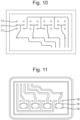
- one or more openings may be provided in a main surface of the architecture, as shown in Figure 10 .
- Such openings may be formed during the process of forming the first layer, by the provision of raised parts in the mould which extend above the level to which the uncured polymer is poured. These may take the form of posts (or columns) 18 which extend from the base of the mould.
- Figure 11 shows a corresponding mould which can be used to produce such a layer.
- a through-hole 17 is present in the first layer which subsequently forms an opening in the channel in the main surface of the architecture.
- the raised parts in a mould may also be used for other purposes.
- moulds used to form subsequent layers may include posts 18 which correspond to through-holes 17 in layers which have already been formed. These posts can be used to block the holes during the pouring of uncured polymer of subsequent layers, and to form further holes in the subsequent layer which are aligned with the holes in the layer which has already been formed.
- Openings in the main surface of the architecture may serve a variety of purposes.
- other components such as electronic components or fluid control components may be mounted into the architecture (i.e. disposed through at least one of the openings).
- valves may be inserted into the through holes (i.e. mounted to the architecture) in order to control the flow through the channel.
- Electronic components may also be mounted to the architecture via a tubing which is in fluid communication with an opening.
- valves there may be one or more channels (e.g. branches, as described above) which are not directly linked together (i.e. linked together inside the architecture). Rather, one or more valves may be provided which can be arranged such that the valves selectively allow or prevent fluid communication between two channels.
- the valves may be electronic or pneumatic valves which are mounted to (or in) the architecture. This may allow the architecture to be used as a flow control component.
- the microfluidic architecture may be used in a liner for a device such as a prosthetic, or other device which is in contact with a body part.
- the objects or surfaces may be medical or non-medical devices which are arranged for skin contact.
- the liner may also include a number of chambers which are arranged to store or retain a fluid.
- the channel is arranged to receive a fluid to cause an increase in at least one of the surface area or the volume of the microfluidic architecture, which may provide for improved cushioning of the body part, or gripping of the body part. An example of this is explained below with reference to Figures 12 and 13 .
- Figures 12 and 13 show an example of a liner 19 having a plurality of chambers 20 implemented in a prosthetic 21.
- the chambers 20 are connected by channels (and indeed the chambers and channels can together be considered a network of channels as described above. That is, the chambers themselves are also channels.
- Figure 12 shows a state in which the chambers 20 are not filled with a fluid, and thus have a small volume.
- Figure 13 shows a state in which fluid is supplied to the chambers 20.
- the fluid may be supplied via one or more openings as described above, and any number of chambers can be supplied through any number of openings.
- the increase in volume and/or surface area is caused by increased pressure within the chambers caused by the supply of fluid. Hence, it is apparent that the increase in surface area and/or volume of the liner at a localised region of the chambers is controllable by varying the fluid supplied to the chamber.
- the architecture is not limited to use as a liner between a body part and a prosthetic, but rather is suitable for acting as an interface between any suitable objects.
- the architecture can be used to provide cushioning in a ski boot, on a wheelchair, on a mattress, or in a helmet.
Landscapes
- Engineering & Computer Science (AREA)
- Health & Medical Sciences (AREA)
- Chemical & Material Sciences (AREA)
- Microelectronics & Electronic Packaging (AREA)
- Mechanical Engineering (AREA)
- General Health & Medical Sciences (AREA)
- Chemical Kinetics & Catalysis (AREA)
- Clinical Laboratory Science (AREA)
- Manufacturing & Machinery (AREA)
- Hematology (AREA)
- Analytical Chemistry (AREA)
- Dispersion Chemistry (AREA)
- Oral & Maxillofacial Surgery (AREA)
- Biomedical Technology (AREA)
- Public Health (AREA)
- Veterinary Medicine (AREA)
- Life Sciences & Earth Sciences (AREA)
- Vascular Medicine (AREA)
- Heart & Thoracic Surgery (AREA)
- Animal Behavior & Ethology (AREA)
- Transplantation (AREA)
- Cardiology (AREA)
- Computer Hardware Design (AREA)
- Casting Or Compression Moulding Of Plastics Or The Like (AREA)
- Micromachines (AREA)
- Physical Or Chemical Processes And Apparatus (AREA)
Claims (15)
- Verfahren zum Herstellen einer mikrofluidischen Architektur, die wenigstens einen Kanal umfasst, der darin angeordnet ist, wobei das Verfahren umfasst:Gießen eines ungehärteten Polymermaterials in eine Form, um eine erste Schicht (12) herzustellen;wenigstens teilweises Aushärten der ersten Schicht; undAusbilden des wenigstens einen Kanals durch:Anordnen eines Trägermaterials auf der ersten Schicht;Gießen eines ungehärteten Polymermaterials auf die erste Schicht, um eine zweite Schicht (16) auszubilden, um dadurch das Trägermaterial einzukapseln; undwenigstens teilweises Aushärten der zweiten Schicht, sodass die erste Schicht und die zweite Schicht zusammen die mikrofluidische Architektur ausbilden;wobei das Trägermaterial während des Vorgangs des Ausbildens des wenigstens einen Kanals keine Phasenänderung erfährt und das Trägermaterial zwischen der ersten und der zweiten Schicht zurückgehalten wird.
- Verfahren nach Anspruch 1, wobei das polymere Material ein elastomeres Material ist, das vorzugsweise eines oder mehrere umfasst von einem Silikon, Acryl, einem Nitril, einem Gummi und einem Polyurethan.
- Verfahren nach Anspruch 1 oder 2, das ferner umfasst:Gießen eines ungehärteten Polymermaterials in eine Form, um eine dritte Schicht zu erzeugen;wenigstens teilweises Aushärten der dritten Schicht;Anordnen der dritten Schicht auf der zweiten Schicht, bevor das Aushärten der zweiten Schicht abgeschlossen ist; undgemeinsames Aushärten der zweiten und der dritten Schicht, sodass Bindungen zwischen der zweiten und der dritten Schicht ausgebildet werden.
- Verfahren nach einem der vorhergehenden Ansprüche, wobei das Aushärten der zweiten Schicht aus Polymermaterial bewirkt, dass Bindungen zwischen wenigstens zwei der Schichten ausgebildet werden.
- Verfahren nach einem der vorhergehenden Ansprüche, wobei der Kanal wenigstens eine Öffnung durch wenigstens eine der Schichten umfasst, und vorzugsweise eine Mehrzahl von Öffnungen durch wenigstens eine der Schichten umfasst; und/oder
wobei der Kanal Öffnungen an gegenüberliegenden Enden der mikrofluidischen Architektur umfasst. - Verfahren nach Anspruch 5, das ferner das Anordnen einer elektronischen Komponente durch wenigstens eine Öffnung umfasst.
- Verfahren nach einem der vorhergehenden Ansprüche, wobei der wenigstens eine Kanal ein Netzwerk von Kanälen ist.
- Verfahren nach Anspruch 7, wobei das Netzwerk von Kanälen einen Verteiler beinhaltet, der angeordnet ist, um ein Fluid aufzunehmen und/oder zu lagern, und eine Mehrzahl von Abzweigungen in Fluidverbindung mit dem Verteiler steht.
- Verfahren nach einem der vorhergehenden Ansprüche, wobei das Trägermaterial ein im Wesentlichen flaches Blatt ist, vorzugsweise gewachstes Papier oder eine Metallfolie.
- Verfahren nach einem der vorhergehenden Ansprüche, wobei das Trägermaterial angeordnet ist, um mit einem in der mikrofluidischen Architektur angeordneten Fluid zu interagieren.
- Mikrofluidische Architektur, die durch das Verfahren nach einem der vorhergehenden Ansprüche erhalten wird.
- Mikrofluidische Architektur nach Anspruch 11, wobei die mikrofluidische Architektur ein mikrofluidischer Chip ist.
- Mikrofluidische Architektur nach Anspruch 11 oder 12, wobei die Architektur zwei Kanäle umfasst, die durch eine elektronische Komponente in selektiver Fluidverbindung verbunden sind.
- Mikrofluidische Architektur nach einem der Ansprüche 11-13, wobei wenigstens ein Kanal angeordnet ist, um ein Fluid aufzunehmen, um eine Vergrößerung von wenigstens einem des Oberflächenbereichs oder des Volumens der mikrofluidischen Architektur zu bewirken und/oder wenigstens ein Kanal angeordnet ist, um sich in dem Volumen zu verändern, um dadurch einen Fluss durch einen anderen Kanal in der Architektur zu ermöglichen oder zu verhindern.
- Einlage (19) für eine Vorrichtung, die für den Hautkontakt angeordnet ist und wenigstens eine mikrofluidische Architektur nach einem der Ansprüche 11-14 umfasst.
Applications Claiming Priority (2)
| Application Number | Priority Date | Filing Date | Title |
|---|---|---|---|
| GB201913529A GB201913529D0 (en) | 2019-09-19 | 2019-09-19 | Method And Apparatus |
| PCT/GB2020/052267 WO2021053350A1 (en) | 2019-09-19 | 2020-09-18 | Method of manufacturing a microfluidic architecture |
Publications (3)
| Publication Number | Publication Date |
|---|---|
| EP4031343A1 EP4031343A1 (de) | 2022-07-27 |
| EP4031343B1 true EP4031343B1 (de) | 2025-01-29 |
| EP4031343C0 EP4031343C0 (de) | 2025-01-29 |
Family
ID=68425402
Family Applications (1)
| Application Number | Title | Priority Date | Filing Date |
|---|---|---|---|
| EP20780302.4A Active EP4031343B1 (de) | 2019-09-19 | 2020-09-18 | Verfahren zur herstellung einer mikrofluidischen architektur |
Country Status (5)
| Country | Link |
|---|---|
| EP (1) | EP4031343B1 (de) |
| CN (2) | CN114761199B (de) |
| ES (1) | ES3009343T3 (de) |
| GB (1) | GB201913529D0 (de) |
| WO (1) | WO2021053350A1 (de) |
Citations (26)
| Publication number | Priority date | Publication date | Assignee | Title |
|---|---|---|---|---|
| DE19850046A1 (de) * | 1998-10-30 | 2000-05-11 | Ver Foerderung Inst Kunststoff | Verfahren und Vorrichtung zur Herstellung von Kunststoff-Formteilen mit Hohlräumen, Hinterschneidungen oder Kanälen mit mikroskopischen Abmessungen |
| WO2001001025A2 (en) * | 1999-06-28 | 2001-01-04 | California Institute Of Technology | Microfabricated elastomeric valve and pump systems |
| WO2002043615A2 (en) * | 2000-11-28 | 2002-06-06 | California Institute Of Technology | Microfabricated elastomeric valve and pump systems |
| US20020164816A1 (en) * | 2001-04-06 | 2002-11-07 | California Institute Of Technology | Microfluidic sample separation device |
| US20030156992A1 (en) * | 2000-05-25 | 2003-08-21 | Anderson Janelle R. | Microfluidic systems including three-dimensionally arrayed channel networks |
| US20030214057A1 (en) * | 2002-05-15 | 2003-11-20 | Zhili Huang | Microstructure fabrication and microsystem integration |
| WO2005084191A2 (en) * | 2004-02-13 | 2005-09-15 | The University Of North Carolina At Chapel Hill | Functional materials and novel methods for the fabrication of microfluidic devices |
| US20070012891A1 (en) * | 2004-12-08 | 2007-01-18 | George Maltezos | Prototyping methods and devices for microfluidic components |
| WO2007021762A2 (en) * | 2005-08-09 | 2007-02-22 | The University Of North Carolina At Chapel Hill | Methods and materials for fabricating microfluidic devices |
| WO2007061448A2 (en) * | 2005-05-18 | 2007-05-31 | President And Fellows Of Harvard College | Fabrication of conductive pathways, microcircuits and microstructures in microfluidic networks |
| WO2007092472A1 (en) * | 2006-02-03 | 2007-08-16 | Arkadij Elizarov | A microfluidic method and structure with an elastomeric gas-permeable gasket |
| CN101149364A (zh) * | 2007-11-10 | 2008-03-26 | 大连理工大学 | 水溶性牺牲层微流控芯片制备方法 |
| US20080305343A1 (en) * | 2007-06-08 | 2008-12-11 | Toohey Kathleen S | Self-healing materials with microfluidic networks |
| US7686907B1 (en) * | 2005-02-01 | 2010-03-30 | Brigham Young University | Phase-changing sacrificial materials for manufacture of high-performance polymeric capillary microchips |
| EP2213615A2 (de) * | 2002-09-25 | 2010-08-04 | California Institute of Technology | Mikrofluidische Großintegration |
| CN103009534A (zh) * | 2012-12-19 | 2013-04-03 | 中国科学院上海微系统与信息技术研究所 | 一种集成微结构的pdms薄膜制作方法 |
| US20130189888A1 (en) * | 2011-03-11 | 2013-07-25 | Jason F. Patrick | Self-Healing Composite Materials And Micro-Vascular Composites For Forming The Materials |
| US20150137429A1 (en) * | 2013-11-20 | 2015-05-21 | National Taiwan University Of Science And Technology | Fabrication method for a three dimensional micro-structure on polymers |
| US20160096176A1 (en) * | 2004-09-28 | 2016-04-07 | Landegren Gene Technology Ab | Microfluidic structure |
| US9458357B2 (en) * | 2011-03-02 | 2016-10-04 | Massachusetts Institute Of Technology | ph-sensitive sacrificial materials for the microfabrication of structures |
| WO2016155760A1 (en) * | 2015-03-27 | 2016-10-06 | Wageningen Universiteit | A method of manufacturing a microfluidic device |
| US9574172B2 (en) * | 2011-05-31 | 2017-02-21 | Tensive S.R.L. | Method for producing three-dimensional monolithic microfluidic devices |
| WO2019166279A1 (de) * | 2018-03-01 | 2019-09-06 | Robert Bosch Gmbh | Mikrofluidische vorrichtung |
| GB2572165A (en) * | 2018-03-20 | 2019-09-25 | Imperial College Sci Tech & Medicine | A flexible sheet with a hollow chamber |
| EP3177444B1 (de) * | 2014-08-05 | 2019-12-11 | MiniPumps, LLC | Flexible herstellung von polymeren rohren einschliesslich durchflussverändernder strukturen |
| EP3201690B1 (de) * | 2014-09-29 | 2019-12-18 | E. I. du Pont de Nemours and Company | Mikrofluidische vorrichtung und verfahren zur herstellung der mikrofluidischen vorrichtung aus einem lichtempfindlichen element |
Family Cites Families (13)
| Publication number | Priority date | Publication date | Assignee | Title |
|---|---|---|---|---|
| US7670324B2 (en) * | 1997-03-27 | 2010-03-02 | The Procter And Gamble Company | Disposable absorbent articles with replaceable absorbent core components having regions of permeability and impermeability on same surface |
| JP3967817B2 (ja) * | 1998-02-16 | 2007-08-29 | 独立行政法人理化学研究所 | キャピラリーカセット作成方法及びその装置 |
| US20050069462A1 (en) * | 2003-09-30 | 2005-03-31 | International Business Machines Corporation | Microfluidics Packaging |
| KR100927288B1 (ko) * | 2004-02-18 | 2009-11-18 | 히다치 가세고교 가부시끼가이샤 | 마이크로 유체시스템용 지지유닛 |
| KR20070085991A (ko) * | 2004-12-09 | 2007-08-27 | 히다치 가세고교 가부시끼가이샤 | 마이크로 유체 시스템용 지지유닛 및 그 제조방법 |
| US7427566B2 (en) * | 2005-12-09 | 2008-09-23 | General Electric Company | Method of making an electronic device cooling system |
| FR2897858B1 (fr) * | 2006-02-27 | 2008-06-20 | Commissariat Energie Atomique | Procede de fabrication d'un reseau de capillaires d'une puce |
| JP2009233812A (ja) * | 2008-03-27 | 2009-10-15 | Univ Nihon | 微細形状加工方法及びマイクロチップ |
| EP3024582A4 (de) * | 2013-07-22 | 2017-03-08 | President and Fellows of Harvard College | Anordnung mikrofluidischer kartuschen |
| US10443678B2 (en) * | 2014-09-29 | 2019-10-15 | Universidade Do Porto | Composite layer material for dampening external load, obtaining process, and uses thereof |
| US20190184393A1 (en) * | 2016-08-19 | 2019-06-20 | Exvivo Labs Inc. | Microfluidic device |
| US20180279702A1 (en) * | 2017-03-30 | 2018-10-04 | Hossein KARBAKHSH | Armpit perspiration absorbing pad |
| US11667084B2 (en) * | 2017-12-06 | 2023-06-06 | Safran Aircraft Engines | Method for producing an ordered array of interconnected acoustic microchannels |
-
2019
- 2019-09-19 GB GB201913529A patent/GB201913529D0/en not_active Ceased
-
2020
- 2020-09-18 CN CN202080068667.9A patent/CN114761199B/zh active Active
- 2020-09-18 WO PCT/GB2020/052267 patent/WO2021053350A1/en not_active Ceased
- 2020-09-18 ES ES20780302T patent/ES3009343T3/es active Active
- 2020-09-18 CN CN202410907374.5A patent/CN118876306A/zh active Pending
- 2020-09-18 EP EP20780302.4A patent/EP4031343B1/de active Active
Patent Citations (27)
| Publication number | Priority date | Publication date | Assignee | Title |
|---|---|---|---|---|
| DE19850046A1 (de) * | 1998-10-30 | 2000-05-11 | Ver Foerderung Inst Kunststoff | Verfahren und Vorrichtung zur Herstellung von Kunststoff-Formteilen mit Hohlräumen, Hinterschneidungen oder Kanälen mit mikroskopischen Abmessungen |
| WO2001001025A2 (en) * | 1999-06-28 | 2001-01-04 | California Institute Of Technology | Microfabricated elastomeric valve and pump systems |
| US20030156992A1 (en) * | 2000-05-25 | 2003-08-21 | Anderson Janelle R. | Microfluidic systems including three-dimensionally arrayed channel networks |
| WO2002043615A2 (en) * | 2000-11-28 | 2002-06-06 | California Institute Of Technology | Microfabricated elastomeric valve and pump systems |
| US20020164816A1 (en) * | 2001-04-06 | 2002-11-07 | California Institute Of Technology | Microfluidic sample separation device |
| US20030214057A1 (en) * | 2002-05-15 | 2003-11-20 | Zhili Huang | Microstructure fabrication and microsystem integration |
| EP2213615A2 (de) * | 2002-09-25 | 2010-08-04 | California Institute of Technology | Mikrofluidische Großintegration |
| WO2005084191A2 (en) * | 2004-02-13 | 2005-09-15 | The University Of North Carolina At Chapel Hill | Functional materials and novel methods for the fabrication of microfluidic devices |
| US20160096176A1 (en) * | 2004-09-28 | 2016-04-07 | Landegren Gene Technology Ab | Microfluidic structure |
| US20070012891A1 (en) * | 2004-12-08 | 2007-01-18 | George Maltezos | Prototyping methods and devices for microfluidic components |
| US7686907B1 (en) * | 2005-02-01 | 2010-03-30 | Brigham Young University | Phase-changing sacrificial materials for manufacture of high-performance polymeric capillary microchips |
| WO2007061448A2 (en) * | 2005-05-18 | 2007-05-31 | President And Fellows Of Harvard College | Fabrication of conductive pathways, microcircuits and microstructures in microfluidic networks |
| WO2007021762A2 (en) * | 2005-08-09 | 2007-02-22 | The University Of North Carolina At Chapel Hill | Methods and materials for fabricating microfluidic devices |
| WO2007092472A1 (en) * | 2006-02-03 | 2007-08-16 | Arkadij Elizarov | A microfluidic method and structure with an elastomeric gas-permeable gasket |
| US20080305343A1 (en) * | 2007-06-08 | 2008-12-11 | Toohey Kathleen S | Self-healing materials with microfluidic networks |
| CN101149364A (zh) * | 2007-11-10 | 2008-03-26 | 大连理工大学 | 水溶性牺牲层微流控芯片制备方法 |
| US9458357B2 (en) * | 2011-03-02 | 2016-10-04 | Massachusetts Institute Of Technology | ph-sensitive sacrificial materials for the microfabrication of structures |
| US20130189888A1 (en) * | 2011-03-11 | 2013-07-25 | Jason F. Patrick | Self-Healing Composite Materials And Micro-Vascular Composites For Forming The Materials |
| US9574172B2 (en) * | 2011-05-31 | 2017-02-21 | Tensive S.R.L. | Method for producing three-dimensional monolithic microfluidic devices |
| CN103009534A (zh) * | 2012-12-19 | 2013-04-03 | 中国科学院上海微系统与信息技术研究所 | 一种集成微结构的pdms薄膜制作方法 |
| US20150137429A1 (en) * | 2013-11-20 | 2015-05-21 | National Taiwan University Of Science And Technology | Fabrication method for a three dimensional micro-structure on polymers |
| EP3177444B1 (de) * | 2014-08-05 | 2019-12-11 | MiniPumps, LLC | Flexible herstellung von polymeren rohren einschliesslich durchflussverändernder strukturen |
| EP3201690B1 (de) * | 2014-09-29 | 2019-12-18 | E. I. du Pont de Nemours and Company | Mikrofluidische vorrichtung und verfahren zur herstellung der mikrofluidischen vorrichtung aus einem lichtempfindlichen element |
| WO2016155760A1 (en) * | 2015-03-27 | 2016-10-06 | Wageningen Universiteit | A method of manufacturing a microfluidic device |
| WO2019166279A1 (de) * | 2018-03-01 | 2019-09-06 | Robert Bosch Gmbh | Mikrofluidische vorrichtung |
| GB2572165A (en) * | 2018-03-20 | 2019-09-25 | Imperial College Sci Tech & Medicine | A flexible sheet with a hollow chamber |
| WO2019180431A1 (en) * | 2018-03-20 | 2019-09-26 | Imperial College Of Science, Technology And Medicine | Apparatus comprising a flexible sheet with a hollow chamber |
Also Published As
| Publication number | Publication date |
|---|---|
| EP4031343A1 (de) | 2022-07-27 |
| CN114761199B (zh) | 2024-07-26 |
| CN114761199A (zh) | 2022-07-15 |
| ES3009343T3 (en) | 2025-03-26 |
| GB201913529D0 (en) | 2019-11-06 |
| EP4031343C0 (de) | 2025-01-29 |
| WO2021053350A1 (en) | 2021-03-25 |
| US20220371232A1 (en) | 2022-11-24 |
| CN118876306A (zh) | 2024-11-01 |
Similar Documents
| Publication | Publication Date | Title |
|---|---|---|
| DE112011104891B4 (de) | 3D-Mikrofluid-Vorrichtungen auf der Grundlage von durchbrochenen thermoplastischen Elastomer-Membranen | |
| US9377151B2 (en) | Method for manufacturing an insulated pipe using a bag | |
| CN1921996B (zh) | Rtm成型方法及装置 | |
| CN101198397B (zh) | 用于空心纤维膜模块的集管和灌封空心纤维的方法 | |
| US20200346372A1 (en) | Techniques for casting from additively fabricated molds and related systems and methods | |
| CA2453411A1 (en) | Apparatus for making composite structures and method of making same | |
| EP3263207A1 (de) | Kopf eines moduls von hohlfasermembranen | |
| CN102427932A (zh) | 制造复合部件 | |
| BRPI0913340B1 (pt) | Estrutura microfluida, e método para sua produção | |
| CN101557875A (zh) | 用于接收或处理液体的设备 | |
| EP4031343B1 (de) | Verfahren zur herstellung einer mikrofluidischen architektur | |
| US12617129B2 (en) | Method of manufacturing a microfluidic architecture | |
| CN101495286B (zh) | 用于制造交联泡沫的方法 | |
| KR20180037175A (ko) | 복합 구조물의 제조 방법 | |
| CN113246363B (zh) | 用于制造泡沫部件的方法 | |
| KR102707707B1 (ko) | 중합체 미세 유체 밸브 | |
| EP4367215B1 (de) | Fluidische vorrichtung und verfahren zur herstellung davon | |
| CN114379077A (zh) | 低成本的纤维增强热固性复合材料3d打印构件后固化方法 | |
| CN104129082A (zh) | 用于纤维加固层压件的穿孔的真空膜 | |
| US20210402716A1 (en) | Fabrication Apparatuses and Methods | |
| CN210590213U (zh) | 一种耐油型密封橡胶圈 | |
| US12565723B2 (en) | Fabric with flow restricting core | |
| CN117021603B (zh) | 一种边缘封闭的高分子烧结多孔过滤吸附板及其加工方法 | |
| FR3047673A1 (fr) | Procede de fabrication d’un element fluidique et element fluidique fabrique a l’aide dudit procede | |
| JP2000297885A (ja) | 樹脂製複合管、及びその成形に用いる金型 |
Legal Events
| Date | Code | Title | Description |
|---|---|---|---|
| STAA | Information on the status of an ep patent application or granted ep patent |
Free format text: STATUS: UNKNOWN |
|
| STAA | Information on the status of an ep patent application or granted ep patent |
Free format text: STATUS: THE INTERNATIONAL PUBLICATION HAS BEEN MADE |
|
| PUAI | Public reference made under article 153(3) epc to a published international application that has entered the european phase |
Free format text: ORIGINAL CODE: 0009012 |
|
| STAA | Information on the status of an ep patent application or granted ep patent |
Free format text: STATUS: REQUEST FOR EXAMINATION WAS MADE |
|
| 17P | Request for examination filed |
Effective date: 20220414 |
|
| AK | Designated contracting states |
Kind code of ref document: A1 Designated state(s): AL AT BE BG CH CY CZ DE DK EE ES FI FR GB GR HR HU IE IS IT LI LT LU LV MC MK MT NL NO PL PT RO RS SE SI SK SM TR |
|
| DAV | Request for validation of the european patent (deleted) | ||
| DAX | Request for extension of the european patent (deleted) | ||
| GRAP | Despatch of communication of intention to grant a patent |
Free format text: ORIGINAL CODE: EPIDOSNIGR1 |
|
| STAA | Information on the status of an ep patent application or granted ep patent |
Free format text: STATUS: GRANT OF PATENT IS INTENDED |
|
| RIC1 | Information provided on ipc code assigned before grant |
Ipc: B01L 3/00 20060101ALI20240725BHEP Ipc: B29C 33/52 20060101ALI20240725BHEP Ipc: B29C 33/00 20060101ALI20240725BHEP Ipc: B81C 99/00 20100101ALI20240725BHEP Ipc: B29C 39/34 20060101ALI20240725BHEP Ipc: B29C 39/02 20060101AFI20240725BHEP |
|
| INTG | Intention to grant announced |
Effective date: 20240820 |
|
| GRAS | Grant fee paid |
Free format text: ORIGINAL CODE: EPIDOSNIGR3 |
|
| GRAA | (expected) grant |
Free format text: ORIGINAL CODE: 0009210 |
|
| STAA | Information on the status of an ep patent application or granted ep patent |
Free format text: STATUS: THE PATENT HAS BEEN GRANTED |
|
| RAP3 | Party data changed (applicant data changed or rights of an application transferred) |
Owner name: UNHINDR LTD |
|
| AK | Designated contracting states |
Kind code of ref document: B1 Designated state(s): AL AT BE BG CH CY CZ DE DK EE ES FI FR GB GR HR HU IE IS IT LI LT LU LV MC MK MT NL NO PL PT RO RS SE SI SK SM TR |
|
| REG | Reference to a national code |
Ref country code: GB Ref legal event code: FG4D |
|
| REG | Reference to a national code |
Ref country code: CH Ref legal event code: EP |
|
| REG | Reference to a national code |
Ref country code: DE Ref legal event code: R096 Ref document number: 602020045531 Country of ref document: DE |
|
| REG | Reference to a national code |
Ref country code: IE Ref legal event code: FG4D |
|
| U01 | Request for unitary effect filed |
Effective date: 20250204 |
|
| U07 | Unitary effect registered |
Designated state(s): AT BE BG DE DK EE FI FR IT LT LU LV MT NL PT RO SE SI Effective date: 20250210 |
|
| REG | Reference to a national code |
Ref country code: ES Ref legal event code: FG2A Ref document number: 3009343 Country of ref document: ES Kind code of ref document: T3 Effective date: 20250326 |
|
| PG25 | Lapsed in a contracting state [announced via postgrant information from national office to epo] |
Ref country code: RS Free format text: LAPSE BECAUSE OF FAILURE TO SUBMIT A TRANSLATION OF THE DESCRIPTION OR TO PAY THE FEE WITHIN THE PRESCRIBED TIME-LIMIT Effective date: 20250429 |
|
| PG25 | Lapsed in a contracting state [announced via postgrant information from national office to epo] |
Ref country code: PL Free format text: LAPSE BECAUSE OF FAILURE TO SUBMIT A TRANSLATION OF THE DESCRIPTION OR TO PAY THE FEE WITHIN THE PRESCRIBED TIME-LIMIT Effective date: 20250129 |
|
| PG25 | Lapsed in a contracting state [announced via postgrant information from national office to epo] |
Ref country code: NO Free format text: LAPSE BECAUSE OF FAILURE TO SUBMIT A TRANSLATION OF THE DESCRIPTION OR TO PAY THE FEE WITHIN THE PRESCRIBED TIME-LIMIT Effective date: 20250429 |
|
| PG25 | Lapsed in a contracting state [announced via postgrant information from national office to epo] |
Ref country code: HR Free format text: LAPSE BECAUSE OF FAILURE TO SUBMIT A TRANSLATION OF THE DESCRIPTION OR TO PAY THE FEE WITHIN THE PRESCRIBED TIME-LIMIT Effective date: 20250129 |
|
| PG25 | Lapsed in a contracting state [announced via postgrant information from national office to epo] |
Ref country code: GR Free format text: LAPSE BECAUSE OF FAILURE TO SUBMIT A TRANSLATION OF THE DESCRIPTION OR TO PAY THE FEE WITHIN THE PRESCRIBED TIME-LIMIT Effective date: 20250430 |
|
| PG25 | Lapsed in a contracting state [announced via postgrant information from national office to epo] |
Ref country code: SM Free format text: LAPSE BECAUSE OF FAILURE TO SUBMIT A TRANSLATION OF THE DESCRIPTION OR TO PAY THE FEE WITHIN THE PRESCRIBED TIME-LIMIT Effective date: 20250129 |
|
| U20 | Renewal fee for the european patent with unitary effect paid |
Year of fee payment: 6 Effective date: 20250909 |
|
| PGFP | Annual fee paid to national office [announced via postgrant information from national office to epo] |
Ref country code: GB Payment date: 20250828 Year of fee payment: 6 |
|
| PG25 | Lapsed in a contracting state [announced via postgrant information from national office to epo] |
Ref country code: CZ Free format text: LAPSE BECAUSE OF FAILURE TO SUBMIT A TRANSLATION OF THE DESCRIPTION OR TO PAY THE FEE WITHIN THE PRESCRIBED TIME-LIMIT Effective date: 20250129 |
|
| PG25 | Lapsed in a contracting state [announced via postgrant information from national office to epo] |
Ref country code: SK Free format text: LAPSE BECAUSE OF FAILURE TO SUBMIT A TRANSLATION OF THE DESCRIPTION OR TO PAY THE FEE WITHIN THE PRESCRIBED TIME-LIMIT Effective date: 20250129 |
|
| PGFP | Annual fee paid to national office [announced via postgrant information from national office to epo] |
Ref country code: IS Payment date: 20250917 Year of fee payment: 6 |
|
| PLBE | No opposition filed within time limit |
Free format text: ORIGINAL CODE: 0009261 |
|
| STAA | Information on the status of an ep patent application or granted ep patent |
Free format text: STATUS: NO OPPOSITION FILED WITHIN TIME LIMIT |
|
| 26N | No opposition filed |
Effective date: 20251030 |
|
| PGFP | Annual fee paid to national office [announced via postgrant information from national office to epo] |
Ref country code: ES Payment date: 20251017 Year of fee payment: 6 |