EP4031089B1 - Motorisierter gehwagen und zugehöriges steuerungsverfahren - Google Patents
Motorisierter gehwagen und zugehöriges steuerungsverfahren Download PDFInfo
- Publication number
- EP4031089B1 EP4031089B1 EP20785550.3A EP20785550A EP4031089B1 EP 4031089 B1 EP4031089 B1 EP 4031089B1 EP 20785550 A EP20785550 A EP 20785550A EP 4031089 B1 EP4031089 B1 EP 4031089B1
- Authority
- EP
- European Patent Office
- Prior art keywords
- verticalization
- walker
- electronic
- value
- force
- Prior art date
- Legal status (The legal status is an assumption and is not a legal conclusion. Google has not performed a legal analysis and makes no representation as to the accuracy of the status listed.)
- Active
Links
Images


Classifications
-
- A—HUMAN NECESSITIES
- A61—MEDICAL OR VETERINARY SCIENCE; HYGIENE
- A61H—PHYSICAL THERAPY APPARATUS, e.g. DEVICES FOR LOCATING OR STIMULATING REFLEX POINTS IN THE BODY; ARTIFICIAL RESPIRATION; MASSAGE; BATHING DEVICES FOR SPECIAL THERAPEUTIC OR HYGIENIC PURPOSES OR SPECIFIC PARTS OF THE BODY
- A61H3/00—Appliances for aiding patients or disabled persons to walk about
- A61H3/04—Wheeled walking aids for patients or disabled persons
-
- A—HUMAN NECESSITIES
- A61—MEDICAL OR VETERINARY SCIENCE; HYGIENE
- A61H—PHYSICAL THERAPY APPARATUS, e.g. DEVICES FOR LOCATING OR STIMULATING REFLEX POINTS IN THE BODY; ARTIFICIAL RESPIRATION; MASSAGE; BATHING DEVICES FOR SPECIAL THERAPEUTIC OR HYGIENIC PURPOSES OR SPECIFIC PARTS OF THE BODY
- A61H3/00—Appliances for aiding patients or disabled persons to walk about
- A61H3/008—Appliances for aiding patients or disabled persons to walk about using suspension devices for supporting the body in an upright walking or standing position, e.g. harnesses
-
- A—HUMAN NECESSITIES
- A61—MEDICAL OR VETERINARY SCIENCE; HYGIENE
- A61G—TRANSPORT, PERSONAL CONVEYANCES, OR ACCOMMODATION SPECIALLY ADAPTED FOR PATIENTS OR DISABLED PERSONS; OPERATING TABLES OR CHAIRS; CHAIRS FOR DENTISTRY; FUNERAL DEVICES
- A61G5/00—Chairs or personal conveyances specially adapted for patients or disabled persons, e.g. wheelchairs
- A61G5/10—Parts, details or accessories
- A61G5/14—Standing-up or sitting-down aids
-
- A—HUMAN NECESSITIES
- A61—MEDICAL OR VETERINARY SCIENCE; HYGIENE
- A61H—PHYSICAL THERAPY APPARATUS, e.g. DEVICES FOR LOCATING OR STIMULATING REFLEX POINTS IN THE BODY; ARTIFICIAL RESPIRATION; MASSAGE; BATHING DEVICES FOR SPECIAL THERAPEUTIC OR HYGIENIC PURPOSES OR SPECIFIC PARTS OF THE BODY
- A61H3/00—Appliances for aiding patients or disabled persons to walk about
- A61H2003/006—Appliances for aiding patients or disabled persons to walk about with forearm rests, i.e. for non-used arms
-
- A—HUMAN NECESSITIES
- A61—MEDICAL OR VETERINARY SCIENCE; HYGIENE
- A61H—PHYSICAL THERAPY APPARATUS, e.g. DEVICES FOR LOCATING OR STIMULATING REFLEX POINTS IN THE BODY; ARTIFICIAL RESPIRATION; MASSAGE; BATHING DEVICES FOR SPECIAL THERAPEUTIC OR HYGIENIC PURPOSES OR SPECIFIC PARTS OF THE BODY
- A61H3/00—Appliances for aiding patients or disabled persons to walk about
- A61H3/04—Wheeled walking aids for patients or disabled persons
- A61H2003/043—Wheeled walking aids for patients or disabled persons with a drive mechanism
-
- A—HUMAN NECESSITIES
- A61—MEDICAL OR VETERINARY SCIENCE; HYGIENE
- A61H—PHYSICAL THERAPY APPARATUS, e.g. DEVICES FOR LOCATING OR STIMULATING REFLEX POINTS IN THE BODY; ARTIFICIAL RESPIRATION; MASSAGE; BATHING DEVICES FOR SPECIAL THERAPEUTIC OR HYGIENIC PURPOSES OR SPECIFIC PARTS OF THE BODY
- A61H2201/00—Characteristics of apparatus not provided for in the preceding codes
- A61H2201/01—Constructive details
- A61H2201/0119—Support for the device
- A61H2201/0153—Support for the device hand-held
-
- A—HUMAN NECESSITIES
- A61—MEDICAL OR VETERINARY SCIENCE; HYGIENE
- A61H—PHYSICAL THERAPY APPARATUS, e.g. DEVICES FOR LOCATING OR STIMULATING REFLEX POINTS IN THE BODY; ARTIFICIAL RESPIRATION; MASSAGE; BATHING DEVICES FOR SPECIAL THERAPEUTIC OR HYGIENIC PURPOSES OR SPECIFIC PARTS OF THE BODY
- A61H2201/00—Characteristics of apparatus not provided for in the preceding codes
- A61H2201/01—Constructive details
- A61H2201/0161—Size reducing arrangements when not in use, for stowing or transport
-
- A—HUMAN NECESSITIES
- A61—MEDICAL OR VETERINARY SCIENCE; HYGIENE
- A61H—PHYSICAL THERAPY APPARATUS, e.g. DEVICES FOR LOCATING OR STIMULATING REFLEX POINTS IN THE BODY; ARTIFICIAL RESPIRATION; MASSAGE; BATHING DEVICES FOR SPECIAL THERAPEUTIC OR HYGIENIC PURPOSES OR SPECIFIC PARTS OF THE BODY
- A61H2201/00—Characteristics of apparatus not provided for in the preceding codes
- A61H2201/01—Constructive details
- A61H2201/0192—Specific means for adjusting dimensions
-
- A—HUMAN NECESSITIES
- A61—MEDICAL OR VETERINARY SCIENCE; HYGIENE
- A61H—PHYSICAL THERAPY APPARATUS, e.g. DEVICES FOR LOCATING OR STIMULATING REFLEX POINTS IN THE BODY; ARTIFICIAL RESPIRATION; MASSAGE; BATHING DEVICES FOR SPECIAL THERAPEUTIC OR HYGIENIC PURPOSES OR SPECIFIC PARTS OF THE BODY
- A61H2201/00—Characteristics of apparatus not provided for in the preceding codes
- A61H2201/12—Driving means
- A61H2201/1207—Driving means with electric or magnetic drive
- A61H2201/123—Linear drive
-
- A—HUMAN NECESSITIES
- A61—MEDICAL OR VETERINARY SCIENCE; HYGIENE
- A61H—PHYSICAL THERAPY APPARATUS, e.g. DEVICES FOR LOCATING OR STIMULATING REFLEX POINTS IN THE BODY; ARTIFICIAL RESPIRATION; MASSAGE; BATHING DEVICES FOR SPECIAL THERAPEUTIC OR HYGIENIC PURPOSES OR SPECIFIC PARTS OF THE BODY
- A61H2201/00—Characteristics of apparatus not provided for in the preceding codes
- A61H2201/14—Special force transmission means, i.e. between the driving means and the interface with the user
-
- A—HUMAN NECESSITIES
- A61—MEDICAL OR VETERINARY SCIENCE; HYGIENE
- A61H—PHYSICAL THERAPY APPARATUS, e.g. DEVICES FOR LOCATING OR STIMULATING REFLEX POINTS IN THE BODY; ARTIFICIAL RESPIRATION; MASSAGE; BATHING DEVICES FOR SPECIAL THERAPEUTIC OR HYGIENIC PURPOSES OR SPECIFIC PARTS OF THE BODY
- A61H2201/00—Characteristics of apparatus not provided for in the preceding codes
- A61H2201/16—Physical interface with patient
- A61H2201/1602—Physical interface with patient kind of interface, e.g. head rest, knee support or lumbar support
- A61H2201/1635—Hand or arm, e.g. handle
- A61H2201/1638—Holding means therefor
-
- A—HUMAN NECESSITIES
- A61—MEDICAL OR VETERINARY SCIENCE; HYGIENE
- A61H—PHYSICAL THERAPY APPARATUS, e.g. DEVICES FOR LOCATING OR STIMULATING REFLEX POINTS IN THE BODY; ARTIFICIAL RESPIRATION; MASSAGE; BATHING DEVICES FOR SPECIAL THERAPEUTIC OR HYGIENIC PURPOSES OR SPECIFIC PARTS OF THE BODY
- A61H2201/00—Characteristics of apparatus not provided for in the preceding codes
- A61H2201/50—Control means thereof
- A61H2201/5005—Control means thereof for controlling frequency distribution, modulation or interference of a driving signal
-
- A—HUMAN NECESSITIES
- A61—MEDICAL OR VETERINARY SCIENCE; HYGIENE
- A61H—PHYSICAL THERAPY APPARATUS, e.g. DEVICES FOR LOCATING OR STIMULATING REFLEX POINTS IN THE BODY; ARTIFICIAL RESPIRATION; MASSAGE; BATHING DEVICES FOR SPECIAL THERAPEUTIC OR HYGIENIC PURPOSES OR SPECIFIC PARTS OF THE BODY
- A61H2201/00—Characteristics of apparatus not provided for in the preceding codes
- A61H2201/50—Control means thereof
- A61H2201/5007—Control means thereof computer controlled
-
- A—HUMAN NECESSITIES
- A61—MEDICAL OR VETERINARY SCIENCE; HYGIENE
- A61H—PHYSICAL THERAPY APPARATUS, e.g. DEVICES FOR LOCATING OR STIMULATING REFLEX POINTS IN THE BODY; ARTIFICIAL RESPIRATION; MASSAGE; BATHING DEVICES FOR SPECIAL THERAPEUTIC OR HYGIENIC PURPOSES OR SPECIFIC PARTS OF THE BODY
- A61H2201/00—Characteristics of apparatus not provided for in the preceding codes
- A61H2201/50—Control means thereof
- A61H2201/5023—Interfaces to the user
- A61H2201/5025—Activation means
-
- A—HUMAN NECESSITIES
- A61—MEDICAL OR VETERINARY SCIENCE; HYGIENE
- A61H—PHYSICAL THERAPY APPARATUS, e.g. DEVICES FOR LOCATING OR STIMULATING REFLEX POINTS IN THE BODY; ARTIFICIAL RESPIRATION; MASSAGE; BATHING DEVICES FOR SPECIAL THERAPEUTIC OR HYGIENIC PURPOSES OR SPECIFIC PARTS OF THE BODY
- A61H2201/00—Characteristics of apparatus not provided for in the preceding codes
- A61H2201/50—Control means thereof
- A61H2201/5053—Control means thereof mechanically controlled
-
- A—HUMAN NECESSITIES
- A61—MEDICAL OR VETERINARY SCIENCE; HYGIENE
- A61H—PHYSICAL THERAPY APPARATUS, e.g. DEVICES FOR LOCATING OR STIMULATING REFLEX POINTS IN THE BODY; ARTIFICIAL RESPIRATION; MASSAGE; BATHING DEVICES FOR SPECIAL THERAPEUTIC OR HYGIENIC PURPOSES OR SPECIFIC PARTS OF THE BODY
- A61H2201/00—Characteristics of apparatus not provided for in the preceding codes
- A61H2201/50—Control means thereof
- A61H2201/5058—Sensors or detectors
- A61H2201/5061—Force sensors
-
- A—HUMAN NECESSITIES
- A61—MEDICAL OR VETERINARY SCIENCE; HYGIENE
- A61H—PHYSICAL THERAPY APPARATUS, e.g. DEVICES FOR LOCATING OR STIMULATING REFLEX POINTS IN THE BODY; ARTIFICIAL RESPIRATION; MASSAGE; BATHING DEVICES FOR SPECIAL THERAPEUTIC OR HYGIENIC PURPOSES OR SPECIFIC PARTS OF THE BODY
- A61H2201/00—Characteristics of apparatus not provided for in the preceding codes
- A61H2201/50—Control means thereof
- A61H2201/5058—Sensors or detectors
- A61H2201/5071—Pressure sensors
- A61H2201/5074—Pressure sensors using electric pressure transducers with proportional output
-
- A—HUMAN NECESSITIES
- A61—MEDICAL OR VETERINARY SCIENCE; HYGIENE
- A61H—PHYSICAL THERAPY APPARATUS, e.g. DEVICES FOR LOCATING OR STIMULATING REFLEX POINTS IN THE BODY; ARTIFICIAL RESPIRATION; MASSAGE; BATHING DEVICES FOR SPECIAL THERAPEUTIC OR HYGIENIC PURPOSES OR SPECIFIC PARTS OF THE BODY
- A61H2201/00—Characteristics of apparatus not provided for in the preceding codes
- A61H2201/50—Control means thereof
- A61H2201/5058—Sensors or detectors
- A61H2201/5092—Optical sensor
-
- A—HUMAN NECESSITIES
- A61—MEDICAL OR VETERINARY SCIENCE; HYGIENE
- A61H—PHYSICAL THERAPY APPARATUS, e.g. DEVICES FOR LOCATING OR STIMULATING REFLEX POINTS IN THE BODY; ARTIFICIAL RESPIRATION; MASSAGE; BATHING DEVICES FOR SPECIAL THERAPEUTIC OR HYGIENIC PURPOSES OR SPECIFIC PARTS OF THE BODY
- A61H2201/00—Characteristics of apparatus not provided for in the preceding codes
- A61H2201/50—Control means thereof
- A61H2201/5097—Control means thereof wireless
Definitions
- the invention relates to the field of walking aid devices, and more particularly to motorized walkers.
- the invention relates to a method for controlling a motorized walker making it possible to generate autonomy in its user.
- Technical aids for walking include, for example: canes, walking frames and walkers.
- Technical aids for walking allow a person with walking and/or balance disorders to regain a certain degree of autonomy.
- Some walking frames are designed to be used from a seated position and allow support during sit-to-stand transfers, but are difficult to use when walking (3-step walking: the person, leaning on the walking frame, moves one foot forward, then the other foot, then, still leaning on their feet, the person moves the walking frame forward).
- These walking frames are stable but inert supports, i.e. they do not actively assist the person in their movements.
- the easiest-to-use technical walking aids have wheels and cannot be used as support during sit-to-stand and stand-to-sit transfers, due to a lack of stability.
- a motorized walker has been proposed with lower handles and upper handles that can facilitate the user's transition from a sitting to a standing position ( US10292891 ).
- the sitting-standing and standing-sitting assistance is then carried out by a third party, in particular by staff in residential care homes for the elderly or in hospitals.
- such a device is not a walker and, as a verticalizer designed for verticalization, it does not facilitate the movement of an individual using the walker.
- its ability to be adapted to several walkers limits the possibilities of precisely controlling the verticalization angle.
- such a verticalization angle has a critical impact during the transition from a sitting position to a standing position.
- a walking assistance device capable of facilitating, on the one hand, the user's transition from a sitting position to a standing position, and, on the other hand, their movement.
- the invention therefore aims to remedy the drawbacks of the prior art.
- the invention aims to propose a motorized walker arranged so as to help the user move from a sitting position to a standing position while providing him with control means configured to control the movement of the walker intuitively.
- the invention further aims to propose a method for controlling a motorized walker, said method adapting to the movement of the user and not requiring said user to perform complex movements.
- Such a motorized walker by its electronic handles and its joint control of the verticalization and movement motors makes it possible to generate autonomy for its user. Indeed, unlike the walkers of the prior art which can only help a user to stand up or move, the arrangement and configuration of the motorized walker according to the invention allow a user to no longer have to depend on a third person for a majority of his movements.
- the motorized walker may optionally include one or more of the following features, alone or in combination:
- the central nervous system moves the hand or other end effector smoothly from one point to another during a gesture. It does this by minimizing the 'jerk' (the variation of force along a trajectory). Thus, the handles follow a trajectory that is best suited to human movement and therefore more comfortable.
- such a control method makes it possible, from a measurement of a force value applied to an electronic handle, to generate a control instruction to one of the verticalization motors and to one of the movement motors.
- the method can determine the intention of a user and control the motors of the walker to facilitate its realization.
- implementations of this aspect include computer systems, apparatuses, and corresponding computer programs stored on one or more computer storage devices, each configured to perform the actions of a method according to the invention.
- a system of one or more computers may be configured to perform particular operations or actions, including a method according to the invention, by installing software, firmware, hardware, or a combination of software, firmware, or hardware installed on the system.
- one or more computer programs may be configured to perform particular operations or actions by instructions that, when executed by a data processing apparatus, cause the apparatus to perform the actions.
- each block in the flowcharts or block diagrams may represent a system, device, module, or code, which includes one or more executable instructions to implement the specified logical function(s).
- front part and rear part may be defined as all of the elements of the motorized walker located respectively on either side of a longitudinal section plane of a front view of the motorized walker, said longitudinal section plane passing through the center of gravity of said motorized walker.
- the rear part being that intended to accommodate a user.
- axis perpendicular to the ground ", and represented by the y axis in the figures, corresponds to an axis forming an angle substantially equal to 90° with any surface in contact with the wheels of the motorized walker.
- the expression “ electronic handle ” corresponds for example to a device for supporting the weight of a user, arranged to accommodate a hand of said user and comprising within it one or more sensors arranged so as to allow a force to be measured.
- Force within the meaning of the invention corresponds to a mechanical action exerted by a user on a surface and in particular on the electronic handle.
- a “force “ applied ” corresponds in the sense of the invention to a user exerting pressure on the outer surface of said electronic handle.
- component of a force corresponds to a projection of a force on a direction.
- a “first component” thus corresponds for example to a projection of a force along a Z axis represented by an axis orthogonal to the longitudinal axis of the electronic handle.
- a “ second component” thus corresponds to a projection of a force along an X axis, corresponding to the longitudinal axis of the electronic handle.
- fixation corresponds to the joining of two separate entities to each other.
- two entities may have a removable or non-removable fixation.
- removable corresponds according to the invention to the ability to be detached, removed or dismantled easily without having to destroy the fixing means either because there is no fixing means or because the fixing means are easily and quickly removable (e.g. notch, screw, tab, lug, clips).
- the object is not fixed by welding or by another means not provided to allow the object to be detached.
- non-removable ” or “ irremovable ” fastener corresponds according to the invention to the ability not to be detached, removed or dismantled without having to destroy the fastening means either because there is no fastening means or because the fastening means are not easily and quickly dismantled.
- non-removable it should be understood that the object is fixed by welding or more generally by any irreversible means of securing.
- tubular corresponds to a substantially elongated element forming a conduit whose lumen is enclosed by a wall of said conduit. Such a lumen thus designates a hollow interior space circumscribed by the wall of the conduit.
- substantially is associated with a particular value, it is understood to mean a value varying by less than 30% from the compared value, preferably by less than 20%, even more preferably by less than 10%.
- substantially identical is used to compare shapes then the vectorized shape varies by less than 30% from the compared vectorized shape, preferably by less than 20%, even more preferably by less than 10%.
- a “polymer” is either a copolymer or a homopolymer.
- a “copolymer” is a polymer that combines several different monomer units and a “homopolymer” is a polymer that groups together identical monomer units.
- a polymer can for example be a thermoplastic or thermosetting polymer.
- thermoplastic polymer or " thermoplastic" means a polymer that can be repeatedly softened or melted under the action of heat and that adopts new shapes by the application of heat and pressure.
- thermoplastics are, for example: high-density polyethylene (HDPE), polyethylene terephthalate (PET), polyvinyl chloride (PVC), polystyrene (PS) or acrylonitrile butadiene styrene (ABS).
- thermosetting polymer is understood to mean a plastic material that irreversibly transforms into an insoluble polymer network through polymerization. Once the shape of the thermosetting polymer has been fixed and cooled, it can no longer be changed by heat.
- thermosetting polymers are: unsaturated polyesters, polyimides, polyurethanes or vinyl esters, which can be epoxy or phenolic.
- coupled means connected, directly or indirectly, with one or more intermediate elements.
- Two elements can be coupled mechanically, electrically or linked by a communication channel.
- process refers to actions and/or processes of a data processing system, for example a computer system or an electronic computing device, which manipulates and transforms data represented as physical (electronic) quantities in the memories of the computer system or other devices for storing, transmitting or displaying information. These operations may be based on applications or software.
- application means any expression, code or notation, of a set of instructions intended to cause a processing of data to perform a particular function directly or indirectly (eg after a conversion operation to other code).
- program code may include, but are not limited to, a subroutine, a function, an executable application, source code, object code, a library and/or any other sequence of instructions designed for execution on a computer system.
- processor refers to at least one hardware circuit configured to execute instructions contained in the program code.
- the hardware circuit may be an integrated circuit.
- Examples of a processor include, but are not limited to, a central processing unit (CPU), a network processor, a vector processor, a digital signal processor (DSP), a field-programmable gate array (FPGA), a programmable logic array (PLA), an application-specific integrated circuit (ASIC), a programmable logic circuit, and a controller.
- learning within the meaning of the invention corresponds to a method designed to define a function f for calculating a value of Y from a base of n labeled observations (X1...n, Y1...n) or unlabeled (X1...n).
- a function may correspond to a prediction model. Learning may be said to be supervised when it is based on labeled observations and unsupervised when it is based on unlabeled observations.
- learning is advantageously used for customizing the operation of the walker and therefore adapting it to a particular user.
- a " predictive model” is any mathematical model that allows a volume of data to be analyzed and relationships to be established between factors that enable the assessment of risks or opportunities associated with a specific set of conditions, in order to guide decision-making towards a specific action.
- human-machine interface within the meaning of the invention corresponds to any element allowing a human being to communicate with an electronic device.
- motorized means an apparatus or device equipped with any known suitable means (e.g. motor) making it possible to generate movement of all or part of the device with which said means is associated.
- Walking assistance devices such as motorized walkers generally do not provide smooth assistance with verticalization (moving from a sitting to a standing position) of the user and then assistance with movement.
- the means of verticalization are generally absent or provided by additional aid devices for caregivers.
- the present invention proposes to overcome this by detailing a motorized walker comprising electronic handles arranged so as to allow the user to stand upright and capable of controlling the movement of the walker according to the user's instructions.
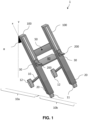
- the invention relates to a motorized walker 1.
- a motorized walker 1 comprises a chassis 10 having a front part 10a and a rear part 10b.
- the chassis 10 may be made of metal, a metal alloy, a polymer, a composite assembly or a mixture of these materials.
- the chassis 10 is made of stainless steel.
- the chassis 10 may be covered with a shell. Such a shell may be made of polymers, composites or any other materials.
- a motorized walker 1 comprises a pair of wheels 11 arranged to support the rear part 10b of the chassis 10, and at least one wheel 12 which is arranged to support the front part 10a of the chassis.
- the chassis preferably has two wheels at the rear and two wheels at the front.
- the motorized walker 1 will comprise motorized wheels arranged to support the rear part 10b of the chassis 10.
- the only motorized wheels may be those supporting the rear part 10b of the chassis 10.
- the walker 1 is a motorized walker.
- at least one of these wheels is coupled to a movement motor 20.
- a movement motor 20 is arranged at the level of a wheel and is not directly visible on the figure 1 . It is hidden by a shell positioned at the level of one or more wheels.
- Any type of electric motor can be used, preferably a brushless motor such as a brushless electronically commutated motor.
- a motorized walker 1 according to the invention may further comprise a proximity sensor 50.
- a proximity sensor 50 is preferably configured to measure a proximity value between the trunk of a user of the motorized walker 1 and the proximity sensor 50.
- the proximity sensor 50 being generally fixed to the chassis 10 or to an element of the chassis, this makes it possible to measure a proximity value between the trunk of a user of the motorized walker 1 and the chassis 10.
- a motorized walker 1 according to the invention may further comprise a tray 60.
- a tray 60 is generally arranged so as to be able to support the weight of everyday convenience objects, but it may preferably be arranged so as to be able to support the weight of a given user.
- a motorized walker 1 according to the invention may include a tray 60 fixed to the chassis and/or to the verticalization ramps.
- the chassis 10 of the motorized walker 1 according to the invention is equipped with two verticalization ramps 100.
- the two verticalization ramps are fixed irremovably to the chassis 10.
- they can alternatively be fixed to the chassis 10 in a removable manner.
- these verticalization ramps 100 have a longitudinal axis (denoted “x” in relation to the figure 1 ) making an angle (noted “ ⁇ ” in relation to the figure 1 ) with an axis perpendicular to the ground (noted “y” in relation to the figure 1 ) between 20° and 40°.
- these verticalization ramps 100 have a longitudinal axis making an angle with an axis perpendicular to the ground of between 25° and 35°, more preferably substantially equal to 30° and even more preferably equal to 30°. Indeed, it has been determined in the context of the present invention that such an inclination allows effective verticalization of a subject and results in the least instability of the subject during verticalization.
- each of these verticalization ramps 100 is associated with an electronic handle 200 movable in translation along the verticalization ramp 100 with which it is associated.
- the electronic handles 200 are arranged so as to be able to train a user from a sitting position to a standing position, i.e. to undergo verticalization.
- the motorized walker 1 also comprises at least one verticalization motor 30.
- the at least one verticalization motor 30 is preferably arranged to control a movement of the electronic handles 200 along the verticalization ramps 100.
- a single motor could suffice, it would simultaneously activate the two handles being coupled thereto via torque transmission means.
- Any type of electric motor may be used, preferably a brushless motor such as a brushless electronically commutated motor.
- each of the verticalization ramps 100 may comprise a verticalization motor 30.
- the walker advantageously comprises two verticalization motors 30, each being coupled to one of the verticalization ramps 100.
- the motors are preferably positioned at one end of the verticalization ramp 100.
- the motors are positioned at the lower end of each of the verticalization ramps 100.
- the loading forces on the handle being directed downwards, it is simpler to position the motor at the bottom because the recovery of the forces can then be done at the level of the upper bearing, which stresses the screw in traction. There is therefore no risk of buckling of the screw.
- the position of the motor at the bottom makes it possible to reduce the size of the device in height.
- each of the verticalization ramps 100 comprises a transmission system which, driven by the verticalization motor 30, allows the electronic handles 200 to be moved along the verticalization ramps 100.
- the movement of the electronic handles 200 along the verticalization ramps 100 is advantageously capable of moving a user of the walker from the sitting position to the standing position.
- the movement of the electronic handles 200 is preferably a synchronized movement so as not to cause the user to become unbalanced.
- the transmission system may correspond to any means arranged to transmit a rotational movement (verticalization motor 30) into a translational movement (electronic handle 200). It may for example be selected from the following systems: rack, crank connecting rod, cam, belt, screw-nut. When the motorized walker 1 has only one verticalization motor 30 then the transmission system is arranged so as to allow a translational movement of the two electronic handles 200.
- each of the verticalization ramps comprises a motorized screw-nut system driven by the verticalization motor 30.
- a motorized screw-nut system driven by the verticalization motor 30.
- Such a system comprises a screw 110 extending from the verticalization motor 30 to a guide device 120 and a nut 130 capable of being moved along the screw 110.
- the verticalization ramps 100 comprise a guide device 120 located opposite the verticalization motor relative to the screw.
- a guide device 120 makes it possible both to guide the screw 110 but also to absorb part of the axial forces induced by the user.
- a screw 110 that can be used has a length value much higher than the diameter value and must withstand significant axial forces transmitted by the handles. Thus, it must preferably be guided at its two ends.
- the screw is placed in a guide device 120 comprising a ball bearing.
- the guide device 120 is arranged so as to block the screw 110, in particular to prevent any rotational movement of said screw 110, when the motorized walker 1 is stationary.
- the guide device 120 is arranged so as to block the screw 110, in particular to prevent any rotational movement of said screw 110, when the motorized walker 1 is stationary.
- the screw 110 may be any type of screw suitable for a screw-nut system. In particular, it may be selected from screws with trapezoidal, square, triangular threads or even ball screw-nuts.
- the screw 110 may be coupled to the verticalization motor 30 via a sleeve 140 allowing the screw-motor coupling.
- a sleeve 140 is preferably arranged so as to allow a flexible coupling between the screw 110 and the verticalization motor 30. Such a flexible coupling makes it possible to isolate the motor from the axial forces of the screw.
- the electronic handles 200, coupled to the verticalization ramps 100 must be able to support at least part of the weight of an individual given that one of their functions is to move an individual from a seated position to a standing position.
- the electronic handles 200 and the verticalization ramps 100 are arranged so as to be able to support a weight of at least 30 kilograms, preferably at least 50 kilograms and more preferably at least 70 kilograms.
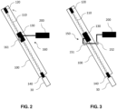
- an internal guidance 160 one embodiment of which is illustrated in figure 2
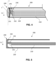
- an external guide 150 one embodiment of which is illustrated in figure 3 .
- the electronic handles 200 and the verticalization ramps 100 are coupled via an internal guidance system 160.
- the internal guidance system 160 may for example comprise a rail or a slide inside the verticalization ramp 100 on which an element fixed to an electronic handle 200 will slide.
- an element 161 fixed to an electronic handle 200 will slide along the internal surface of a verticalization ramp so as to transfer part of the forces undergone by the verticalization handle.
- Such an element 161 may for example correspond to a ball bearing.
- the electronic handles 200 and the verticalization ramps 100 are coupled via an internal guidance system, and said internal guidance system comprises a rail on which an element fixed to the electronic handle 200 slides.
- the electronic handles 200 and the verticalization ramps 100 are coupled via an external guidance system.
- the external guidance system may for example comprise a rail or a slide outside the verticalization ramp 100 on which an element fixed to an electronic handle 200 will slide.
- the external guidance system may comprise bearings 151,152 positioned in contact with a front face and/or a rear face of the verticalization ramp 100.
- the verticalization ramps 100 comprise at least one end-of-travel sensor.
- an end-of-travel sensor or position sensor or end-of-travel switch is preferably selected from: an optoelectronic sensor, a through-beam phototransistor, a roller push switch, a roller lever switch, a spring rod and a magnetic loop rod.
- a through-beam phototransistor is used as an end-of-travel sensor and is located at the bottom of a verticalization ramp, for example in a jack. It makes it possible to initialize the position of the handle when the device is powered up. Once the origins have been taken, the position of the handle can be known using the Hall effect sensors integrated into the motor.
- the electronic handles 200 configured to measure a force applied to them can be equipped with force sensors, torque sensors, pressure sensors, strain gauges, piezoelectric technology or even simple button sensors.
- the electronic handles 200 used in the context of the invention comprise a coupling between a photoelectric cell and a shutter element.
- a photoelectric cell may in particular correspond to a sensor consisting of an infrared emitter and a receiver placed opposite. The emission zone is therefore a line of infrared light.
- a shutter element such as a flag penetrates between the emitter and the receiver, the quantity of light received by the receiver is increasingly weak.
- the measurement of the current at the sensor output is proportional to the quantity of light measured and therefore to the distance of penetration of the flag. This distance can then be related to the force, applied to the handle, which caused the movement.
- such an electronic handle allows the control of a motorized walker without the user wearing sensors or activating buttons (or other interface).
- Such an arrangement makes it possible to detect a force, applied to the handle, greater than or equal to two kilograms but also much lower.
- such an arrangement makes it possible to determine a value of the force applied and does not simply detect the exceeding of a threshold.
- a processor may process information differently depending on the level of force that has been applied to the electronic handle.
- an electronic handle 200 is arranged so as to allow the measurement of at least one component of a force applied to it.
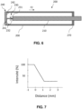
- a handle according to the invention comprises a central part 210 and an outer casing 220.
- the central part 210 of an electronic handle 200 may have a substantially cylindrical shape. However, as can be seen in the illustration of the figure 4 , preferably, the central part 210 comprises at least one portion having a section comprising an edge. For example, it has a polygon-shaped section.
- the central part 210 is made with a material preferably having a Young's modulus at least equal to 60 GPa, for example at least equal to 175 GPa, more preferably greater than 200 GPa. This makes it possible to give the central part 210 a rigidity suitable for its use in the electronic handle according to the invention.
- the central part 210 may be made of metal, a metal alloy, polymer or a composite assembly. Preferably, the central part 210 is made of stainless steel.
- the central part 210 preferably has a minimum length of 100 mm or 300 mm and a maximum length of 500 mm.
- the outer casing 220 of an electronic handle 200 may have a substantially tubular shape, preferably tubular. It may comprise at least one portion having a section comprising an edge. Nevertheless, preferably, it has a section of ellipsoidal shape and more preferably circular.
- the outer casing 220 is made with a material preferably having a Young's modulus of less than 200 GPa, more preferably less than 150 GPa and even more preferably less than 100 GPa. Such a constitution and the existence of elasticity at the level of the outer casing 220 makes it possible to improve the performance of the electronic handle according to the invention.
- the outer shell 220 may be made of metal, a metal alloy, a polymer, or a composite assembly. Preferably, the outer shell 220 is made of aluminum.
- the outer casing 220 preferably has a minimum length of 300 mm and a maximum length of 500 mm. Furthermore, the outer casing 220 may have an outer diameter of between 20 mm and 40 mm and a wall thickness of between 1 mm and 3 mm.
- the outer casing 220 is arranged so as to be able, under the effect of a force comprising a vertical component, to move by at least one tenth, preferably one thousandth of a millimeter in translation relative to an axis orthogonal to a longitudinal axis of the central part 210.
- a force component value can be quantified from one tenth, preferably one thousandth of a millimeter of displacement.
- a displacement of at least one tenth, preferably one thousandth of a millimeter may preferably correspond to a displacement of at least 0.001 millimeter to 1 millimeter.
- the outer casing 220 may be arranged so as to be able, under the effect of a force comprising a horizontal component, to move by at least one tenth, preferably at least one thousandth, of a millimeter in translation relative to a longitudinal axis of the central part 210.
- a force component value may be quantified from one tenth, preferably one thousandth, of a millimeter of displacement.
- An electronic handle 200 comprises a first photoelectric cell 230.
- Photoelectric cells are electronic devices that typically include a light-emitting diode capable of emitting light pulses, typically in the near infrared (e.g. 850 to 950 nm). This light is received or not by a photodiode or phototransistor depending on the presence or absence of an object in the path of the light pulses. The photoelectric current created can be amplified and then analyzed.
- a light-emitting diode capable of emitting light pulses, typically in the near infrared (e.g. 850 to 950 nm). This light is received or not by a photodiode or phototransistor depending on the presence or absence of an object in the path of the light pulses.
- the photoelectric current created can be amplified and then analyzed.
- a photoelectric cell may be selected from a through-beam type, reflex type, or proximity type photoelectric cell. Furthermore, it is possible to use optical fibers to modify the arrangement of the photoelectric cells within the scope of the invention.
- a photoelectric cell is preferably a barrier type photoelectric cell for which the barrier is constituted by the shutter element 240.
- Such photoelectric cells can usually be inexpensive but robust compared to commonly used sensors.
- the first photoelectric cell 230 comprises a first diode 231 capable of emitting a light beam.
- the diode of a photoelectric cell according to the invention may correspond to an infrared diode.
- the first photoelectric cell 230 comprises a first receiver 232 arranged to receive the light beam emitted by the first diode.
- the light beam emitted by the first diode is directed directly towards the first receiver 232.
- the first photoelectric cell 230 is configured to generate a proportional current (e.g. intensity or voltage) to a quantity of photons received by the first receiver 232.
- a proportional current e.g. intensity or voltage
- the first receiver 232 which as a light transducer will generate a modification of an electrical signal in response to the light beam incident on its surface.
- the first receiver 232 may for example be a photoconductor, a photodiode or a phototransistor.
- a photoelectric cell according to the invention is configured to generate an electric current whose intensity or voltage will be proportional to the quantity of photons received by the receiver.
- the electronic handle 200 comprises a first shutter element 240 which is capable of, or arranged so as to, modify the quantity of photons received by the first receiver 232.
- this modification of the quantity of photons received is a function of the position of the first shutter element 240 relative to the first photoelectric cell 230.
- a sealing element 240 within the meaning of the invention may be made of metal, a metal alloy, polymer or a composite assembly.
- the sealing element 240 is made of polymer, more preferably thermoplastic polymer.
- the shutter element 240 may comprise a protuberance 241 arranged so as to be positioned between the diode 231 and the receiver 232 of the photoelectric cell 230.
- the protuberance 241 may be fixed in a removably or non-removably manner to the shutter element 240. Furthermore, in the absence of a protuberance 241, it is the shutter element which is housed between the diode 231 and the receiver 232.
- first photoelectric cell 230 and the first shutter element 240 can be movable at least in part relative to each other. Indeed, it is in particular the movement of one relative to the other, preferably of at least a part relative to each other, which will allow a measurement of a component of a force applied to the electronic handle 200 according to the present invention.
- figure 5 for example has means 242 for fixing the closing element 240 to the outer casing 220.
- the fixing is preferably a removable fixing.
- the fixing will be carried out in such a way that a force F1 applied to the electronic handle 200, if it is sufficient to at least partially move the outer casing 220 then it will cause a modification of the quantity of photons received by the first receiver 232.
- the position of the first shutter element 240 making it possible to influence the quantity of photons received by the first receiver 232 then, the modification of the quantity of photons received by the first receiver 232 will be correlated, preferably proportional, to a first component of the force having been applied to the electronic handle 200.
- the fixing will be carried out so that a force F2 applied to the electronic handle 200, if it is sufficient to at least partially move the outer casing 220 then it will cause a modification of the quantity of photons received by the first receiver 232.
- the position of the first shutter element 240 making it possible to influence the quantity of photons received by the first receiver 232 then, the modification of the quantity of photons received by the first receiver 232 will be correlated, preferably proportional, to a second component of the force having been applied to the electronic handle 200.
- the handle may comprise an element 270 capable of elastic deformation, for example made of polymer, so as to allow a translation of the outer casing 220 relative to the central part 210.
- the electronic handle according to the present invention may comprise a sensor of a vertical or horizontal force component passing through a measurement of a displacement of the outer casing relative to the central part 210, the displacement being caused by a force comprising a vertical component or a horizontal component.
- the electronic handle 200 comprises a fixed horizontal axis, for example made of steel, capable of being connected to a walking assistance device (eg walker) and which serves as a reference. It also comprises an outer casing 220 which can take the form of an outer tube which can move, under the effect of the horizontal component of the force, by one tenth of a millimeter in translation relative to the central axis and which, under the effect of the vertical component of the force, deforms in the sagittal plane like a fixed beam. The measurement of this force can be carried out by a processor for example placed in the electronic handle 200 or in the walking assistance device.
- a processor for example placed in the electronic handle 200 or in the walking assistance device.
- a photoelectric cell as used in the context of the present invention is preferably configured so as to be able to generate an electrical signal whose intensity or voltage is correlated, preferably proportional, to the position of a shutter element.
- the modification of the quantity of photons received by the receiver will be proportional to a component of the force having been applied to the electronic handle 200.
- the relationship between distance and current is preferably linear over at least 1 mm.
- an electronic handle 200 may also comprise at least one second photoelectric cell 250.
- This second photoelectric cell 250 may share the same characteristics as the first photoelectric cell 230 and in particular its preferred or advantageous characteristics.
- the second photoelectric cell 250 comprises a second diode 251 capable of emitting a light beam. It also comprises a second receiver 252 arranged to receive said light beam.
- the second photoelectric cell 250 is arranged so that a force applied to the electronic handle 200 is capable of causing a modification of the quantity of photons received by the second receiver 252.
- the force applied to the electronic handle 200 will be capable of causing a modification of the quantity of photons received by the second receiver 250 if it is capable of at least partially moving the outer casing 220.
- the modification of the quantity of photons received is proportional to a second component of the force having been applied to the electronic handle 200.
- the photoelectric cells 230, 250 can be indirectly fixed to the central part 210.
- an electronic handle 200 may also comprise an electronic card 280.
- Such an electronic card 280 may be configured to measure the output voltage of the photoelectric cell and then transform it into digital data.
- the electronic card 280 is configured to sample the current measurement on 10 bits, which corresponds to 1024 values. Such sampling allows a measurement resolution of the order of a thousandth of a millimeter.
- the electronic card 280 is configured to measure an output voltage or current and sample it on at least 4 bits, preferably at least 10 bits.
- the electronic card 280 may be configured to transform the information generated by a photoelectric cell into information on the intensity of the force applied to the electronic handle.
- an electronic handle 200 may also comprise a second shutter element 260.
- a first sensor is used for the deformation of the handle due to a vertical component F1 and a second sensor is used for the horizontal displacement of the handle due to a horizontal component F2.
- the presence of the two sensors allows automatic calibration (i.e. without sensor manipulation).
- This second shutter element 260 may share the same characteristics as the first shutter element 240 and in particular its preferred or advantageous characteristics.
- the second shutter element 260 may comprise a protuberance 261 arranged to cut off the light beam generated by the second diode 251.
- the second shutter element 260 is capable of modifying the quantity of photons received by the second receiver 252. This modification is in particular a function of its position relative to the second photoelectric cell 250.
- the second sealing element 260 may comprise a membrane 262, said membrane 262 being arranged to transmit a displacement of the outer casing 220, for example subjected to a horizontal force component, to a protuberance 261.
- the connection with the outer casing 220 may be a strip which deforms according to the force exerted horizontally by the user. On this strip is rigidly fixed a protuberance such as a flag which is used for measurement. The deformed part remaining in its elastic zone, the deformation is proportional to the force.
- the second component of the force will be perpendicular to the first component of the force.
- the electronic handle 200 may include a sensor for the deformation of the outer casing 220, and more broadly of the handle 200, due to a horizontal component.
- the second photoelectric cell 250 is preferably positioned substantially perpendicularly, preferably perpendicular to the first photoelectric cell 230. More particularly, the axis of a light beam formed by the first photoelectric cell 230 is perpendicular to the light axis formed by the second photoelectric cell 250.
- the electronic handle 210 comprises a second photoelectric cell 250 and a second shutter element 260
- one is fixed to the outer casing 220 and the other, not being fixed to the outer casing 220, is fixed to the central part 210.
- the electronic handle 200 comprises a second photoelectric cell 250 and a second shutter element 260
- the central part 210 is fixed to a part coupled to the electronic handle.
- This part may for example correspond to a junction element between the electronic handle and a chassis element.
- At least one closure member 240,260 is attached directly or indirectly to the outer casing 220. This attachment may be a removable or non-removable attachment. Further, in one embodiment, if a closure member is attached to the outer casing 220 then it will not be attached to the center piece 210.
- At least one photoelectric cell 230,250 is attached directly or indirectly to the outer casing 220. This attachment may be a removable or non-removable attachment. Furthermore, if a photoelectric cell is attached to the outer casing then it will not be attached to the central part 210.
- the photoelectric cell(s) 230,250 are fixed to the ends of the outer casing 220. Preferably, they are fixed to the opposite ends of the outer casing 220.
- the photoelectric cell 230 arranged for a measurement of a vertical force component F1 is preferably positioned in a proximal quartile P of the electronic handle 200 while the photoelectric cell 250 arranged for a measurement of a horizontal force component F2 is preferably positioned in a distal quartile D of the electronic handle 200. This allows an improvement in the precision of the measurements and the sensitivity.
- linear ball bearings are used and a linear ball guide type part makes it possible to make the connection between the central axis and the outer tube.
- the outer casing may further be covered with an ergonomic shape 221 to facilitate gripping of the electronic handle 200.
- the ergonomic shape 221 may be made of polymers or any other materials.
- an electronic handle 200 can also be arranged so as to allow the measurement of at least two components of a force applied to it.
- each of the electronic handles 200 advantageously comprises a central part 210 comprising a first photoelectric cell 230, a first shutter element 240, a second photoelectric cell 250 and a second shutter element 260.
- the shutter elements 240, 260 are arranged so as to be able, depending on their position relative to their respective photoelectric cell 230, 250, to modify the quantity of photons received by the receiver 232, 252.
- the first photoelectric cell 230 and the first shutter element 240 are arranged so that a force applied to the electronic handle 200 comprising a first component capable of at least partially moving the central part 210 is capable of causing a modification of the quantity of photons received by the first receiver, the modification being proportional to a first component of the force having been applied to the electronic handle 200.
- the second photoelectric cell 250 comprises a second diode 251 capable of emitting a light beam and a second receiver 252 arranged to receive said light beam.
- the second photoelectric cell 250 is configured to generate a proportional current (proportional voltage or intensity) to a quantity of photons received by the second receiver 252.
- the second shutter element 260 is capable, depending on its position relative to the second photoelectric cell 250, of modifying the quantity of photons received by the second receiver 252.
- the second photoelectric cell 250 and the second shutter element 260 are arranged so that a force applied to the electronic handle 200 comprising a second component capable of at least partially moving the central part 210 is capable of causing a modification of the quantity of photons received by the second receiver 252, said modification being proportional to a second component of the force having been applied to the electronic handle 200.
- the two electronic handles 200 can thus be configured to control a motor equipping the walking assistance device according to the values of the two calculated force components.
- the motor control can generate a movement of a motorized device such as a walking assistance device.
- a motorized device such as a walking assistance device.
- Such a control can be subject to the determination of the values of the two components of a force applied and calculated respectively for the two handles.
- the latter (and in particular the position of the photoelectric cells and the shutter elements) can be arranged so that the first component of the applied force F2 to the electronic handle 200 is not capable of causing a modification of the quantity of photons received at the level of the second photovoltaic cell 250 but only at the level of the first photovoltaic cell 230.
- each of the electronic handles 200 can also be configured so that the force applied F1 to the electronic handle 200, comprising a second component perpendicular to the first component, is not capable of causing a modification of the quantity of photons received at the level of the first photovoltaic cell 30 but only at the level of the second photovoltaic cell 250.
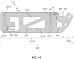
- central part 210 may comprise an attachment region 210-1 to a motorized device such as a walking assistance device according to the present invention as well as a support region 210-2.
- the attachment region 210-1 may consist of a longitudinal extension of the support region 210-2 and may comprise a plurality of housings, such as for example a plurality of screw threads, adapted to receive fixing elements, such as by way of non-limiting example a plurality of screws, making it possible to connect the electronic handle 210 to the walking assistance device.
- the support region 210-2 is adapted to allow a user to lean on it when the user interacts with the motorized device or the walking assistance apparatus. Thus, in this embodiment, it is the central portion 210 which directly undergoes a deformation when a force is applied by the user.
- the support region 210-2 of the central part 210 may advantageously comprise at least one embedded beam and a deformation bridge.
- the embedded beam advantageously comprises a embedded end 211-2, 211-3 and a free end 211-1, 211-4.
- the embedded end 211-2, 211-3 is connected to the central part while the free end 211-1, 211-4 has a degree of freedom allowing a movement of said free end when a force is applied to the electronic handle 200.
- the embedded beams are arranged so as to have a degree of freedom when a force F2 is applied according to a first component but not to have a degree of freedom when a force F2 is applied according to a second component perpendicular to the first component.
- the free end 211-1, 211-4 may have a degree of freedom along a specific axis such as the axis of one of the components of the applied force. This thus makes it possible to generate a displacement of the free end 211-1, 211-4 only if the applied force has a given non-zero component.
- the free end 211-1, 211-4 may have a degree of freedom authorizing a displacement of said free end along the axis of the second component of the applied force, said second component of the applied force possibly corresponding to a horizontal component F2.
- the support region 210-2 of the central part 210 can advantageously comprise at least two embedded beams, preferably arranged at the ends, along a longitudinal axis, of the central part 210.
- a deformation bridge of the central part 210 may comprise a through opening 212 opening onto a recess 213.
- the through opening 212 is arranged to be able to undergo elastic deformation when a force is applied to the electronic handle 200. More particularly, the volume of the through opening 212 may increase or decrease depending on the application of the force to the electronic handle 200.
- the through opening 212 can be arranged so that its volume varies only when a force comprising a particular component is applied. This makes it possible to generate an increase or a decrease in the volume of the through opening 212, by a displacement of the central part 210 and more particularly of the support region 210-2, only if the applied force has a given non-zero component (e.g. vertical component).
- a non-zero component e.g. vertical component
- the increase or decrease in the volume of the through opening 212 may be generated along a specific axis of an applied force, such as the axis of one of the components of the applied force.
- the through opening 212 may be arranged so as to allow a displacement of the support region 210-2, and therefore an increase or decrease in the volume of the through opening 212 along the axis of the first component of the applied force, said first component of the applied force possibly corresponding to a vertical component F1.
- the second photoelectric cell 250 can be fixed to the central part 210, within a suitable cavity.
- the second shutter element 260 will in this case be fixed directly to a free end 211-1, 211-4 of a recessed beam.
- the application of a force on the support region 210-2 if it is sufficient, will induce an elastic deformation of the central part 210.
- Such a deformation can be measured if the second component of the applied force is non-zero, leading to a modification of the quantity of photons received by the second receiver 252.
- the elastic deformation will lead to a displacement of the second shutter element 260 fixed to the free end 211-1, 211-4 along the axis of the second component of the applied force, thus blocking all or part of the light beam received by the receiver 252 and generated by the diode 251.
- the first photoelectric cell 230 and the first shutter element 240 can respectively be positioned on either side of the through opening 212 of the deformation bridge. Indeed, the application of a force to the support region 210-2, if it is sufficient, will induce an elastic deformation of the central part 210. Such a deformation can be measured if the first component of the applied force is non-zero, leading to a modification of the quantity of photons received by the first receiver 232.
- the elastic deformation will cause a displacement of the first shutter element 240 fixed on the central part 210, more particularly in a suitable housing 214, along the axis of the first component of the applied force, thus blocking all or part of the light beam received by the receiver 232 and generated by the diode 231.
- the central part 210 may comprise at least two central openings 216-1, 216-2 traversed by a portion 215 of the central part, said central openings being positioned between the at least one embedded beam 211-2, 211-3 and the deformation bridge.
- the central part 210 comprises two embedded beams 211-2, 211-3, the two central openings 216-1, 216-2 are positioned between said embedded beams.
- Such prestresses can generate an elastic deformation of the deformation bridge and potentially a modification of the quantity of photons received by the first receiver 232.
- each of the electronic handles 200 may comprise an outer casing 220, said outer casing 220 being coupled and/or fixed to the central part 210.
- the outer casing 220 is not fixed to the central part 210 but is only coupled for example by one or more force transmission elements.
- one or more force transmission elements of the outer casing 220 are arranged so as to pass through a housing made in the free end 211-1, 211-4 of the embedded beam 211-2, 211-3.
- a force transmission element may for example correspond to a screw, a tube, a cylinder, such as a pin connecting the two parts of the outer casing 220 and passing through the central part 210 in housings made in the free end 211-1, 211-4 of the embedded beam 211-2, 211-3.
- the force transmission element is not in direct or indirect contact with the central part.
- the housing made in the free end 211-1, 211-4 of the embedded beam 211-2, 211-3 comprises an element, such as a pin, having a clearance fit.
- the outer casing 220 preferably transmits the external forces to the central part 210 by the pins passing through the central part in its parts 211-1 and 211-4, having a clearance fit.
- the pins may correspond to metal cylinders passing through the central part 210 at the free end 211-1 and 211-4 and being housed in the outer part 220.
- Such a force transmission element makes it possible to avoid torsional forces which can interfere with measurements when a user applies a force.
- Such an arrangement makes it possible to improve the accuracy of the measurement and in particular its linearity.
- the handle may also include a fastening element such as a screw passing through the central part 210 in the cavities 216-1 and 216-2.
- the force applied by a hand on the handle can be modeled by a force, F, in the sagittal plane, having a vertical component, F1, and a horizontal component, F2, in the direction of the user's walking.
- F a force in the sagittal plane
- F1 a vertical component
- F2 a horizontal component
- Such an electronic handle makes it possible to ignore the compressions made by the user when using the handle to focus on actions involving a force associated with a given direction.
- a motorized walker 1 according to the invention is configured so as to be able to be controlled intuitively by a user.
- a motorized walker 1 according to the invention is configured so that at least one movement motor 20 and at least one verticalization motor 30 can be controlled by a user from a manipulation of the electronic handles.
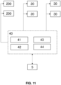
- At least one of the electronic handles 200 comprises a sensor coupled, preferably operatively, to a control module 40 and the control module 40 is configured so as to be able to control the verticalization motor 30 and the movement motor 20.
- the control module 40 will be able to control the verticalization motor 30 and the movement motor 20 according to values transmitted by the sensor of the electronic handle.
- the electronic handle 200 may comprise several sensors coupled, preferably functionally, to the control module 40.
- the coupling allows the sensor to transmit data to the control module.
- the functional coupling of one or more sensors of one of the electronic handles 200 to the control module may correspond to a transmission of information, such as current values (intensity or voltage) from the sensors to the control module, directly or indirectly.
- this functional coupling may include a fusion of the information coming from the sensors so that the control module can give an instruction to one or more motors according to values coming from several sensors.
- Such a sensor fusion makes it possible, for example, to detect the user's intention to get up in order to synchronize the movement of the walker with the movement of the human.
- the electronic handle 200 Since the electronic handle 200 is equipped with sensors and electronics, it is necessary to bring cables from the location of the electronics on the chassis.
- the cables are for example integrated into a jack of a verticalization ramp.
- a cable chain is placed inside the jack tube. This solution allows the complete integration of the cables inside the mechanism and protects the cables from the rotating screw and the passage of the nut and the external guide.
- the cable chain allows a ribbon of 5 wires with a pitch of 0.8 mm to circulate from the fixing of the handle to the location of the system control electronics.
- the senor of the electronic handle 200 is arranged so as to be able to measure at least one component of a force applied to the electronic handle 200.
- the sensor of the electronic handle 200 may be any device arranged and configured to measure the value of a force or effort.
- a sensor of the electronic handle 200 may be selected from: a force sensor, a pressure sensor, a barrier photoelectric cell, a displacement sensor.
- the sensor of the electronic handle 200 may comprise a strain gauge, a resistive force sensor or a photoelectric cell.
- the electronic handle 200 according to the invention comprises at least one photoelectric cell 230.
- control module 40 may comprise one or more processors 41.
- the control module 40 may advantageously be configured to cooperate with the sensors, collect the data measured by said sensors and calculate a value from said measured data. Such cooperation may in particular take the form of an internal communication bus.
- control module 40 is configured to further calculate a force variation value applied to the electronic handle over a time interval and trigger a movement of the electronic handles when the calculated applied force variation value is greater than a predetermined force variation value.
- the motorized walker 1 can perform a verticalization adapted to the individual at a time desired by the individual without the latter having to perform any other action than to lean on the electronic handles as when he wishes to stand up by leaning on a table for example.
- control module 40 is configured to further calculate a force value applied to the electronic handle and to trigger a verticalization only if the calculated applied force value to the electronic handle at the start of the time interval is less than or equal to a predetermined force value.
- the processor 41 is advantageously configured to trigger a verticalization when the measured proximity value is greater than a predetermined proximity value.
- control module 40 may comprise a data memory 42.
- the data memory 42 may advantageously comprise a non-erasable section, physically isolated or simply arranged so that write or erase access is prohibited.
- the data memory may further be arranged to record the data measured by the sensors present on a motorized walker.
- the data memory 42 may further comprise one or more programs, or more generally one or more sets of program instructions, said program instructions being intelligible by the processor 41. The execution or interpretation of said instructions by said processor causes the implementation of a method for controlling a motorized walker 1 according to the invention.
- the data memory 42 is configured to store a minimum height and a maximum height of the electronic handles on each of the verticalization ramps 100.
- the minimum height is preferably between 400 cm and 600 cm from the ground and the maximum height is preferably between 900 cm and 1100 cm from the ground.
- the data memory 42 is advantageously configured to store threshold values that can be used when controlling the motorized walker 1 by a processor 41 or more generally by a control module 40. For example, a predetermined threshold value of applied force, a predetermined threshold value of applied force variation, and/or a predetermined proximity threshold value.
- the data memory 42 can further be configured to store a verticalization duration.
- control module 40 may comprise a communication module 43 ensuring communication between the different components of the control module 40, in particular according to a suitable wired or wireless communication bus.
- the communication module 43 is configured to ensure the communication of the data measured by the sensors of a motorized walker according to the invention to a data memory configured to record such data.
- the communication module also allows communication between the processor and the data memory in order in particular to calculate a value based on the stored data, said value can then be recorded directly in a suitable field in the data memory.
- the communication module also allows the processor to control a verticalization motor and a movement motor of a motorized walker, in particular a control of one or the other of the motors can be associated with a value calculated from the data measured by the sensors.
- each of the verticalization ramps 100 comprises a cable carrier chain allowing the establishment of a wired connection, direct or indirect, between at least one of the electronic handles and the verticalization motor and/or the movement motor.
- control module 40 may include a human-machine interface 44 .
- the human-machine interface can correspond to a screen, a printer, a communication port coupled to a computer device or any other interface allowing communication with a human, in a manner perceptible via one of his senses or a computer client via a communication link.
- Such an HMI can be used to configure the control module.
- the control module can interact via an HMI with other electronic devices or connected objects so as to collect parameter data.
- parameter data can for example correspond to maximum height and/or minimum height values.
- a control at the electronic handles makes it possible to memorize, for example during the first use, the minimum and/or maximum height information.
- the HMI and more particularly the electronic handles linked to the control module are configured to detect the user's intention (to stand up or sit down) and whether the user is still linked to the verticalizer (if for example there was a false start and the user did not stand up).
- a motorized walker 1 is equipped with an electrical power source (not shown in the figures) adapted to enable the various elements of said motorized walker to operate.
- a power source generally consists of a battery or a plurality of batteries arranged to deliver sufficient electrical energy to enable the operation of the various verticalization and movement motors or to ensure the operation of the various components of the control module.
- a motorized walker 1 according to the invention cannot be limited to a single control module 40; it is provided, in a particular embodiment, that the motorized walker 1 comprises a control module dedicated to each handle. Each of the control modules can thus be arranged inside or outside the handle with which it is associated. In addition, the walker can comprise an electronic power card per motor which makes it possible to control the energy sent to said motor.
- the invention relates to a method 300 for controlling a motorized walker 1, preferably a motorized walker 1 according to the invention.
- a control method 300 according to an embodiment of the invention is illustrated in figure 12 .
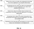
- a method 300 for controlling a motorized walker 1 comprises the steps of measuring 320 at least one force value applied to an electronic handle 200, comparing 330 the at least one force value applied to a predetermined force threshold value, and generating 370 a control instruction to at least one of the verticalization and movement motors.
- a method 300 for controlling a motorized walker 1 may comprise the steps of calibrating 310 the motorized walker, calculating 340 a value of variation over time of a force applied to an electronic handle 200, comparing 350 the value of variation over time of a force applied to a predetermined threshold value and determining 360 a position value of the at least one electronic handle 200.
- Storing such data allows the walker to be adapted to the physiognomy of a given user (e.g. height of the handles) and also to be adapted to their physiology (e.g. total verticalization time).
- these threshold values may have been pre-recorded in a data memory 42 during the design of the motorized walker 1.
- a method 300 for controlling a motorized walker comprises a step 320 of measuring at least one force value applied to an electronic handle 200.
- This measuring step 320 may correspond to the generation of a value of a component of a force applied to the electronic handle 200 by a user.
- the applied force whose value is measured corresponds to a vertical component of the applied force.
- the detection of the sitting-standing transfer movement is done at least in part by measuring the vertical support force on the electronic handles 200.
- this step can include the measurement 320 of at least two components of the force applied to the electronic handle 200. Furthermore, this measurement 320 can preferably be carried out for the two electronic handles 200.
- This step can be performed by one or more sensors of an electronic handle 200.
- a method 300 for controlling a motorized walker comprises a step 330 of comparing the at least one applied force value to a predetermined threshold value of applied force. Such a comparison makes it possible to generate a user posture indicator. For example, the comparison step may lead to generating a binary value (e.g. yes/no).
- a method according to the invention will be able to advantageously detect a user's posture and in particular their ability or need to move from a seated position to standing by the detection of an exceedance of a threshold value by a measured value of applied force.
- This comparison step may also include the generation of a posture indicator in the form of an alphanumeric value or a numerical value.
- a numerical value may for example correspond to a difference between the measured value and the predetermined threshold value.
- a posture indicator value may advantageously be used in combination with other values when generating a control instruction.
- This step can be performed by a control module 40 and in particular by a processor 41 configured to perform such a comparison and generate the user's posture indicator.
- a method 300 for controlling a motorized walker 1 may advantageously include a step 340 of calculating a value of variation over time of a force applied to an electronic handle 200.
- This step can be carried out by a control module 40 of a motorized walker 1 and more particularly by a processor 41 of said control module 40.
- such a time variation value may correspond to a variation in force applied during a predetermined time interval.
- the time interval is preferably less than 1 second, more preferably less than 0.5 seconds, even more preferably less than 0.2 seconds.
- the method according to the invention makes it possible to monitor in real time the interactions of a user with a motorized walker to determine the intention thereof.
- This value can be calculated for an electronic handle 200 and preferably for the two electronic handles 200.
- the applied force whose temporal variation is calculated corresponds to a vertical component of the applied force.
- This calculated value can be used in a step 350 of comparing the time variation value of an applied force to a predetermined threshold value of applied force variation.
- Such a comparison makes it possible to generate a user intention indicator.
- the comparison step may lead to generating a binary value (eg yes/no).
- Such an intention index may in particular correspond to a posture transition intention indicator.
- This comparison step may also include the generation of an intention indicator in the form of an alphanumeric value or a numerical value.
- a numerical value may for example correspond to a difference between the calculated value and the predetermined threshold value.
- An intention indicator value may advantageously be used in combination with other values when generating a control instruction.
- the method according to the invention will advantageously be able to best characterize a user's intention to move from a sitting to a standing position.
- a detection threshold based on an applied force value preferably a vertical component value
- a detection threshold based on an applied force variation value allows for better control results and an increase in the specificity of the control.
- a method of controlling 300 a motorized walker may also comprise a step of determining 360 a position value of the at least one electronic handle 200.
- a position sensor preferably positioned at the level of a verticalization ramp 100 or an electronic handle 200, may be configured to determine the position of the handle. This position value of the electronic handle may advantageously be used in combination with other values when generating a control instruction.
- This step can be carried out by a control module 40 and more particularly a processor 41 configured to determine such a position value from the data provided by a suitable sensor.
- a method 300 for controlling a motorized walker may also include a step of determining a proximity value between the trunk of a user of the motorized walker 1 and a proximity sensor 50.
- a proximity sensor may determine the distance between the user and said proximity sensor. This distance value or a position index of the user derived from such a distance value may advantageously be used in combination with other values when generating a control instruction.
- This step can be carried out by a control module 40 and more particularly a processor 41 configured to determine the distance separating a user from a proximity sensor positioned on the motorized walker 1, from the data provided by said proximity sensor.
- a method 300 for controlling a motorized walker may also comprise a step 370 for generating a control instruction to at least one of the verticalization motors 30 and the movement motors 20.
- this step of generating a control instruction may be carried out on the basis of the measured value of force applied to an electronic handle or on a posture index value.
- the control instruction may be a function of the comparison of at least one applied force value with a predetermined threshold value of applied force.
- the generation 370 of a control instruction may also take into account other parameters. Preferably, it takes into account the measured value of force applied to an electronic handle or the posture index value in combination with the temporal variation value of a force applied to an electronic handle or the intention index value.
- control instruction may also take into account the position index value or the measured distance value of the user relative to the proximity sensor.
- This step can be carried out by a control module 40 of a motorized walker 1 and more particularly by a processor 41 of said control module.
- control method 300 advantageously makes it possible to generate 470 a control instruction to at least one movement motor 20 and/or verticalization motor 30.
- a method according to the invention comprises a measurement 420 of at least one value of the horizontal component of the force applied to an electronic handle 200.
- This measurement step 420 may correspond to the generation of a value of a horizontal component of a force applied to the electronic handle 200 by a user.
- the detection of an intention of a given user to advance the walker is done at least in part by measuring the horizontal support force on one or two electronic handles 200.
- this step can include measuring at least two components of the force applied to the electronic handle 200.
- this measurement 420 can preferably be carried out for the two electronic handles 200.
- a method 300 for controlling a motorized walker may then comprise a step 430 of comparing the at least one horizontal component value of the force applied to an electronic handle to a predetermined threshold value of applied force.
- a comparison makes it possible to generate a user movement indicator.
- the comparison step may lead to generating a binary value (e.g. yes/no).
- the method according to the invention may advantageously detect a movement initiated by a user and in particular his intention to advance the motorized walker 1 by detecting an exceeding of a threshold value by a measured value of applied force.
- This comparison step may include the generation of a displacement indicator in the form of an alphanumeric value or a numerical value.
- a numerical value may for example correspond to a difference between the measured value and the predetermined threshold value.
- a displacement indicator value may advantageously be used in combination with other values when generating a control instruction.
- This comparison step 430 can be carried out by a control module 40 and more particularly a processor 41 configured to determine a user movement indicator, from one or more values of one or more components of the force applied to an electronic handle 200 measured by a sensor arranged in said handle.
- a method 300 for controlling a motorized walker may advantageously include a step 440 of calculating a value of variation over time of a horizontal component of force applied to an electronic handle 200.
- such a time variation value may correspond to a variation of the force applied during a predetermined time interval.
- the time interval is preferably less than 1 second, more preferably less than 0.5 seconds, even more preferably less than 0.2 seconds.
- said calculation step 440 may be carried out by a control module 40 of a motorized walker 1 and more particularly by a processor 41 of said control module.
- This calculated value can be used in a comparison step 450 of the temporal variation value of a horizontal component of applied force to a predetermined threshold value of variation of a horizontal component of applied force.
- Such a comparison makes it possible to generate a user speed indicator.
- the comparison step may lead to generating a binary value (e.g. yes/no).
- a speed index may in particular correspond to a speed intention.
- This comparison step may also include the generation of a speed indicator in the form of an alphanumeric value or a numerical value.
- a numerical value may for example correspond to a difference between the calculated value and the predetermined threshold value.
- a speed indicator value may advantageously be used in combination with other values when generating a control instruction.
- the method according to the invention may advantageously best characterize the intention of a user to move by means of the motorized walker 1.
- certain parameters of the walker such as the maximum height of the electronic handles, the speed of verticalization, or the threshold for initiating verticalization or that for returning to the low position can be adapted by learning.
- the learning can be supervised or unsupervised learning.
- the walker is capable of implementing algorithms based on supervised or unsupervised learning methods.
- the walker is configured to train and implement one or more algorithms. These algorithms may have been constructed from different learning models, in particular partitioning, supervised or unsupervised.
- the algorithm can be derived from the use of a supervised statistical learning model selected for example from kernel methods (e.g.
- a method of controlling a motorized walker may also comprise a step 470 of generating a control instruction to at least one movement motor 20.
- this step of generating a control instruction control can be performed on the basis of the measured value of the horizontal component of force applied to an electronic handle or on a displacement index value.
- the control instruction can be a function of the comparison of at least one applied force value with a predetermined threshold value of applied force.
- the generation 470 of a control instruction can also take into account other parameters. Preferably, it takes into account the measured value of the horizontal component of force applied to an electronic handle or the displacement index value in combination with the temporal variation value of the horizontal component of a force applied to an electronic handle or the speed index value.
- the control instruction can also be generated so as to minimize the jolt associated with the movement of the motorized walker 1.
- a motorized walker 1 according to the invention or a control method 300 according to the invention allow intuitive control of a walker by a user generally in a situation of motor deficiency in his lower limbs.
- a user will be able to control the means (i.e. ramp) of verticalization 30 (i.e. verticalization motor) to help him move from a seated position to a standing position on the one hand and control the movement means 20 (i.e. movement motor) of the motorized walker after the latter has helped him move to the standing position.
Landscapes
- Health & Medical Sciences (AREA)
- Life Sciences & Earth Sciences (AREA)
- Animal Behavior & Ethology (AREA)
- General Health & Medical Sciences (AREA)
- Public Health (AREA)
- Veterinary Medicine (AREA)
- Epidemiology (AREA)
- Pain & Pain Management (AREA)
- Physical Education & Sports Medicine (AREA)
- Rehabilitation Therapy (AREA)
- Rehabilitation Tools (AREA)
Claims (15)
- Motorisierte Gehhilfe (1) mit einem Rahmen (10), der einen vorderen Teil (10a) und einen hinteren Teil (10b) aufweist, worin ein Paar Räder (11) angeordnet ist, um den hinteren Teil (10b) des Rahmens (10) zu tragen, und mindestens ein Rad (12) angeordnet ist, um den vorderen Teil des Rahmens zu tragen, worin mindestens eines der Räder mit einem Fortbewegungsmotor (20) gekoppelt ist, worin- der Rahmen (10) mit zwei Aufrichtungsrampen (100) versehen ist, worin die Aufrichtungsrampen (100) eine Längsachse aufweisen, die mit einer senkrecht zum Boden stehenden Achse einen Winkel zwischen 20° und 40° bildet, worin jede der Aufrichtungsrampen (100) mit einem elektronischen Griff (200) verbunden ist, der entlang der Aufrichtungsrampe (100), mit der er verbunden ist, translatorisch beweglich ist,- dieser mindestens einen Aufrichtungsmotor (30) umfasst, der so angeordnet ist, dass er eine synchrone Bewegung der elektronischen Griffe (200) entlang der Aufrichtungsrampen (100) ermöglicht, worin diese Bewegung geeignet ist, einen Benutzer der Gehhilfe von einer sitzenden in eine stehende Position zu bringen,- mindestens einer der elektronischen Griffe (200) mindestens zwei Sensoren umfasst, die funktionell mit einem Steuermodul (40) gekoppelt sind, von denen einer ausgestaltet ist, eine horizontale Komponente und der andere eine vertikale Komponente einer Kraft zu messen, die vom Benutzer auf den elektronischen Griff ausgeübt wird, worin das Steuermodul (40) ausgestaltet ist, den Aufrichtungsmotor (30) und den Fortbewegungsmotor (20) zu steuern, und worin der Aufrichtungsmotor (30) und der Fortbewegungsmotor (20) in Abhängigkeit von Werten gesteuert werden, die von den Sensoren des elektronischen Griffs (200) übertragen werden, worin das Steuermodul (40) konfiguriert ist, einen Intentionsindex und einen Bewegungsindikator eines Benutzers der Gehhilfe zu berechnen, die einer Interaktion des Benutzers mit der Gehhilfe entsprechen, worin der Intentionsindex teilweise aus dem Wert der Messung der vertikalen Komponente und der Bewegungsindikator zumindest teilweise aus dem Wert der Messung der horizontalen Komponente der ausgeübten Kraft berechnet wird.
- Motorisierte Gehhilfe (1) nach Anspruch 1, dadurch gekennzeichnet, dass die Berechnung des Intentionsindex eines Benutzers der Gehhilfe zusätzlich ein Vorhersagemodell verwendet, das aus Daten trainiert wird, die von den Sensoren der elektronischen Griffe (200) während der Benutzung der motorisierten Gehhilfe (1) durch den Benutzer erzeugt werden.
- Motorisierte Gehhilfe (1) nach einem der Ansprüche 1 oder 2, dadurch gekennzeichnet, dass das Steuermodul (40) ausgestaltet ist, außerdem anhand von Daten, die von den Sensoren der elektronischen Griffe (200) erzeugt werden, zu bestimmen, ob ein Benutzer der Gehhilfe auf der Gehhilfe steht und sich auf ihr abstützt.
- Motorisierte Gehhilfe (1) nach einem der Ansprüche 1 bis 3, dadurch gekennzeichnet, dass jede der Aufrichtungsrampen (100) ein motorisiertes Schrauben-Mutter-System aufweist, das durch den Aufrichtungsmotor (30) angetrieben wird und die Bewegung der elektronischen Griffe (200) entlang der Aufrichtungsrampen (100) ermöglicht.
- Motorisierte Gehhilfe (1) nach einem der Ansprüche 1 bis 4, dadurch gekennzeichnet, dass die Aufrichtungsrampen (100) ein Lager aufweisen, das bezüglich eines Schrauben-Mutter-Systems auf der gegenüberliegenden Seite des Aufrichtungsmotor (30) liegt.
- Motorisierte Gehhilfe (1) nach einem der Ansprüche 1 bis 5, dadurch gekennzeichnet, dass die elektronischen Griffe (200) und die Aufrichtungsrampen (100) über ein innenliegendes Führungssystem gekoppelt sind, worin das Führungssystem innerhalb der Aufrichtungsrampen (100) angeordnet ist.
- Motorisierte Gehhilfe (1) nach einem der Ansprüche 1 bis 5, dadurch gekennzeichnet, dass die elektronischen Griffe (200) und die Aufrichtungsrampen (100) über ein äußeres Führungssystem gekoppelt sind, worin das Führungssystem außerhalb der Aufrichtungsrampen (100) angeordnet ist.
- Motorisierte Gehhilfe (1) nach einem der Ansprüche 1 bis 7, dadurch gekennzeichnet, dass diese zwei Aufrichtungsmotoren (30) aufweist, die jeweils mit einer der Aufrichtungsrampen (100) gekoppelt und vorzugsweise an einem Ende der Aufrichtungsrampe (100) angeordnet sind.
- Motorisierte Gehhilfe (1) nach einem der Ansprüche 1 bis 8, dadurch gekennzeichnet, dass diese einen Datenspeicher (42) umfasst, worin der Datenspeicher ausgestaltet ist, eine minimale Höhe und eine maximale Höhe der elektronischen Griffe an jeder der Aufrichtungsrampen (100) zu speichern.
- Motorisierte Gehhilfe (1) nach einem der Ansprüche 1 bis 9, dadurch gekennzeichnet, dass die Sensoren ausgewählt sind unter einem Kraftsensor, einem Drucksensor, einer Einweg-Fotozelle und einem Bewegungssensor.
- Motorisierte Gehhilfe nach einem der Ansprüche 1 bis 10, dadurch gekennzeichnet, dass das Steuermodul (40) ausgestaltet ist, zusätzlich einen Kraftänderungswert zu berechnen, der über ein Zeitintervall auf den elektronischen Griff (200) ausgeübt wird, und eine Bewegung der elektronischen Griffe auslöst, wenn der berechnete Wert der ausgeübten Kraftänderung größer als ein bestimmter Kraftänderungswert ist.
- Motorisierte Gehhilfe (1) nach einem der Ansprüche 1 bis 11, dadurch gekennzeichnet, dass das Steuermodul (40) ausgestaltet ist, zusätzlich einen Wert der auf den elektronischen Griff (200) ausgeübten Kraft zu berechnen und eine Aufrichtung nur dann auszulösen, wenn der Wert der auf den elektronischen Griff ausgeübten Kraft größer oder gleich einem bestimmten Kraftwert ist.
- Motorisierte Gehhilfe (1) nach einem der Ansprüche 1 bis 12, dadurch gekennzeichnet, dass diese einen Näherungssensor (50) aufweist, der ausgestaltet ist, einen Näherungswert zwischen dem Rumpf eines Benutzers der Gehhilfe und dem Rahmen zu messen, und dass das Steuermodul (40) außerdem ausgestaltet ist, eine Aufrichtung auszulösen, wenn der gemessene Näherungswert größer als ein bestimmter Näherungswert ist.
- Motorisierte Gehhilfe (1) nach einem der Ansprüche 1 bis 13, dadurch gekennzeichnet, dass das Steuermodul (40) ferner ausgestaltet ist, mindestens einen Aufrichtungsmotor (30) so zu steuern, dass der Ruck beim Aufsteigen minimiert wird, und die Position der elektronischen Griffe (200) während des Aufsteigens so steuert, dass ihre Position X(t) der folgenden Gleichung entspricht:
 X(t) die Position des elektronischen Griffs auf einer vertikalen Achse relativ zu einer niedrigsten Position Xi als Funktion der Zeit t ist;Xf eine maximale Höhe des elektronischen Griffs ist; undT eine Gesamtzeit für die Aufrichtung ist.
 - Verfahren (300) zur Steuerung einer motorisierten Gehhilfe (1) nach einem der Ansprüche 1 bis 14, worin das Steuerungsverfahren die Schritte umfasst:- Messen (320), durch die Sensoren von mindestens einem der elektronischen Griffe (200), von mindestens einem Kraftwert, der auf den elektronischen Griff (200) ausgeübt wird,- Vergleichen (330) des mindestens einen Kraftwerts mit einem bestimmten Schwellenwert für die ausgeübte Kraft durch das Steuermodul (40), und- Erzeugen (370), durch das Steuermodul (40), eines Steuerbefehls an den mindestens einen der Motoren zum Aufrichten (30) und Bewegen (20) in Abhängigkeit von der ermittelten Position des mindestens einen elektronischen Griffs (200) und dem gemessenen Wert der ausgeübten Kraft.
Applications Claiming Priority (2)
| Application Number | Priority Date | Filing Date | Title |
|---|---|---|---|
| FR1910307A FR3100713B1 (fr) | 2019-09-18 | 2019-09-18 | Déambulateur motorisé et procédé de contrôle associé |
| PCT/FR2020/051631 WO2021053311A1 (fr) | 2019-09-18 | 2020-09-18 | Déambulateur motorisé et procédé de contrôle associé |
Publications (3)
| Publication Number | Publication Date |
|---|---|
| EP4031089A1 EP4031089A1 (de) | 2022-07-27 |
| EP4031089B1 true EP4031089B1 (de) | 2024-11-27 |
| EP4031089C0 EP4031089C0 (de) | 2024-11-27 |
Family
ID=68987938
Family Applications (1)
| Application Number | Title | Priority Date | Filing Date |
|---|---|---|---|
| EP20785550.3A Active EP4031089B1 (de) | 2019-09-18 | 2020-09-18 | Motorisierter gehwagen und zugehöriges steuerungsverfahren |
Country Status (8)
| Country | Link |
|---|---|
| US (1) | US20220347041A1 (de) |
| EP (1) | EP4031089B1 (de) |
| JP (1) | JP2022549801A (de) |
| KR (1) | KR20220085775A (de) |
| AU (1) | AU2020347902A1 (de) |
| CA (1) | CA3151556A1 (de) |
| FR (1) | FR3100713B1 (de) |
| WO (1) | WO2021053311A1 (de) |
Families Citing this family (1)
| Publication number | Priority date | Publication date | Assignee | Title |
|---|---|---|---|---|
| WO2025053894A1 (en) * | 2023-09-08 | 2025-03-13 | Massachusetts Institute Of Technology | Systems and methods for supporting a user |
Family Cites Families (18)
| Publication number | Priority date | Publication date | Assignee | Title |
|---|---|---|---|---|
| US4201338A (en) * | 1976-06-14 | 1980-05-06 | Emhart Zurich S. A. | Mold identification |
| US5411044A (en) * | 1994-04-12 | 1995-05-02 | Andolfi; Alexander S. | Patient transfer walker |
| US6092247A (en) * | 1998-10-02 | 2000-07-25 | Wilson; Harold R. | Powered patient lift vehicle |
| WO2008096210A1 (en) | 2007-02-10 | 2008-08-14 | Roy Rodetsky | Powered mobile lifting, gait training and omnidirectional rolling apparatus and method |
| US8770212B2 (en) * | 2011-06-20 | 2014-07-08 | Ahmad AlSayed M. Alghazi | Method of operation of a portable multifunctional mobility aid apparatus |
| US9433552B2 (en) * | 2013-01-17 | 2016-09-06 | Lg Electronics Inc. | Electric walking assistant device |
| WO2014122751A1 (ja) * | 2013-02-07 | 2014-08-14 | 富士機械製造株式会社 | 移動補助ロボット |
| US9523983B2 (en) * | 2015-04-08 | 2016-12-20 | Peter Chamberlain | Automated ambulatory rehabilitation device |
| NL2014986B1 (en) * | 2015-06-18 | 2017-01-23 | Filigrade B V | Waste separation method. |
| DE102016201743B3 (de) * | 2016-02-04 | 2017-04-06 | Kuka Roboter Gmbh | Mobilitätsassistenzvorrichtung |
| US9770380B1 (en) * | 2016-05-03 | 2017-09-26 | Susan Helane Dalton | Self propelled walker |
| DE102016217078A1 (de) * | 2016-09-08 | 2018-03-08 | Robert Bosch Gmbh | Verfahren zum Steuern einer Gehhilfe, Steuereinrichtung für eine Gehhilfe, Gehhilfe |
| WO2018222257A1 (en) | 2017-06-02 | 2018-12-06 | Ohio State Innovation Foundation | Active robotic walker and associated method |
| FR3073393B1 (fr) | 2017-11-13 | 2023-07-21 | Gema Sa | Dispositif d'assistance a la verticalisation |
| EP3530253B1 (de) * | 2018-02-27 | 2021-06-02 | Jtekt Corporation | Gehhilfevorrichtung |
| JP7024498B2 (ja) * | 2018-02-27 | 2022-02-24 | 株式会社ジェイテクト | 歩行支援装置 |
| EP3530252B1 (de) * | 2018-02-27 | 2022-03-30 | Jtekt Corporation | Gehhilfevorrichtung |
| FR3100887B1 (fr) * | 2019-09-18 | 2021-11-19 | Gema Sa | Poignée électronique pour la mesure d’une composante de force |
-
2019
- 2019-09-18 FR FR1910307A patent/FR3100713B1/fr active Active
-
2020
- 2020-09-18 CA CA3151556A patent/CA3151556A1/fr not_active Abandoned
- 2020-09-18 JP JP2022517871A patent/JP2022549801A/ja active Pending
- 2020-09-18 WO PCT/FR2020/051631 patent/WO2021053311A1/fr not_active Ceased
- 2020-09-18 US US17/760,986 patent/US20220347041A1/en not_active Abandoned
- 2020-09-18 KR KR1020227012839A patent/KR20220085775A/ko not_active Abandoned
- 2020-09-18 EP EP20785550.3A patent/EP4031089B1/de active Active
- 2020-09-18 AU AU2020347902A patent/AU2020347902A1/en not_active Abandoned
Also Published As
| Publication number | Publication date |
|---|---|
| CA3151556A1 (fr) | 2021-03-25 |
| AU2020347902A1 (en) | 2022-05-12 |
| FR3100713B1 (fr) | 2022-11-25 |
| US20220347041A1 (en) | 2022-11-03 |
| EP4031089C0 (de) | 2024-11-27 |
| EP4031089A1 (de) | 2022-07-27 |
| WO2021053311A1 (fr) | 2021-03-25 |
| KR20220085775A (ko) | 2022-06-22 |
| JP2022549801A (ja) | 2022-11-29 |
| FR3100713A1 (fr) | 2021-03-19 |
Similar Documents
| Publication | Publication Date | Title |
|---|---|---|
| EP4076331B1 (de) | Roboterisierte gehhilfe und zugehöriges verfahren zum vorbeugen von stürzen | |
| EP3152080B1 (de) | Ladesockel für eine batterie und verfahren zur verwendung des ladesockels | |
| EP2851055B1 (de) | Manuell angetriebenes Fahrzeug | |
| EP3697304B1 (de) | Vorrichtung zur messung der muskelkontraktionen und / oder muskelentspannung und zugehörige verfahren | |
| EP4031089B1 (de) | Motorisierter gehwagen und zugehöriges steuerungsverfahren | |
| WO2012010783A1 (fr) | Outil d'insertion d'objets tubulaires fins dans la cochlée | |
| FR2476456A1 (fr) | Dispositif pour determiner une pointure de chaussure correspondant a un pied | |
| FR3001450A1 (fr) | Dispositif d'aide a la montee et/ou a la descente de personne | |
| EP4031092B1 (de) | Motorisierte vorrichtung zur unterstützung beim gehen und verfahren zur steuerung dieser hilfsvorrichtung mit einem elektronischen handgriff | |
| EP3817972A1 (de) | Steuerungssystem für ein hybridfahrrad und mit einem solchen steuersystem ausgerüstetes hybridfahrrad | |
| WO2015082492A1 (fr) | Poignee pour un dispositif d'entrainement cognitif et dispositif d'entrainement cognitif la comprenant | |
| FR3048386B1 (fr) | Procede de recharge d’une batterie d’un vehicule mobile par une fiche de rechargement | |
| EP2355766A1 (de) | Vorrichtung zur kontrolle eines operationstisches | |
| FR3140261A1 (fr) | Procédé de commande d’une prothèse bionique de membre inférieur | |
| Pichon et al. | Artificial Intelligence methods to help measure sensory disorders: approaches and perspectives | |
| WO2007101951A1 (fr) | Appareil de mesures corporelles a lecture directe | |
| FR3144499A1 (fr) | Présentoir d’assistance pour applicateur cosmétique configure pour des utilisateurs ayant une mobilité limitée | |
| FR3136253A1 (fr) | Système de commande pour ouvrant de véhicule automobile | |
| FR3159103A1 (fr) | Dispositif d’aide à l’entraînement physique | |
| FR3048518A1 (fr) | Procede de positionnement d'un objet sur un support | |
| WO2019175653A1 (fr) | Fauteuil roulant |
Legal Events
| Date | Code | Title | Description |
|---|---|---|---|
| STAA | Information on the status of an ep patent application or granted ep patent |
Free format text: STATUS: UNKNOWN |
|
| STAA | Information on the status of an ep patent application or granted ep patent |
Free format text: STATUS: THE INTERNATIONAL PUBLICATION HAS BEEN MADE |
|
| PUAI | Public reference made under article 153(3) epc to a published international application that has entered the european phase |
Free format text: ORIGINAL CODE: 0009012 |
|
| STAA | Information on the status of an ep patent application or granted ep patent |
Free format text: STATUS: REQUEST FOR EXAMINATION WAS MADE |
|
| 17P | Request for examination filed |
Effective date: 20220418 |
|
| AK | Designated contracting states |
Kind code of ref document: A1 Designated state(s): AL AT BE BG CH CY CZ DE DK EE ES FI FR GB GR HR HU IE IS IT LI LT LU LV MC MK MT NL NO PL PT RO RS SE SI SK SM TR |
|
| DAV | Request for validation of the european patent (deleted) | ||
| DAX | Request for extension of the european patent (deleted) | ||
| 19U | Interruption of proceedings before grant |
Effective date: 20230111 |
|
| 19W | Proceedings resumed before grant after interruption of proceedings |
Effective date: 20240502 |
|
| RAP3 | Party data changed (applicant data changed or rights of an application transferred) |
Owner name: ATEK |
|
| GRAP | Despatch of communication of intention to grant a patent |
Free format text: ORIGINAL CODE: EPIDOSNIGR1 |
|
| STAA | Information on the status of an ep patent application or granted ep patent |
Free format text: STATUS: GRANT OF PATENT IS INTENDED |
|
| INTG | Intention to grant announced |
Effective date: 20240626 |
|
| GRAS | Grant fee paid |
Free format text: ORIGINAL CODE: EPIDOSNIGR3 |
|
| GRAA | (expected) grant |
Free format text: ORIGINAL CODE: 0009210 |
|
| STAA | Information on the status of an ep patent application or granted ep patent |
Free format text: STATUS: THE PATENT HAS BEEN GRANTED |
|
| AK | Designated contracting states |
Kind code of ref document: B1 Designated state(s): AL AT BE BG CH CY CZ DE DK EE ES FI FR GB GR HR HU IE IS IT LI LT LU LV MC MK MT NL NO PL PT RO RS SE SI SK SM TR |
|
| REG | Reference to a national code |
Ref country code: GB Ref legal event code: FG4D Free format text: NOT ENGLISH |
|
| REG | Reference to a national code |
Ref country code: CH Ref legal event code: EP |
|
| REG | Reference to a national code |
Ref country code: DE Ref legal event code: R096 Ref document number: 602020042124 Country of ref document: DE |
|
| REG | Reference to a national code |
Ref country code: IE Ref legal event code: FG4D Free format text: LANGUAGE OF EP DOCUMENT: FRENCH |
|
| U01 | Request for unitary effect filed |
Effective date: 20241220 |
|
| U07 | Unitary effect registered |
Designated state(s): AT BE BG DE DK EE FI FR IT LT LU LV MT NL PT RO SE SI Effective date: 20250117 |
|
| PG25 | Lapsed in a contracting state [announced via postgrant information from national office to epo] |
Ref country code: IS Free format text: LAPSE BECAUSE OF FAILURE TO SUBMIT A TRANSLATION OF THE DESCRIPTION OR TO PAY THE FEE WITHIN THE PRESCRIBED TIME-LIMIT Effective date: 20250327 Ref country code: HR Free format text: LAPSE BECAUSE OF FAILURE TO SUBMIT A TRANSLATION OF THE DESCRIPTION OR TO PAY THE FEE WITHIN THE PRESCRIBED TIME-LIMIT Effective date: 20241127 |
|
| PG25 | Lapsed in a contracting state [announced via postgrant information from national office to epo] |
Ref country code: ES Free format text: LAPSE BECAUSE OF FAILURE TO SUBMIT A TRANSLATION OF THE DESCRIPTION OR TO PAY THE FEE WITHIN THE PRESCRIBED TIME-LIMIT Effective date: 20241127 |
|
| PG25 | Lapsed in a contracting state [announced via postgrant information from national office to epo] |
Ref country code: NO Free format text: LAPSE BECAUSE OF FAILURE TO SUBMIT A TRANSLATION OF THE DESCRIPTION OR TO PAY THE FEE WITHIN THE PRESCRIBED TIME-LIMIT Effective date: 20250227 |
|
| PG25 | Lapsed in a contracting state [announced via postgrant information from national office to epo] |
Ref country code: GR Free format text: LAPSE BECAUSE OF FAILURE TO SUBMIT A TRANSLATION OF THE DESCRIPTION OR TO PAY THE FEE WITHIN THE PRESCRIBED TIME-LIMIT Effective date: 20250228 |
|
| PG25 | Lapsed in a contracting state [announced via postgrant information from national office to epo] |
Ref country code: PL Free format text: LAPSE BECAUSE OF FAILURE TO SUBMIT A TRANSLATION OF THE DESCRIPTION OR TO PAY THE FEE WITHIN THE PRESCRIBED TIME-LIMIT Effective date: 20241127 |
|
| PG25 | Lapsed in a contracting state [announced via postgrant information from national office to epo] |
Ref country code: RS Free format text: LAPSE BECAUSE OF FAILURE TO SUBMIT A TRANSLATION OF THE DESCRIPTION OR TO PAY THE FEE WITHIN THE PRESCRIBED TIME-LIMIT Effective date: 20250227 |
|
| PG25 | Lapsed in a contracting state [announced via postgrant information from national office to epo] |
Ref country code: SM Free format text: LAPSE BECAUSE OF FAILURE TO SUBMIT A TRANSLATION OF THE DESCRIPTION OR TO PAY THE FEE WITHIN THE PRESCRIBED TIME-LIMIT Effective date: 20241127 |
|
| PG25 | Lapsed in a contracting state [announced via postgrant information from national office to epo] |
Ref country code: SK Free format text: LAPSE BECAUSE OF FAILURE TO SUBMIT A TRANSLATION OF THE DESCRIPTION OR TO PAY THE FEE WITHIN THE PRESCRIBED TIME-LIMIT Effective date: 20241127 |
|
| PG25 | Lapsed in a contracting state [announced via postgrant information from national office to epo] |
Ref country code: CZ Free format text: LAPSE BECAUSE OF FAILURE TO SUBMIT A TRANSLATION OF THE DESCRIPTION OR TO PAY THE FEE WITHIN THE PRESCRIBED TIME-LIMIT Effective date: 20241127 |
|
| PLBE | No opposition filed within time limit |
Free format text: ORIGINAL CODE: 0009261 |
|
| STAA | Information on the status of an ep patent application or granted ep patent |
Free format text: STATUS: NO OPPOSITION FILED WITHIN TIME LIMIT |
|
| U20 | Renewal fee for the european patent with unitary effect paid |
Year of fee payment: 6 Effective date: 20250924 |
|
| 26N | No opposition filed |
Effective date: 20250828 |