EP4030539B1 - Rechargeable battery - Google Patents
Rechargeable battery Download PDFInfo
- Publication number
- EP4030539B1 EP4030539B1 EP22151348.4A EP22151348A EP4030539B1 EP 4030539 B1 EP4030539 B1 EP 4030539B1 EP 22151348 A EP22151348 A EP 22151348A EP 4030539 B1 EP4030539 B1 EP 4030539B1
- Authority
- EP
- European Patent Office
- Prior art keywords
- cap plate
- opening
- electrode
- rechargeable battery
- coating layer
- Prior art date
- Legal status (The legal status is an assumption and is not a legal conclusion. Google has not performed a legal analysis and makes no representation as to the accuracy of the status listed.)
- Active
Links
Images


Classifications
-
- H—ELECTRICITY
- H01—ELECTRIC ELEMENTS
- H01M—PROCESSES OR MEANS, e.g. BATTERIES, FOR THE DIRECT CONVERSION OF CHEMICAL ENERGY INTO ELECTRICAL ENERGY
- H01M50/00—Constructional details or processes of manufacture of the non-active parts of electrochemical cells other than fuel cells, e.g. hybrid cells
- H01M50/50—Current conducting connections for cells or batteries
- H01M50/571—Methods or arrangements for affording protection against corrosion; Selection of materials therefor
-
- H—ELECTRICITY
- H01—ELECTRIC ELEMENTS
- H01M—PROCESSES OR MEANS, e.g. BATTERIES, FOR THE DIRECT CONVERSION OF CHEMICAL ENERGY INTO ELECTRICAL ENERGY
- H01M10/00—Secondary cells; Manufacture thereof
- H01M10/04—Construction or manufacture in general
- H01M10/0422—Cells or battery with cylindrical casing
- H01M10/0427—Button cells
-
- H—ELECTRICITY
- H01—ELECTRIC ELEMENTS
- H01M—PROCESSES OR MEANS, e.g. BATTERIES, FOR THE DIRECT CONVERSION OF CHEMICAL ENERGY INTO ELECTRICAL ENERGY
- H01M10/00—Secondary cells; Manufacture thereof
- H01M10/04—Construction or manufacture in general
- H01M10/0431—Cells with wound or folded electrodes
-
- H—ELECTRICITY
- H01—ELECTRIC ELEMENTS
- H01M—PROCESSES OR MEANS, e.g. BATTERIES, FOR THE DIRECT CONVERSION OF CHEMICAL ENERGY INTO ELECTRICAL ENERGY
- H01M50/00—Constructional details or processes of manufacture of the non-active parts of electrochemical cells other than fuel cells, e.g. hybrid cells
- H01M50/10—Primary casings; Jackets or wrappings
- H01M50/102—Primary casings; Jackets or wrappings characterised by their shape or physical structure
- H01M50/109—Primary casings; Jackets or wrappings characterised by their shape or physical structure of button or coin shape
-
- H—ELECTRICITY
- H01—ELECTRIC ELEMENTS
- H01M—PROCESSES OR MEANS, e.g. BATTERIES, FOR THE DIRECT CONVERSION OF CHEMICAL ENERGY INTO ELECTRICAL ENERGY
- H01M50/00—Constructional details or processes of manufacture of the non-active parts of electrochemical cells other than fuel cells, e.g. hybrid cells
- H01M50/10—Primary casings; Jackets or wrappings
- H01M50/131—Primary casings; Jackets or wrappings characterised by physical properties, e.g. gas permeability, size or heat resistance
-
- H—ELECTRICITY
- H01—ELECTRIC ELEMENTS
- H01M—PROCESSES OR MEANS, e.g. BATTERIES, FOR THE DIRECT CONVERSION OF CHEMICAL ENERGY INTO ELECTRICAL ENERGY
- H01M50/00—Constructional details or processes of manufacture of the non-active parts of electrochemical cells other than fuel cells, e.g. hybrid cells
- H01M50/10—Primary casings; Jackets or wrappings
- H01M50/14—Primary casings; Jackets or wrappings for protecting against damage caused by external factors
- H01M50/141—Primary casings; Jackets or wrappings for protecting against damage caused by external factors for protecting against humidity
-
- H—ELECTRICITY
- H01—ELECTRIC ELEMENTS
- H01M—PROCESSES OR MEANS, e.g. BATTERIES, FOR THE DIRECT CONVERSION OF CHEMICAL ENERGY INTO ELECTRICAL ENERGY
- H01M50/00—Constructional details or processes of manufacture of the non-active parts of electrochemical cells other than fuel cells, e.g. hybrid cells
- H01M50/10—Primary casings; Jackets or wrappings
- H01M50/147—Lids or covers
- H01M50/148—Lids or covers characterised by their shape
- H01M50/153—Lids or covers characterised by their shape for button or coin cells
-
- H—ELECTRICITY
- H01—ELECTRIC ELEMENTS
- H01M—PROCESSES OR MEANS, e.g. BATTERIES, FOR THE DIRECT CONVERSION OF CHEMICAL ENERGY INTO ELECTRICAL ENERGY
- H01M50/00—Constructional details or processes of manufacture of the non-active parts of electrochemical cells other than fuel cells, e.g. hybrid cells
- H01M50/10—Primary casings; Jackets or wrappings
- H01M50/147—Lids or covers
- H01M50/148—Lids or covers characterised by their shape
- H01M50/154—Lid or cover comprising an axial bore for receiving a central current collector
-
- H—ELECTRICITY
- H01—ELECTRIC ELEMENTS
- H01M—PROCESSES OR MEANS, e.g. BATTERIES, FOR THE DIRECT CONVERSION OF CHEMICAL ENERGY INTO ELECTRICAL ENERGY
- H01M50/00—Constructional details or processes of manufacture of the non-active parts of electrochemical cells other than fuel cells, e.g. hybrid cells
- H01M50/10—Primary casings; Jackets or wrappings
- H01M50/147—Lids or covers
- H01M50/155—Lids or covers characterised by the material
- H01M50/164—Lids or covers characterised by the material having a layered structure
-
- H—ELECTRICITY
- H01—ELECTRIC ELEMENTS
- H01M—PROCESSES OR MEANS, e.g. BATTERIES, FOR THE DIRECT CONVERSION OF CHEMICAL ENERGY INTO ELECTRICAL ENERGY
- H01M50/00—Constructional details or processes of manufacture of the non-active parts of electrochemical cells other than fuel cells, e.g. hybrid cells
- H01M50/10—Primary casings; Jackets or wrappings
- H01M50/172—Arrangements of electric connectors penetrating the casing
- H01M50/174—Arrangements of electric connectors penetrating the casing adapted for the shape of the cells
- H01M50/181—Arrangements of electric connectors penetrating the casing adapted for the shape of the cells for button or coin cells
-
- H—ELECTRICITY
- H01—ELECTRIC ELEMENTS
- H01M—PROCESSES OR MEANS, e.g. BATTERIES, FOR THE DIRECT CONVERSION OF CHEMICAL ENERGY INTO ELECTRICAL ENERGY
- H01M50/00—Constructional details or processes of manufacture of the non-active parts of electrochemical cells other than fuel cells, e.g. hybrid cells
- H01M50/10—Primary casings; Jackets or wrappings
- H01M50/183—Sealing members
- H01M50/184—Sealing members characterised by their shape or structure
-
- H—ELECTRICITY
- H01—ELECTRIC ELEMENTS
- H01M—PROCESSES OR MEANS, e.g. BATTERIES, FOR THE DIRECT CONVERSION OF CHEMICAL ENERGY INTO ELECTRICAL ENERGY
- H01M50/00—Constructional details or processes of manufacture of the non-active parts of electrochemical cells other than fuel cells, e.g. hybrid cells
- H01M50/10—Primary casings; Jackets or wrappings
- H01M50/183—Sealing members
- H01M50/186—Sealing members characterised by the disposition of the sealing members
- H01M50/188—Sealing members characterised by the disposition of the sealing members the sealing members being arranged between the lid and terminal
-
- H—ELECTRICITY
- H01—ELECTRIC ELEMENTS
- H01M—PROCESSES OR MEANS, e.g. BATTERIES, FOR THE DIRECT CONVERSION OF CHEMICAL ENERGY INTO ELECTRICAL ENERGY
- H01M50/00—Constructional details or processes of manufacture of the non-active parts of electrochemical cells other than fuel cells, e.g. hybrid cells
- H01M50/10—Primary casings; Jackets or wrappings
- H01M50/183—Sealing members
- H01M50/19—Sealing members characterised by the material
- H01M50/191—Inorganic material
-
- H—ELECTRICITY
- H01—ELECTRIC ELEMENTS
- H01M—PROCESSES OR MEANS, e.g. BATTERIES, FOR THE DIRECT CONVERSION OF CHEMICAL ENERGY INTO ELECTRICAL ENERGY
- H01M50/00—Constructional details or processes of manufacture of the non-active parts of electrochemical cells other than fuel cells, e.g. hybrid cells
- H01M50/50—Current conducting connections for cells or batteries
- H01M50/528—Fixed electrical connections, i.e. not intended for disconnection
-
- H—ELECTRICITY
- H01—ELECTRIC ELEMENTS
- H01M—PROCESSES OR MEANS, e.g. BATTERIES, FOR THE DIRECT CONVERSION OF CHEMICAL ENERGY INTO ELECTRICAL ENERGY
- H01M50/00—Constructional details or processes of manufacture of the non-active parts of electrochemical cells other than fuel cells, e.g. hybrid cells
- H01M50/50—Current conducting connections for cells or batteries
- H01M50/531—Electrode connections inside a battery casing
- H01M50/533—Electrode connections inside a battery casing characterised by the shape of the leads or tabs
-
- H—ELECTRICITY
- H01—ELECTRIC ELEMENTS
- H01M—PROCESSES OR MEANS, e.g. BATTERIES, FOR THE DIRECT CONVERSION OF CHEMICAL ENERGY INTO ELECTRICAL ENERGY
- H01M50/00—Constructional details or processes of manufacture of the non-active parts of electrochemical cells other than fuel cells, e.g. hybrid cells
- H01M50/50—Current conducting connections for cells or batteries
- H01M50/531—Electrode connections inside a battery casing
- H01M50/536—Electrode connections inside a battery casing characterised by the method of fixing the leads to the electrodes, e.g. by welding
-
- H—ELECTRICITY
- H01—ELECTRIC ELEMENTS
- H01M—PROCESSES OR MEANS, e.g. BATTERIES, FOR THE DIRECT CONVERSION OF CHEMICAL ENERGY INTO ELECTRICAL ENERGY
- H01M50/00—Constructional details or processes of manufacture of the non-active parts of electrochemical cells other than fuel cells, e.g. hybrid cells
- H01M50/50—Current conducting connections for cells or batteries
- H01M50/543—Terminals
- H01M50/545—Terminals formed by the casing of the cells
-
- H—ELECTRICITY
- H01—ELECTRIC ELEMENTS
- H01M—PROCESSES OR MEANS, e.g. BATTERIES, FOR THE DIRECT CONVERSION OF CHEMICAL ENERGY INTO ELECTRICAL ENERGY
- H01M50/00—Constructional details or processes of manufacture of the non-active parts of electrochemical cells other than fuel cells, e.g. hybrid cells
- H01M50/50—Current conducting connections for cells or batteries
- H01M50/543—Terminals
- H01M50/552—Terminals characterised by their shape
- H01M50/559—Terminals adapted for cells having curved cross-section, e.g. round, elliptic or button cells
-
- H—ELECTRICITY
- H01—ELECTRIC ELEMENTS
- H01M—PROCESSES OR MEANS, e.g. BATTERIES, FOR THE DIRECT CONVERSION OF CHEMICAL ENERGY INTO ELECTRICAL ENERGY
- H01M50/00—Constructional details or processes of manufacture of the non-active parts of electrochemical cells other than fuel cells, e.g. hybrid cells
- H01M50/50—Current conducting connections for cells or batteries
- H01M50/543—Terminals
- H01M50/562—Terminals characterised by the material
-
- H—ELECTRICITY
- H01—ELECTRIC ELEMENTS
- H01M—PROCESSES OR MEANS, e.g. BATTERIES, FOR THE DIRECT CONVERSION OF CHEMICAL ENERGY INTO ELECTRICAL ENERGY
- H01M2220/00—Batteries for particular applications
- H01M2220/30—Batteries in portable systems, e.g. mobile phone, laptop
-
- Y—GENERAL TAGGING OF NEW TECHNOLOGICAL DEVELOPMENTS; GENERAL TAGGING OF CROSS-SECTIONAL TECHNOLOGIES SPANNING OVER SEVERAL SECTIONS OF THE IPC; TECHNICAL SUBJECTS COVERED BY FORMER USPC CROSS-REFERENCE ART COLLECTIONS [XRACs] AND DIGESTS
- Y02—TECHNOLOGIES OR APPLICATIONS FOR MITIGATION OR ADAPTATION AGAINST CLIMATE CHANGE
- Y02E—REDUCTION OF GREENHOUSE GAS [GHG] EMISSIONS, RELATED TO ENERGY GENERATION, TRANSMISSION OR DISTRIBUTION
- Y02E60/00—Enabling technologies; Technologies with a potential or indirect contribution to GHG emissions mitigation
- Y02E60/10—Energy storage using batteries
Definitions
- aspects of embodiments of the present disclosure relate to a rechargeable battery.
- a rechargeable battery is a battery that is designed to be charged and discharged.
- Such an ultra-small rechargeable battery includes a case accommodating an electrode assembly including both electrodes, the case being connected to one electrode of the electrode assembly, and a terminal portion connected with the other electrode of the electrode assembly while sealing the case and the electrode assembly.
- a conventional ultra-small rechargeable battery uses a polymer material to close and seal and insulate between the terminal portion and the case, and thus, it is vulnerable to high temperature and high humidity environments.
- An embodiment of the present disclosure provides a rechargeable battery that is strong (e.g., resilient or durable) in a high temperature and high humidity environment.
- a rechargeable battery is provided as defined in claim 1..
- the terminal portion may include: a first terminal portion including a flange portion covering the opening in the cap plate and being on the cap plate and a protruding portion that extends from the flange portion into the opening in the cap plate; and a plating layer coated on a surface of the first terminal portion.
- the plating layer may close and seal between the first terminal portion and the cap plate.
- the terminal portion may include: a second terminal portion in the opening in the cap plate; and a plating layer coated on a surface of the second terminal portion.
- the plating layer may close and seal between the second terminal portion and the cap plate.
- the plating layer may include: a first plating portion filling the opening in the cap plate; a second plating portion extend from the first plating portion and covering an upper surface of the cap plate; and a third plating portion extending from the first plating portion and covering a lower surface of the cap plate.
- the insulation layer may include: a first coating layer coated on a side surface of the cap plate that forms the opening in the cap plate; a second coating layer coated on an upper surface of the cap plate around the opening in the cap plate; and a third coating layer coated on a lower surface of the cap plate around the opening in the cap plate.
- the first coating layer, the second coating layer, and the third coating layer may be integrally formed.
- the second coating layer may be coated on only a part of the upper surface of the cap plate, and the third coating layer may be coated on only a part of the lower surface of the cap plate.
- the first coating layer may be completely covered by the plating layer, whereas the second coating layer and/or the third coating layer may not covered by the plating layer.
- the first coating layer may be completely covered by the plating layer, whereas the second coating layer and/or the third coating layer may be partly covered by the plating layer.
- the terminal portion may include a plating layer that directly contacts the first coating layer, the second coating layer, and the third coating layer.
- the first coating layer may be completely covered by the plating layer, and a part of the second coating layer and a part of the third coating layer may not contact the plating layer.
- the insulation layer may include a ceramic material.
- the electrode assembly may further include: a first electrode tab extended from the first electrode and welded to the case; and a second electrode tab extended from the second electrode and welded to the terminal portion.
- the case and the cap plate may have the same polarity as the first electrode, and the terminal portion may have the same polarity as the second electrode.
- the rechargeable battery may be a coin cell or a button cell.
- a ratio of a height to a diameter of the coin cell or the button cell may be 1 or less.
- a rechargeable battery that is strong to (e.g., durable or resilient in a) high temperature and high humidity environments is provided.
- spatially relative terms such as “beneath,” “below,” “lower,” “above,” “upper,” and the like, may be used herein for ease of description to describe one element or feature's relationship to another element(s) or feature(s) as illustrated in the figures. It will be understood that the spatially relative terms are intended to encompass different orientations of the device in use or operation in addition to the orientation depicted in the figures. For example, if the device in the figures is turned over, elements described as “below” or “beneath” other elements or features would then be oriented “above” or “over” the other elements or features. Thus, the term “below” may encompass both an orientation of above and below. The device may be otherwise oriented (rotated 90 degrees or at other orientations), and the spatially relative descriptors used herein should be interpreted accordingly.
- FIG. 1 to FIG. 3 a rechargeable battery according to an embodiment will be described.
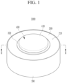
- a rechargeable battery according to an embodiment is an ultra-small rechargeable battery and may be a coin-type battery (e.g., a coin cell) or a button-type battery (e.g., a button cell) but is not limited thereto.
- the rechargeable battery may be a cylindrical or pin-type battery.
- the coin-type battery or the button-type battery is a thin coin or button-type battery and may imply a battery of which a ratio (e.g., a height / diameter ratio) of a height to a diameter is 1 or less, but this is not restrictive. Because the coin-type battery or the button-type battery is generally (or primarily) cylindrical, the cross-section in the horizontal direction is circular, but the present disclosure is not limited thereto. In some embodiments, the rechargeable battery may have an elliptical or polygonal shape in the horizontal direction.
- the diameter may be a maximum distance with reference to the horizontal direction of the battery, and the height may be a maximum distance (e.g., a distance from a flat top surface to a flat bottom surface in a cross-section) with the vertical direction of the battery as a reference.
- FIG. 1 is a perspective view of a rechargeable battery according to an embodiment
- FIG. 2 is a cross-sectional view taken along the line II-II in FIG. 1 .
- a rechargeable battery 1000 includes an electrode assembly 100, a case 200, a cap plate 300, and a terminal portion 400.
- the electrode assembly 100 is accommodated in the case 200.
- a lower portion of the electrode assembly 100 faces a bottom portion of the case 200, and an upper portion of the electrode assembly 100 faces the cap plate 300 and the terminal portion 400 covering, preferably fully covering an opening 210 of the case 200.
- the upper and lower portions of the electrode assembly 100 may have a planar shape parallel to each other, but the present disclosure is not limited thereto.
- the electrode assembly 100 includes a first electrode 110, a second electrode 120, a separator 130, a first electrode tab 140, and a second electrode tab 150.
- the first electrode 110 and the second electrode 120 are spaced apart from each other, and a separator 130 including an insulating material is positioned between the first electrode 110 and the second electrode 120.
- the first electrode 110 may be an anode
- the second electrode 120 may be a cathode, but they are not limited thereto.
- the first electrode 110 may be a cathode
- the second electrode 120 may be an anode.
- the first electrode 110 has a band shape extending in one direction and includes an anode coated region, where an anode active material layer is applied to a current collector of a metal foil (e.g., a Cu foil), and an anode uncoated region, where no active material is applied.
- the anode uncoated region may be positioned at one end in the extension direction of the first electrode 110.
- the second electrode 120 has a band shape extending in one direction while being spaced apart from the first electrode 110 with the separator 130 therebetween and includes a cathode coated region, where a cathode active material layer is applied to a current collector of a metal foil (e.g., an Al foil) and a cathode uncoated region, where no active material is applied.
- a cathode active material layer is applied to a current collector of a metal foil (e.g., an Al foil) and a cathode uncoated region, where no active material is applied.
- the cathode uncoated region may be located at one end in the extending direction of the second electrode 120.
- the separator 130 extends in one direction between the first electrode 110 and the second electrode 120 to prevent a short circuit between the first electrode 110 and the second electrode 120.
- the first electrode 110, the separator 130, and the second electrode 120 are sequentially stacked and wound in the form of a jelly roll.
- the present disclosure is not limited thereto, and the first electrode 110, the separator 130, and the second electrode 120 may be formed in various known shapes.
- Each of the first electrode 110, the second electrode 120, and the separator 130 may include various known materials.
- the first electrode tab 140 extends from the first electrode 110 of the electrode assembly 100 to the case 200.
- the first electrode tab 140 is coupled to the bottom portion of the case 200 to connect the first electrode 110 and the case 200 to each other.
- the first electrode tab 140 contacts the first electrode 110 and the case 200.
- the first electrode tab 140 is welded to the bottom portion of the case 200, but the present disclosure is not limited thereto.
- the case 200 has the same polarity as the first electrode 110 via the first electrode tab 140.
- the second electrode tab 150 extends from the second electrode 120 of the electrode assembly 100 to the terminal portion 400.
- the second electrode tab 150 is coupled to a plating layer 410 of the terminal portion 400 to connect the second electrode 120 and the terminal portion 400 to each other.
- the second electrode tab 150 contacts the second electrode 120 and the terminal portion 400.
- the second electrode tab 150 is coupled, preferably welded to the surface of the plating layer 410 of the terminal portion 400, but the present disclosure is not limited thereto.
- the terminal portion 400 has the same polarity as that of the second electrode 120 via the second electrode tab 150.
- a center pin penetrating (e.g., extending through) the center of the electrode assembly 100 in the vertical direction may be positioned in a central portion of the electrode assembly 100.
- the center pin may support the first electrode tab 140 and the second electrode tab 150, but the present disclosure is not limited thereto.
- the case 200 is connected to the first electrode 110 of the electrode assembly 100 and accommodates the electrode assembly 100.
- the case 200 has an opening 210 exposing the top of the electrode assembly 100. Because the first electrode tab 140 is connected, preferably welded to the bottom portion of the case 200 and connected to the first electrode 110 of the electrode assembly 100, the case 200 has the same polarity as the first electrode 110.
- the case 200 may be a cylinder-shaped can for accommodating the electrode assembly 100 in a jelly roll form, but the case 200 is not limited thereto and may have various known forms and/or shapes.
- the case 200 may accommodate a variety of known electrolyte solutions together with the electrode assembly 100.
- An outer surface of the case 200 may be a first electrode terminal of the rechargeable battery 1000, but the present disclosure is not limited thereto.
- a top surface of the plating layer 410 which is the outer surface of the terminal portion 400, may be a second electrode terminal of the rechargeable battery 1000, but the present disclosure is not limited thereto.
- the case 200 includes stainless steel, but it is not limited thereto and may include another metal, such as aluminum or nickel and copper.
- another plating layer may be coated on the outer surface of the case 200, but the present disclosure is not limited thereto and various known coating layers may be coated on the outer surface of the case 200.
- the opening 210 in the case 200 is covered by the cap plate 300 and the terminal portion 400.
- FIG. 3 is an enlarged view of the portion A of FIG. 2 .
- the cap plate 300 is coupled to the case 200 to cover an outer region of the opening 210.
- the cap plate 300 has an opening (e.g., a penetration hole) 310 exposing a central region of the opening 210 and includes an insulation layer 320 coated on the surface of the cap plate 300 corresponding to (e.g., forming or exposed to) the opening 310.
- the surface of the cap plate 300 in the region of the opening 310 is coated with the insulation layer 320.
- the cap plate 300 is directly coupled to a side wall of the case 200 forming the opening 210 in the case 200 by a welding process and the like to cover the outer region of the opening 210.
- the cap plate 300 has a ring shape formed by the opening 310 in the center of the cap plate 300, but the cap plate 300 is not limited thereto.
- the cap plate 300 is coupled with the case 200 and has the same polarity as the first electrode 110.
- the cap plate 300 includes stainless steel, but it is not limited thereto and may include other metals, such as aluminum or nickel and copper.
- the outer surface of the cap plate 300 may be a first electrode terminal of the rechargeable battery 1000, but it is not limited thereto.
- the insulation layer 320 is coated on a portion of the surface of the cap plate 300 corresponding to the opening 310 and insulates between the cap plate 300 and the terminal portion 400.
- the insulation layer 320 includes a first coating layer 321, a second coating layer 322, and a third coating layer 323.
- the first coating layer 321 is coated, preferably directly coated on a side surface of the cap plate 300 forming the opening 310
- the second coating layer 322 is coated, preferably directly coated on an upper surface of the cap plate 300 around the opening 310
- the third coating layer 323 is coated, preferably directly coated on a lower surface of the cap plate 300 around the opening 310.
- the first coating layer 321, the second coating layer 322, and the third coating layer 323 are integrally formed, and the first coating layer 321, the second coating layer 322, and the third coating layer 323 directly contact the plating layer 410 of the terminal portion 400.
- the first coating layer 321, the second coating layer 322, and the third coating layer 323 may together form a c-shaped insulating layer 320.
- the first coating layer 321 is completely covered by the plating layer 410 of the terminal portion 400 while a part of the second coating layer 322 and a part of the third coating layer 323 may not overlap (e.g., are not covered by) the plating layer 410.
- At least 50%, preferably at least 80% of the area of the second or the third coating layer 322, 323 may overlap with (e.g. may be covered by) the plating layer 410.
- the second coating layer 322 is coated on only a portion of the top surface of the cap plate 300, and the third coating layer 323 is coated on only a portion of the lower surface of the cap plate 300, but the present disclosure is not limited thereto.
- each of the second coating layer 322 and the third coating layer 323 may be coated on the entire upper surface and the lower surface of the cap plate 300, respectively.
- the insulation layer 320 may be formed by depositing an insulative ceramic material resistant to a high temperature environment between the cap plate 300 and the terminal portion 400, but the present disclosure is not limited thereto.
- the insulating layer 320 may include an aluminum oxide, a silicon oxide, a silicon nitride, an iron oxide, glass, or the like, but it is not limited thereto.
- the insulation layer 320 may include a variety of known materials that are resistant to high temperature environments, except for polymer materials.
- the terminal portion 400 is connected to the second electrode 120 and joined in an insulated manner to the cap plate 300.
- the terminal portion 400 covers the opening 310 in the cap plate 300 in its enterity.
- the terminal portion 400 is positioned on the cap plate 300, preferably is positioned to be supported by the cap plate 300.
- the terminal portion 400 fully covers the central region of the opening 210 in the case 200 at where the opening 310 in the cap plate 300 is exposed. Because the terminal portion 400 completely covers the central region of the opening 210 and the cap plate 300 covers the outer region of the opening 210 in its entirety, the opening 210 in the case 200 is completely covered by the terminal portion 400 and the cap plate 300.
- the terminal portion 400 tightly seals the electrode assembly 100 together with the case 200 and the cap plate 300.
- the terminal portion 400 is coupled to the second electrode tab 150 of the electrode assembly 100 to be connected to the second electrode 120 of the electrode assembly 100.
- the terminal portion 400 has the same polarity as the second electrode 120.
- the terminal portion 400 includes the plating layer 410 and a first terminal plate 420.
- the plating layer 410 is coated on a surface of the first terminal plate 420 and directly bonded to the insulation layer 320 of the cap plate 300.
- the plating layer 410 closes and seals between the first terminal plate 420 and the insulation layer 320 of the cap plate 300 to close and seal between the cap plate 300 and the terminal portion 400.
- the plating layer 410 may be coated on the surface of the first terminal plate 420 by using various known electroplating or electroless plating processes and may be directly bonded to the insulation layer 320 of the cap plate 300. But the present disclosure is not limited thereto.
- the plating layer 410 directly contacts the first coating layer 321, the second coating layer 322, and the third coating layer 323 of the insulating layer 320.
- the plating layer 410 completely covers the first coating layer 321 and overlaps a part of (e.g., partially covers) the second coating layer 322 and a part of the third coating layer 323.
- the plating layer 410 may include various known conductive materials, such as metal, but it is not limited thereto.
- the first terminal plate 420 includes a flange portion 421 and a protruding portion 422.
- the flange portion 421 is positioned on the cap plate 300 and overlaps the cap plate 300 to completely cover the opening 310.
- the flange portion 421 has a wider area than the protruding portion 422.
- the flange portion 421 may have a larger diameter than the protruding portion 422.
- the flange portion 421 has a smaller thickness than the protruding portion 422, but it is not limited thereto.
- a lower surface of the flange portion 421 contacts, preferably directly contacts the plating layer 410, and the flange portion 421 is bonded to the insulation layer 320 of the cap plate 300 by the plating layer 410.
- the plating layer 410 positioned on an upper surface of the flange portion 421 may be a second electrode terminal of the rechargeable battery 1000.
- the protruding portion 422 protrudes from the flange portion 421 and penetrates (e.g., extends into or through) the opening 310.
- the protruding portion 422 passes through the opening 310 from the flange portion 421 and is connected to the second electrode 120 through the plating layer 410 coated on the protruding portion 422.
- the plating layer 410 positioned on a lower surface of the protruding portion 422 is coupled to or combined with the second electrode tab 150.
- the plating layer 410 positioned on the lower surface of the protruding portion 422 may be welded to the second electrode tab 150, but the present disclosure is not limited thereto.
- the protruding portion 422 is coupled to the second electrode tab 150 through the plating layer 410, the first terminal plate 420 and the plating layer 410 including the protruding portion 422 and the flange portion 421 of the terminal portion 400 have the same polarity as the second electrode 120.
- the lower surface of the protruding portion 422 connected to the second electrode tab 150 may have a smaller diameter than an upper surface of the flange portion 421.
- the terminal portion 400 may have a T-shape.
- the protruding portion 420 of the terminal portion 400 may have a T-shape and the plating layer 410 formed around the protruding portion 420 may have a T-shape.
- the protruding portion 422 and the flange portion 421 are integrally formed, but the present disclosure is not limited thereto and different materials may be combined to form the first terminal plate 420.
- the first terminal plate 420 includes stainless steel, but it is not limited thereto and may include other metals, such as aluminum or nickel and copper.
- the cap plate 300 is directly coupled to the case 200, and the insulating bonding between the cap plate 300 and the terminal portion 400 is carried out by the plating layer 410 of the terminal portion 400, that is directly bonded to the insulation layer 320 (preferably including a ceramic material) coated on the surface of the cap plate 300 corresponding to the opening 310 of the cap plate 300, and thus, sealing by the terminal portion 400, the cap plate 300, and the case 200 is easily performed even in a high temperature and high humidity environment.
- the insulation layer 320 preferably including a ceramic material
- a rechargeable battery 1000 that is strong (e.g., durable or resilient) in a high temperature and high humidity environment is provided.
- FIG. 4 and FIG. 5 a rechargeable battery according to another embodiment will be described.
- parts that are different from the rechargeable battery according to the above-described embodiment will be described.
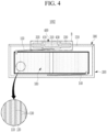
- FIG. 4 is a cross-sectional view of a rechargeable battery according to another embodiment
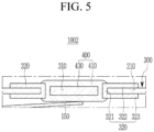
- FIG. 5 is an enlarged view of the part B of FIG. 4 .
- a rechargeable battery 1002 includes an electrode assembly 100, a case 200, a cap plate 300, and a terminal portion 400.
- the terminal portion 400 is connected to the second electrode 120 and bonded in an insulated manner to the cap plate 300.
- the terminal portion 400 completely covers an opening (e.g., a penetration hole) 310 in the cap plate 300.
- the terminal portion 400 is positioned inside the opening 310 in the cap plate 300.
- the terminal portion 400 completely covers a central region of an opening 210 in the case 200 at where the opening 310 in the cap plate 300 is exposed. Because the terminal portion 400 completely covers the central region of the opening 210 and the cap plate 300 covers an outer region of the opening 210 in its entirety, the opening 210 in the case 200 is completely covered by the terminal portion 400 and the cap plate 300.
- the terminal portion 400 tightly seals the electrode assembly 100 together with the case 200 and the cap plate 300.
- the terminal portion 400 is coupled to the second electrode tab 150 of the electrode assembly 100 to be connected to the second electrode 120 of the electrode assembly 100.
- the terminal portion 400 has the same polarity as the second electrode 120.
- the terminal portion 400 includes a plating layer 410 and a second terminal plate 430.
- the plating layer 410 is coated, preferably fully coated on a surface of the second terminal plate 430 and directly bonded to an insulation layer 320 of the cap plate 300.
- the plating layer 410 closes and seals between the second terminal plate 430 and the insulation layer 320 of the cap plate 300 to close and seal between the cap plate 300 and the terminal portion 400.
- the plating layer 410 may be coated on a surface of the second terminal plate 430 by using various known electroplating or electroless plating processes and may be directly bonded to the insulation layer 320 of the cap plate 300. But the present disclosure is not limited thereto.
- the plating layer 410 directly contacts the first coating layer 321, the second coating layer 322, and the third coating layer 323 of the insulation layer 320.
- the plating layer 410 completely covers the first coating layer 321, and overlaps a part of (e.g., partially covers) the second coating layer 322 and a part of the third coating layer 323.
- the plating layer 410 may include various known conductive materials, such as a metal, but it is not limited thereto.
- the second terminal plate 430 is positioned inside the opening 310 in the cap plate 300 to cover at least a part of the opening 310 in the cap plate 300.
- the second terminal plate 430 has a smaller diameter than a diameter of the opening 310.
- the second terminal plate 430 is bonded to the insulation layer 320 of the cap plate 300 by the plating layer 410.
- the plating layer 410 positioned on a lower surface of the second terminal plate 430 is coupled with the second electrode tab 150, and the plating layer 410 positioned on an upper surface of the second terminal plate 430 may be a second electrode terminal of the rechargeable battery 1002.
- the plating layer 410 positioned on a lower surface of the second terminal plate 430 may be welded to the second electrode tab 150, but it is not limited thereto.
- the second terminal plate 430 is coupled with the second electrode tab 150 through the plating layer 410, the second terminal plate 430 and the plating layer 410 of the terminal portion 400 have the same polarity as the second electrode 120.
- the second terminal plate 430 includes stainless steel, but this is not restrictive, and the second terminal plate 430 may include other metals, such as aluminum or nickel and copper.
- the terminal portion 400 may have a disc shape with a circumferential indentation connectable to the insulation layer 320 at the periphery of the opening 310.
- the cap plate 300 is directly coupled to the case 200, and the insulating bonding between the cap plate 300 and the terminal portion 400 is carried out by the plating layer 410 of the terminal portion 400 that is directly bonded to the insulation layer 320 (preferably including a ceramic material) coated on the surface of the cap plate 300 corresponding to the opening 310 in the cap plate 300, and thus, sealing by the terminal portion 400, the cap plate 300, and the case 200 is easily performed even in a high temperature and high humidity environment.
- the insulation layer 320 preferably including a ceramic material
- a rechargeable battery 1002 that is strong (e.g., durable or resilient) in a high temperature and high humidity environment is provided.
- FIG. 6 and FIG. 7 a rechargeable battery according to another embodiment will be described.
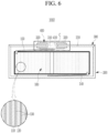
- FIG. 6 is a cross-sectional view of a rechargeable battery according to another embodiment
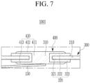
- FIG. 7 is an enlarged view of the part C of FIG. 6 .
- a rechargeable battery 1003 includes an electrode assembly 100, a case 200, a cap plate 300, and a terminal portion 400.
- the terminal portion 400 is connected to the second electrode 120 and is bonded in an insulated manner to the cap plate 300.
- the terminal portion 400 completely covers an opening (e.g., a penetration hole) 310 in the cap plate 300.
- the terminal portion 400 fills the opening 310 in the cap plate 300.
- the terminal portion 400 completely covers a central region of an opening 210 in the case 200 to which the opening 310 in the cap plate 300 is exposed. Because the terminal portion 400 completely covers the central region of the opening 210 and the cap plate 300 covers an outer region of the opening 210 in its entirety, the opening 210 in the case 200 is completely covered by the terminal portion 400 and the cap plate 300.
- the terminal portion 400 tightly seals the electrode assembly 100 together with the case 200 and the cap plate 300.
- the terminal portion 400 is coupled to the second electrode tab 150 of the electrode assembly 100 to be connected to the second electrode 120 of the electrode assembly 100.
- the terminal portion 400 has the same polarity as the second electrode 120.
- the terminal portion 400 includes a plating layer 410.
- the plating layer 410 completely fills the opening 310 in the cap plate 300 and is directly bonded to an insulation layer 320 of the cap plate 300.
- the plating layer 410 closes and seals the opening 310 between the insulation layer 320 of the cap plate 300 to close and seal the cap plate 300 and the terminal portion 400.
- the opening 310 in the cap plate 300 filled with the plating layer 410 may have a smaller diameter than the opening 310 in the rechargeable battery 1000 according to an above-mentioned embodiment or the opening 310 in the rechargeable battery 1002 according to the other embodiment, but it is not limited thereto.
- the plating layer 410 may be directly bonded to the insulation layer 320 of the cap plate 300 by completely filling the opening 310 in the cap plate 300 by using various known electroplating or electroless plating processes, but it is not limited thereto.
- the plating layer 410 directly contacts the first coating layer 321, the second coating layer 322, and the third coating layer 323 of the insulation layer 320.
- the plating layer 410 completely covers the first coating layer 321, and overlaps a part of (e.g., partially covers) the second coating layer 322 and a part of the third coating layer 323.
- the plating layer 410 includes a first plating portion 411, a second plating portion 412, and a third plating portion 413.
- the first plating portion 411 fills the opening 310 and directly contacts the first coating layer 321
- the second plating portion 412 directly contacts the second coating layer 322 by covering an upper surface of the cap plate 300 from the first plating portion 411
- the third plating portion 413 directly contacts the third coating layer 323 by covering a lower surface of the cap plate 300 from the first plating portion 411.
- the first plating portion 411, the second plating portion 412, and the third plating portion 413 are integrally formed, but plating layer 410 is not limited thereto. At least one of the first plating portion 411, the second plating portion 412, and the third plating portion 413 may contain a different conductive material than the other portion(s).
- At least one of the first plating portion 411, the second plating portion 412, and the third plating portion 413 may be formed as a plating seed layer and the other portion(s) may be formed as a plating growth layer, but the present disclosure is not limited thereto.
- the terminal portion 400 is positioned inside the opening 310 in the cap plate 300 by the plating layer 410.
- the third plating portion 413 of the plating layer 410 is coupled with the second electrode tab 150, and the second plating portion 412 may be a second electrode terminal of the rechargeable battery 1003.
- the third plating portion 413 of the plating layer 410 may be welded to the second electrode tab 150, but it is not limited thereto. Because the plating layer 410 is coupled with the second electrode tab 150, the terminal portion 400 has the same polarity as that of the second electrode 120.
- the plating layer 410 may include various known conductive materials, such as a metal, but it is not limited thereto.
- the cap plate 300 is directly coupled to the case 200, and the insulating bonding between the cap plate 300 and the terminal portion 400 is carried out by the plating layer 410 of the terminal portion 400 that is directly bonded to the insulation layer 320 (preferably including a ceramic material) coated on the surface of the cap plate 300 corresponding to the opening 310 in the cap plate 300, and thus, sealing by the terminal portion 400, the cap plate 300, and the case 200 is easily performed even in a high temperature and high humidity environment.
- the insulation layer 320 preferably including a ceramic material
- a rechargeable battery 1003 that is strong (e.g., durable or resilient) in a high temperature and high humidity environment is provided.
Landscapes
- Chemical & Material Sciences (AREA)
- Chemical Kinetics & Catalysis (AREA)
- Electrochemistry (AREA)
- General Chemical & Material Sciences (AREA)
- Engineering & Computer Science (AREA)
- Manufacturing & Machinery (AREA)
- Inorganic Chemistry (AREA)
- Sealing Battery Cases Or Jackets (AREA)
- Telephone Function (AREA)
- Connection Of Batteries Or Terminals (AREA)
Applications Claiming Priority (1)
| Application Number | Priority Date | Filing Date | Title |
|---|---|---|---|
| KR1020210007544A KR20220105018A (ko) | 2021-01-19 | 2021-01-19 | 이차 전지 |
Publications (2)
| Publication Number | Publication Date |
|---|---|
| EP4030539A1 EP4030539A1 (en) | 2022-07-20 |
| EP4030539B1 true EP4030539B1 (en) | 2024-10-23 |
Family
ID=79601763
Family Applications (1)
| Application Number | Title | Priority Date | Filing Date |
|---|---|---|---|
| EP22151348.4A Active EP4030539B1 (en) | 2021-01-19 | 2022-01-13 | Rechargeable battery |
Country Status (6)
| Country | Link |
|---|---|
| US (1) | US20220231362A1 (ko) |
| EP (1) | EP4030539B1 (ko) |
| KR (1) | KR20220105018A (ko) |
| CN (1) | CN114824411A (ko) |
| HU (1) | HUE069565T2 (ko) |
| PL (1) | PL4030539T3 (ko) |
Families Citing this family (1)
| Publication number | Priority date | Publication date | Assignee | Title |
|---|---|---|---|---|
| WO2026065472A1 (zh) * | 2024-09-30 | 2026-04-02 | 宁德时代新能源科技股份有限公司 | 电池单体、电池装置以及用电设备 |
Citations (1)
| Publication number | Priority date | Publication date | Assignee | Title |
|---|---|---|---|---|
| US20210328290A1 (en) * | 2018-08-16 | 2021-10-21 | Lg Chem, Ltd. | Secondary Battery |
Family Cites Families (18)
| Publication number | Priority date | Publication date | Assignee | Title |
|---|---|---|---|---|
| KR100349911B1 (ko) * | 1999-12-27 | 2002-08-22 | 삼성에스디아이 주식회사 | 각형 밀폐전지 및 그 제조방법 |
| US6830847B2 (en) * | 2001-04-10 | 2004-12-14 | The Gillette Company | Zinc/air cell |
| JP2004071265A (ja) * | 2002-08-05 | 2004-03-04 | Sanyo Electric Co Ltd | 電池 |
| JP4135516B2 (ja) * | 2003-01-23 | 2008-08-20 | ソニー株式会社 | リード端子及び電源装置 |
| JP4507159B2 (ja) * | 2003-08-01 | 2010-07-21 | 日立マクセル株式会社 | 密閉型電池 |
| US7341802B1 (en) * | 2004-03-25 | 2008-03-11 | Quallion Llc | Feedthrough assembly and method |
| US7892674B2 (en) * | 2005-09-09 | 2011-02-22 | Kabushiki Kaisha Toshiba | Nonaqueous electrolyte secondary battery and battery module |
| WO2009069944A2 (en) * | 2007-11-29 | 2009-06-04 | Lg Chem, Ltd. | Secondary battery pack of compact structure |
| US7563118B1 (en) * | 2008-06-20 | 2009-07-21 | Delphi Technologies, Inc. | High temperature connector |
| JP5753317B2 (ja) * | 2011-06-28 | 2015-07-22 | シェンゼェン ビーワイディー オート アールアンドディー カンパニーリミテッド | カバーアセンブリおよびそれを備えるバッテリ |
| WO2015125487A1 (ja) * | 2014-02-21 | 2015-08-27 | 株式会社リチウムエナジージャパン | 蓄電素子及び蓄電素子の製造方法 |
| US10193126B2 (en) * | 2014-10-24 | 2019-01-29 | Hitachi Metals, Ltd. | Battery terminal, method for manufacturing battery terminal, and battery |
| US10199630B2 (en) * | 2015-08-21 | 2019-02-05 | TOP Battery Co., Ltd | Electrode terminal, electro-chemical device and electro-chemical device comprising same |
| KR102515095B1 (ko) * | 2015-11-25 | 2023-03-27 | 삼성에스디아이 주식회사 | 이차 전지 |
| CN107359290A (zh) * | 2017-07-10 | 2017-11-17 | 林州朗坤科技有限公司 | 一种锂电池盖板组件及其制造方法 |
| JP7171183B2 (ja) * | 2017-12-19 | 2022-11-15 | 三洋電機株式会社 | 二次電池及びそれを用いた組電池 |
| CN210379128U (zh) * | 2020-02-27 | 2020-04-21 | 比亚迪股份有限公司 | 纽扣电池 |
| KR20220000672A (ko) * | 2020-06-26 | 2022-01-04 | 삼성에스디아이 주식회사 | 이차 전지 |
-
2021
- 2021-01-19 KR KR1020210007544A patent/KR20220105018A/ko active Pending
- 2021-12-27 US US17/646,037 patent/US20220231362A1/en active Pending
-
2022
- 2022-01-07 CN CN202210015719.7A patent/CN114824411A/zh active Pending
- 2022-01-13 HU HUE22151348A patent/HUE069565T2/hu unknown
- 2022-01-13 PL PL22151348.4T patent/PL4030539T3/pl unknown
- 2022-01-13 EP EP22151348.4A patent/EP4030539B1/en active Active
Patent Citations (1)
| Publication number | Priority date | Publication date | Assignee | Title |
|---|---|---|---|---|
| US20210328290A1 (en) * | 2018-08-16 | 2021-10-21 | Lg Chem, Ltd. | Secondary Battery |
Also Published As
| Publication number | Publication date |
|---|---|
| EP4030539A1 (en) | 2022-07-20 |
| CN114824411A (zh) | 2022-07-29 |
| PL4030539T3 (pl) | 2025-02-17 |
| HUE069565T2 (hu) | 2025-03-28 |
| US20220231362A1 (en) | 2022-07-21 |
| KR20220105018A (ko) | 2022-07-26 |
Similar Documents
| Publication | Publication Date | Title |
|---|---|---|
| US11545709B2 (en) | Rechargeable battery | |
| EP3930087B1 (en) | Rechargeable battery | |
| US20240170710A1 (en) | Button cell | |
| EP3930092B1 (en) | Rechargeable battery | |
| EP4340099A1 (en) | Cylindrical secondary battery | |
| EP4350854A2 (en) | Button cell | |
| US20240170775A1 (en) | Button cell | |
| EP4498484A2 (en) | Button cell | |
| CN116470199A (zh) | 圆柱形二次电池 | |
| EP4030539B1 (en) | Rechargeable battery | |
| EP3930085B1 (en) | Rechargeable battery | |
| EP4175032A9 (en) | Rechargeable battery | |
| US20220336897A1 (en) | Rechargeable battery | |
| US20230170560A1 (en) | Rechargeable battery | |
| KR102927442B1 (ko) | 이차 전지 | |
| US20220359935A1 (en) | Rechargeable battery | |
| US20260112681A1 (en) | Secondary battery and method for manufacturing the same | |
| US20260074382A1 (en) | Rechargeable battery | |
| KR20260059306A (ko) | 이차 전지 및 이차 전지의 제조 방법 |
Legal Events
| Date | Code | Title | Description |
|---|---|---|---|
| PUAI | Public reference made under article 153(3) epc to a published international application that has entered the european phase |
Free format text: ORIGINAL CODE: 0009012 |
|
| STAA | Information on the status of an ep patent application or granted ep patent |
Free format text: STATUS: REQUEST FOR EXAMINATION WAS MADE |
|
| 17P | Request for examination filed |
Effective date: 20220113 |
|
| AK | Designated contracting states |
Kind code of ref document: A1 Designated state(s): AL AT BE BG CH CY CZ DE DK EE ES FI FR GB GR HR HU IE IS IT LI LT LU LV MC MK MT NL NO PL PT RO RS SE SI SK SM TR |
|
| GRAP | Despatch of communication of intention to grant a patent |
Free format text: ORIGINAL CODE: EPIDOSNIGR1 |
|
| STAA | Information on the status of an ep patent application or granted ep patent |
Free format text: STATUS: GRANT OF PATENT IS INTENDED |
|
| RIC1 | Information provided on ipc code assigned before grant |
Ipc: H01M 50/188 20210101ALI20240626BHEP Ipc: H01M 50/562 20210101ALI20240626BHEP Ipc: H01M 50/559 20210101ALI20240626BHEP Ipc: H01M 50/545 20210101ALI20240626BHEP Ipc: H01M 50/191 20210101ALI20240626BHEP Ipc: H01M 50/181 20210101ALI20240626BHEP Ipc: H01M 50/164 20210101ALI20240626BHEP Ipc: H01M 50/148 20210101ALI20240626BHEP Ipc: H01M 50/153 20210101AFI20240626BHEP |
|
| INTG | Intention to grant announced |
Effective date: 20240712 |
|
| GRAS | Grant fee paid |
Free format text: ORIGINAL CODE: EPIDOSNIGR3 |
|
| GRAA | (expected) grant |
Free format text: ORIGINAL CODE: 0009210 |
|
| STAA | Information on the status of an ep patent application or granted ep patent |
Free format text: STATUS: THE PATENT HAS BEEN GRANTED |
|
| AK | Designated contracting states |
Kind code of ref document: B1 Designated state(s): AL AT BE BG CH CY CZ DE DK EE ES FI FR GB GR HR HU IE IS IT LI LT LU LV MC MK MT NL NO PL PT RO RS SE SI SK SM TR |
|
| REG | Reference to a national code |
Ref country code: GB Ref legal event code: FG4D |
|
| REG | Reference to a national code |
Ref country code: CH Ref legal event code: EP |
|
| REG | Reference to a national code |
Ref country code: DE Ref legal event code: R096 Ref document number: 602022006927 Country of ref document: DE |
|
| REG | Reference to a national code |
Ref country code: IE Ref legal event code: FG4D |
|
| REG | Reference to a national code |
Ref country code: SE Ref legal event code: TRGR |
|
| REG | Reference to a national code |
Ref country code: LT Ref legal event code: MG9D |
|
| REG | Reference to a national code |
Ref country code: NL Ref legal event code: MP Effective date: 20241023 |
|
| REG | Reference to a national code |
Ref country code: AT Ref legal event code: MK05 Ref document number: 1735599 Country of ref document: AT Kind code of ref document: T Effective date: 20241023 |
|
| PG25 | Lapsed in a contracting state [announced via postgrant information from national office to epo] |
Ref country code: NL Free format text: LAPSE BECAUSE OF FAILURE TO SUBMIT A TRANSLATION OF THE DESCRIPTION OR TO PAY THE FEE WITHIN THE PRESCRIBED TIME-LIMIT Effective date: 20241023 |
|
| REG | Reference to a national code |
Ref country code: HU Ref legal event code: AG4A Ref document number: E069565 Country of ref document: HU |
|
| PG25 | Lapsed in a contracting state [announced via postgrant information from national office to epo] |
Ref country code: NL Free format text: LAPSE BECAUSE OF FAILURE TO SUBMIT A TRANSLATION OF THE DESCRIPTION OR TO PAY THE FEE WITHIN THE PRESCRIBED TIME-LIMIT Effective date: 20241023 |
|
| PG25 | Lapsed in a contracting state [announced via postgrant information from national office to epo] |
Ref country code: HR Free format text: LAPSE BECAUSE OF FAILURE TO SUBMIT A TRANSLATION OF THE DESCRIPTION OR TO PAY THE FEE WITHIN THE PRESCRIBED TIME-LIMIT Effective date: 20241023 Ref country code: PT Free format text: LAPSE BECAUSE OF FAILURE TO SUBMIT A TRANSLATION OF THE DESCRIPTION OR TO PAY THE FEE WITHIN THE PRESCRIBED TIME-LIMIT Effective date: 20250224 Ref country code: IS Free format text: LAPSE BECAUSE OF FAILURE TO SUBMIT A TRANSLATION OF THE DESCRIPTION OR TO PAY THE FEE WITHIN THE PRESCRIBED TIME-LIMIT Effective date: 20250223 |
|
| PG25 | Lapsed in a contracting state [announced via postgrant information from national office to epo] |
Ref country code: FI Free format text: LAPSE BECAUSE OF FAILURE TO SUBMIT A TRANSLATION OF THE DESCRIPTION OR TO PAY THE FEE WITHIN THE PRESCRIBED TIME-LIMIT Effective date: 20241023 |
|
| PG25 | Lapsed in a contracting state [announced via postgrant information from national office to epo] |
Ref country code: BG Free format text: LAPSE BECAUSE OF FAILURE TO SUBMIT A TRANSLATION OF THE DESCRIPTION OR TO PAY THE FEE WITHIN THE PRESCRIBED TIME-LIMIT Effective date: 20241023 |
|
| PG25 | Lapsed in a contracting state [announced via postgrant information from national office to epo] |
Ref country code: ES Free format text: LAPSE BECAUSE OF FAILURE TO SUBMIT A TRANSLATION OF THE DESCRIPTION OR TO PAY THE FEE WITHIN THE PRESCRIBED TIME-LIMIT Effective date: 20241023 |
|
| PG25 | Lapsed in a contracting state [announced via postgrant information from national office to epo] |
Ref country code: NO Free format text: LAPSE BECAUSE OF FAILURE TO SUBMIT A TRANSLATION OF THE DESCRIPTION OR TO PAY THE FEE WITHIN THE PRESCRIBED TIME-LIMIT Effective date: 20250123 |
|
| PG25 | Lapsed in a contracting state [announced via postgrant information from national office to epo] |
Ref country code: LV Free format text: LAPSE BECAUSE OF FAILURE TO SUBMIT A TRANSLATION OF THE DESCRIPTION OR TO PAY THE FEE WITHIN THE PRESCRIBED TIME-LIMIT Effective date: 20241023 Ref country code: GR Free format text: LAPSE BECAUSE OF FAILURE TO SUBMIT A TRANSLATION OF THE DESCRIPTION OR TO PAY THE FEE WITHIN THE PRESCRIBED TIME-LIMIT Effective date: 20250124 Ref country code: AT Free format text: LAPSE BECAUSE OF FAILURE TO SUBMIT A TRANSLATION OF THE DESCRIPTION OR TO PAY THE FEE WITHIN THE PRESCRIBED TIME-LIMIT Effective date: 20241023 |
|
| PG25 | Lapsed in a contracting state [announced via postgrant information from national office to epo] |
Ref country code: RS Free format text: LAPSE BECAUSE OF FAILURE TO SUBMIT A TRANSLATION OF THE DESCRIPTION OR TO PAY THE FEE WITHIN THE PRESCRIBED TIME-LIMIT Effective date: 20250123 |
|
| PG25 | Lapsed in a contracting state [announced via postgrant information from national office to epo] |
Ref country code: SM Free format text: LAPSE BECAUSE OF FAILURE TO SUBMIT A TRANSLATION OF THE DESCRIPTION OR TO PAY THE FEE WITHIN THE PRESCRIBED TIME-LIMIT Effective date: 20241023 |
|
| PG25 | Lapsed in a contracting state [announced via postgrant information from national office to epo] |
Ref country code: DK Free format text: LAPSE BECAUSE OF FAILURE TO SUBMIT A TRANSLATION OF THE DESCRIPTION OR TO PAY THE FEE WITHIN THE PRESCRIBED TIME-LIMIT Effective date: 20241023 |
|
| PG25 | Lapsed in a contracting state [announced via postgrant information from national office to epo] |
Ref country code: EE Free format text: LAPSE BECAUSE OF FAILURE TO SUBMIT A TRANSLATION OF THE DESCRIPTION OR TO PAY THE FEE WITHIN THE PRESCRIBED TIME-LIMIT Effective date: 20241023 |
|
| PG25 | Lapsed in a contracting state [announced via postgrant information from national office to epo] |
Ref country code: RO Free format text: LAPSE BECAUSE OF FAILURE TO SUBMIT A TRANSLATION OF THE DESCRIPTION OR TO PAY THE FEE WITHIN THE PRESCRIBED TIME-LIMIT Effective date: 20241023 |
|
| REG | Reference to a national code |
Ref country code: DE Ref legal event code: R097 Ref document number: 602022006927 Country of ref document: DE |
|
| PG25 | Lapsed in a contracting state [announced via postgrant information from national office to epo] |
Ref country code: SK Free format text: LAPSE BECAUSE OF FAILURE TO SUBMIT A TRANSLATION OF THE DESCRIPTION OR TO PAY THE FEE WITHIN THE PRESCRIBED TIME-LIMIT Effective date: 20241023 |
|
| PG25 | Lapsed in a contracting state [announced via postgrant information from national office to epo] |
Ref country code: CZ Free format text: LAPSE BECAUSE OF FAILURE TO SUBMIT A TRANSLATION OF THE DESCRIPTION OR TO PAY THE FEE WITHIN THE PRESCRIBED TIME-LIMIT Effective date: 20241023 |
|
| PG25 | Lapsed in a contracting state [announced via postgrant information from national office to epo] |
Ref country code: IT Free format text: LAPSE BECAUSE OF FAILURE TO SUBMIT A TRANSLATION OF THE DESCRIPTION OR TO PAY THE FEE WITHIN THE PRESCRIBED TIME-LIMIT Effective date: 20241023 |
|
| PLBE | No opposition filed within time limit |
Free format text: ORIGINAL CODE: 0009261 |
|
| REG | Reference to a national code |
Ref country code: CH Ref legal event code: PL |
|
| STAA | Information on the status of an ep patent application or granted ep patent |
Free format text: STATUS: NO OPPOSITION FILED WITHIN TIME LIMIT |
|
| PG25 | Lapsed in a contracting state [announced via postgrant information from national office to epo] |
Ref country code: LU Free format text: LAPSE BECAUSE OF NON-PAYMENT OF DUE FEES Effective date: 20250113 Ref country code: MC Free format text: LAPSE BECAUSE OF FAILURE TO SUBMIT A TRANSLATION OF THE DESCRIPTION OR TO PAY THE FEE WITHIN THE PRESCRIBED TIME-LIMIT Effective date: 20241023 |
|
| 26N | No opposition filed |
Effective date: 20250724 |
|
| PG25 | Lapsed in a contracting state [announced via postgrant information from national office to epo] |
Ref country code: BE Free format text: LAPSE BECAUSE OF NON-PAYMENT OF DUE FEES Effective date: 20250131 |
|
| PG25 | Lapsed in a contracting state [announced via postgrant information from national office to epo] |
Ref country code: CH Free format text: LAPSE BECAUSE OF NON-PAYMENT OF DUE FEES Effective date: 20250131 |
|
| REG | Reference to a national code |
Ref country code: BE Ref legal event code: MM Effective date: 20250131 |
|
| PGFP | Annual fee paid to national office [announced via postgrant information from national office to epo] |
Ref country code: FR Payment date: 20251231 Year of fee payment: 5 |
|
| PG25 | Lapsed in a contracting state [announced via postgrant information from national office to epo] |
Ref country code: IE Free format text: LAPSE BECAUSE OF NON-PAYMENT OF DUE FEES Effective date: 20250113 |
|
| PGFP | Annual fee paid to national office [announced via postgrant information from national office to epo] |
Ref country code: PL Payment date: 20251230 Year of fee payment: 5 |
|
| PGFP | Annual fee paid to national office [announced via postgrant information from national office to epo] |
Ref country code: HU Payment date: 20260130 Year of fee payment: 5 |
|
| PGFP | Annual fee paid to national office [announced via postgrant information from national office to epo] |
Ref country code: SE Payment date: 20251230 Year of fee payment: 5 |
|
| PGFP | Annual fee paid to national office [announced via postgrant information from national office to epo] |
Ref country code: GB Payment date: 20260106 Year of fee payment: 5 |
|
| PGFP | Annual fee paid to national office [announced via postgrant information from national office to epo] |
Ref country code: DE Payment date: 20251230 Year of fee payment: 5 |