EP4030242A1 - Verfahren zur herstellung von uhrwerks-spiralfedern - Google Patents
Verfahren zur herstellung von uhrwerks-spiralfedern Download PDFInfo
- Publication number
- EP4030242A1 EP4030242A1 EP22151557.0A EP22151557A EP4030242A1 EP 4030242 A1 EP4030242 A1 EP 4030242A1 EP 22151557 A EP22151557 A EP 22151557A EP 4030242 A1 EP4030242 A1 EP 4030242A1
- Authority
- EP
- European Patent Office
- Prior art keywords
- stiffness
- dimension
- hairspring
- hairsprings
- carried out
- Prior art date
- Legal status (The legal status is an assumption and is not a legal conclusion. Google has not performed a legal analysis and makes no representation as to the accuracy of the status listed.)
- Pending
Links
- 238000000034 method Methods 0.000 title claims abstract description 27
- 238000004519 manufacturing process Methods 0.000 title claims abstract description 23
- 239000000463 material Substances 0.000 claims abstract description 56
- VYPSYNLAJGMNEJ-UHFFFAOYSA-N Silicium dioxide Chemical compound O=[Si]=O VYPSYNLAJGMNEJ-UHFFFAOYSA-N 0.000 claims description 22
- XUIMIQQOPSSXEZ-UHFFFAOYSA-N Silicon Chemical compound [Si] XUIMIQQOPSSXEZ-UHFFFAOYSA-N 0.000 claims description 19
- 238000011156 evaluation Methods 0.000 claims description 19
- 229910052710 silicon Inorganic materials 0.000 claims description 14
- 239000010703 silicon Substances 0.000 claims description 14
- 238000005259 measurement Methods 0.000 claims description 10
- 235000012239 silicon dioxide Nutrition 0.000 claims description 8
- 239000000377 silicon dioxide Substances 0.000 claims description 8
- 238000005070 sampling Methods 0.000 claims description 5
- 230000001590 oxidative effect Effects 0.000 claims description 3
- 235000012431 wafers Nutrition 0.000 description 31
- 238000012937 correction Methods 0.000 description 21
- 239000010410 layer Substances 0.000 description 21
- 239000006185 dispersion Substances 0.000 description 13
- 238000013459 approach Methods 0.000 description 11
- 238000007254 oxidation reaction Methods 0.000 description 8
- 238000005530 etching Methods 0.000 description 6
- 230000003647 oxidation Effects 0.000 description 6
- 229910021421 monocrystalline silicon Inorganic materials 0.000 description 5
- 238000003754 machining Methods 0.000 description 4
- 239000000758 substrate Substances 0.000 description 4
- KRHYYFGTRYWZRS-UHFFFAOYSA-N Fluorane Chemical compound F KRHYYFGTRYWZRS-UHFFFAOYSA-N 0.000 description 3
- 239000013626 chemical specie Substances 0.000 description 3
- 238000000708 deep reactive-ion etching Methods 0.000 description 3
- 238000009826 distribution Methods 0.000 description 3
- 238000001459 lithography Methods 0.000 description 3
- 229910052814 silicon oxide Inorganic materials 0.000 description 3
- 229910021417 amorphous silicon Inorganic materials 0.000 description 2
- QVGXLLKOCUKJST-UHFFFAOYSA-N atomic oxygen Chemical compound [O] QVGXLLKOCUKJST-UHFFFAOYSA-N 0.000 description 2
- 239000003607 modifier Substances 0.000 description 2
- 230000010355 oscillation Effects 0.000 description 2
- 229910052760 oxygen Inorganic materials 0.000 description 2
- 239000001301 oxygen Substances 0.000 description 2
- 238000000206 photolithography Methods 0.000 description 2
- 238000012545 processing Methods 0.000 description 2
- 239000011241 protective layer Substances 0.000 description 2
- 230000001105 regulatory effect Effects 0.000 description 2
- 238000010200 validation analysis Methods 0.000 description 2
- ZOXJGFHDIHLPTG-UHFFFAOYSA-N Boron Chemical compound [B] ZOXJGFHDIHLPTG-UHFFFAOYSA-N 0.000 description 1
- OKTJSMMVPCPJKN-UHFFFAOYSA-N Carbon Chemical compound [C] OKTJSMMVPCPJKN-UHFFFAOYSA-N 0.000 description 1
- OAICVXFJPJFONN-UHFFFAOYSA-N Phosphorus Chemical compound [P] OAICVXFJPJFONN-UHFFFAOYSA-N 0.000 description 1
- 229910004298 SiO 2 Inorganic materials 0.000 description 1
- 229910052787 antimony Inorganic materials 0.000 description 1
- WATWJIUSRGPENY-UHFFFAOYSA-N antimony atom Chemical compound [Sb] WATWJIUSRGPENY-UHFFFAOYSA-N 0.000 description 1
- 229910052785 arsenic Inorganic materials 0.000 description 1
- RQNWIZPPADIBDY-UHFFFAOYSA-N arsenic atom Chemical compound [As] RQNWIZPPADIBDY-UHFFFAOYSA-N 0.000 description 1
- 230000015572 biosynthetic process Effects 0.000 description 1
- 229910052796 boron Inorganic materials 0.000 description 1
- 238000004364 calculation method Methods 0.000 description 1
- 229910052799 carbon Inorganic materials 0.000 description 1
- 239000000919 ceramic Substances 0.000 description 1
- 239000002131 composite material Substances 0.000 description 1
- 238000010276 construction Methods 0.000 description 1
- 230000008602 contraction Effects 0.000 description 1
- 230000008878 coupling Effects 0.000 description 1
- 238000010168 coupling process Methods 0.000 description 1
- 238000005859 coupling reaction Methods 0.000 description 1
- 238000000151 deposition Methods 0.000 description 1
- 238000005516 engineering process Methods 0.000 description 1
- 239000011521 glass Substances 0.000 description 1
- 238000009499 grossing Methods 0.000 description 1
- 238000010438 heat treatment Methods 0.000 description 1
- 239000012212 insulator Substances 0.000 description 1
- 229910052751 metal Inorganic materials 0.000 description 1
- 239000002184 metal Substances 0.000 description 1
- QPJSUIGXIBEQAC-UHFFFAOYSA-N n-(2,4-dichloro-5-propan-2-yloxyphenyl)acetamide Chemical compound CC(C)OC1=CC(NC(C)=O)=C(Cl)C=C1Cl QPJSUIGXIBEQAC-UHFFFAOYSA-N 0.000 description 1
- 230000003071 parasitic effect Effects 0.000 description 1
- 238000000059 patterning Methods 0.000 description 1
- 229910052698 phosphorus Inorganic materials 0.000 description 1
- 239000011574 phosphorus Substances 0.000 description 1
- 229910021420 polycrystalline silicon Inorganic materials 0.000 description 1
- 239000011347 resin Substances 0.000 description 1
- 229920005989 resin Polymers 0.000 description 1
- 230000000284 resting effect Effects 0.000 description 1
- 239000004065 semiconductor Substances 0.000 description 1
- 230000003068 static effect Effects 0.000 description 1
- 238000012546 transfer Methods 0.000 description 1
- 230000001755 vocal effect Effects 0.000 description 1
- XLYOFNOQVPJJNP-UHFFFAOYSA-N water Substances O XLYOFNOQVPJJNP-UHFFFAOYSA-N 0.000 description 1
- 238000001039 wet etching Methods 0.000 description 1
Images


Classifications
-
- B—PERFORMING OPERATIONS; TRANSPORTING
- B81—MICROSTRUCTURAL TECHNOLOGY
- B81C—PROCESSES OR APPARATUS SPECIALLY ADAPTED FOR THE MANUFACTURE OR TREATMENT OF MICROSTRUCTURAL DEVICES OR SYSTEMS
- B81C1/00—Manufacture or treatment of devices or systems in or on a substrate
- B81C1/00642—Manufacture or treatment of devices or systems in or on a substrate for improving the physical properties of a device
- B81C1/0065—Mechanical properties
- B81C1/00682—Treatments for improving mechanical properties, not provided for in B81C1/00658 - B81C1/0065
-
- G—PHYSICS
- G04—HOROLOGY
- G04B—MECHANICALLY-DRIVEN CLOCKS OR WATCHES; MECHANICAL PARTS OF CLOCKS OR WATCHES IN GENERAL; TIME PIECES USING THE POSITION OF THE SUN, MOON OR STARS
- G04B17/00—Mechanisms for stabilising frequency
- G04B17/04—Oscillators acting by spring tension
- G04B17/06—Oscillators with hairsprings, e.g. balance
- G04B17/066—Manufacture of the spiral spring
-
- G—PHYSICS
- G04—HOROLOGY
- G04D—APPARATUS OR TOOLS SPECIALLY DESIGNED FOR MAKING OR MAINTAINING CLOCKS OR WATCHES
- G04D7/00—Measuring, counting, calibrating, testing or regulating apparatus
- G04D7/10—Measuring, counting, calibrating, testing or regulating apparatus for hairsprings of balances
-
- G—PHYSICS
- G04—HOROLOGY
- G04D—APPARATUS OR TOOLS SPECIALLY DESIGNED FOR MAKING OR MAINTAINING CLOCKS OR WATCHES
- G04D7/00—Measuring, counting, calibrating, testing or regulating apparatus
- G04D7/12—Timing devices for clocks or watches for comparing the rate of the oscillating member with a standard
- G04D7/1257—Timing devices for clocks or watches for comparing the rate of the oscillating member with a standard wherein further adjustment devices are present
- G04D7/1271—Timing devices for clocks or watches for comparing the rate of the oscillating member with a standard wherein further adjustment devices are present for the control mechanism only (from outside the clockwork)
- G04D7/1285—Timing devices for clocks or watches for comparing the rate of the oscillating member with a standard wherein further adjustment devices are present for the control mechanism only (from outside the clockwork) whereby the adjustment device works on the mainspring
-
- B—PERFORMING OPERATIONS; TRANSPORTING
- B81—MICROSTRUCTURAL TECHNOLOGY
- B81C—PROCESSES OR APPARATUS SPECIALLY ADAPTED FOR THE MANUFACTURE OR TREATMENT OF MICROSTRUCTURAL DEVICES OR SYSTEMS
- B81C2201/00—Manufacture or treatment of microstructural devices or systems
- B81C2201/01—Manufacture or treatment of microstructural devices or systems in or on a substrate
- B81C2201/0174—Manufacture or treatment of microstructural devices or systems in or on a substrate for making multi-layered devices, film deposition or growing
- B81C2201/0176—Chemical vapour Deposition
- B81C2201/0178—Oxidation
Definitions
- the present invention relates to the field of micro-manufacturing of parts for watchmaking.
- the invention relates even more particularly to a method of manufacturing clockwork spiral springs.
- the movements of mechanical watches are regulated by means of a mechanical regulator comprising a resonator, that is to say an elastically deformable component whose oscillations determine the rate of the watch.
- a mechanical regulator comprising a resonator, that is to say an elastically deformable component whose oscillations determine the rate of the watch.
- Many watches include, for example, a regulator comprising a hairspring as a resonator, mounted on the axis of a balance wheel and set in oscillation by means of an escapement. The natural frequency of the balance-spring couple regulates the watch.
- the natural resonant frequency of the hairspring is proportional to the square root of its stiffness.
- the main specification of a spiral spring is its stiffness, which must be within a well-defined range in order to be paired with a balance wheel, which forms the inertial element of the oscillator. This pairing operation is essential to precisely adjust the frequency of a mechanical oscillator.
- Silicon has a very negative value of the first thermoelastic coefficient, and consequently the stiffness of a silicon resonator, and therefore its natural frequency, varies greatly according to the temperature.
- the documents EP1422436 , EP2215531 and WO2016128694 describe a spiral-type mechanical resonator made from a core (or two cores in the case of WO2016128694 ) in monocrystalline silicon and whose variations in Young's modulus temperature are compensated by a layer of amorphous silicon oxide (Si02) surrounding the core (or cores), the latter being one of the rare materials with a positive thermoelastic coefficient.
- the final functional yield will be given by the number of hairsprings whose stiffness corresponds to the pairing interval, divided by the total number of hairsprings on the plate.
- the micro-manufacturing and more particularly etching steps used in the manufacture of hairsprings on a wafer typically result in a significant geometric dispersion between the dimensions of the hairsprings of the same wafer, and therefore a significant dispersion between their stiffnesses , notwithstanding that the engraving pattern is the same for each hairspring.
- the measured stiffness dispersion normally follows a Gaussian distribution. In order to optimize the manufacturing yield, it is therefore of interest to center the mean of the Gaussian distribution on a value of nominal stiffness and also to reduce the standard deviation of this Gaussian.
- the dispersion of stiffness is even greater between hairsprings of two wafers engraved at different times according to the same process specifications. This phenomenon is shown in figure 1 where the stiffness dispersion curves Rd1, Rd2 and Rd3 for hairsprings on three different pads are shown.
- the distribution of the stiffnesses R (relative to the number of hairsprings N with this stiffness) follows the normal or Gaussian law, each dispersion curve being centered on its respective mean value Rm1, Rm2 and Rm3.
- the documents WO2015113973 and EP3181938 propose to remedy this problem by forming a hairspring with dimensions greater than the dimensions necessary to obtain a hairspring of a predetermined stiffness, by measuring the stiffness of this formed hairspring, by calculating the thickness of material to be removed to obtain the dimensions necessary to obtain the hairspring with the predetermined stiffness, and removing this thickness from the hairspring.
- the document EP3181939 offers to remedy this same problem by forming a hairspring with dimensions smaller than the dimensions necessary to obtain a hairspring of a predetermined stiffness, by determining the stiffness of this formed hairspring, by calculating the thickness of material to be added to obtain the dimensions necessary to obtain the hairspring with the predetermined stiffness, and adding this thickness of material to the hairspring.
- the stiffness dispersion curve Rd1, Rd2, etc. can be recentered with respect to a nominal stiffness value Rnom.
- the object of the present invention is to propose an approach free from the above drawbacks, which allows a faster production flow and/or greater sampling, and therefore a more individualized correction of the hairsprings of the wafer.
- the approach proposed by the invention makes it possible, particularly for evaluation methods which are performed directly on the wafer, to integrate these steps very efficiently into the production flow.
- the invention proposes a qualitative approach which makes it possible to avoid calculating a thickness of material to be removed, and makes it possible to avoid having to adjust the parameters of the correction step in order to precisely remove the calculated thickness.
- the stiffness of the hairsprings to be manufactured is not exactly predetermined. Only a target tolerance range is determined.
- the invention proposes to apply an addition or a withdrawal of a quantity of material fixed in advance.
- step c. includes a step of adding or removing material performed with predetermined parameters.
- the parameters influencing the quantity of material deposited are fixed in advance and are not modified.
- the parameters influencing the quantity of material removed are fixed at the advance and are not modified.
- the dimensional correction step amounts to modifying the geometry of the elastic part of the hairspring or of the hairspring blank, whether by removing or adding material.
- the dimensional correction step consists in removing or adding material over at least 80%, preferably 90% and very preferably over 100% of the active length of the elastic part (that is to say the coils of the piece).
- the dimensional correction step amounts to modifying a characteristic of the part along the flexible part. It is possible to envisage a homogeneous and/or constant dimensional correction all along the active part, or else a dimensional correction which varies along the active part.
- the dimensional correction step amounts to modifying at least the thickness and/or the height of the elastic part of the hairspring (that is to say the turns of the part).
- step b. is done by comparison with a reference.
- the predetermined dimensions are greater than target dimensions, and in that step c. is done by removing material.
- the quantity of material to be removed is fixed in advance, so that this machining operation is carried out without any adjustment in relation to the parameters which influence the quantity of material to be removed (processing time, processing depth, ...)
- the step of removing silicon dioxide results in leaving a residual layer of silicon dioxide of a predetermined thickness.
- Step b. can be carried out by measuring the frequency of said hairspring coupled with a reference balance having a known inertia, or by measuring the torque of the hairspring, or step b. may include such steps.
- the value of the increment of material to be removed or added is less than or equal to the tolerance range.
- the value of the increment of material to be removed or added is less than or equal to half of the tolerance range. More preferably, the value of the increment of material to be removed or added is less than or equal to one third of the tolerance range. Very preferably, the value of the increment of material to be removed or added is less than or equal to a quarter of the tolerance range. Accordingly, the machining parameters to be applied when removing or adding material are predetermined based on the tolerance range for removing or adding material as desired. The manufacturing process is simplified, with the possibility of fixing in advance the influential parameters by taking into account the total tolerance range and the value of the increment which depends on it.
- the measurement of the torque can be carried out by rotating the ferrule, while the last turn of the hairspring is attached.
- step b. is carried out on a sampling of hairsprings, distributed by region on the wafer and in that step c. is performed differentially by region, depending on the result of step b.
- the incremental and predetermined quantity of material added or removed in step c is independent of the evaluation of the stiffness and/or of the dimension carried out in step b.
- step b. includes a step of classifying or categorizing the stiffness and/or dimension into incremental classes or categories of stiffness and/or dimension.
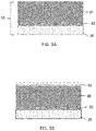
- the Figures 3A-3F are a simplified representation of a method of manufacturing a mechanical resonator 100 on a plate 10.
- the resonator is intended in particular to equip a regulating member of a timepiece and, according to this example, is in the form of a spiral spring 100 silicon which is intended to equip a balance wheel of a mechanical watch movement.
- Plate 10 is illustrated in Figure 3A as an SOI (“silicon on insulator”) wafer and comprises a substrate or “handler” 20 bearing a sacrificial layer of silicon oxide (SiO 2 ) 30 and a layer of monocrystalline silicon 40.
- the substrate 20 may have a thickness of 500 ⁇ m
- sacrificial layer 30 may have a thickness of 2 ⁇ m
- silicon layer 40 may have a thickness of 120 ⁇ m.
- the monocrystalline silicon layer 40 can have any crystalline orientation.
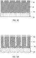
- a lithography step is shown to figure 3B and 3C .
- lithography is meant all the operations making it possible to transfer an image or pattern on or above the wafer 10 to the latter.
- the layer 40 is covered with a protective layer 50, for example of a polymerizable resin.
- This layer 50 is structured, typically by a photolithography step using an ultraviolet light source as well as, for example, a photo-mask (or another type of exposure mask) or a stepper and reticle system.
- This patterning by lithography forms the patterns for the plurality of resonators in layer 50, as illustrated in Fig. 3C .
- the patterns are machined, in particular etched, to form the plurality of resonators 100 in the layer 40.
- the etching can be performed by a deep reactive ion etching technique (also known by the acronym DRIE for “Deep Reactive Ion Etching”) .
- DRIE deep reactive ion etching technique
- the resonators are released from the substrate 20 by locally removing the sacrificial layer 30 or even by etching all or part of the silicon of the substrate or handler 20. Smoothing (not shown) of the etched surfaces can also take place before the release step, by for example by a thermal oxidation step followed by a deoxidation step, consisting for example of wet etching based on hydrofluoric acid (HF).
- HF hydrofluoric acid
- the turns 110 of the silicon resonator 100 are covered with a layer 120 of silicon oxide (Si02), typically by a thermal oxidation step to produce a thermocompensated resonator.
- This layer 120 which generally has a thickness of 2-5 ⁇ m, also affects the final stiffness of the resonator and therefore must be taken into account during the preceding steps.
- the various resonators formed in the wafer generally have a significant geometric dispersion between them and therefore a significant dispersion between their stiffnesses, notwithstanding that the steps of forming the patterns and machining/etching through these patterns are the same for all resonators.
- this dispersion of stiffness is even greater between the hairsprings of two wafers engraved at different times even if the same process specifications are used.
- the resonators obtained in step 3E on the wafer 10 in question can be deliberately formed with dimensions d which are greater than the dimensions necessary for obtaining a nominal or target stiffness.
- a correction is calculated and then implemented as precisely as possible in order to obtain a hairspring having characteristics, in particular of stiffness, which are as close as possible to a value target, predefined
- a qualitative approach in which we make a correction incrementally.
- a predefined correction dose is applied iteratively until a hairspring is obtained which exhibits, with a certain tolerance, the desired characteristics.
- correction dose we define, according to the type of correction used (removal or addition of material), a set of parameters and steps which lead to performing the same increment of correction, at each dose, i.e. i.e. to add an incremental amount of material or, if applicable, to remove an incremental amount of material.
- step c the incremental and predetermined quantity of material added or removed in step c is independent of the evaluation of the stiffness and/or of the dimension carried out in step b.
- hairsprings are produced with dimensions greater than the necessary dimensions, we evaluate during step b. the stiffness of at least one hairspring, according to one of the methods which will be described below. This evaluation, according to this example, will indicate too much stiffness compared to a target value. The correction is then carried out, which will be a removal of an incremental quantity of material on the hairspring, homogeneous or heterogeneous along the turn.
- Such removal of material can thus be carried out, by carrying out a thermal oxidation step followed by a deoxidation step allowing a fine and precise removal of the quantity of material.
- the dimensional difference is converted into an oxide thickness value to be grown knowing that approximately 44% of the oxide layer will be below the original surface and 56% above. above. Since the growth of the thermal oxide layer can be precisely controlled, the amount of material removed is precisely repeatable and controllable. Typically, one can target the growth of a layer between 50 nm and 250 nm, preferably 100 nm.
- the stiffness of the hairspring evaluated during the first iteration is evaluated again.
- the evaluated stiffness is again compared with the target stiffness.
- a new correction is carried out according to the planned increment, until a conforming stiffness is obtained.
- Compliant implies a stiffness that is within a predefined tolerance range, predicted to correspond to a certain range of stiffness. It is also possible to provide a class defined by a conforming stiffness. If, in step b, the hairspring in question has consistent stiffness, no correction is made.
- the plate can be considered compliant (according to the sampling of hairsprings considered on the wafer, as mentioned below) and suitable for use in the rest of the production flow.
- a dynamic evaluation can be carried out by coupling the hairspring to a reference balance wheel whose inertia is known. Measuring the frequency of the assembly makes it possible to deduce the stiffness of the hairspring precisely. This evaluation can be carried out on the wafer or by detaching the hairspring from the wafer.
- the references and prior art given above, provide details on this method. The evaluation is done simply by qualitatively comparing whether the frequency obtained, by associating the hairspring with a balance wheel of predetermined inertia, is within an acceptable, predefined tolerance range.
- the measurement of the stiffness of the hairspring can be carried out in a so-called static manner, that is to say without causing the hairspring to oscillate, but by determining its torque.
- static manner that is to say without causing the hairspring to oscillate, but by determining its torque.
- FIG. 4 An alternative to the method described in the latter document consists in carrying out a torque measurement using a rheometer, as marketed by the company Anton Paar.
- a device provided for this purpose is illustrated in the figure 4 .
- the hairspring 200 it makes it possible to place the hairspring 200 to be evaluated on a resting 202, and to position it in such a way that that it can be fixed at its last turn by a holding member 204. Once the last turn is fixed, the mounting 202 is moved away from the hairspring 200 which is thus completely free of any elastic constraint. The head of the rheometer 206 is then positioned opposite the ferrule of the hairspring.
- the protocol which has just been described has the advantage of not constraining the spiral spring in a parasitic manner during the measurement, in particular out of plane, which would disturb the measurement of the torque.
- the corrections can be differentiated by region, if the results obtained vary from one hairspring to another. It is thus possible to reduce the standard deviation of the dispersion of the stiffnesses.
- step b. indicates that a hairspring is compliant
- the validation of a wafer can be subject to the condition that several hairsprings, possibly in different regions of the wafer, are all compliant.
- the correction step then consists in adding material, as for example described in the document EP3181939 aforementioned.
- an oxidation step can be provided in order to form a layer of silicon oxide. It is possible to provide for this purpose a heat treatment between 800° C. and 1200° C. under an oxidizing atmosphere in the dry (in the presence of oxygen) or wet (in the presence of oxygen and water vapour) atmosphere.
- N-type or P-type doping can be provided.
- N-type doping can be carried out using at least one element from among: antimony Sb, arsenic As, or phosphorus P.
- P-type doping can be obtained for example by using boron B.
Landscapes
- Engineering & Computer Science (AREA)
- Physics & Mathematics (AREA)
- General Physics & Mathematics (AREA)
- Manufacturing & Machinery (AREA)
- Mechanical Engineering (AREA)
- Microelectronics & Electronic Packaging (AREA)
- Micromachines (AREA)
- Sampling And Sample Adjustment (AREA)
Applications Claiming Priority (1)
| Application Number | Priority Date | Filing Date | Title |
|---|---|---|---|
| EP21152156.2A EP4030241A1 (de) | 2021-01-18 | 2021-01-18 | Verfahren zur herstellung von uhrwerk-spiralfedern |
Publications (1)
| Publication Number | Publication Date |
|---|---|
| EP4030242A1 true EP4030242A1 (de) | 2022-07-20 |
Family
ID=74187197
Family Applications (2)
| Application Number | Title | Priority Date | Filing Date |
|---|---|---|---|
| EP21152156.2A Withdrawn EP4030241A1 (de) | 2021-01-18 | 2021-01-18 | Verfahren zur herstellung von uhrwerk-spiralfedern |
| EP22151557.0A Pending EP4030242A1 (de) | 2021-01-18 | 2022-01-14 | Verfahren zur herstellung von uhrwerks-spiralfedern |
Family Applications Before (1)
| Application Number | Title | Priority Date | Filing Date |
|---|---|---|---|
| EP21152156.2A Withdrawn EP4030241A1 (de) | 2021-01-18 | 2021-01-18 | Verfahren zur herstellung von uhrwerk-spiralfedern |
Country Status (1)
| Country | Link |
|---|---|
| EP (2) | EP4030241A1 (de) |
Cited By (1)
| Publication number | Priority date | Publication date | Assignee | Title |
|---|---|---|---|---|
| EP4553586A1 (de) | 2023-11-08 | 2025-05-14 | Patek Philippe SA Genève | Verfahren zur herstellung einer rückstellfeder mit genauer steifigkeit für einen uhrresonator |
Citations (10)
| Publication number | Priority date | Publication date | Assignee | Title |
|---|---|---|---|---|
| EP1422436A1 (de) | 2002-11-25 | 2004-05-26 | CSEM Centre Suisse d'Electronique et de Microtechnique SA | Spiraluhrwerkfeder und Verfahren zu deren Herstellung |
| EP2215531A1 (de) | 2007-11-28 | 2010-08-11 | Manufacture et fabrique de montres et chronomètres Ulysse Nardin Le Locle SA | Mechanischer oszillator mit einem optimierten thermoelastischen koeffizienten |
| CH702708B1 (fr) * | 2007-04-27 | 2011-08-31 | Sigatec S A | Ensemble oscillateur balancier-spiral avec éléments détachables et procédé d'ajustement de sa fréquence d'oscillation. |
| WO2015113973A1 (fr) | 2014-01-29 | 2015-08-06 | Cartier Création Studio Sa | Ressort spiral thermocompensé en céramique comprenant l' élément silicium dans sa composition et son procédé de réglage |
| WO2016128694A1 (fr) | 2015-02-13 | 2016-08-18 | Tronic's Microsystems | Oscillateur mécanique et procédé de réalisation associe |
| EP3181938A1 (de) | 2015-12-18 | 2017-06-21 | CSEM Centre Suisse d'Electronique et de Microtechnique SA - Recherche et Développement | Herstellungsverfahren einer spiralfeder mit einer vorbestimmten steifigkeit durch wegnahme von material |
| EP3181939A1 (de) | 2015-12-18 | 2017-06-21 | CSEM Centre Suisse d'Electronique et de Microtechnique SA - Recherche et Développement | Herstellungsverfahren einer spiralfeder mit einer vorbestimmten steifigkeit durch zugabe von material |
| CH711962A2 (fr) * | 2015-12-18 | 2017-06-30 | Csem Centre Suisse D'electronique Et De Microtechnique Sa – Rech Et Développement | Procédé de fabrication d'un spiral d'une raideur prédéterminée par retrait localisé de matière. |
| WO2019180558A1 (fr) * | 2018-03-20 | 2019-09-26 | Patek Philippe Sa Geneve | Procede de fabrication de spiraux horlogers thermocompenses de raideur precise |
| EP3654111A1 (de) | 2018-11-15 | 2020-05-20 | Nivarox-FAR S.A. | Verfahren zur messung des drehmoments einer spiralfeder einer uhr |
-
2021
- 2021-01-18 EP EP21152156.2A patent/EP4030241A1/de not_active Withdrawn
-
2022
- 2022-01-14 EP EP22151557.0A patent/EP4030242A1/de active Pending
Patent Citations (10)
| Publication number | Priority date | Publication date | Assignee | Title |
|---|---|---|---|---|
| EP1422436A1 (de) | 2002-11-25 | 2004-05-26 | CSEM Centre Suisse d'Electronique et de Microtechnique SA | Spiraluhrwerkfeder und Verfahren zu deren Herstellung |
| CH702708B1 (fr) * | 2007-04-27 | 2011-08-31 | Sigatec S A | Ensemble oscillateur balancier-spiral avec éléments détachables et procédé d'ajustement de sa fréquence d'oscillation. |
| EP2215531A1 (de) | 2007-11-28 | 2010-08-11 | Manufacture et fabrique de montres et chronomètres Ulysse Nardin Le Locle SA | Mechanischer oszillator mit einem optimierten thermoelastischen koeffizienten |
| WO2015113973A1 (fr) | 2014-01-29 | 2015-08-06 | Cartier Création Studio Sa | Ressort spiral thermocompensé en céramique comprenant l' élément silicium dans sa composition et son procédé de réglage |
| WO2016128694A1 (fr) | 2015-02-13 | 2016-08-18 | Tronic's Microsystems | Oscillateur mécanique et procédé de réalisation associe |
| EP3181938A1 (de) | 2015-12-18 | 2017-06-21 | CSEM Centre Suisse d'Electronique et de Microtechnique SA - Recherche et Développement | Herstellungsverfahren einer spiralfeder mit einer vorbestimmten steifigkeit durch wegnahme von material |
| EP3181939A1 (de) | 2015-12-18 | 2017-06-21 | CSEM Centre Suisse d'Electronique et de Microtechnique SA - Recherche et Développement | Herstellungsverfahren einer spiralfeder mit einer vorbestimmten steifigkeit durch zugabe von material |
| CH711962A2 (fr) * | 2015-12-18 | 2017-06-30 | Csem Centre Suisse D'electronique Et De Microtechnique Sa – Rech Et Développement | Procédé de fabrication d'un spiral d'une raideur prédéterminée par retrait localisé de matière. |
| WO2019180558A1 (fr) * | 2018-03-20 | 2019-09-26 | Patek Philippe Sa Geneve | Procede de fabrication de spiraux horlogers thermocompenses de raideur precise |
| EP3654111A1 (de) | 2018-11-15 | 2020-05-20 | Nivarox-FAR S.A. | Verfahren zur messung des drehmoments einer spiralfeder einer uhr |
Non-Patent Citations (1)
| Title |
|---|
| M. VERMOT ET AL., TRAITÉ DE CONSTRUCTION HORLOGÈRE, 2011, pages 178 - 179 |
Cited By (1)
| Publication number | Priority date | Publication date | Assignee | Title |
|---|---|---|---|---|
| EP4553586A1 (de) | 2023-11-08 | 2025-05-14 | Patek Philippe SA Genève | Verfahren zur herstellung einer rückstellfeder mit genauer steifigkeit für einen uhrresonator |
Also Published As
| Publication number | Publication date |
|---|---|
| EP4030241A1 (de) | 2022-07-20 |
Similar Documents
| Publication | Publication Date | Title |
|---|---|---|
| EP4031936B1 (de) | Verfahren zur herstellung einer mehrzahl von resonatoren in einem wafer | |
| EP3181938B1 (de) | Herstellungsverfahren einer spiralfeder mit einer vorbestimmten steifigkeit durch wegnahme von material | |
| EP3181940B2 (de) | Herstellungsverfahren einer spiralfeder mit einer vorbestimmten steifigkeit durch lokalisierte wegnahme von material | |
| EP1519250B1 (de) | Spiralfeder-Unruh-Resonator mit Thermokompensation | |
| EP3915788B1 (de) | Verfahren zur herstellung eines loses von uhrwerk-spiralfedern | |
| EP3769162A1 (de) | Verfahren zur herstellung von uhrenherstellungskomponenten aus silicium | |
| EP3769161B1 (de) | Herstellungsverfahren von thermokompensierten spiralen mit exakter steifigkeit | |
| EP2597536A1 (de) | Verbesserte Spiralfeder, und Herstellungsverfahren dieser Spiralfeder | |
| EP4030243A1 (de) | Verfahren zur kontrolle und zur herstellung von uhrwerk-spiralfedern | |
| EP4030242A1 (de) | Verfahren zur herstellung von uhrwerks-spiralfedern | |
| EP3982205A1 (de) | Verfahren zur herstellung einer uhrfeder mit einer präzisen steifigkeit | |
| CH718081A2 (fr) | Élément élastique pour un système micromécanique. | |
| EP3304216B1 (de) | Thermokompensierte resonator für uhrwerk und verfahren zur herstellung einer solchen resonator | |
| WO2021170473A1 (fr) | Composant horloger en silicium pour pièce d'horlogerie | |
| CH714815A2 (fr) | Procédé de fabrication d’un spiral en silicium pour l’horlogerie. | |
| CH716696A2 (fr) | Procédé de fabrication de spiraux horlogers. | |
| WO2024017847A1 (fr) | Procédé de controle et de fabrication de ressorts spiraux d'horlogerie | |
| EP4553586A1 (de) | Verfahren zur herstellung einer rückstellfeder mit genauer steifigkeit für einen uhrresonator | |
| EP4303668A1 (de) | Verfahren zur bestimmung der steifigkeit einer spiralfeder | |
| EP3534222A1 (de) | Herstellungsverfahren eines thermokompensierten oszillators | |
| EP4212965A1 (de) | Verfahren zur begrenzung der verformung einer uhrenkomponente aus silizium | |
| CH719361A2 (fr) | Procédé de limitation de la déformation d'une pièce d'horlogerie en silicium au cours d'une oxydation thermique. | |
| HK40100807A (en) | Method for monitoring and manufacturing timepiece hairsprings | |
| EP4453665A1 (de) | Verfahren zum testen und herstellen von ausgleichsfedern für uhren | |
| CH719864A2 (fr) | Dispositif de détermination de la raideur d'un spiral. |
Legal Events
| Date | Code | Title | Description |
|---|---|---|---|
| PUAI | Public reference made under article 153(3) epc to a published international application that has entered the european phase |
Free format text: ORIGINAL CODE: 0009012 |
|
| STAA | Information on the status of an ep patent application or granted ep patent |
Free format text: STATUS: THE APPLICATION HAS BEEN PUBLISHED |
|
| AK | Designated contracting states |
Kind code of ref document: A1 Designated state(s): AL AT BE BG CH CY CZ DE DK EE ES FI FR GB GR HR HU IE IS IT LI LT LU LV MC MK MT NL NO PL PT RO RS SE SI SK SM TR |
|
| STAA | Information on the status of an ep patent application or granted ep patent |
Free format text: STATUS: REQUEST FOR EXAMINATION WAS MADE |
|
| 17P | Request for examination filed |
Effective date: 20230106 |
|
| RBV | Designated contracting states (corrected) |
Designated state(s): AL AT BE BG CH CY CZ DE DK EE ES FI FR GB GR HR HU IE IS IT LI LT LU LV MC MK MT NL NO PL PT RO RS SE SI SK SM TR |
|
| STAA | Information on the status of an ep patent application or granted ep patent |
Free format text: STATUS: EXAMINATION IS IN PROGRESS |
|
| 17Q | First examination report despatched |
Effective date: 20241218 |