EP4030003A1 - System und verfahren zur steuerung eines hydraulischen baggers - Google Patents
System und verfahren zur steuerung eines hydraulischen baggers Download PDFInfo
- Publication number
- EP4030003A1 EP4030003A1 EP19944808.5A EP19944808A EP4030003A1 EP 4030003 A1 EP4030003 A1 EP 4030003A1 EP 19944808 A EP19944808 A EP 19944808A EP 4030003 A1 EP4030003 A1 EP 4030003A1
- Authority
- EP
- European Patent Office
- Prior art keywords
- main pump
- engine
- hydraulic excavator
- pump power
- controller
- Prior art date
- Legal status (The legal status is an assumption and is not a legal conclusion. Google has not performed a legal analysis and makes no representation as to the accuracy of the status listed.)
- Granted
Links
Images


Classifications
-
- E—FIXED CONSTRUCTIONS
- E02—HYDRAULIC ENGINEERING; FOUNDATIONS; SOIL SHIFTING
- E02F—DREDGING; SOIL-SHIFTING
- E02F9/00—Component parts of dredgers or soil-shifting machines, not restricted to one of the kinds covered by groups E02F3/00 - E02F7/00
- E02F9/20—Drives; Control devices
- E02F9/22—Hydraulic or pneumatic drives
- E02F9/2246—Control of prime movers, e.g. depending on the hydraulic load of work tools
-
- E—FIXED CONSTRUCTIONS
- E02—HYDRAULIC ENGINEERING; FOUNDATIONS; SOIL SHIFTING
- E02F—DREDGING; SOIL-SHIFTING
- E02F9/00—Component parts of dredgers or soil-shifting machines, not restricted to one of the kinds covered by groups E02F3/00 - E02F7/00
- E02F9/20—Drives; Control devices
- E02F9/22—Hydraulic or pneumatic drives
- E02F9/2221—Control of flow rate; Load sensing arrangements
- E02F9/2232—Control of flow rate; Load sensing arrangements using one or more variable displacement pumps
- E02F9/2235—Control of flow rate; Load sensing arrangements using one or more variable displacement pumps including an electronic controller
-
- E—FIXED CONSTRUCTIONS
- E02—HYDRAULIC ENGINEERING; FOUNDATIONS; SOIL SHIFTING
- E02F—DREDGING; SOIL-SHIFTING
- E02F9/00—Component parts of dredgers or soil-shifting machines, not restricted to one of the kinds covered by groups E02F3/00 - E02F7/00
- E02F9/20—Drives; Control devices
- E02F9/22—Hydraulic or pneumatic drives
- E02F9/2278—Hydraulic circuits
- E02F9/2282—Systems using center bypass type changeover valves
-
- E—FIXED CONSTRUCTIONS
- E02—HYDRAULIC ENGINEERING; FOUNDATIONS; SOIL SHIFTING
- E02F—DREDGING; SOIL-SHIFTING
- E02F9/00—Component parts of dredgers or soil-shifting machines, not restricted to one of the kinds covered by groups E02F3/00 - E02F7/00
- E02F9/20—Drives; Control devices
- E02F9/22—Hydraulic or pneumatic drives
- E02F9/2278—Hydraulic circuits
- E02F9/2285—Pilot-operated systems
-
- E—FIXED CONSTRUCTIONS
- E02—HYDRAULIC ENGINEERING; FOUNDATIONS; SOIL SHIFTING
- E02F—DREDGING; SOIL-SHIFTING
- E02F9/00—Component parts of dredgers or soil-shifting machines, not restricted to one of the kinds covered by groups E02F3/00 - E02F7/00
- E02F9/20—Drives; Control devices
- E02F9/22—Hydraulic or pneumatic drives
- E02F9/2278—Hydraulic circuits
- E02F9/2296—Systems with a variable displacement pump
Definitions
- the present invention relates to a hydraulic excavator control system and method, and belongs to the technical field of hydraulic excavators.
- the purpose of the present invention is to overcome disadvantages in the prior at and provide a hydraulic excavator control system and method to solve the technical problems of reduction of the working efficiency when the engine is suddenly loaded in a low load state and the occurrence of black smoke when the engine is suddenly loaded in an idle state.
- the present invention provides a hydraulic excavator control method, including the following steps:
- the oil path pressure signal includes a main oil path pressure value of the hydraulic excavator and each pilot pressure value corresponding to a current action of the hydraulic excavator.
- the time for the engine ECM to start to adjust the engine oil injection quantity is ahead of the time for the controller to start to adjust the main pump power by 0.05-0.6 second.
- the present invention provides a hydraulic excavator control system including a controller, an engine ECM, and an oil path pressure collection unit, where the engine ECM and the oil path pressure collection unit are respectively communicationally connected to the controller;
- the controller is communicationally connected to the engine ECM using a CAN bus.
- the oil path pressure collection unit includes a first pressure sensor configured to collect a main oil path pressure value of the hydraulic excavator and a second pressure sensor configured to collect each pilot pressure value corresponding to a current action of the hydraulic excavator.
- the beneficial effects achieved by the present invention are the time for the engine ECM to start to adjust the engine oil injection quantity is earlier than the time for adjusting the main pump to the required main pump power, so as to greatly reduce a loading response time of the engine, improve a working efficiency of the whole machine, avoid the problem of black smoke from idle loading, and may further reduce an idle rotation speed of the engine and reduce fuel oil consumption.
- the control method further has advantages of simple implementations, low costs, and high reliability.
- FIG. 1 is a flowchart of a hydraulic excavator control method according to an embodiment of the present invention.
- the method mainly includes the following steps: collecting a main oil path pressure value of the hydraulic excavator and each pilot pressure value corresponding to a current action of the hydraulic excavator; obtaining, by the controller, a required main pump power according to the main oil path pressure value and each pilot pressure value corresponding to the current action of the hydraulic excavator, and sending the required main pump power to an engine ECM; the controller being capable of adjusting the main pump power according to the required main pump power; the engine ECM being capable of adjusting an engine oil injection quantity according to the required main pump power, and the time for the engine ECM to start to adjust the engine oil injection being earlier than the time for the controller to start to adjust the main pump power.
- the time for the engine ECM to start to adjust the engine oil injection being earlier than the time for the controller to start to adjust the main pump power can greatly reduce a loading response time of the engine, improve a working efficiency of the whole machine, avoid the problem of black smoke from idle loading, and may further reduce an idle rotation speed of the engine and reduce fuel oil consumption.
- the control method further has advantages of simple implementations, low costs, and high reliability.
- the time for the engine ECM to start to adjust the engine oil injection quantity is ahead of the time for the controller to start to adjust the main pump power by 0.05-0.6 second, which matches and is consistent with the hydraulic system requirements, and improves the working efficiency of the entire machine by 1-5%.
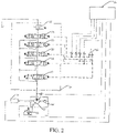
- FIG. 2 is a hydraulic principle diagram of a hydraulic excavator control system according to an embodiment of the present invention.
- the system includes an engine 10, a main pump 11, a pilot pump 12, an electromagnetic proportional valve 13, a main value 14, a hydraulic pilot handle 15, a controller 16, a first pressure collection unit, and a second pressure collection unit.
- the engine 10 is connected to the main pump 11 and the pilot pump 12 for providing power for the main pump 11 and the pilot pump 12.
- the main valve 14 includes a traveling valve core 17, a rotation value core 18, a moving arm valve core 19, a scraper pan valve core 20, and a pan rod valve core 21. After an outlet of the main pump 11 is connected to an inlet of the main valve 14 through a pipeline, it is sequentially connected to the traveling valve core 17, the rotation value core 18, the moving arm valve core 19, the scraper pan valve core 20, and the pan rod valve core 21 for providing oil for each action valve core and constituting a main oil path; an oil return port of the main valve 14 is connected to an oil tank after passing through an electromagnetic valve 22.
- the pilot pump 12 is connected to an inlet of the electromagnetic proportional valve 13; a path of an outlet of the electromagnetic proportional valve 13 is connected to a tilting plate adjuster control port of the main pump 11.
- the hydraulic pilot handle 15 is separately connected to a pilot control oil port of each action valve core for controlling connection and disconnection of each action valve core.
- the first pressure collection unit and the second pressure collection unit are respectively in communicative connection to the controller 16.
- the first pressure collection unit is used for collecting the main oil path pressure value of the hydraulic excavator;
- the second pressure collection unit is used for collecting the pilot control oil path pressure value of each action valve core;
- the controller 16 can obtain the required main pump power according to the main oil path pressure value and the pilot control oil path pressure value of each action valve core and adjust the power of the main pump 11 of the hydraulic excavator according to the required main pump power.
- the controller 16 is communicationally connected to the engine ECM for delivering the required main pump power to the engine ECM of the hydraulic excavator.
- FIG. 3 is a relation diagram between an engine oil injection quantity of a hydraulic excavator and time in the prior art.
- FIG. 4 is a relation diagram between an engine oil injection quantity of a hydraulic excavator and time according to an embodiment of the present invention.
- a hydraulic excavator provided in embodiment II of the present invention can greatly reduce a loading response time of the engine 10, so as to improve a working efficiency of the whole machine, and avoid the problem of black smoke from idle loading, and may further reduce an idle rotation speed of the engine 10 and reduce fuel oil consumption.
- it further has advantages of simple implementations, low costs, and high reliability.
- the first pressure collection unit, the second pressure collection unit, and the engine ECM can be connected to the controller 16 through the CAN bus.
- the first pressure collection unit and the second pressure collection unit are pressure sensors; as shown in FIG. 2 , a pressure sensor is separately disposed on the pilot control oil path of the rotation value core 18, the moving arm valve core 19, the scraper pan valve core 20, and the pan rod valve core 21.
- the hydraulic excavator control system and method provided by the embodiment of the present invention includes: collecting a main oil path pressure value of the hydraulic excavator; obtaining, by a controller, a required main pump power according to the oil path pressure value; the controller being used for adjusting, according to the required main pump power, the power of the main pump and delivering the required main pump power to an engine ECM; the time for the engine ECM to start to adjust the engine oil injection being earlier than the time for the controller to start to adjust the main pump power so as to greatly reduce a loading response time of the engine, improve a working efficiency of the whole machine, avoid the problem of black smoke from idle loading, and further reduce an idle rotation speed of the engine and reduce fuel oil consumption.
- the control method further has advantages of simple implementations, low costs, and high reliability.
- each embodiment in this specification is described in a progressive manner; each embodiment mainly illustrates the difference from other embodiments; same and similar parts among the embodiments can refer to one another.
- the control method disclosed in the embodiments since the adopted control device partially corresponds to the device disclosed by the embodiments, the description of the control device involved therein is relatively simple and the relevance can refer to the explanation of the device part.
Landscapes
- Engineering & Computer Science (AREA)
- Mining & Mineral Resources (AREA)
- Civil Engineering (AREA)
- General Engineering & Computer Science (AREA)
- Structural Engineering (AREA)
- Physics & Mathematics (AREA)
- Fluid Mechanics (AREA)
- Operation Control Of Excavators (AREA)
- Control Of Vehicle Engines Or Engines For Specific Uses (AREA)
- Fluid-Pressure Circuits (AREA)
Applications Claiming Priority (1)
| Application Number | Priority Date | Filing Date | Title |
|---|---|---|---|
| PCT/CN2019/105276 WO2021046736A1 (zh) | 2019-09-11 | 2019-09-11 | 一种液压挖掘机控制系统及方法 |
Publications (3)
| Publication Number | Publication Date |
|---|---|
| EP4030003A1 true EP4030003A1 (de) | 2022-07-20 |
| EP4030003A4 EP4030003A4 (de) | 2022-10-12 |
| EP4030003B1 EP4030003B1 (de) | 2025-12-24 |
Family
ID=74866816
Family Applications (1)
| Application Number | Title | Priority Date | Filing Date |
|---|---|---|---|
| EP19944808.5A Active EP4030003B1 (de) | 2019-09-11 | 2019-09-11 | System und verfahren zur steuerung eines hydraulischen baggers |
Country Status (4)
| Country | Link |
|---|---|
| EP (1) | EP4030003B1 (de) |
| AU (1) | AU2019465349B2 (de) |
| CA (1) | CA3150007C (de) |
| WO (1) | WO2021046736A1 (de) |
Families Citing this family (5)
| Publication number | Priority date | Publication date | Assignee | Title |
|---|---|---|---|---|
| CN114045897B (zh) * | 2021-11-17 | 2023-06-02 | 江苏徐工工程机械研究院有限公司 | 一种正流量系统负载突变掉速控制方法、系统及挖掘机 |
| CN114687876B (zh) * | 2022-04-12 | 2023-01-06 | 潍柴动力股份有限公司 | 一种车辆怠速响应控制方法及车辆 |
| CN115324149B (zh) * | 2022-06-30 | 2023-10-27 | 三一重机有限公司 | 液压泵控制方法、装置及作业机械 |
| CN115110596B (zh) * | 2022-07-26 | 2023-12-19 | 山河智能装备股份有限公司 | 一种液压控制系统 |
| CN120042835A (zh) * | 2025-04-24 | 2025-05-27 | 柳工常州机械有限公司 | 一种电控先导装置及其控制方法 |
Family Cites Families (7)
| Publication number | Priority date | Publication date | Assignee | Title |
|---|---|---|---|---|
| JPH101978A (ja) * | 1996-06-13 | 1998-01-06 | Yutani Heavy Ind Ltd | バッテリ駆動の作業機械 |
| JP3925666B2 (ja) * | 1997-01-20 | 2007-06-06 | 株式会社小松製作所 | エンジンおよび可変容量型ポンプの制御装置 |
| US7797934B2 (en) * | 2007-04-30 | 2010-09-21 | Caterpillar Inc | Anti-stall system utilizing implement pilot relief |
| CN104074225B (zh) * | 2014-07-08 | 2017-02-08 | 湖南机电职业技术学院 | 一种液压挖掘机功率自适应控制系统 |
| CN104405002A (zh) * | 2014-10-10 | 2015-03-11 | 龙工(上海)挖掘机制造有限公司 | 一种提高液压挖掘机工作效率的控制装置及方法 |
| CN106869222A (zh) * | 2015-12-13 | 2017-06-20 | 姚秋丽 | 一种液压挖掘机工作装置多模式功率自动控制系统 |
| CN107044147B (zh) * | 2016-02-05 | 2023-02-14 | 贵州詹阳动力重工有限公司 | 一种电喷发动机轮式液压挖掘机行驶控制系统及控制方法 |
-
2019
- 2019-09-11 EP EP19944808.5A patent/EP4030003B1/de active Active
- 2019-09-11 WO PCT/CN2019/105276 patent/WO2021046736A1/zh not_active Ceased
- 2019-09-11 CA CA3150007A patent/CA3150007C/en active Active
- 2019-09-11 AU AU2019465349A patent/AU2019465349B2/en active Active
Also Published As
| Publication number | Publication date |
|---|---|
| WO2021046736A1 (zh) | 2021-03-18 |
| EP4030003B1 (de) | 2025-12-24 |
| CA3150007A1 (en) | 2021-03-18 |
| CA3150007C (en) | 2025-02-04 |
| AU2019465349A1 (en) | 2022-03-24 |
| AU2019465349B2 (en) | 2023-07-27 |
| EP4030003A4 (de) | 2022-10-12 |
Similar Documents
| Publication | Publication Date | Title |
|---|---|---|
| EP4030003A1 (de) | System und verfahren zur steuerung eines hydraulischen baggers | |
| CN100590307C (zh) | 一种液压动力系统的功率控制装置与方法 | |
| CN110644564B (zh) | 一种液压挖掘机控制系统及方法 | |
| CN103397678B (zh) | 一种发动机和液压泵的功率匹配节能系统及方法 | |
| CN100460649C (zh) | 一种挖掘机发动机转速控制方法 | |
| CN102733441B (zh) | 挖掘机升速控制节能系统及方法 | |
| US8312716B2 (en) | Hydraulic drive system | |
| CN107477051B (zh) | 载荷差异油电液复合背压调控双执行器系统 | |
| CN106050768A (zh) | 一种拖拉机电液悬挂系统 | |
| CN116696874B (zh) | 变转速压差调控负载敏感系统及其工程机械 | |
| CN201301467Y (zh) | 液压挖掘机液压及电子控制集成系统 | |
| CN101624941B (zh) | 工程机械节能控制方法和压力感应排量直接补偿柴油机恒阻力矩节能控制系统 | |
| CN102828834A (zh) | 发动机功率控制方法、发动机功率控制器和控制系统 | |
| CN114321046B (zh) | 一种液压系统、设备及其流量控制方法 | |
| CN208329024U (zh) | 一种装载机泵控混合动力液压系统 | |
| CN102864810B (zh) | 一种工程机械液压节能装置及控制方法和挖掘机 | |
| CN114722568B (zh) | 一种基于动力系统功率匹配与液压系统流量匹配的液压挖掘机的节能方法 | |
| CN114561985B (zh) | 一种基于负载循环变化的挖掘机油门控制方法及系统 | |
| CN116658493B (zh) | 基于变转速与变排量的负流量系统和电动工程机械装置 | |
| EP0881335A2 (de) | Motorsteuereinrichtung für eine Baumaschine | |
| CN103925090A (zh) | 动态节能系统及方法、以及工程机械 | |
| CN114370082B (zh) | 一种电动装载机的自动怠速控制系统及方法 | |
| JP2000161302A (ja) | 油圧建設機械のエンジンラグダウン防止装置 | |
| US12018460B2 (en) | Excavator | |
| US8925309B2 (en) | Method for predefining a rotational speed of a drive machine of a drive system |
Legal Events
| Date | Code | Title | Description |
|---|---|---|---|
| STAA | Information on the status of an ep patent application or granted ep patent |
Free format text: STATUS: THE INTERNATIONAL PUBLICATION HAS BEEN MADE |
|
| PUAI | Public reference made under article 153(3) epc to a published international application that has entered the european phase |
Free format text: ORIGINAL CODE: 0009012 |
|
| STAA | Information on the status of an ep patent application or granted ep patent |
Free format text: STATUS: REQUEST FOR EXAMINATION WAS MADE |
|
| 17P | Request for examination filed |
Effective date: 20220325 |
|
| AK | Designated contracting states |
Kind code of ref document: A1 Designated state(s): AL AT BE BG CH CY CZ DE DK EE ES FI FR GB GR HR HU IE IS IT LI LT LU LV MC MK MT NL NO PL PT RO RS SE SI SK SM TR |
|
| A4 | Supplementary search report drawn up and despatched |
Effective date: 20220908 |
|
| RIC1 | Information provided on ipc code assigned before grant |
Ipc: E02F 9/22 20060101AFI20220902BHEP |
|
| DAV | Request for validation of the european patent (deleted) | ||
| DAX | Request for extension of the european patent (deleted) | ||
| STAA | Information on the status of an ep patent application or granted ep patent |
Free format text: STATUS: EXAMINATION IS IN PROGRESS |
|
| 17Q | First examination report despatched |
Effective date: 20250717 |
|
| GRAP | Despatch of communication of intention to grant a patent |
Free format text: ORIGINAL CODE: EPIDOSNIGR1 |
|
| STAA | Information on the status of an ep patent application or granted ep patent |
Free format text: STATUS: GRANT OF PATENT IS INTENDED |
|
| INTG | Intention to grant announced |
Effective date: 20251010 |
|
| GRAS | Grant fee paid |
Free format text: ORIGINAL CODE: EPIDOSNIGR3 |
|
| GRAA | (expected) grant |
Free format text: ORIGINAL CODE: 0009210 |
|
| STAA | Information on the status of an ep patent application or granted ep patent |
Free format text: STATUS: THE PATENT HAS BEEN GRANTED |
|
| AK | Designated contracting states |
Kind code of ref document: B1 Designated state(s): AL AT BE BG CH CY CZ DE DK EE ES FI FR GB GR HR HU IE IS IT LI LT LU LV MC MK MT NL NO PL PT RO RS SE SI SK SM TR |
|
| REG | Reference to a national code |
Ref country code: CH Ref legal event code: F10 Free format text: ST27 STATUS EVENT CODE: U-0-0-F10-F00 (AS PROVIDED BY THE NATIONAL OFFICE) Effective date: 20251224 Ref country code: GB Ref legal event code: FG4D |
|
| REG | Reference to a national code |
Ref country code: DE Ref legal event code: R096 Ref document number: 602019079707 Country of ref document: DE |
|
| P01 | Opt-out of the competence of the unified patent court (upc) registered |
Free format text: CASE NUMBER: UPC_APP_0004086_4030003/2026 Effective date: 20260204 |