EP4029765A1 - Poutre de renfort d' ancrage de sièges et véhicule automobile associé - Google Patents
Poutre de renfort d' ancrage de sièges et véhicule automobile associé Download PDFInfo
- Publication number
- EP4029765A1 EP4029765A1 EP21215834.9A EP21215834A EP4029765A1 EP 4029765 A1 EP4029765 A1 EP 4029765A1 EP 21215834 A EP21215834 A EP 21215834A EP 4029765 A1 EP4029765 A1 EP 4029765A1
- Authority
- EP
- European Patent Office
- Prior art keywords
- vehicle
- seats
- section
- anchoring
- point
- Prior art date
- Legal status (The legal status is an assumption and is not a legal conclusion. Google has not performed a legal analysis and makes no representation as to the accuracy of the status listed.)
- Pending
Links
- 230000002787 reinforcement Effects 0.000 title claims abstract description 14
- 238000004873 anchoring Methods 0.000 title claims description 12
- 238000005452 bending Methods 0.000 claims abstract description 11
- 230000001105 regulatory effect Effects 0.000 description 6
- 230000003014 reinforcing effect Effects 0.000 description 4
- CURLTUGMZLYLDI-UHFFFAOYSA-N Carbon dioxide Chemical compound O=C=O CURLTUGMZLYLDI-UHFFFAOYSA-N 0.000 description 2
- 229910000831 Steel Inorganic materials 0.000 description 2
- 239000000463 material Substances 0.000 description 2
- 239000010959 steel Substances 0.000 description 2
- 229910002092 carbon dioxide Inorganic materials 0.000 description 1
- 239000001569 carbon dioxide Substances 0.000 description 1
- 230000003247 decreasing effect Effects 0.000 description 1
- 238000005265 energy consumption Methods 0.000 description 1
- 239000003344 environmental pollutant Substances 0.000 description 1
- 239000000446 fuel Substances 0.000 description 1
- 238000012423 maintenance Methods 0.000 description 1
- 239000002184 metal Substances 0.000 description 1
- 238000000034 method Methods 0.000 description 1
- 231100000719 pollutant Toxicity 0.000 description 1
- 238000005096 rolling process Methods 0.000 description 1
Images


Classifications
-
- B—PERFORMING OPERATIONS; TRANSPORTING
- B62—LAND VEHICLES FOR TRAVELLING OTHERWISE THAN ON RAILS
- B62D—MOTOR VEHICLES; TRAILERS
- B62D25/00—Superstructure or monocoque structure sub-units; Parts or details thereof not otherwise provided for
- B62D25/20—Floors or bottom sub-units
-
- B—PERFORMING OPERATIONS; TRANSPORTING
- B60—VEHICLES IN GENERAL
- B60N—SEATS SPECIALLY ADAPTED FOR VEHICLES; VEHICLE PASSENGER ACCOMMODATION NOT OTHERWISE PROVIDED FOR
- B60N2/00—Seats specially adapted for vehicles; Arrangement or mounting of seats in vehicles
- B60N2/005—Arrangement or mounting of seats in vehicles, e.g. dismountable auxiliary seats
-
- B—PERFORMING OPERATIONS; TRANSPORTING
- B60—VEHICLES IN GENERAL
- B60R—VEHICLES, VEHICLE FITTINGS, OR VEHICLE PARTS, NOT OTHERWISE PROVIDED FOR
- B60R22/00—Safety belts or body harnesses in vehicles
- B60R22/18—Anchoring devices
- B60R22/22—Anchoring devices secured to the vehicle floor
Definitions
- the present invention relates to seat anchoring elements for a motor vehicle, and more particularly to an anchoring reinforcement beam for seats and a vehicle comprising such a reinforcement beam.
- the safety belts fitted to motor vehicles hold the passengers on their seat during impacts suffered by the vehicles, and are generally fixed to the seats, the seats being secured to anchoring elements of the vehicle such as bodywork elements or elements of the vehicle frame.
- Vehicle seats can be interconnected and fixed to the vehicle by a central anchoring point, in particular the third row seats.
- the central anchor point In order to comply with the force and deformation constraints laid down by the regulatory texts, the central anchor point must have sufficient stiffness to satisfy the said constraints.
- a reinforcing beam is integrated under the floor of the vehicle in a transverse direction of the vehicle, the reinforcing beam connecting the central anchor point to areas of significant stiffness such as the side sills of the vehicle.
- Another solution consists in connecting the central anchor point to the cross members of the chassis by the reinforcing beam arranged in a longitudinal direction of the vehicle, under the floor of the vehicle.
- the reinforcement beam is generally oversized making the vehicle heavier so that the fuel consumption of the vehicle increases leading to an increase in pollutant emissions, such as carbon dioxide, or so that the electrical energy consumption of a hybrid vehicle or electric increases.
- the invention proposes an anchoring reinforcement beam for motor vehicle seats comprising an anchoring point for the seats.
- the section of the beam is variable along a longitudinal direction of the beam so that when a force is applied to the anchor point, the bending stress of each section of the beam is constant.
- the section of the beam is defined by its height and its width, the height of the beam being variable.
- the beam is hollowed out at its center.
- the invention also relates to a motor vehicle comprising an anchor reinforcement beam as defined above, and at least one seat, the seat being fixed to the anchor point of the beam.
- each end of the beam is connected to a structural element of the vehicle frame.
- the length of the beam is oriented in a transverse direction of the vehicle.
- each end of the beam is connected to a different side member of the vehicle.
- the length of the beam is oriented in a longitudinal direction of the vehicle.
- each end of the beam is connected to a different cross member of the vehicle
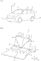
- the figure 1 illustrates a motor vehicle 1 oriented along a direct orthonormal reference R1(O, X, Y, Z).
- the reference R1 comprises an origin O, a first axis X oriented in a front-rear direction of the vehicle 1, a second axis Y in a transverse direction of the vehicle oriented towards the right of the vehicle 1 in the normal direction of travel of the vehicle 1, and a third axis Z along a vertical direction of the vehicle.
- Vehicle 1 comprises a first row of seats 2 located in the driving position of the vehicle, a second row of seats 3 and a third row of seats 4 located at the rear of vehicle 1.
- the picture 2 illustrates the third row of seats 4 fixed to the floor 5 of the chassis 6 of the vehicle 1.
- the third row of seats 4 comprises two seats 7, 8 each comprising a seat belt 9, 10.
- the seats 7, 8 are interconnected and fixed to the board 5 at different points of the vehicle 1.
- the two seats 7, 8 are in particular fixed to the floor 5 by a central fixing point 11 disposed between the two seats 7, 8, a closing loop 12 of each belt 9, 10 being connected to the central fixing point 11.
- the belts 9, 10 retain the passengers seated on the seats 7, 8, and in particular transmit the force resulting from the maintenance of the passengers on their seat to the central attachment point 10.
- FIGS. 3 and 4 respectively illustrate a partial view and a longitudinal view of the underside of the floor 5 of the vehicle 1 located under the third row of seats 4.
- the beam 13 of length L1, of height H1 and of constant width L2 is typically in the shape of a flattened ogive, as results from the equations presented below.
- the height H1 of the beam 13 is variable according to the longitudinal direction of the beam so that the section S1 of the beam, defined by the product of the variable height H1 by the width L2, is variable according to the longitudinal direction of the beam 13 .
- the length of the beam is oriented along the first axis X of the reference R1.
- Each end of the beam 13 is connected to a different structural element of the frame 5, for example to crosspieces 14, 15 of the frame 5.
- the length L1 of the beam 13 is oriented along the second axis Y of the reference R1, each end of the beam being for example connected to a different side member of the vehicle 1.
- the section of the beam 13 is determined so that when a force F is applied to the anchor point 12, the bending stress undergone by each section S1 of the beam is constant, the force F being for example the force enacted by the regulatory texts.
- the bending stress is for example chosen equal to the elastic limit of the material used to make the beam 13 and so that the maximum value of the deflection of the beam under the force F is compatible with the regulatory texts.
- the regulatory texts include, for example, the European regulation ECE14.
- the figure 5 shows an example of section S1 of beam 13.
- the beam 13 is oriented according to a second reference R2, the second orthonormal reference R2 comprising an origin O2, a first axis x, a second axis y and a third axis z coincident respectively with the first, second and third axes X, Y, Z of the first reference R1, the origin O2 of the second reference R2 being a point of connection of the beam 11 with a first crosspiece 14 and belonging to a plane of symmetry of the section of the beam.
- the figure 6 illustrates an example of a dimensioning model of the beam 13 when the force F is applied to the anchor point 12.
- the anchor point 12 is located at a first distance L 1 from the origin O2 and at a second distance L 2 from a point A of the second crosspiece 15, the length L1 being equal to the sum of the first and second distances L 1 , L 2 , point A being a connection point of beam 13 with second crosspiece 15.
- the effort F is modeled by the vector F including a horizontal component F X along the first axis x of the second frame R2, the horizontal component being oriented towards the front of the vehicle 1, and a vertical component FZ _ oriented along the third axis z of the second frame.
- the beam 13 is also subjected to the reaction forces R1 _ and R 2 located at points O2 and A.
- the figure 7 illustrates examples of longitudinal profiles C1, C2, C3, C4 of beam 13 as a function of the first axis x of the second reference mark R2 for different sheet thicknesses Ep in decreasing order, profile C1 having the greatest sheet thickness and the C4 profile having the lowest sheet thickness.
- the dimensioning of the anchoring reinforcement beam as described above makes it possible to fulfill regulatory requirements concerning seat anchorages while reducing the mass of said beam so that the vehicle 1 is lightened.
- the vehicle 1 consumes less energy to ensure its rolling.
Landscapes
- Engineering & Computer Science (AREA)
- Mechanical Engineering (AREA)
- Transportation (AREA)
- Aviation & Aerospace Engineering (AREA)
- Chemical & Material Sciences (AREA)
- Combustion & Propulsion (AREA)
- Body Structure For Vehicles (AREA)
Abstract
Description
- La présente invention concerne les éléments d'ancrage de sièges pour un véhicule automobile, et plus particulièrement une poutre de renfort d'ancrage pour sièges et un véhicule comprenant une telle poutre de renfort.
- Les ceintures de sécurité équipant des véhicules automobiles retiennent les passagers sur leur siège lors de chocs subis par les véhicules, et sont généralement fixées aux sièges, les sièges étant solidarisés à des éléments d'ancrage du véhicule tels que des éléments de carrosserie ou des éléments de châssis du véhicule.
- Les efforts auxquels les ceintures de sécurité et les éléments d'ancrage du véhicule doivent résister en cas de chocs sont imposés par des textes réglementaires, lesdits textes imposants en outre des valeurs de déformations mécaniques des éléments d'ancrage lors desdits chocs.
- Des sièges de véhicule peuvent être reliés entre eux et fixés au véhicule par un point d'ancrage central, notamment les sièges de troisième rangée.
- Afin de respecter les contraintes d'efforts et de déformations édictées par les textes réglementaires, le point d'ancrage central doit présenter une raideur suffisante pour satisfaire auxdites contraintes.
- Afin d'obtenir une raideur suffisante du point d'ancrage central, une poutre de renfort, généralement en acier, est intégrée sous le plancher du véhicule selon une direction transversale du véhicule, la poutre de renfort reliant le point d'ancrage central à des zones de raideur importante telles que les longerons latéraux du véhicule.
- Une autre solution consiste à relier le point d'ancrage central aux traverses du châssis par la poutre de renfort disposée selon une direction longitudinale du véhicule, sous le plancher du véhicule.
- La poutre de renfort est généralement surdimensionnée alourdissant le véhicule de sorte que la consommation de carburant du véhicule augmente entraînant une augmentation des émissions de polluants, tels que le dioxyde de carbone, ou de sorte que la consommation d'énergie électrique d'un véhicule hybride ou électrique augmente.
- Il est donc proposé de pallier tout ou partie des inconvénients précités et, en particulier, de diminuer la masse de la poutre de renfort.
- Au vu de ce qui précède, l'invention propose une poutre de renfort d'ancrage pour sièges de véhicule automobile comprenant un point d'ancrage des sièges.
- La section de la poutre est variable selon une direction longitudinale de la poutre de sorte que lorsqu'un effort est appliqué au point d'ancrage, la contrainte en flexion de chaque section de la poutre soit constante.
- Selon une caractéristique, la section de la poutre est définie par sa hauteur et sa largeur, la hauteur de la poutre étant variable.
- De préférence, la poutre est évidée en son centre.
- L'invention a également pour objet un véhicule automobile comprenant une poutre de renfort d'ancrage telle que définie précédemment, et au moins un siège, le siège étant fixé au point d'ancrage de la poutre.
- De préférence, chaque extrémité de la poutre est reliée à un élément structurel du châssis du véhicule.
- Selon une caractéristique, la longueur de la poutre est orientée selon une direction transversale du véhicule.
- Avantageusement, chaque extrémité de la poutre est reliée à un longeron latéral différent du véhicule.
- Selon une autre caractéristique, la longueur de la poutre est orientée selon une direction longitudinale du véhicule.
- De préférence, chaque extrémité de la poutre est reliée à une traverse différente du véhicule
- D'autres buts, caractéristiques et avantages de l'invention apparaîtront à la lecture de la description suivante, donnée uniquement à titre d'exemple non limitatif, et faite en référence aux dessins annexés sur lesquels :
- [
Fig 1 ] illustre schématiquement un véhicule automobile selon l'invention, - [
Fig 2 ] illustre schématiquement une troisième rangée de sièges du véhicule automobile selon l'invention, - [
Fig 3 ] - [
Fig 4 ] illustrent schématiquement le plancher du véhicule automobile selon l'invention, - [
Fig 5 ] illustre schématiquement une section d'une poutre de renfort d'ancrage selon l'invention, - [
Fig 6 ] illustre un exemple d'un modèle de dimensionnement de la poutre de renfort d'ancrage selon l'invention, et - [
Fig 7 ] illustre des exemples de profils longitudinaux de poutre de renfort d'ancrage selon l'invention. - La
figure 1 illustre un véhicule automobile 1 orienté selon un repère R1(O, X, Y, Z) orthonormé direct. - Le repère R1 comprend une origine O, un premier axe X orienté selon une direction avant-arrière du véhicule 1, un deuxième axe Y selon une direction transversale du véhicule orienté vers la droite du véhicule 1 selon le sens de roulage normal du véhicule 1, et un troisième axe Z selon une direction verticale du véhicule.
- Le véhicule 1 comprend une première rangée de sièges 2 située dans le poste de conduite du véhicule, une deuxième rangée de sièges 3 et une troisième rangée de sièges 4 située à l'arrière du véhicule 1.
- La
figure 2 illustre la troisième rangée de sièges 4 fixée sur le plancher 5 du châssis 6 du véhicule 1. - La troisième rangée de sièges 4 comprend deux sièges 7, 8 comprenant chacun une ceinture de sécurité 9, 10.
- Les sièges 7, 8 sont reliés entre eux et fixés au planche 5 en différents points du véhicule 1.
- Les deux sièges 7, 8 sont notamment fixés au plancher 5 par un point de fixation centrale 11 disposé entre les deux sièges 7, 8, une boucle de fermeture 12 de chaque ceinture 9, 10 étant reliée au point de fixation centrale 11.
- Lors d'un choc subi par le véhicule 1, les ceintures 9, 10 retiennent les passagers assis sur les sièges 7, 8, et transmettent notamment l'effort résultant du maintien des passagers sur leur siège au point de fixation centrale 10.
- On se réfère aux
figures 3 et 4 qui illustrent respectivement une vue partielle et une vue longitudinale du dessous du plancher 5 du véhicule 1 située sous la troisième rangée de sièges 4. - On retrouve le point de fixation centrale 11 du plancher 5 confondu avec un point d'ancrage 12 disposé sur une poutre de renfort d'ancrage 13.
- La poutre 13 de longueur L1, de hauteur H1 et de largeur constante L2 est typiquement en forme d'ogive aplatie, comme cela résulte des équations présentées ci-après.
- La hauteur H1 de la poutre 13 est variable selon la direction longitudinale de la poutre de sorte que la section S1 de la poutre, définie par le produit de la hauteur variable H1 par la largeur L2, soit variable selon la direction longitudinale de la poutre 13.
- La longueur de la poutre est orientée selon le premier axe X du repère R1.
- Chaque extrémité de la poutre 13 est reliée à un élément structurel différent du châssis 5, par exemple à des traverses 14, 15 du châssis 5.
- Selon un autre mode de réalisation, la longueur L1 de la poutre 13 est orientée selon le deuxième axe Y du repère R1, chaque extrémité de la poutre étant par exemple reliée à un longeron latéral différent du véhicule 1.
- La section de la poutre 13 est déterminée de sorte que lorsqu'un effort F est appliqué au point d'ancrage 12, la contrainte de flexion subie par chaque section S1 de la poutre soit constante, l'effort F étant par exemple l'effort édicté par les textes réglementaires.
- La contrainte en flexion est par exemple choisie égale à la limite élastique du matériau employé pour réaliser la poutre 13 et de sorte que la valeur maximale de la flèche de la poutre sous l'effort F soit compatible avec les textes réglementaires.
- Les textes réglementaires comprennent par exemple le règlement européen ECE14.
- A présent est détaillé un exemple de procédé de dimensionnement de la poutre 13.
- La
figure 5 illustre un exemple de la section S1 de la poutre 13. - La poutre 13, généralement en acier, est par exemple évidée en son centre et réalisée par emboutissage d'une feuille de tôle d'épaisseur Ep, la section S1 de la poutre étant rectangulaire.
- La poutre 13 est orientée selon un deuxième repère R2, le deuxième repère orthonormé R2 comprenant une origine O2, un premier axe x, un deuxième axe y et une troisième axe z confondus respectivement avec le premier, deuxième et troisième axes X, Y, Z du premier repère R1, l'origine O2 du deuxième repère R2 étant un point de liaison de la poutre 11 avec une première traverse 14 et appartenant à un plan de symétrie de la section de la poutre.
- La
figure 6 illustre un exemple d'un modèle de dimensionnement de la poutre 13 lorsque l'effort F est appliqué au point d'ancrage 12. - Le point d'ancrage 12 est situé à une première distance L1 de l'origine O2 et à une deuxième distance L2 d'un point A de la deuxième traverse 15, la longueur L1 étant égale à la somme des première et deuxième distances L1, L2, le point A étant un point de liaison de la poutre 13 avec la deuxième traverse 15.
- L'effort F est modélisé par le vecteur
F comprenant une composante horizontaleFX selon le premier axe x du deuxième repère R2, la composante horizontale étant orientée vers l'avant du véhicule 1, et une composante verticaleF Z orientée selon le troisième axe z du deuxième repère. - Comme la composante verticale
F Z est prépondérante pour le dimensionnement de la poutre 13 par rapport à la composante horizontaleFX , la composante horizontaleFX est négligée. - La poutre 13 est soumise en outre aux efforts de réaction
R 1 etR 2 situés aux points O2 et A. - Le moment d'inertie I O2y de la poutre 13 au point O2 par rapport au deuxième axe y du deuxième repère R2 est égal à :

- Le moment fléchissant Mƒc à un point C de coordonnée x1 appartenant à la section S1(x1) selon le premier axe x du deuxième repère R2 s'écrit :


- La contrainte de flexion σx au point C(x1) de la section S1(x1) en fonction du moment fléchissant Mƒc est égale à :

- Comme la contrainte en flexion σx est égale à la limite élastique σxmax du matériau utilisé pour réaliser la poutre 13, on pose :

- En remplaçant le moment d'inertie I O2y et le moment fléchissant Mƒc par leur expression dans l'équation (4), et en négligeant le terme Ep2H1 2 lors de développement du moment d'inertie I O2y , on obtient les équations suivantes :


- En résolvant les équations (6) et (7), et en conservant les solutions physiques, on obtient la hauteur H1 selon x1 de sorte que la contrainte en flexion σx de chaque section S1(x1) de la poutre soit constante et égale à la limite élastique σxmax pour l'effort verticale Fz :


- La
figure 7 illustre des exemples de profils longitudinaux C1, C2, C3, C4 de poutre 13 en fonction du premier axe x du deuxième repère R2 pour des épaisseurs de tôle Ep différentes selon un ordre décroissant, le profil C1 ayant l'épaisseur de tôle la plus importante et le profil C4 ayant l'épaisseur de tôle la plus faible. - On constate que la valeur la plus importante de la hauteur H1 de la poutre 13 est atteinte au point de coordonnée x12 du point d'ancrage 12.
- Le dimensionnement de la poutre de renfort d'ancrage comme décrit précédemment permet de remplir des prescriptions réglementaires concernant les ancrages de sièges tout en diminuant la masse de ladite poutre de sorte que la véhicule 1 soit allégée.
- Le véhicule 1 consomme moins d'énergie pour assurer son roulage.
- Lorsque la longueur L1 de la poutre 13 est orientée selon le deuxième axe Y du repère R1, les points O2 et A sont remplacés par des points de liaison de la poutre 13 avec des premier et deuxième longerons latéraux du véhicule 1.
Claims (9)
- Poutre (13) de renfort d'ancrage pour sièges (7, 8) de véhicule automobile (1) comprenant un point d'ancrage (12) des sièges, caractérisée en ce que la section (S1) de la poutre est variable selon une direction longitudinale (x) de la poutre de sorte que lorsqu'un effort (
F ) est appliqué au point d'ancrage, la contrainte en flexion (σx ) de chaque section de la poutre soit constante. - Poutre selon la revendication 1, dans laquelle la section (S1) de la poutre (13) est définie par sa hauteur (H1) et sa largeur (L2), la hauteur de la poutre étant variable.
- Poutre selon l'une des revendications 1 et 2, comprenant une poutre (13) évidée en son centre.
- Véhicule automobile (1) comprenant une poutre (13) de renfort d'ancrage selon l'une quelconques des revendications 1 à 3, et au moins un siège (7, 8), le siège étant fixé au point d'ancrage de la poutre.
- Véhicule selon la revendication 4, dans lequel chaque extrémité (O2, A) de la poutre (13) est reliée à un élément structurel (12, 13) du châssis (6) du véhicule.
- Véhicule selon l'une des revendications 4 et 5, dans lequel la longueur (L1) de la poutre (13) est orientée selon une direction transversale (Y) du véhicule.
- Véhicule selon la revendication 6, chaque extrémité de la poutre étant reliée à un longeron latéral différent du véhicule.
- Véhicule selon l'une des revendications 4 et 5, dans lequel la longueur (L1) de la poutre (13) est orientée selon une direction longitudinale (X) du véhicule.
- Véhicule selon la revendication 8, chaque extrémité de la poutre étant reliée à une traverse (14, 15) différente du véhicule.
Applications Claiming Priority (1)
| Application Number | Priority Date | Filing Date | Title |
|---|---|---|---|
| FR2100455A FR3118916B1 (fr) | 2021-01-18 | 2021-01-18 | Poutre de renfort d’ancrage de sièges et véhicule automobile associé |
Publications (1)
| Publication Number | Publication Date |
|---|---|
| EP4029765A1 true EP4029765A1 (fr) | 2022-07-20 |
Family
ID=74669155
Family Applications (1)
| Application Number | Title | Priority Date | Filing Date |
|---|---|---|---|
| EP21215834.9A Pending EP4029765A1 (fr) | 2021-01-18 | 2021-12-20 | Poutre de renfort d' ancrage de sièges et véhicule automobile associé |
Country Status (2)
| Country | Link |
|---|---|
| EP (1) | EP4029765A1 (fr) |
| FR (1) | FR3118916B1 (fr) |
Citations (5)
| Publication number | Priority date | Publication date | Assignee | Title |
|---|---|---|---|---|
| JP2012001023A (ja) * | 2010-06-14 | 2012-01-05 | Unipres Corp | 自動車の車体メンバー部材 |
| KR20130031949A (ko) * | 2011-09-22 | 2013-04-01 | 현대자동차주식회사 | 차량의 시트 크로스 멤버 |
| WO2016104078A1 (fr) * | 2014-12-22 | 2016-06-30 | 新日鐵住金株式会社 | Élément de structure |
| DE102019121705A1 (de) * | 2018-08-13 | 2020-02-13 | Suzuki Motor Corporation | Fahrzeugkarosserieteil, Fahrzeugkarosserieteileanordnung und Fahrzeugkarosseriekonstruktion |
| FR3095633A1 (fr) * | 2019-05-02 | 2020-11-06 | Psa Automobiles Sa | Traverse d’assise avant pour véhicule automobile à épaisseur variable |
-
2021
- 2021-01-18 FR FR2100455A patent/FR3118916B1/fr active Active
- 2021-12-20 EP EP21215834.9A patent/EP4029765A1/fr active Pending
Patent Citations (5)
| Publication number | Priority date | Publication date | Assignee | Title |
|---|---|---|---|---|
| JP2012001023A (ja) * | 2010-06-14 | 2012-01-05 | Unipres Corp | 自動車の車体メンバー部材 |
| KR20130031949A (ko) * | 2011-09-22 | 2013-04-01 | 현대자동차주식회사 | 차량의 시트 크로스 멤버 |
| WO2016104078A1 (fr) * | 2014-12-22 | 2016-06-30 | 新日鐵住金株式会社 | Élément de structure |
| DE102019121705A1 (de) * | 2018-08-13 | 2020-02-13 | Suzuki Motor Corporation | Fahrzeugkarosserieteil, Fahrzeugkarosserieteileanordnung und Fahrzeugkarosseriekonstruktion |
| FR3095633A1 (fr) * | 2019-05-02 | 2020-11-06 | Psa Automobiles Sa | Traverse d’assise avant pour véhicule automobile à épaisseur variable |
Also Published As
| Publication number | Publication date |
|---|---|
| FR3118916A1 (fr) | 2022-07-22 |
| FR3118916B1 (fr) | 2024-06-21 |
Similar Documents
| Publication | Publication Date | Title |
|---|---|---|
| US12077211B2 (en) | Lightweight vehicle | |
| US20170182873A1 (en) | Structural underbody support in a vehicle | |
| FR3083511A1 (fr) | Vehicule automobile avec appui de facade coulissant transversalement | |
| EP1434710B1 (fr) | Chassis de vehicule automobile | |
| EP3702222B1 (fr) | Dispositif de protection pour un véhicule automobile | |
| US7810870B2 (en) | Vehicle body structure | |
| FR3118916A1 (fr) | Poutre de renfort d’ancrage de sièges et véhicule automobile associé | |
| FR3076774A1 (fr) | Fixation de reservoir de carburant | |
| FR3140060A1 (fr) | Structure de véhicule avec renforts de traverse d’assise réduits. | |
| EP4359287B1 (fr) | Ensemble de structure de face avant pour un véhicule automobile | |
| EP1693283B1 (fr) | Structure avant de véhicule automobile | |
| EP3705347B1 (fr) | Véhicule doté d'un dispositif anti sous marinage amélioré | |
| EP1687179A1 (fr) | SIEGE POUR VEHICULE AUTOMOBILE, ET VEHICULE AUTOMOBILE EQUIPE D’UN TEL SIEGE | |
| CA3087374A1 (fr) | Dispositif de fixation pour la fixation d'une carrosserie mobile dans ou sur une zone de prise en charge d'un vehicule ainsi qu'un vehicule equipe d'un tel dispositif de fixation | |
| FR2986490A1 (fr) | Brancard de vehicule renforce pour choc frontal. | |
| CN219200847U (zh) | 乘用车测试用防翻架 | |
| FR2987322A1 (fr) | Assise de siege de vehicule comportant une traverse d'anti sous-marinage. | |
| FR3075746A1 (fr) | Structure de plancher mono-piece en matiere composite | |
| EP3863912B1 (fr) | Structure de plancher d'assise renforcee en cas de choc poteau | |
| EP1514770A1 (fr) | Soubassement pour véhicule automobile du type cabriolet ou coupé cabriolet | |
| FR3162721A1 (fr) | Structure de véhicule tricycle. | |
| JP3887289B2 (ja) | リヤシートの支持構造 | |
| FR3103748A1 (fr) | Element de plancher arriere de vehicule automobile | |
| CN120191192A (zh) | 车辆下部构造 | |
| EP1800997B1 (fr) | Soubassement de véhicule automobile et véhicule correspondant |
Legal Events
| Date | Code | Title | Description |
|---|---|---|---|
| PUAI | Public reference made under article 153(3) epc to a published international application that has entered the european phase |
Free format text: ORIGINAL CODE: 0009012 |
|
| STAA | Information on the status of an ep patent application or granted ep patent |
Free format text: STATUS: THE APPLICATION HAS BEEN PUBLISHED |
|
| AK | Designated contracting states |
Kind code of ref document: A1 Designated state(s): AL AT BE BG CH CY CZ DE DK EE ES FI FR GB GR HR HU IE IS IT LI LT LU LV MC MK MT NL NO PL PT RO RS SE SI SK SM TR |
|
| RAP3 | Party data changed (applicant data changed or rights of an application transferred) |
Owner name: RENAULT S.A.S |
|
| STAA | Information on the status of an ep patent application or granted ep patent |
Free format text: STATUS: REQUEST FOR EXAMINATION WAS MADE |
|
| 17P | Request for examination filed |
Effective date: 20230120 |
|
| RBV | Designated contracting states (corrected) |
Designated state(s): AL AT BE BG CH CY CZ DE DK EE ES FI FR GB GR HR HU IE IS IT LI LT LU LV MC MK MT NL NO PL PT RO RS SE SI SK SM TR |
|
| P01 | Opt-out of the competence of the unified patent court (upc) registered |
Effective date: 20230608 |
|
| STAA | Information on the status of an ep patent application or granted ep patent |
Free format text: STATUS: EXAMINATION IS IN PROGRESS |
|
| 17Q | First examination report despatched |
Effective date: 20241121 |