EP4029595A1 - Composite film and composite film manufacturing method - Google Patents
Composite film and composite film manufacturing method Download PDFInfo
- Publication number
- EP4029595A1 EP4029595A1 EP20862648.1A EP20862648A EP4029595A1 EP 4029595 A1 EP4029595 A1 EP 4029595A1 EP 20862648 A EP20862648 A EP 20862648A EP 4029595 A1 EP4029595 A1 EP 4029595A1
- Authority
- EP
- European Patent Office
- Prior art keywords
- membrane
- supporting
- separation layer
- supporting membrane
- sulfonated
- Prior art date
- Legal status (The legal status is an assumption and is not a legal conclusion. Google has not performed a legal analysis and makes no representation as to the accuracy of the status listed.)
- Pending
Links
- 239000002131 composite material Substances 0.000 title claims abstract description 76
- 238000004519 manufacturing process Methods 0.000 title claims description 7
- 239000012528 membrane Substances 0.000 claims abstract description 376
- 239000004372 Polyvinyl alcohol Substances 0.000 claims abstract description 102
- 229920002451 polyvinyl alcohol Polymers 0.000 claims abstract description 102
- 238000000926 separation method Methods 0.000 claims abstract description 90
- 239000004721 Polyphenylene oxide Substances 0.000 claims abstract description 86
- 229920006380 polyphenylene oxide Polymers 0.000 claims abstract description 86
- 125000000524 functional group Chemical group 0.000 claims abstract description 32
- QAOWNCQODCNURD-UHFFFAOYSA-N Sulfuric acid Chemical compound OS(O)(=O)=O QAOWNCQODCNURD-UHFFFAOYSA-N 0.000 claims description 78
- 238000000034 method Methods 0.000 claims description 70
- 125000000129 anionic group Chemical group 0.000 claims description 28
- 125000002091 cationic group Chemical group 0.000 claims description 28
- NINIDFKCEFEMDL-UHFFFAOYSA-N Sulfur Chemical compound [S] NINIDFKCEFEMDL-UHFFFAOYSA-N 0.000 claims description 16
- 125000000542 sulfonic acid group Chemical group 0.000 claims description 9
- 125000001453 quaternary ammonium group Chemical group 0.000 claims description 3
- XLYOFNOQVPJJNP-UHFFFAOYSA-N water Substances O XLYOFNOQVPJJNP-UHFFFAOYSA-N 0.000 description 67
- 239000012510 hollow fiber Substances 0.000 description 62
- 229920000642 polymer Polymers 0.000 description 36
- 239000000243 solution Substances 0.000 description 31
- 239000002904 solvent Substances 0.000 description 30
- 239000010408 film Substances 0.000 description 28
- SECXISVLQFMRJM-UHFFFAOYSA-N N-Methylpyrrolidone Chemical compound CN1CCCC1=O SECXISVLQFMRJM-UHFFFAOYSA-N 0.000 description 24
- 238000011156 evaluation Methods 0.000 description 24
- 239000011550 stock solution Substances 0.000 description 24
- OKKJLVBELUTLKV-UHFFFAOYSA-N Methanol Chemical compound OC OKKJLVBELUTLKV-UHFFFAOYSA-N 0.000 description 21
- 238000004132 cross linking Methods 0.000 description 21
- 238000005345 coagulation Methods 0.000 description 20
- 230000015271 coagulation Effects 0.000 description 20
- 238000006277 sulfonation reaction Methods 0.000 description 19
- 230000015572 biosynthetic process Effects 0.000 description 18
- 229920001577 copolymer Polymers 0.000 description 18
- 230000000052 comparative effect Effects 0.000 description 15
- 230000007547 defect Effects 0.000 description 14
- 230000008569 process Effects 0.000 description 13
- 239000003513 alkali Substances 0.000 description 12
- 239000000178 monomer Substances 0.000 description 12
- SXRSQZLOMIGNAQ-UHFFFAOYSA-N Glutaraldehyde Chemical compound O=CCCCC=O SXRSQZLOMIGNAQ-UHFFFAOYSA-N 0.000 description 11
- IJGRMHOSHXDMSA-UHFFFAOYSA-N Atomic nitrogen Chemical compound N#N IJGRMHOSHXDMSA-UHFFFAOYSA-N 0.000 description 10
- LFQSCWFLJHTTHZ-UHFFFAOYSA-N Ethanol Chemical compound CCO LFQSCWFLJHTTHZ-UHFFFAOYSA-N 0.000 description 10
- ZMXDDKWLCZADIW-UHFFFAOYSA-N N,N-Dimethylformamide Chemical compound CN(C)C=O ZMXDDKWLCZADIW-UHFFFAOYSA-N 0.000 description 10
- FAPWRFPIFSIZLT-UHFFFAOYSA-M Sodium chloride Chemical compound [Na+].[Cl-] FAPWRFPIFSIZLT-UHFFFAOYSA-M 0.000 description 10
- 239000007864 aqueous solution Substances 0.000 description 10
- PEDCQBHIVMGVHV-UHFFFAOYSA-N Glycerine Chemical compound OCC(O)CO PEDCQBHIVMGVHV-UHFFFAOYSA-N 0.000 description 9
- 238000000576 coating method Methods 0.000 description 9
- 239000011148 porous material Substances 0.000 description 9
- 238000012360 testing method Methods 0.000 description 9
- ZAMOUSCENKQFHK-UHFFFAOYSA-N Chlorine atom Chemical compound [Cl] ZAMOUSCENKQFHK-UHFFFAOYSA-N 0.000 description 8
- 150000001299 aldehydes Chemical class 0.000 description 8
- 238000006243 chemical reaction Methods 0.000 description 8
- 239000000460 chlorine Substances 0.000 description 8
- 229910052801 chlorine Inorganic materials 0.000 description 8
- 239000003431 cross linking reagent Substances 0.000 description 8
- RTZKZFJDLAIYFH-UHFFFAOYSA-N ether Substances CCOCC RTZKZFJDLAIYFH-UHFFFAOYSA-N 0.000 description 8
- 230000014759 maintenance of location Effects 0.000 description 8
- -1 poly(2,6-dimethyl-1,4-phenylene oxide) Polymers 0.000 description 8
- 229920000412 polyarylene Polymers 0.000 description 8
- 230000021736 acetylation Effects 0.000 description 7
- 238000006640 acetylation reaction Methods 0.000 description 7
- 239000003795 chemical substances by application Substances 0.000 description 7
- 238000011033 desalting Methods 0.000 description 7
- 238000001914 filtration Methods 0.000 description 7
- 238000005259 measurement Methods 0.000 description 7
- 238000006116 polymerization reaction Methods 0.000 description 7
- 239000000047 product Substances 0.000 description 7
- 238000007127 saponification reaction Methods 0.000 description 7
- 235000002639 sodium chloride Nutrition 0.000 description 7
- 238000001179 sorption measurement Methods 0.000 description 7
- 239000000126 substance Substances 0.000 description 7
- 238000005406 washing Methods 0.000 description 7
- XTXRWKRVRITETP-UHFFFAOYSA-N Vinyl acetate Chemical compound CC(=O)OC=C XTXRWKRVRITETP-UHFFFAOYSA-N 0.000 description 6
- 150000002500 ions Chemical class 0.000 description 6
- 238000005191 phase separation Methods 0.000 description 6
- 230000009467 reduction Effects 0.000 description 6
- XTHPWXDJESJLNJ-UHFFFAOYSA-N sulfurochloridic acid Chemical compound OS(Cl)(=O)=O XTHPWXDJESJLNJ-UHFFFAOYSA-N 0.000 description 6
- 238000005160 1H NMR spectroscopy Methods 0.000 description 5
- FXHOOIRPVKKKFG-UHFFFAOYSA-N N,N-Dimethylacetamide Chemical compound CN(C)C(C)=O FXHOOIRPVKKKFG-UHFFFAOYSA-N 0.000 description 5
- 238000004833 X-ray photoelectron spectroscopy Methods 0.000 description 5
- NJSSICCENMLTKO-HRCBOCMUSA-N [(1r,2s,4r,5r)-3-hydroxy-4-(4-methylphenyl)sulfonyloxy-6,8-dioxabicyclo[3.2.1]octan-2-yl] 4-methylbenzenesulfonate Chemical compound C1=CC(C)=CC=C1S(=O)(=O)O[C@H]1C(O)[C@@H](OS(=O)(=O)C=2C=CC(C)=CC=2)[C@@H]2OC[C@H]1O2 NJSSICCENMLTKO-HRCBOCMUSA-N 0.000 description 5
- 239000011248 coating agent Substances 0.000 description 5
- 238000001035 drying Methods 0.000 description 5
- 238000005227 gel permeation chromatography Methods 0.000 description 5
- 125000002887 hydroxy group Chemical group [H]O* 0.000 description 5
- 239000007788 liquid Substances 0.000 description 5
- 229910052757 nitrogen Inorganic materials 0.000 description 5
- 238000002360 preparation method Methods 0.000 description 5
- 239000011780 sodium chloride Substances 0.000 description 5
- HEDRZPFGACZZDS-UHFFFAOYSA-N Chloroform Chemical compound ClC(Cl)Cl HEDRZPFGACZZDS-UHFFFAOYSA-N 0.000 description 4
- CSNNHWWHGAXBCP-UHFFFAOYSA-L Magnesium sulfate Chemical compound [Mg+2].[O-][S+2]([O-])([O-])[O-] CSNNHWWHGAXBCP-UHFFFAOYSA-L 0.000 description 4
- 239000000835 fiber Substances 0.000 description 4
- 239000000203 mixture Substances 0.000 description 4
- 230000007935 neutral effect Effects 0.000 description 4
- 230000035699 permeability Effects 0.000 description 4
- BDHFUVZGWQCTTF-UHFFFAOYSA-M sulfonate Chemical compound [O-]S(=O)=O BDHFUVZGWQCTTF-UHFFFAOYSA-M 0.000 description 4
- 238000003786 synthesis reaction Methods 0.000 description 4
- 239000010409 thin film Substances 0.000 description 4
- QTBSBXVTEAMEQO-UHFFFAOYSA-N Acetic acid Chemical compound CC(O)=O QTBSBXVTEAMEQO-UHFFFAOYSA-N 0.000 description 3
- LYCAIKOWRPUZTN-UHFFFAOYSA-N Ethylene glycol Chemical compound OCCO LYCAIKOWRPUZTN-UHFFFAOYSA-N 0.000 description 3
- WSFSSNUMVMOOMR-UHFFFAOYSA-N Formaldehyde Chemical compound O=C WSFSSNUMVMOOMR-UHFFFAOYSA-N 0.000 description 3
- KFZMGEQAYNKOFK-UHFFFAOYSA-N Isopropanol Chemical compound CC(C)O KFZMGEQAYNKOFK-UHFFFAOYSA-N 0.000 description 3
- 239000002033 PVDF binder Substances 0.000 description 3
- CDBYLPFSWZWCQE-UHFFFAOYSA-L Sodium Carbonate Chemical compound [Na+].[Na+].[O-]C([O-])=O CDBYLPFSWZWCQE-UHFFFAOYSA-L 0.000 description 3
- HEMHJVSKTPXQMS-UHFFFAOYSA-M Sodium hydroxide Chemical compound [OH-].[Na+] HEMHJVSKTPXQMS-UHFFFAOYSA-M 0.000 description 3
- 239000002253 acid Substances 0.000 description 3
- 239000007795 chemical reaction product Substances 0.000 description 3
- KRKNYBCHXYNGOX-UHFFFAOYSA-N citric acid Chemical compound OC(=O)CC(O)(C(O)=O)CC(O)=O KRKNYBCHXYNGOX-UHFFFAOYSA-N 0.000 description 3
- MTHSVFCYNBDYFN-UHFFFAOYSA-N diethylene glycol Chemical compound OCCOCCO MTHSVFCYNBDYFN-UHFFFAOYSA-N 0.000 description 3
- 230000007613 environmental effect Effects 0.000 description 3
- 230000007062 hydrolysis Effects 0.000 description 3
- 238000006460 hydrolysis reaction Methods 0.000 description 3
- 238000007654 immersion Methods 0.000 description 3
- 239000012535 impurity Substances 0.000 description 3
- 238000003475 lamination Methods 0.000 description 3
- VLKZOEOYAKHREP-UHFFFAOYSA-N n-Hexane Chemical compound CCCCCC VLKZOEOYAKHREP-UHFFFAOYSA-N 0.000 description 3
- 125000001997 phenyl group Chemical group [H]C1=C([H])C([H])=C(*)C([H])=C1[H] 0.000 description 3
- 229920002981 polyvinylidene fluoride Polymers 0.000 description 3
- 230000009257 reactivity Effects 0.000 description 3
- 238000001223 reverse osmosis Methods 0.000 description 3
- 239000000758 substrate Substances 0.000 description 3
- JHUFGBSGINLPOW-UHFFFAOYSA-N 3-chloro-4-(trifluoromethoxy)benzoyl cyanide Chemical compound FC(F)(F)OC1=CC=C(C(=O)C#N)C=C1Cl JHUFGBSGINLPOW-UHFFFAOYSA-N 0.000 description 2
- IKHGUXGNUITLKF-UHFFFAOYSA-N Acetaldehyde Chemical compound CC=O IKHGUXGNUITLKF-UHFFFAOYSA-N 0.000 description 2
- IAZDPXIOMUYVGZ-UHFFFAOYSA-N Dimethylsulphoxide Chemical compound CS(C)=O IAZDPXIOMUYVGZ-UHFFFAOYSA-N 0.000 description 2
- VEXZGXHMUGYJMC-UHFFFAOYSA-N Hydrochloric acid Chemical compound Cl VEXZGXHMUGYJMC-UHFFFAOYSA-N 0.000 description 2
- 238000005481 NMR spectroscopy Methods 0.000 description 2
- 239000004696 Poly ether ether ketone Substances 0.000 description 2
- 239000004695 Polyether sulfone Substances 0.000 description 2
- 239000004734 Polyphenylene sulfide Substances 0.000 description 2
- 229920000491 Polyphenylsulfone Polymers 0.000 description 2
- WCUXLLCKKVVCTQ-UHFFFAOYSA-M Potassium chloride Chemical compound [Cl-].[K+] WCUXLLCKKVVCTQ-UHFFFAOYSA-M 0.000 description 2
- NBBJYMSMWIIQGU-UHFFFAOYSA-N Propionic aldehyde Chemical compound CCC=O NBBJYMSMWIIQGU-UHFFFAOYSA-N 0.000 description 2
- WYGWHHGCAGTUCH-ISLYRVAYSA-N V-65 Substances CC(C)CC(C)(C#N)\N=N\C(C)(C#N)CC(C)C WYGWHHGCAGTUCH-ISLYRVAYSA-N 0.000 description 2
- 238000006359 acetalization reaction Methods 0.000 description 2
- 239000000654 additive Substances 0.000 description 2
- HUMNYLRZRPPJDN-UHFFFAOYSA-N benzaldehyde Chemical compound O=CC1=CC=CC=C1 HUMNYLRZRPPJDN-UHFFFAOYSA-N 0.000 description 2
- 230000005540 biological transmission Effects 0.000 description 2
- 239000003054 catalyst Substances 0.000 description 2
- 239000011903 deuterated solvents Substances 0.000 description 2
- 238000009826 distribution Methods 0.000 description 2
- 229920006351 engineering plastic Polymers 0.000 description 2
- 239000003822 epoxy resin Substances 0.000 description 2
- 239000012530 fluid Substances 0.000 description 2
- 238000010528 free radical solution polymerization reaction Methods 0.000 description 2
- 239000007789 gas Substances 0.000 description 2
- LEQAOMBKQFMDFZ-UHFFFAOYSA-N glyoxal Chemical compound O=CC=O LEQAOMBKQFMDFZ-UHFFFAOYSA-N 0.000 description 2
- 229910052943 magnesium sulfate Inorganic materials 0.000 description 2
- 239000000463 material Substances 0.000 description 2
- 229910052751 metal Inorganic materials 0.000 description 2
- 239000002184 metal Substances 0.000 description 2
- 239000012046 mixed solvent Substances 0.000 description 2
- 238000005457 optimization Methods 0.000 description 2
- 229920002492 poly(sulfone) Polymers 0.000 description 2
- 229920000647 polyepoxide Polymers 0.000 description 2
- 229920000728 polyester Polymers 0.000 description 2
- 229920006393 polyether sulfone Polymers 0.000 description 2
- 229920002530 polyetherether ketone Polymers 0.000 description 2
- 229920000069 polyphenylene sulfide Polymers 0.000 description 2
- 229920001343 polytetrafluoroethylene Polymers 0.000 description 2
- 239000004810 polytetrafluoroethylene Substances 0.000 description 2
- 230000035484 reaction time Effects 0.000 description 2
- 150000003839 salts Chemical class 0.000 description 2
- 229910001415 sodium ion Inorganic materials 0.000 description 2
- 229910052717 sulfur Inorganic materials 0.000 description 2
- 239000011593 sulfur Substances 0.000 description 2
- AKEJUJNQAAGONA-UHFFFAOYSA-N sulfur trioxide Chemical compound O=S(=O)=O AKEJUJNQAAGONA-UHFFFAOYSA-N 0.000 description 2
- HIFJUMGIHIZEPX-UHFFFAOYSA-N sulfuric acid;sulfur trioxide Chemical compound O=S(=O)=O.OS(O)(=O)=O HIFJUMGIHIZEPX-UHFFFAOYSA-N 0.000 description 2
- BYEAHWXPCBROCE-UHFFFAOYSA-N 1,1,1,3,3,3-hexafluoropropan-2-ol Chemical compound FC(F)(F)C(O)C(F)(F)F BYEAHWXPCBROCE-UHFFFAOYSA-N 0.000 description 1
- PAWQVTBBRAZDMG-UHFFFAOYSA-N 2-(3-bromo-2-fluorophenyl)acetic acid Chemical compound OC(=O)CC1=CC=CC(Br)=C1F PAWQVTBBRAZDMG-UHFFFAOYSA-N 0.000 description 1
- WYGWHHGCAGTUCH-UHFFFAOYSA-N 2-[(2-cyano-4-methylpentan-2-yl)diazenyl]-2,4-dimethylpentanenitrile Chemical compound CC(C)CC(C)(C#N)N=NC(C)(C#N)CC(C)C WYGWHHGCAGTUCH-UHFFFAOYSA-N 0.000 description 1
- AIFLGMNWQFPTAJ-UHFFFAOYSA-J 2-hydroxypropanoate;titanium(4+) Chemical compound [Ti+4].CC(O)C([O-])=O.CC(O)C([O-])=O.CC(O)C([O-])=O.CC(O)C([O-])=O AIFLGMNWQFPTAJ-UHFFFAOYSA-J 0.000 description 1
- LSNNMFCWUKXFEE-UHFFFAOYSA-M Bisulfite Chemical compound OS([O-])=O LSNNMFCWUKXFEE-UHFFFAOYSA-M 0.000 description 1
- OKTJSMMVPCPJKN-UHFFFAOYSA-N Carbon Chemical compound [C] OKTJSMMVPCPJKN-UHFFFAOYSA-N 0.000 description 1
- VEXZGXHMUGYJMC-UHFFFAOYSA-M Chloride anion Chemical compound [Cl-] VEXZGXHMUGYJMC-UHFFFAOYSA-M 0.000 description 1
- ZNZYKNKBJPZETN-WELNAUFTSA-N Dialdehyde 11678 Chemical compound N1C2=CC=CC=C2C2=C1[C@H](C[C@H](/C(=C/O)C(=O)OC)[C@@H](C=C)C=O)NCC2 ZNZYKNKBJPZETN-WELNAUFTSA-N 0.000 description 1
- IMROMDMJAWUWLK-UHFFFAOYSA-N Ethenol Chemical group OC=C IMROMDMJAWUWLK-UHFFFAOYSA-N 0.000 description 1
- DGAQECJNVWCQMB-PUAWFVPOSA-M Ilexoside XXIX Chemical compound C[C@@H]1CC[C@@]2(CC[C@@]3(C(=CC[C@H]4[C@]3(CC[C@@H]5[C@@]4(CC[C@@H](C5(C)C)OS(=O)(=O)[O-])C)C)[C@@H]2[C@]1(C)O)C)C(=O)O[C@H]6[C@@H]([C@H]([C@@H]([C@H](O6)CO)O)O)O.[Na+] DGAQECJNVWCQMB-PUAWFVPOSA-M 0.000 description 1
- 238000012695 Interfacial polymerization Methods 0.000 description 1
- WSMYVTOQOOLQHP-UHFFFAOYSA-N Malondialdehyde Chemical compound O=CCC=O WSMYVTOQOOLQHP-UHFFFAOYSA-N 0.000 description 1
- 239000002202 Polyethylene glycol Substances 0.000 description 1
- 239000004793 Polystyrene Substances 0.000 description 1
- PMZURENOXWZQFD-UHFFFAOYSA-L Sodium Sulfate Chemical compound [Na+].[Na+].[O-]S([O-])(=O)=O PMZURENOXWZQFD-UHFFFAOYSA-L 0.000 description 1
- PCSMJKASWLYICJ-UHFFFAOYSA-N Succinic aldehyde Chemical compound O=CCCC=O PCSMJKASWLYICJ-UHFFFAOYSA-N 0.000 description 1
- 238000003917 TEM image Methods 0.000 description 1
- RTAQQCXQSZGOHL-UHFFFAOYSA-N Titanium Chemical compound [Ti] RTAQQCXQSZGOHL-UHFFFAOYSA-N 0.000 description 1
- 125000002777 acetyl group Chemical group [H]C([H])([H])C(*)=O 0.000 description 1
- 125000003172 aldehyde group Chemical group 0.000 description 1
- 238000005904 alkaline hydrolysis reaction Methods 0.000 description 1
- 125000003277 amino group Chemical group 0.000 description 1
- QGZKDVFQNNGYKY-UHFFFAOYSA-O ammonium group Chemical group [NH4+] QGZKDVFQNNGYKY-UHFFFAOYSA-O 0.000 description 1
- 239000012298 atmosphere Substances 0.000 description 1
- QVGXLLKOCUKJST-UHFFFAOYSA-N atomic oxygen Chemical compound [O] QVGXLLKOCUKJST-UHFFFAOYSA-N 0.000 description 1
- 230000008901 benefit Effects 0.000 description 1
- AEKQNAANFVOBCU-UHFFFAOYSA-N benzene-1,3,5-tricarbaldehyde Chemical compound O=CC1=CC(C=O)=CC(C=O)=C1 AEKQNAANFVOBCU-UHFFFAOYSA-N 0.000 description 1
- IZALUMVGBVKPJD-UHFFFAOYSA-N benzene-1,3-dicarbaldehyde Chemical compound O=CC1=CC=CC(C=O)=C1 IZALUMVGBVKPJD-UHFFFAOYSA-N 0.000 description 1
- 238000007664 blowing Methods 0.000 description 1
- 238000009835 boiling Methods 0.000 description 1
- ZTQSAGDEMFDKMZ-UHFFFAOYSA-N butyric aldehyde Natural products CCCC=O ZTQSAGDEMFDKMZ-UHFFFAOYSA-N 0.000 description 1
- 229910052799 carbon Inorganic materials 0.000 description 1
- 125000003178 carboxy group Chemical group [H]OC(*)=O 0.000 description 1
- 238000005266 casting Methods 0.000 description 1
- 230000008859 change Effects 0.000 description 1
- 150000001875 compounds Chemical class 0.000 description 1
- 230000006835 compression Effects 0.000 description 1
- 238000007906 compression Methods 0.000 description 1
- 238000009833 condensation Methods 0.000 description 1
- 230000005494 condensation Effects 0.000 description 1
- 230000018044 dehydration Effects 0.000 description 1
- 238000006297 dehydration reaction Methods 0.000 description 1
- 238000010790 dilution Methods 0.000 description 1
- 239000012895 dilution Substances 0.000 description 1
- 238000007599 discharging Methods 0.000 description 1
- 238000010494 dissociation reaction Methods 0.000 description 1
- 230000005593 dissociations Effects 0.000 description 1
- 230000000694 effects Effects 0.000 description 1
- 238000007336 electrophilic substitution reaction Methods 0.000 description 1
- 125000003700 epoxy group Chemical group 0.000 description 1
- 238000001704 evaporation Methods 0.000 description 1
- 230000008020 evaporation Effects 0.000 description 1
- 238000002474 experimental method Methods 0.000 description 1
- 239000012527 feed solution Substances 0.000 description 1
- HJUFTIJOISQSKQ-UHFFFAOYSA-N fenoxycarb Chemical compound C1=CC(OCCNC(=O)OCC)=CC=C1OC1=CC=CC=C1 HJUFTIJOISQSKQ-UHFFFAOYSA-N 0.000 description 1
- 239000000945 filler Substances 0.000 description 1
- 150000004676 glycans Chemical class 0.000 description 1
- 229940015043 glyoxal Drugs 0.000 description 1
- 230000020169 heat generation Effects 0.000 description 1
- 230000002209 hydrophobic effect Effects 0.000 description 1
- 125000001841 imino group Chemical group [H]N=* 0.000 description 1
- 230000006872 improvement Effects 0.000 description 1
- 239000003999 initiator Substances 0.000 description 1
- 229910001410 inorganic ion Inorganic materials 0.000 description 1
- 229910017053 inorganic salt Inorganic materials 0.000 description 1
- 238000005342 ion exchange Methods 0.000 description 1
- 125000003010 ionic group Chemical group 0.000 description 1
- 230000002427 irreversible effect Effects 0.000 description 1
- 238000004898 kneading Methods 0.000 description 1
- 238000010030 laminating Methods 0.000 description 1
- 235000019341 magnesium sulphate Nutrition 0.000 description 1
- 229940118019 malondialdehyde Drugs 0.000 description 1
- WSFSSNUMVMOOMR-NJFSPNSNSA-N methanone Chemical compound O=[14CH2] WSFSSNUMVMOOMR-NJFSPNSNSA-N 0.000 description 1
- 238000002156 mixing Methods 0.000 description 1
- 230000004048 modification Effects 0.000 description 1
- 238000012986 modification Methods 0.000 description 1
- 229910052760 oxygen Inorganic materials 0.000 description 1
- 239000001301 oxygen Substances 0.000 description 1
- QNGNSVIICDLXHT-UHFFFAOYSA-N para-ethylbenzaldehyde Natural products CCC1=CC=C(C=O)C=C1 QNGNSVIICDLXHT-UHFFFAOYSA-N 0.000 description 1
- 125000005496 phosphonium group Chemical group 0.000 description 1
- 125000002743 phosphorus functional group Chemical group 0.000 description 1
- ZWLUXSQADUDCSB-UHFFFAOYSA-N phthalaldehyde Chemical compound O=CC1=CC=CC=C1C=O ZWLUXSQADUDCSB-UHFFFAOYSA-N 0.000 description 1
- 229920003023 plastic Polymers 0.000 description 1
- 239000004033 plastic Substances 0.000 description 1
- 239000002798 polar solvent Substances 0.000 description 1
- 229920002852 poly(2,6-dimethyl-1,4-phenylene oxide) polymer Polymers 0.000 description 1
- 229920003229 poly(methyl methacrylate) Polymers 0.000 description 1
- 239000004417 polycarbonate Substances 0.000 description 1
- 229920000515 polycarbonate Polymers 0.000 description 1
- 229920001223 polyethylene glycol Polymers 0.000 description 1
- 239000004926 polymethyl methacrylate Substances 0.000 description 1
- 229920001955 polyphenylene ether Polymers 0.000 description 1
- 229920001282 polysaccharide Polymers 0.000 description 1
- 239000005017 polysaccharide Substances 0.000 description 1
- 229920002223 polystyrene Polymers 0.000 description 1
- 229920000036 polyvinylpyrrolidone Polymers 0.000 description 1
- 239000001267 polyvinylpyrrolidone Substances 0.000 description 1
- 235000013855 polyvinylpyrrolidone Nutrition 0.000 description 1
- 239000001103 potassium chloride Substances 0.000 description 1
- 235000011164 potassium chloride Nutrition 0.000 description 1
- 229910001414 potassium ion Inorganic materials 0.000 description 1
- 238000004382 potting Methods 0.000 description 1
- 239000002244 precipitate Substances 0.000 description 1
- 238000012545 processing Methods 0.000 description 1
- 238000010992 reflux Methods 0.000 description 1
- 239000011734 sodium Substances 0.000 description 1
- 229910052708 sodium Inorganic materials 0.000 description 1
- 229910000029 sodium carbonate Inorganic materials 0.000 description 1
- 229910052938 sodium sulfate Inorganic materials 0.000 description 1
- 235000011152 sodium sulphate Nutrition 0.000 description 1
- UYCAUPASBSROMS-AWQJXPNKSA-M sodium;2,2,2-trifluoroacetate Chemical compound [Na+].[O-][13C](=O)[13C](F)(F)F UYCAUPASBSROMS-AWQJXPNKSA-M 0.000 description 1
- BWYYYTVSBPRQCN-UHFFFAOYSA-M sodium;ethenesulfonate Chemical compound [Na+].[O-]S(=O)(=O)C=C BWYYYTVSBPRQCN-UHFFFAOYSA-M 0.000 description 1
- 239000012265 solid product Substances 0.000 description 1
- 238000009987 spinning Methods 0.000 description 1
- 150000005846 sugar alcohols Polymers 0.000 description 1
- RWSOTUBLDIXVET-UHFFFAOYSA-O sulfonium group Chemical group [SH3+] RWSOTUBLDIXVET-UHFFFAOYSA-O 0.000 description 1
- 125000000472 sulfonyl group Chemical group *S(*)(=O)=O 0.000 description 1
- 239000004094 surface-active agent Substances 0.000 description 1
- 238000009864 tensile test Methods 0.000 description 1
- KUCOHFSKRZZVRO-UHFFFAOYSA-N terephthalaldehyde Chemical compound O=CC1=CC=C(C=O)C=C1 KUCOHFSKRZZVRO-UHFFFAOYSA-N 0.000 description 1
- 238000002145 thermally induced phase separation Methods 0.000 description 1
- 239000010936 titanium Substances 0.000 description 1
- 229910052719 titanium Inorganic materials 0.000 description 1
- 238000012546 transfer Methods 0.000 description 1
- ZIBGPFATKBEMQZ-UHFFFAOYSA-N triethylene glycol Chemical compound OCCOCCOCCO ZIBGPFATKBEMQZ-UHFFFAOYSA-N 0.000 description 1
- PUVAFTRIIUSGLK-UHFFFAOYSA-M trimethyl(oxiran-2-ylmethyl)azanium;chloride Chemical compound [Cl-].C[N+](C)(C)CC1CO1 PUVAFTRIIUSGLK-UHFFFAOYSA-M 0.000 description 1
- UZNHKBFIBYXPDV-UHFFFAOYSA-N trimethyl-[3-(2-methylprop-2-enoylamino)propyl]azanium;chloride Chemical compound [Cl-].CC(=C)C(=O)NCCC[N+](C)(C)C UZNHKBFIBYXPDV-UHFFFAOYSA-N 0.000 description 1
- 238000000108 ultra-filtration Methods 0.000 description 1
- 229920003169 water-soluble polymer Polymers 0.000 description 1
Images


Classifications
-
- B—PERFORMING OPERATIONS; TRANSPORTING
- B01—PHYSICAL OR CHEMICAL PROCESSES OR APPARATUS IN GENERAL
- B01D—SEPARATION
- B01D67/00—Processes specially adapted for manufacturing semi-permeable membranes for separation processes or apparatus
- B01D67/0081—After-treatment of organic or inorganic membranes
- B01D67/0093—Chemical modification
- B01D67/00931—Chemical modification by introduction of specific groups after membrane formation, e.g. by grafting
-
- B—PERFORMING OPERATIONS; TRANSPORTING
- B01—PHYSICAL OR CHEMICAL PROCESSES OR APPARATUS IN GENERAL
- B01D—SEPARATION
- B01D61/00—Processes of separation using semi-permeable membranes, e.g. dialysis, osmosis or ultrafiltration; Apparatus, accessories or auxiliary operations specially adapted therefor
- B01D61/02—Reverse osmosis; Hyperfiltration ; Nanofiltration
- B01D61/025—Reverse osmosis; Hyperfiltration
-
- B—PERFORMING OPERATIONS; TRANSPORTING
- B01—PHYSICAL OR CHEMICAL PROCESSES OR APPARATUS IN GENERAL
- B01D—SEPARATION
- B01D67/00—Processes specially adapted for manufacturing semi-permeable membranes for separation processes or apparatus
- B01D67/0002—Organic membrane manufacture
- B01D67/0006—Organic membrane manufacture by chemical reactions
-
- B—PERFORMING OPERATIONS; TRANSPORTING
- B01—PHYSICAL OR CHEMICAL PROCESSES OR APPARATUS IN GENERAL
- B01D—SEPARATION
- B01D67/00—Processes specially adapted for manufacturing semi-permeable membranes for separation processes or apparatus
- B01D67/0081—After-treatment of organic or inorganic membranes
- B01D67/0093—Chemical modification
-
- B—PERFORMING OPERATIONS; TRANSPORTING
- B01—PHYSICAL OR CHEMICAL PROCESSES OR APPARATUS IN GENERAL
- B01D—SEPARATION
- B01D69/00—Semi-permeable membranes for separation processes or apparatus characterised by their form, structure or properties; Manufacturing processes specially adapted therefor
- B01D69/08—Hollow fibre membranes
-
- B—PERFORMING OPERATIONS; TRANSPORTING
- B01—PHYSICAL OR CHEMICAL PROCESSES OR APPARATUS IN GENERAL
- B01D—SEPARATION
- B01D69/00—Semi-permeable membranes for separation processes or apparatus characterised by their form, structure or properties; Manufacturing processes specially adapted therefor
- B01D69/10—Supported membranes; Membrane supports
- B01D69/107—Organic support material
-
- B—PERFORMING OPERATIONS; TRANSPORTING
- B01—PHYSICAL OR CHEMICAL PROCESSES OR APPARATUS IN GENERAL
- B01D—SEPARATION
- B01D69/00—Semi-permeable membranes for separation processes or apparatus characterised by their form, structure or properties; Manufacturing processes specially adapted therefor
- B01D69/12—Composite membranes; Ultra-thin membranes
- B01D69/1214—Chemically bonded layers, e.g. cross-linking
-
- B—PERFORMING OPERATIONS; TRANSPORTING
- B01—PHYSICAL OR CHEMICAL PROCESSES OR APPARATUS IN GENERAL
- B01D—SEPARATION
- B01D69/00—Semi-permeable membranes for separation processes or apparatus characterised by their form, structure or properties; Manufacturing processes specially adapted therefor
- B01D69/12—Composite membranes; Ultra-thin membranes
- B01D69/125—In situ manufacturing by polymerisation, polycondensation, cross-linking or chemical reaction
-
- B—PERFORMING OPERATIONS; TRANSPORTING
- B01—PHYSICAL OR CHEMICAL PROCESSES OR APPARATUS IN GENERAL
- B01D—SEPARATION
- B01D71/00—Semi-permeable membranes for separation processes or apparatus characterised by the material; Manufacturing processes specially adapted therefor
- B01D71/06—Organic material
- B01D71/38—Polyalkenylalcohols; Polyalkenylesters; Polyalkenylethers; Polyalkenylaldehydes; Polyalkenylketones; Polyalkenylacetals; Polyalkenylketals
- B01D71/381—Polyvinylalcohol
-
- B—PERFORMING OPERATIONS; TRANSPORTING
- B01—PHYSICAL OR CHEMICAL PROCESSES OR APPARATUS IN GENERAL
- B01D—SEPARATION
- B01D71/00—Semi-permeable membranes for separation processes or apparatus characterised by the material; Manufacturing processes specially adapted therefor
- B01D71/06—Organic material
- B01D71/52—Polyethers
- B01D71/522—Aromatic polyethers
- B01D71/5223—Polyphenylene oxide, phenyl ether polymers or polyphenylethers
-
- B—PERFORMING OPERATIONS; TRANSPORTING
- B01—PHYSICAL OR CHEMICAL PROCESSES OR APPARATUS IN GENERAL
- B01D—SEPARATION
- B01D71/00—Semi-permeable membranes for separation processes or apparatus characterised by the material; Manufacturing processes specially adapted therefor
- B01D71/06—Organic material
- B01D71/76—Macromolecular material not specifically provided for in a single one of groups B01D71/08 - B01D71/74
- B01D71/82—Macromolecular material not specifically provided for in a single one of groups B01D71/08 - B01D71/74 characterised by the presence of specified groups, e.g. introduced by chemical after-treatment
-
- C—CHEMISTRY; METALLURGY
- C08—ORGANIC MACROMOLECULAR COMPOUNDS; THEIR PREPARATION OR CHEMICAL WORKING-UP; COMPOSITIONS BASED THEREON
- C08J—WORKING-UP; GENERAL PROCESSES OF COMPOUNDING; AFTER-TREATMENT NOT COVERED BY SUBCLASSES C08B, C08C, C08F, C08G or C08H
- C08J9/00—Working-up of macromolecular substances to porous or cellular articles or materials; After-treatment thereof
- C08J9/36—After-treatment
-
- B—PERFORMING OPERATIONS; TRANSPORTING
- B01—PHYSICAL OR CHEMICAL PROCESSES OR APPARATUS IN GENERAL
- B01D—SEPARATION
- B01D2323/00—Details relating to membrane preparation
- B01D2323/30—Cross-linking
-
- B—PERFORMING OPERATIONS; TRANSPORTING
- B01—PHYSICAL OR CHEMICAL PROCESSES OR APPARATUS IN GENERAL
- B01D—SEPARATION
- B01D2325/00—Details relating to properties of membranes
- B01D2325/14—Membrane materials having negatively charged functional groups
-
- B—PERFORMING OPERATIONS; TRANSPORTING
- B01—PHYSICAL OR CHEMICAL PROCESSES OR APPARATUS IN GENERAL
- B01D—SEPARATION
- B01D2325/00—Details relating to properties of membranes
- B01D2325/16—Membrane materials having positively charged functional groups
-
- C—CHEMISTRY; METALLURGY
- C08—ORGANIC MACROMOLECULAR COMPOUNDS; THEIR PREPARATION OR CHEMICAL WORKING-UP; COMPOSITIONS BASED THEREON
- C08J—WORKING-UP; GENERAL PROCESSES OF COMPOUNDING; AFTER-TREATMENT NOT COVERED BY SUBCLASSES C08B, C08C, C08F, C08G or C08H
- C08J2371/00—Characterised by the use of polyethers obtained by reactions forming an ether link in the main chain; Derivatives of such polymers
- C08J2371/08—Polyethers derived from hydroxy compounds or from their metallic derivatives
- C08J2371/10—Polyethers derived from hydroxy compounds or from their metallic derivatives from phenols
- C08J2371/12—Polyphenylene oxides
Definitions
- the Present invention relates to a composite membrane and a method for producing a composite membrane.
- Reverse osmosis (RO) membranes and the like have a pore size of several angstroms, and thus has high resistance of filtration.
- a composite membrane is preferably used which includes an ultrafiltration membrane having excellent water permeability as a supporting membrane and a separation layer in a thin film state formed on the surface of the supporting membrane and thus has a reduced permeation resistance.
- Patent Literature 1 discloses a composite separation membrane comprising a supporting membrane comprising polyphenylene oxide (polyphenylene ether) and a separation layer on the surface thereof, the separation layer comprising a sulfonated polyarylene ether copolymer having a repeated structure of a hydrophobic segment and a hydrophilic segment.
- Patent Literature 2 discloses a composite membrane comprising a composite separation membrane similar to that of Patent Literature 1 (on the surface of the sulfonated polyarylene ether copolymer) and a separation layer on the surface thereof, the separation layer prepared by adsorbing and crosslinking polyvinyl alcohol having an ionic functional group by a Layer-by-Layer method (e.g., G. Decher, Science, vol. 277, Issue 5330, pp. 1232-1237, 1997 ).
- a separation layer made of polyvinyl alcohol (PVA) having an ionic functional group improves the properties of rejecting neutral low molecular weight substances.
- PVA polyvinyl alcohol
- a separation membrane prepared by applying a Layer-by-Layer method (LbL method)
- LbL method a plurality of polymer layers carrying a positive or negative charge are alternately laminated on the surface of a supporting membrane (on the surface carrying a charge).
- the LbL method enables easy lamination of defect-free thin films and thus the amount of thin film materials such as polymer to be used can be very small. Accordingly, the method is economical and has little environmental load.
- the LbL method is available because the sulfonated polyarylene ether copolymer is charged.
- Patent Literature 2 it is necessary to prepare a composite membrane by laminating a separation layer made of a sulfonated polyarylene ether copolymer on the polyphenylene oxide (PPO) supporting membrane by a coating method or the like before forming a cross-linked PVA membrane by the LbL method.
- PPO polyphenylene oxide
- This has the problem of a complicated process of production and high production cost.
- uneven thickness of coating is inevitable in the coating method in Patent Literature 2, the problem is that defects such as pinholes and cracks are easily generated in the separation layer when the separation layer is formed in the step of drying after coating.
- Patent Literature 2 adhesiveness between the sulfonated polyarylene ether copolymer layer and the polyvinyl alcohol layer is excellent due to adhesion force of an ionic bond; however, since there is no chemical bond between the PPO supporting membrane and the sulfonated polyarylene ether copolymer layer, backwash easily causes peeling of the separation layer, and this results in the problem of reduction of the performance of the membrane.
- an object of the present invention is to provide a composite membrane comprising a supporting membrane including polyphenylene oxide (PPO) and a separation layer including polyvinyl alcohol (PVA) having an ionic functional group, which can be produced by a simple method and has excellent bonding properties between the supporting membrane and the separation layer, and in which peeling of the separation layer and defects in the separation layer, such as pinholes, are not easily caused in backwash and the like.
- PPO polyphenylene oxide
- PVA polyvinyl alcohol
- the present invention provides a composite membrane comprising a supporting membrane comprising polyphenylene oxide (PPO) and a separation layer comprising polyvinyl alcohol (PVA) having an ionic functional group, which can be produced by a simple method and which has excellent bonding properties between the supporting membrane and the separation layer.
- PPO polyphenylene oxide
- PVA polyvinyl alcohol
- the surface of the PPO supporting membrane may be sulfonated and a separation layer made of polyvinyl alcohol having an ionic functional group may be laminated on the sulfonated surface.
- a composite membrane composed of a PPO membrane and a separation layer made of sulfonated polyarylene ether copolymer it is not necessary to prepare a composite membrane composed of a PPO membrane and a separation layer made of sulfonated polyarylene ether copolymer, and therefore a composite membrane comprising a supporting membrane comprising PPO and a separation layer comprising PVA can be produced by a simple method.
- the supporting membrane has an asymmetric membrane structure in which a PPO phase is gradually replaced by a sulfonated PPO phase, and thus the membrane does not have a bonding interface of different polymers as in the composite membrane of a PPO membrane and a sulfonated polyarylene ether copolymer disclosed in Patent Literature 2.
- the membrane does not have a bonding interface of different polymers as in the composite membrane of a PPO membrane and a sulfonated polyarylene ether copolymer disclosed in Patent Literature 2.
- the PVA separation layer is bonded to the sulfonated surface of the PPO supporting membrane (sulfonated PPO) via an ionic bond.
- the supporting membrane and the separation layer are firmly bonded also in the composite membrane finally prepared, and thus defects such as peeling of the separation layer in, for example, backwash, are unlikely to occur.
- the composite membrane of the present invention comprises a supporting membrane that includes polyphenylene oxide and a separation layer that is disposed on one main surface of the supporting membrane.
- Polyphenylene oxide is sulfonated on one main surface (the main surface on which the separation layer is disposed) of the supporting membrane.
- the separation layer includes polyvinyl alcohol having an ionic functional group.
- the composite membrane of the present invention comprises a separation layer made of polyvinyl alcohol having an ionic functional group (e.g., a cross-linked PVA thin film) on the main surface of a supporting membrane comprising polyphenylene oxide (e.g., a supporting membrane comprising an anionic sulfonated polyphenylene oxide).
- a separation layer made of polyvinyl alcohol having an ionic functional group (e.g., a cross-linked PVA thin film) on the main surface of a supporting membrane comprising polyphenylene oxide (e.g., a supporting membrane comprising an anionic sulfonated polyphenylene oxide).
- the membrane has high separability for monovalent or polyvalent ions, neutral substances and the like, and thus may be preferably used as, for example, a liquid treatment membrane and gas separation membrane.
- the composite membrane may be preferably used as a reverse osmosis membrane.
- the supporting membrane comprises polyphenylene oxide (PPO). It is preferable that the supporting membrane be a porous membrane.
- the supporting membrane may be made of PPO alone or may include a material other than PPO. It is preferable that PPO be present on at least one main surface of the supporting membrane.
- Polyphenylene oxide is an engineering plastic which has excellent chemical durability for alkali and free chlorine, excellent water resistance, and excellent mechanical strength, and fabricability suitable for forming a film from a solution.
- the present inventors have found that the surface of the supporting membrane comprising PPO can be easily and efficiently sulfonated by bringing concentrated sulfuric acid into contact with the surface without reducing mechanical strength of the supporting membrane.
- Typical examples of polyphenylene oxide (PPO) include poly(2,6-dimethyl-1,4-phenylene oxide) having the structure represented by the following formula (1).
- n represents a natural number.
- Examples of commercially available engineering plastics include polyethersulfone, polysulfone, polyphenylsulfone, polyvinylidene fluoride, polyether ether ketone, polyphenylene oxide (PPO) and polyphenylene sulfide. Only polyphenylene oxide can be easily sulfonated using sulfuric acid without reduction in the molecular weight and is insoluble in sulfuric acid.
- Polyarylsulfone polymers such as polyethersulfone, polysulfone and polyphenylsulfone, for example, are dissolved in sulfuric acid or swell significantly. In addition, these polymers are difficult to sulfonate on adjacent benzene rings because of electron withdrawing properties of the sulfonyl group in the main chain. For these reasons, sulfonation of a supporting membrane with sulfuric acid is difficult.
- polyvinylidene fluoride does not have a benzene ring in the chemical structure, sulfonating polyvinylidene fluoride with sulfuric acid is difficult.
- polymers can be sulfonated under harsh conditions such as high temperature concentrated sulfuric acid, chlorosulfuric acid or fuming sulfuric acid, they are not preferable because they are likely to cause damage to the structure of the supporting membrane or not preferable from economical or working viewpoint.
- Polyether ether ketone is easily sulfonated with sulfuric acid, but is dissolved in sulfuric acid.
- Polyphenylene sulfide is insoluble in almost all solvents, making the formation of a film from a solution itself difficult.
- polyphenylene oxide used for the supporting membrane have a number average molecular weight of 5,000 or more and 500,000 or less. In that range, polyphenylene oxide is soluble in nonprotic solvent such as N-methyl-2-pyrrolidone (NMP), N,N-dimethylacetamide (DMAc) and N,N-dimethylformamide (DMF) at high temperature, and thus a supporting membrane having sufficient strength can be prepared by a wet phase separation method or a dry wet phase separation method.
- NMP N-methyl-2-pyrrolidone
- DMAc N,N-dimethylacetamide
- DMF N,N-dimethylformamide
- the above supporting membrane may include various types of known additives to optimize membrane properties.
- additives include a polymer (e.g., polystyrene), a filler, a surfactant and a hydrophilizing agent (e.g., polyethylene glycol and polyvinyl pyrrolidone).
- WO 2014/054346 can be referred to, for example.
- solvents include nonprotic polar solvents such as N-methyl-2-pyrrolidone (NMP), N,N-dimethylacetamide (DMAc) and N,N-dimethylformamide (DMF). These solvents can dissolve PPO at a temperature of about 80°C or more and has relatively low environmental load, and thus these solvents can be preferably used. Of them, NMP is more preferred.
- a wet phase separation method or a dry wet phase separation method may be preferably used as the method for forming a film to prepare the supporting membrane.
- the wet film forming method is a method for forming a membrane structure, in which a stock solution for film formation is immersed in a coagulation bath of a non-solvent which is mixed with a good solvent in the stock solution but in which polymer is insoluble to precipitate polymer by phase separation.
- the dry wet film forming method is a method in which solvent is evaporated and dried for a certain time from the surface of a stock solution for film formation immediately before immersing the stock solution in a coagulation bath to give an asymmetric structure in which the density of polymer on the surface of the membrane is high. In the present invention, it is more preferable to select the dry wet film forming method.
- the form of the supporting membrane (and the composite membrane) according to the present invention is not particularly limited, and a flat membrane and a hollow fiber membrane are preferred. These membranes can be prepared by a method known to a person skilled in the art. For example, a flat membrane may be produced by casting a stock solution on a substrate, optionally drying for a predetermined period, and then immersing the resultant in a coagulation bath.
- a hollow fiber membrane may be produced by discharging a stock solution through the outer slit of a double cylindrical spinning nozzle in the form of a hollow cylinder while extruding a fluid through the inner slit together with the stock solution, optionally drying for a predetermined period, and then immersing the resultant in a coagulation bath, wherein examples of the fluid include a non-solvent, an implicit solvent, a good solvent or a mixed solvent thereof, or liquid which is not compatible with the film forming solvent, or gas such as nitrogen or air.
- the concentration of polyphenylene oxide in the stock solution for film formation is preferably 5% by mass or more and 60% by mass or less, and more preferably 10% by mass or more and 50% by mass or less in view of provision of sufficient mechanical strength of the supporting membrane and optimization of water permeability and surface pore diameters of the supporting membrane (porous supporting membrane).
- the temperature of the stock solution for film formation is preferably 40°C or more and more preferably 60°C or more.
- the temperature is preferably the boiling point or less of the above non-polar protonic solvent, more preferably 150°C or less, and further preferably less than 100°C.
- polyphenylene oxide may precipitate due to thermally induced phase separation.
- the temperature of the stock solution is far beyond the above range, the viscosity of the stock solution is reduced, making fabrication difficult.
- the density of polymer on the surface of the membrane may be extremely increased, and thus water permeability of the supporting membrane may be significantly reduced.
- drying solvent in the dry wet film forming method before the step of immersing the stock solution in a coagulation bath.
- the time and the temperature of drying are not particularly limited, and are to be adjusted so that the asymmetric structure of the supporting membrane finally prepared is as desired. It is preferable that part of the solvent be dried in an atmosphere at a temperature of 5 to 200°C for 0.01 to 600 seconds.
- the non-solvent in the coagulation bath used for the wet film forming method or the dry wet film forming method is not particularly limited, and is preferably water, alcohol, polyhydric alcohol (such as ethylene glycol, diethylene glycol, triethylene glycol, glycerol), and may be a mixture liquid thereof, as in known film forming methods. It is preferable that the main component be water from convenient and economical viewpoint.
- a film forming solvent e.g., NMP, DMAc
- Polysaccharide and water-soluble polymers may be added to the coagulation bath in view of control of the viscosity of the coagulation bath.
- the temperature of the coagulation bath is appropriately selected in view of control of the pore size of the supporting membrane (porous supporting membrane), economic efficiency and operational safety. More specifically, the temperature is preferably 5°C or more and less than 100°C, more preferably 10°C or more and 80°C or less.
- the temperature is lower than the range, the viscosity of the coagulation solution is increased, thereby resulting in slow progress of the process of demixing, and as a result the structure of the membrane becomes dense, so that water permeability of the membrane is likely to be reduced.
- the temperature is higher than the range, the process of demixing progresses instantly, and as a result the membrane structure becomes coarse, so that the strength of the membrane is likely to be reduced.
- the time of immersion in the coagulation bath may be adjusted to a time in which the structure of the supporting membrane is sufficiently formed by phase separation.
- the time is preferably in the range of 0.1 to 1,000 seconds, more preferably 1 to 600 seconds in view of sufficient progress of coagulation and avoiding processes from getting long.
- the supporting membrane obtained after completing formation of a membrane structure in the coagulation bath be washed with water.
- the method of washing with water is not particularly limited, and the membrane may be immersed in water for a sufficient time, or may be washed with running water for a predetermined time while being transferred between rolls.
- the supporting membrane after water washing may be stored in a hydrous state or a dry state.
- PPO is sulfonated on one main surface. It is preferable that the sulfonated main surface have an anionic charge derived from a sulfonic acid group.
- a method for sulfonation in which a sulfonating agent is brought into contact with the surface of a supporting membrane is particularly preferably used as a method for sulfonation.
- the method is preferred because of the following: when a solution in which the concentration of the sulfonating agent has been suitably controlled is brought into contact with a membrane, only the surface of the membrane and fine pores on the surface are sulfonated, whereas polymer components in bulk (in the inside) are not sulfonated, and thus the surface of the membrane can be sulfonated to a high degree without reducing mechanical strength of the whole membrane.
- the sulfonated membrane thus formed is an asymmetric membrane having an inclined structure in which a bulk neat polymer phase is gradually replaced by a sulfonated polymer phase, and thus the membrane has a great advantage in that peeling of the separation layer is not caused even in operation in which water pressure is applied from the side of the supporting membrane to the side of the separation layer as in backwash.
- PPO may be sulfonated on at least one main surface (the main surface on which the separation layer is disposed).
- the surface portion (including the surface of fine pores) is usually sulfonated in addition to the surface of the supporting membrane.
- polyphenylene oxide is formed into a copolymer including a structural unit into which a sulfonic acid group has been introduced, which is shown on the right of the following formula (2).
- n and m each independently represent a natural number.
- the method for sulfonation does not include a method for preparing a composite membrane by applying a polymer which has been previously sulfonated to a supporting membrane.
- the reason is that in a composite membrane prepared by such a method, peeling of the separation layer is likely to occur in operation such as backwash as described above.
- a supporting membrane by using a polymer which has been previously sulfonated (PPO) or a polymer stock solution including a sulfonated polymer as a stock solution, not only the surface of the membrane but also the bulk phase (the inside) are sulfonated.
- a supporting membrane made of polymer having high sulfonation degree all over the whole membrane has the problem of reduction of mechanical strength.
- a method by which the polymer inside of the membrane is not sulfonated is preferred, though the surface of the supporting membrane needs to be sufficiently sulfonated to effectively carry out the step for adsorbing ionic polyvinyl alcohol by the Layer-by-Layer method described later.
- polyphenylene oxide is susceptible to electrophilic substitution reaction on the benzene ring in the main chain thereof and does not include an electron withdrawing functional group such as sulfonic group in the main chain, polyphenylene oxide can be easily sulfonated.
- the concentration of sulfuric acid is preferably 90% or more and 98% or less, more preferably 92% or more and 96% or less.
- the present inventors have found that the supporting membrane can be sulfonated with sulfuric acid having a relatively low concentration of about 92 to 96%.
- the time of contact with sulfuric acid depends on the concentration of sulfuric acid and the reaction temperature, and is preferably 10 seconds to 6 hours, and more preferably 30 seconds to 2 hours.
- the supporting membrane When the concentration of sulfuric acid is lower than the range or when the reaction time is shorter than the range, the supporting membrane may not be sufficiently sulfonated, and adsorption of ionic polyvinyl alcohol at the later stage may not proceed effectively to fail to obtain sufficient separability.
- the concentration of sulfuric acid is higher than the range or when the reaction time is longer than the range, the supporting membrane may be excessively sulfonated, and as a result the surface of the membrane may be swelled to increase the size of fine pores, so that sufficient separability may not be obtained.
- a sulfonating agent having higher reactivity such as chlorosulfuric acid, fuming sulfuric acid and sulfur trioxide may also be used as another sulfonating agent. It is preferable to use sulfuric acid in view of the cost, environmental load and control of the sulfonation degree.
- the sulfonation degree of the surface of the membrane are not particularly limited, and those which optimize properties of the composite membrane after the Layer-by-Layer treatment at the later stage and mechanical strength of the supporting membrane are selected.
- Evaluation of the NaCl-rejection rate of the supporting membrane after sulfonation is preferably used to evaluate the sulfonation degree.
- the rejection rate is preferably in the range of 5 to 70% and more preferably 10 to 60%.
- XPS X-ray photoelectron spectroscopy
- the ratio of elemental sulfur by XPS may slightly vary depending on the ratio of the amount of elements derived from the remaining solvent, the ratio of elemental sulfur on one main surface (the main surface on which the separation layer is disposed) of the supporting membrane is preferably 0.2 to 10%, and more preferably 0.5 to 5%. It is preferable that the ratio of elemental sulfur on the other main surface of the supporting membrane be less than 0.5%.
- a batch treatment involving immersing a supporting membrane in a bath filled with sulfuric acid or a continuous immersion treatment by transfer between rolls may be preferably used as a method for immersing the supporting membrane in sulfuric acid.
- the supporting membrane After treatment with sulfuric acid. It is preferable to extend the time of washing with pure water or carry out a multi-stage washing step so that no sulfur remains. It is also preferable to immerse the membrane in an aqueous solution of an inorganic salt such as sodium sulfate, sodium chloride or potassium chloride after washing as necessary to replace proton as the counter ion in the sulfonic acid group with an inorganic ion in view of improvement in thermal stability of polymer.
- an inorganic salt such as sodium sulfate, sodium chloride or potassium chloride
- hollow fiber membrane of an inside-out filtration mode it is preferable to use a method in which hollow fiber membranes are formed into a module in advance, the potting portions at both ends of a bundle of hollow fiber membranes is cut and opened, and sulfuric acid is injected thereinto from the end to sulfonate the inner surface of the hollow fiber membrane.
- the supporting membrane When immersed in sulfuric acid, the supporting membrane may be either dried or hydrous. It is preferable that when a hydrous membrane is immersed in sulfuric acid, the membrane be once immersed in sulfuric acid having low concentration (e.g., 80 to 90% by mass) and then subjected to treatment using sulfuric acid having high concentration (e.g., 90% by mass or more), in view of reduction of heat generation caused by mixing of sulfuric acid and water and change in the concentration of the sulfuric acid bath. When a dried supporting membrane is used, it is preferable to carry out a treatment using sulfuric acid having high concentration (e.g., 90% by mass or more) directly.
- sulfuric acid having high concentration e.g., 90% by mass or more
- a separation layer is disposed on one main surface of the supporting membrane.
- the separation layer includes polyvinyl alcohol having an ionic functional group.
- the sulfonated main surface of the supporting membrane is strongly anionic. This enables a thin separation layer (e.g., 1 nm to 100 nm) to be formed by an LbL method in which polyvinyl alcohol having an ionic functional group is brought into contact therewith.
- Polyvinyl alcohol having an ionic functional group (ionic PVA) is used for forming the separation layer.
- the ionic functional group is at least a cationic functional group (cationic group) or an anionic functional group (anionic group). Since the sulfonated surface of the supporting membrane is anionic as described above, PVA having at least a cationic group is used to prepare a separation membrane by an LbL method.
- Polyvinyl alcohol having a cationic group may be provided by a known polymerization method.
- a solution polymerization method using methanol is convenient and thus preferably used.
- a method may be used which includes copolymerizing vinyl acetate and a cationic group-containing monomer and then saponifying the resultant with alkali to give the intended cationized polyvinyl alcohol, or a method may be used in which part of the hydroxyl groups of polyvinyl alcohol which has been previously saponified is reacted with a cationizing agent having an epoxy group to give a cationized copolymer.
- cationic groups include an amino group, an imino group, an ammonium group, a sulfonium group and a phosphonium group.
- a quaternary ammonium group is preferred because it is easily available and has excellent durability for free chlorine.
- the cationic group-containing monomer unit should not include an ester bond, in view of provision of durability to hydrolysis by alkali.
- Polyvinyl alcohol (copolymer) may include two or more types of cationic group-containing monomers.
- the counter ion of the cationic group is not particularly limited, and chloride ions are convenient and preferred.
- the cationic PVA copolymer have a weight average molecular weight (Mw) of 10,000 or more and 200,000 or less in a differential molecular weight distribution curve obtained in gel permeation chromatography.
- a specific preferred example of the cationic PVA is a polyvinyl alcohol copolymer containing a cyclopolymerization product of diallyl dimethylammonium chloride represented by the following formula (3) because it has excellent resistance to free chlorine and alkali resistance.
- formula (3) m, n and l each independently represent a natural number (the same applies to the following formulas (4) to (8)).
- cationic PVA is a polyvinyl alcohol copolymer containing a polymerization product of 3-(methacrylamido)propyl trimethylammonium chloride represented by the following formula (4) because it has excellent alkali resistance despite its poor resistance to free chlorine due to its amide bond.
- Still another preferred example of the cationic PVA is polyvinyl alcohol copolymer prepared by reacting glycidyl trimethylammonium chloride represented by the following formula (5) with part of the hydroxyl groups of polyvinyl alcohol because it has excellent resistance to free chlorine and alkali resistance.
- Polyvinyl alcohol having an anionic group may also be prepared by a known polymerization method.
- a solution polymerization method using methanol is convenient and thus preferably used. It is convenient and preferable to use, for example, a method including copolymerizing vinyl acetate and an anionic group-containing monomer and then saponifying the copolymer with alkali to give the intended anionic polyvinyl alcohol (copolymer).
- anionic groups include a sulfonic acid group, a carboxyl group and a phosphorus group.
- the sulfonic acid group is particularly preferred in view of availability and excellent ion dissociation properties. It is preferable that the anionic group-containing monomer unit should not include an ester bond, in view of provision of durability to hydrolysis by alkali.
- Polyvinyl alcohol (copolymer) may include two or more types of anionic group-containing monomers.
- the counter ion of the anionic group is not particularly limited, and sodium ions and potassium ions are convenient and preferred.
- anionic PVA is a polyvinyl alcohol copolymer containing a polymerization product of sodium vinylsulfonate represented by the following formula (6) because it has excellent resistance to free chlorine and alkali resistance.
- anionic PVA is a polyvinyl alcohol copolymer containing a polymerization product of sodium allylsulfonate represented by the following formula (7) because it has excellent resistance to free chlorine and alkali resistance.
- anionic PVA is a polyvinyl alcohol copolymer containing a polymerization product of sodium 2-acrylamide-2-methylpropanesulfonate represented by the following formula (8) because it has excellent alkali resistance despite its poor resistance to free chlorine due to its amide bond.
- the ratio of introduction of the structural unit containing an ionic functional group (in particular, a cationic group) be 0.3 to 6%.
- the amount of introduction of the ionic functional group can be measured by proton nuclear magnetic resonance ( 1 H-NMR) using, for example, a deuterated solvent.
- the ratio of introduction of a structural unit containing an ionic functional group, M is less than the above range, the number of ionic bonds between the sulfonated surface of the supported membrane and the polyvinyl alcohol copolymer is very small to thereby fail to sufficiently form the adsorption layer, and as a result, desalting properties of the composite membrane finally obtained may not be sufficient. Furthermore, when the ratio of introduction of a structural unit containing an ionic functional group, M, is more than the above range, the charge density in the separation layer is excessively increased to thereby increase the pore size, and as a result desalting properties of the composite membrane finally obtained may not be sufficient.
- the above ionic polyvinyl alcohol have a degree of acetylation of less than 20%. In other words, it is preferable that the above ionic polyvinyl alcohol have a degree of saponification of 80% or more and less than 100%.
- the degree of acetylation is more than the range, the density of crosslinking caused by aldehyde described later is reduced, and desalting properties of the composite membrane are likely to be reduced.
- the number of the acetyl groups in the structural unit of vinyl acetate, which is represented by symbol l in the above formula be small, because of its susceptibility to alkaline hydrolysis.
- the degree of acetylation is preferably less than 5%, and more preferably less than 1%.
- the degree of acetylation (or degree of saponification) can be determined by proton nuclear magnetic resonance ( 1 H-NMR) using, for example, a deuterated solvent.
- the molecular weight of ionic polyvinyl alcohol affects the ratio of desalting of the composite membrane.
- the polyvinyl alcohol copolymer has a degree of acetylation within the range defined above and a molecular weight within the range of 10,000 or more and 200,000 or less
- the composite membrane has preferable properties, though the molecular weight of the polyvinyl alcohol copolymer and properties of the membrane also vary depending on the degree of acetylation.
- the molecular weight is less than the range, adsorbing molecules have extremely small coil diameter, and polymer enters the inside of the membrane from the surface of the supporting membrane, so that fine defects are likely to be formed in the separation layer.
- the polyvinyl alcohol copolymer has a molecular weight of more preferably 20,000 or more and 180,000 or less.
- the weight average molecular weight (molecular weight) of the ionic polyvinyl alcohol is measured by gel permeation chromatography (GPC) using hexafluoroisopropanol to which 10mM sodium trifluoroacetate has been added as a solvent, and is calculated in terms of polymethyl methacrylate as a standard substance.
- the surface of the sulfonated PPO supporting membrane is anionic, and thus when the above polyvinyl alcohol having an ionic functional group (e.g., an aqueous solution thereof) is brought into contact therewith, an adsorption layer may be formed via Coulomb's force using the known Layer-by-Layer (LbL) method.
- LbL Layer-by-Layer
- an aqueous solution of a polyvinyl alcohol copolymer having an anionic functional group into contact with the surface of the supporting membrane if desired.
- the amount of adsorption of polymer can be adjusted. It is preferable that at that stage a step of rinsing the surface of the supporting membrane with pure water for about 1 second to 30 minutes be inserted therebetween.
- the time of bringing the supporting membrane into contact with the respective polymer solutions is preferably 1 minute or more and 6 hours or less, and more preferably 10 minutes or more and 1 hour or less.
- the temperature of the polymer solution is preferably 5°C or more and less than 40°C, and more preferably 10°C or more ad 30°C or less.
- a highly integral and defect e.g., a defect having a size of 1 nm or more and 100 nm or less
- a highly integral and defect e.g., a defect having a size of 1 nm or more and 100 nm or less
- the polyvinyl alcohol be crosslinked in the separation layer.
- the PVA separation layer is made less hydrophilic and denser.
- a composite membrane having excellent permeation selectivity and high desalting ratio can be prepared by a cross-linking treatment of the PVA separation layer which has been formed to be extremely thin without defects by a LbL method.
- aldehyde As a cross-linking agent because it is convenient and economical.
- aldehydes include formaldehyde, acetoaldehyde, propionaldehyde, glyoxal, malondialdehyde, succinaldehyde, glutaraldehyde, benzaldehyde, orthophthalaldehyde, isophthalaldehyde, terephthalaldehyde and 1,3,5-benzenetricarboaldehyde.
- formaldehyde and glutaraldehyde are preferably used in view of excellent reactivity of the cross-linking agent and excellent resistance to hydrolysis with acid of the cross-linked product. It is particularly preferable to use glutaraldehyde.
- the above cross-linking agent in the form of a solution be brought into contact with the surface of the supporting membrane.
- the solvent is not particularly limited, and it is preferable to select a solvent which can dissolve 0.1% by mass or more, more preferably 1% by mass or more, of aldehyde. Water, methanol, ethanol, isopropyl alcohol and a mixed solvent thereof, for example, are preferred as the solvent. It is preferable that the solvent contain 50% by mass or more of water as the main component in order to allow adsorption of polymer to proceed effectively by electrostatic force.
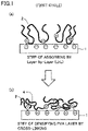
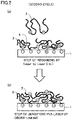
- the step of adsorbing the above ionic polyvinyl alcohol e.g., cationic PVA 2 alone ( FIG. 1 , FIG. 2 )
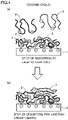
- a combination of cationic PVA 2 and anionic PVA 3 FIG. 3 , FIG. 4
- the cycle is carried out twice or more (see FIG. 2 , FIG. 4 ).
- only one cycle of adsorption and cross-linking may provide desalting properties, it is preferable to perform two or more cycles because a separation membrane having less defects can be prepared.
- Conditions of the first cross-linking with aldehyde may be different from the conditions of the second or later cross-linking with aldehyde, in view of optimization of properties of the membrane.
- the time of bringing the supporting membrane into contact with the cross-linking solution is preferably 10 minutes or more and 24 hours or less in view of sufficient reaction to increase the density of cross-linking.
- the temperature of cross-linking is preferably 10 to 80°C, and more preferably 20 to 50°C or less in view of sufficient increase of reactivity.
- the cross-linking solution include acid as a catalyst.
- Sulfuric acid, hydrochloric acid, acetic acid and citric acid may be used as acid, and it is preferable to use sulfuric acid because it is convenient and effective for cross-linking reaction.
- the above cross-linking caused by acetalization includes formation of an intermolecular cross-linked structure formed by dehydration condensation of two hydroxyl groups of adjacent structural units of vinyl alcohol and an aldehyde group in polyvinyl alcohol (copolymer) and also includes formation of a cross-linked structure in which polymer molecules are connected through a plurality of cyclic acetals with dialdehyde and trialdehyde.
- the composite membrane having the above separation layer has high desalting properties of an RO membrane. Furthermore, the firm bonding between the supporting membrane and the separation layer with Coulomb's force prevents reduction of properties caused by peeling of the separation layer and formation of pinholes even in operation such as backwash.
- the cross-linked ionic PVA separation layer in the composite membrane has a thickness of preferably 1 to 100 nm, and more preferably 5 nm or more and 50 nm or less.
- NMP N-methyl-2-pyrrolidone
- PPO 646 polyphenylene oxide manufactured by SABIC Innovative Plastics
- the stock solution for film formation was discharged as an external solution and an aqueous NMP solution containing 20% by mass of NMP was simultaneously discharged as an internal solution from the hollow part, to thereby form the stock solution into a hollow fiber.
- the fiber discharged was dried in air gap at room temperature, and then immersed in a coagulation bath filled with pure water at 25°C.
- the PPO hollow fiber membrane obtained was sufficiently washed to remove impurities such as remaining solvent, and was dried at room temperature.
- the PPO hollow fiber membrane of the supporting membrane A1 had an outer diameter of 250 ⁇ m, a film thickness of 50 ⁇ m, and a pure water permeance of 24 LMH/ bar.
- the hollow fiber membrane of the supporting membrane A2 had an outer diameter of 144 ⁇ m, a film thickness of 42 ⁇ m, and a pure water permeance of 0.5 LMH/bar.
- a module for evaluation was prepared using the bundle of hollow fiber membranes obtained and the test for pure water permeance and the test for salt water filtration were performed to measure the pure water permeance and the NaCl-rejection rate. Also, the strength at break of the hollow fiber membrane and the ratio of elemental sulfur (S) on the surface of the membrane were measured. The experimental results shown in Table 2 (Examples 1 to 5) were obtained.
- a PPO stock solution for film formation was prepared in the same manner as in preparation of supporting membrane A.
- a polyester paper manufactured by Hirose Paper Mfg Co., Ltd.
- the coated membrane on the metal substrate was immersed in a coagulation bath filled with pure water at 25°C to give a PPO flat membrane.
- the membrane was cleaned to remove impurities such as remaining solvent.
- the PPO flat membrane excluding the polyester paper had a thickness of 40 ⁇ m.
- the test for pure water permeance was performed and as a result the pure water permeance was 32 LMH/ bar.
- Supporting membrane B (PPO flat membrane) which had been dried was held in a polytetrafluoroethylene frame, and sulfuric acid having a concentration shown in Table 2 (Example 6) was poured onto the outer surface of the supporting membrane to sulfonate the outer surface of the membrane. After the treatment with sulfonic acid, the sulfonated PPO flat membrane was thoroughly washed with pure water at 10°C until the pH of the washing solution became neutral.
- a hollow fiber membrane was prepared in the same manner as preparing supporting membrane A except for changing the temperature of the aqueous NMP solution in the coagulation bath to 40°C.
- the PPO hollow fiber membrane had an outer diameter of 250 ⁇ m, a film thickness of 50 ⁇ m, and a pure water permeance of 90 LMH/ bar.
- a composite membrane was prepared by coating supporting membrane C with the SPPO polymer synthesized as described above by the following procedure.
- the hydrous supporting membrane C in the form of hollow fiber wound on a bobbin was unwound, transferred on a roller and immersed in a bath at 40°C filled with an aqueous glycerol solution having a concentration of 80% by mass to carry out a clogging treatment.
- the hollow fiber membrane clogged with glycerol was dipped in a bath filled with a 1 mass % SPPO solution in dimethyl sulfoxide, and the membrane was pulled up vertically and introduced into a convection dryer to be dried at 160°C for 1 minute.
- NMP was added to the SPPO polymer synthesized as described above to a concentration of 30% by mass and the mixture was kneaded to give a homogeneous stock solution for film formation.
- the stock solution was discharged from a double cylindrical nozzle and formed into hollow fiber using a 5% by mass aqueous ammonium nitrate solution as an internal solution.
- the fiber was dried in air gap and then coagulated in a coagulation bath filled with pure water to give a SPPO hollow fiber membrane.
- the SPPO hollow fiber membrane has an outer diameter of 250 ⁇ m and a film thickness of 50 ⁇ m.
- the 800 hollow fiber membranes which had been dried was formed into a 1-m long loop to prepare a module for evaluation.
- the pure water permeance and the NaCl-rejection rate were measured in the same manner as described above.
- the strength at break of the hollow fiber membrane and the ratio of elemental sulfur (S) on the surface of the membrane were measured in the same manner as described above.
- the experimental results shown in Table 2 (Comparative Example 2) were obtained.
- a separation layer made of an ionic PVA was formed by an LbL method on the outer surface of hollow supporting membranes A1 and A2 prepared as described above (see Table 2 for supporting membrane A1 prepared under different conditions of sulfonation and supporting membrane A2 prepared under different conditions for forming a film as the supporting membrane), on the outer surface of supporting membranes B, D and on the surface of flat supporting membrane C. Details of the ionic PVA (copolymers) used are described below.
- a reflux condenser, a stirrer, an inlet for introducing nitrogen, a thermometer and an inlet for introducing catalyst and monomer were attached to a 2-L round flask.
- a 2-L round flask 440 g of methanol, 500 g of vinyl acetate (VAC) and 4.8 g of a 60% aqueous solution of diallyldimethylammonium chloride (DADMAC) as a cationic monomer were placed, and while introducing nitrogen, the temperature was increased to 60°C.
- DMAC diallyldimethylammonium chloride
- V-65 2,2'-Azobis(2,4-dimethylvaleronitrile)
- the resulting cationic PVA had a degree of saponification of 99.7%.
- the PVA had a weight average molecular weight measured by GPC of 70,200.
- the amount of cationic monomers introduced measured by 1 H-NMR was 1.1% by mole.
- An anionic group-containing polyvinyl alcohol copolymer was prepared in the same manner as in the synthesis of the compound represented by the formula (3) except for using sodium allylsulfonate as the anionic monomer. NV at the time of completion of the reaction was 32%.
- the resulting APVA had a degree of saponification of 99.6%.
- the APVA had a weight average molecular weight measured by GPC of 36,000.
- the amount of cationic monomers introduced measured by 1 H-NMR was 1.4% by mole.
- a polyvinyl alcohol separation layer was formed by an LbL method as schematically described in FIG. 1 .
- CPVA cationic polyvinyl alcohol
- SPPO sulfonated PPO
- GA glutaraldehyde
- the cross-linking time with GA in the second cycle was 15 hours at 40°C. This provided a separation membrane whose number of PVA laminations was two.
- the appropriate number of fiber bundles of the hollow fiber supporting membranes (supporting membranes A1, A2, C and D) and the hollow fiber composite membranes (Examples 1 to 5 and Comparative Examples 1,2) were formed into a loop and this was inserted into a polycarbonate sleeve having an inner diameter of 13 mm and a length of 5 cm. Then two-pack epoxy resin was injected into the sleeve and cured to encapsulate the membranes. The end of the hollow fiber membrane after curing was cut to form an opening face of the hollow fiber membrane to prepare a module for evaluation.
- the module for evaluation was connected to a tester for properties of hollow fiber membrane equipped with a feed water tank and a pump to evaluate properties.
- FR L/m 2 / day Amount of water which might pass L / area of membrane m 2 / collecting time minutes ⁇ 60 minutes ⁇ 24 hours
- the pure water permeance (A value) was determined by the following equation after carrying out a permeation test with pure water to measure water permeation (FR).
- a value [LMH / bar] FR [L/ m 2 /day] / 24 [hours]/ testing pressure [bar] wherein LMH means L/ m 2 /h.
- the membrane was arranged upside down in SEPA-CFII Cross Flow Tester, and operation of backwash was performed so that pressure was applied to the separation layer from the supporting membrane. Pure water was fed at a pressure of 10 bar (1.0 MPa) to perform the operation of backwash for 30 minutes. Subsequently, the NaCl-rejection rate was evaluated in the same manner as for the hollow fiber membranes to evaluate retention of the rejection rate before and after the operation of backwash.
- the pressure for evaluation was increased by 0.5 bar at intervals of 20 minutes, and the collapse pressure at which the hollow fiber membrane was compressed and deformed irreversibly to significantly reduce water permeance was measured to evaluate the difference in pressure resistance of the membranes. Since pressure resistance is affected by the ratio of the outer diameter to the inner diameter of the hollow fiber membrane and the density of polymer in the membrane, the membranes was made such that the cross-sectional shapes thereof were the same in Examples 1, 3, 4 and Comparative Examples 1, 2, except for Example 2, in which pressure resistance was evaluated at 55 bar (5.5 MPa).
- the shape of the supporting membranes was evaluated and the cross-sectional area of the supporting membranes was calculated by the following method.
- a suitable number of bundles of hollow fiber membrane was packed in pores of a 2-mm thick SUS plate in which pores having a diameter of 3 mm were opened, and the bundle was cut with a razor blade to expose a cross-section.
- a microscope ECLIPSE LV100
- an image processing apparatus DIGITAL SIGHT DS-U2
- DS-Ri1 manufactured by Nikon Corporation
- the outer diameter and the inner diameter of the cross-section of the hollow fiber membrane were measured using the measurement function of an image analyzing software (NIS Element D3.00 SP6) to calculate the outer diameter, the inner diameter and the thickness of the hollow fiber membrane.
- a hydrous sample was frozen with liquid nitrogen, cut and air-dried, and Pt was sputtered on the cut surface.
- the shape was observed using scanning electron microscope S-4800 manufactured by Hitachi, Ltd. at an accelerated voltage of 5kV to measure the thickness of the membrane.
- the ratio of elemental sulfur was determined by analyzing the amount of elemental sulfur on the surface of the sulfonated membrane by X-ray photoelectron spectroscopy (XPS). The amount of elemental sulfur on the outer surface of the hollow fiber supporting membrane and the flat supporting membrane was directly measured, while the amount on the inner surface of the hollow fiber supporting membrane was measured after opening the membrane with a knife. The apparatus used and conditions of measurement are as described below.
- the hollow fiber composite membrane and the flat composite membrane were electronically stained and then embedded in epoxy resin.
- the sample embedded was cut into an ultrathin piece using a ultramicrotome, carbon was deposited thereon and the sample was observed by the TEM.
- a transmission electron microscope, JEM-2100 manufactured by JEOL Ltd. was used.
- the condition of observation the sample was observed at an accelerated voltage of 200 kV.
- Table 2 show the following; in the composite membranes of Examples 1 to 6, which are included in the present invention, the sulfonated supporting membrane has an asymmetric structure, bonding properties of the supporting membrane and the separation layer are excellent, and thus defects such as separation between the surface of the sulfonated PPO membrane and the PPO supporting membrane are not caused. As a result, the retention of the NaCl-rejection rate is excellent.
- the composite membrane of Comparative Example 2 which was composed of a supporting membrane made of SPPO and a PVA separation layer, has excellent bonding properties between the supporting membrane and the separation layer, but the strength at break was clearly reduced because the whole supporting membrane was made of SPPO.
- the cross-sectional image (TEM image) of the composite membrane shown in FIG. 5 provides an example of the surface of the sulfonated PPO supporting membrane 1.
- the image also provides an example of a PVA cross-linked layer (PVA separation layer 5) formed on the surface of the sulfonated PPO supporting membrane.
Landscapes
- Chemical & Material Sciences (AREA)
- Chemical Kinetics & Catalysis (AREA)
- Engineering & Computer Science (AREA)
- Manufacturing & Machinery (AREA)
- Water Supply & Treatment (AREA)
- Inorganic Chemistry (AREA)
- Health & Medical Sciences (AREA)
- Materials Engineering (AREA)
- Organic Chemistry (AREA)
- Polymers & Plastics (AREA)
- Nanotechnology (AREA)
- Medicinal Chemistry (AREA)
- Transplantation (AREA)
- Separation Using Semi-Permeable Membranes (AREA)
Abstract
Description
- The Present invention relates to a composite membrane and a method for producing a composite membrane.
- Reverse osmosis (RO) membranes and the like have a pore size of several angstroms, and thus has high resistance of filtration. Thus, a composite membrane is preferably used which includes an ultrafiltration membrane having excellent water permeability as a supporting membrane and a separation layer in a thin film state formed on the surface of the supporting membrane and thus has a reduced permeation resistance.
- As a composite membrane prepared by a coating method involving use of polyphenylene oxide having excellent chemical durability as a supporting membrane, Patent Literature 1 (
WO 2014/054346 ) discloses a composite separation membrane comprising a supporting membrane comprising polyphenylene oxide (polyphenylene ether) and a separation layer on the surface thereof, the separation layer comprising a sulfonated polyarylene ether copolymer having a repeated structure of a hydrophobic segment and a hydrophilic segment. - Furthermore, Patent Literature 2 (
WO 2017/064936 ) discloses a composite membrane comprising a composite separation membrane similar to that of Patent Literature 1 (on the surface of the sulfonated polyarylene ether copolymer) and a separation layer on the surface thereof, the separation layer prepared by adsorbing and crosslinking polyvinyl alcohol having an ionic functional group by a Layer-by-Layer method (e.g., G. Decher, Science, vol. 277, Issue 5330, pp. 1232-1237, 1997). Forming a separation layer made of polyvinyl alcohol (PVA) having an ionic functional group improves the properties of rejecting neutral low molecular weight substances. - In a separation membrane prepared by applying a Layer-by-Layer method (LbL method), a plurality of polymer layers carrying a positive or negative charge are alternately laminated on the surface of a supporting membrane (on the surface carrying a charge). The LbL method enables easy lamination of defect-free thin films and thus the amount of thin film materials such as polymer to be used can be very small. Accordingly, the method is economical and has little environmental load. In
Patent Literature 2, the LbL method is available because the sulfonated polyarylene ether copolymer is charged. -
- PTL 1:
WO 2014/054346 - PTL 2:
WO 2017/064936 - However, in
Patent Literature 2, it is necessary to prepare a composite membrane by laminating a separation layer made of a sulfonated polyarylene ether copolymer on the polyphenylene oxide (PPO) supporting membrane by a coating method or the like before forming a cross-linked PVA membrane by the LbL method. This has the problem of a complicated process of production and high production cost. Furthermore, since uneven thickness of coating is inevitable in the coating method inPatent Literature 2, the problem is that defects such as pinholes and cracks are easily generated in the separation layer when the separation layer is formed in the step of drying after coating. - Moreover, usually no strong bond such as a covalent bond or an ionic bond is present between the supporting membrane and the separation layer in a composite membrane prepared by the conventional interfacial polymerization method or coating method. For this reason, the problem of peeling of the separation layer is caused in treatment in which water pressure is applied from the side of the supporting membrane to the side of the separation layer as in backwash, though the integrity of membrane is not a problem in normal operation of filtration, i.e., when water pressure is applied from the side of the separation layer to the side of the supporting membrane.
- More specifically, in
Patent Literature 2, adhesiveness between the sulfonated polyarylene ether copolymer layer and the polyvinyl alcohol layer is excellent due to adhesion force of an ionic bond; however, since there is no chemical bond between the PPO supporting membrane and the sulfonated polyarylene ether copolymer layer, backwash easily causes peeling of the separation layer, and this results in the problem of reduction of the performance of the membrane. - In consideration of the above problems, an object of the present invention is to provide a composite membrane comprising a supporting membrane including polyphenylene oxide (PPO) and a separation layer including polyvinyl alcohol (PVA) having an ionic functional group, which can be produced by a simple method and has excellent bonding properties between the supporting membrane and the separation layer, and in which peeling of the separation layer and defects in the separation layer, such as pinholes, are not easily caused in backwash and the like.
-
- (1) A composite membrane comprising: a supporting membrane that includes polyphenylene oxide; and a separation layer that is disposed on one main surface of the supporting membrane, wherein the polyphenylene oxide is sulfonated on the one main surface of the supporting membrane and the separation layer includes polyvinyl alcohol having an ionic functional group.
- (2) The composite membrane according to (1), wherein the one main surface of the supporting membrane has a ratio of elemental sulfur of 0.2 to 10%.
- (3) The composite membrane according to (1) or (2), wherein the ionic functional group is a cationic functional group including a quaternary ammonium group.
- (4) The composite membrane according to any of (1) to (3), wherein the ionic functional group is an anionic functional group including a sulfonic acid group.
- (5) The composite membrane according to any of (1) to (4), wherein the polyvinyl alcohol is crosslinked in the separation layer.
- (6)A method for producing the composite membrane according to any of (1) to (5), comprising: bringing sulfuric acid into contact with a surface of the supporting membrane, thereby sulfonating at least part of the surface; and adsorbing the separation layer to the sulfonated surface of the supporting membrane.
- (7) The method according to (6), wherein concentrated sulfuric acid having a concentration of 90 to 98% by mass is brought into contact with the surface of the polyphenylene oxide composite membrane in the sulfonating.
- (8) A porous membrane comprising polyphenylene oxide, wherein polyphenylene oxide is sulfonated on one main surface of the porous membrane.
- The present invention provides a composite membrane comprising a supporting membrane comprising polyphenylene oxide (PPO) and a separation layer comprising polyvinyl alcohol (PVA) having an ionic functional group, which can be produced by a simple method and which has excellent bonding properties between the supporting membrane and the separation layer.
- In the present invention, the surface of the PPO supporting membrane may be sulfonated and a separation layer made of polyvinyl alcohol having an ionic functional group may be laminated on the sulfonated surface. Thus, it is not necessary to prepare a composite membrane composed of a PPO membrane and a separation layer made of sulfonated polyarylene ether copolymer, and therefore a composite membrane comprising a supporting membrane comprising PPO and a separation layer comprising PVA can be produced by a simple method.
- Furthermore, in the present invention, the supporting membrane has an asymmetric membrane structure in which a PPO phase is gradually replaced by a sulfonated PPO phase, and thus the membrane does not have a bonding interface of different polymers as in the composite membrane of a PPO membrane and a sulfonated polyarylene ether copolymer disclosed in
Patent Literature 2. Thus, defects such as peeling of the separation layer in, for example, backwash, are unlikely to occur. - Moreover, the PVA separation layer is bonded to the sulfonated surface of the PPO supporting membrane (sulfonated PPO) via an ionic bond. Thus, the supporting membrane and the separation layer are firmly bonded also in the composite membrane finally prepared, and thus defects such as peeling of the separation layer in, for example, backwash, are unlikely to occur.
-
-
FIG. 1 is a schematic view illustrating the process for forming a separation layer on the main surface of a supporting membrane for the composite membrane of the present invention. -
FIG. 2 is a schematic view illustrating the process for forming a separation layer on the main surface of a supporting membrane for the composite membrane of the present invention. -
FIG. 3 is a schematic view illustrating the process for forming a separation layer on the main surface of a supporting membrane for the composite membrane of the present invention. -
FIG. 4 is a schematic view illustrating the process for forming a separation layer on the main surface of a supporting membrane for the composite membrane of the present invention. -
FIG. 5 is a photograph showing a cross-sectional view of the composite membrane of the present invention. - The composite membrane of the present invention comprises a supporting membrane that includes polyphenylene oxide and a separation layer that is disposed on one main surface of the supporting membrane.
- Polyphenylene oxide is sulfonated on one main surface (the main surface on which the separation layer is disposed) of the supporting membrane.
- The separation layer includes polyvinyl alcohol having an ionic functional group.
- The composite membrane of the present invention comprises a separation layer made of polyvinyl alcohol having an ionic functional group (e.g., a cross-linked PVA thin film) on the main surface of a supporting membrane comprising polyphenylene oxide (e.g., a supporting membrane comprising an anionic sulfonated polyphenylene oxide). Thus, the membrane has high separability for monovalent or polyvalent ions, neutral substances and the like, and thus may be preferably used as, for example, a liquid treatment membrane and gas separation membrane. In particular, the composite membrane may be preferably used as a reverse osmosis membrane.
- The supporting membrane comprises polyphenylene oxide (PPO). It is preferable that the supporting membrane be a porous membrane.
- The supporting membrane may be made of PPO alone or may include a material other than PPO. It is preferable that PPO be present on at least one main surface of the supporting membrane. Polyphenylene oxide is an engineering plastic which has excellent chemical durability for alkali and free chlorine, excellent water resistance, and excellent mechanical strength, and fabricability suitable for forming a film from a solution.
- The present inventors have found that the surface of the supporting membrane comprising PPO can be easily and efficiently sulfonated by bringing concentrated sulfuric acid into contact with the surface without reducing mechanical strength of the supporting membrane.
- Typical examples of polyphenylene oxide (PPO) include poly(2,6-dimethyl-1,4-phenylene oxide) having the structure represented by the following formula (1). In the formula, n represents a natural number.


- Examples of commercially available engineering plastics include polyethersulfone, polysulfone, polyphenylsulfone, polyvinylidene fluoride, polyether ether ketone, polyphenylene oxide (PPO) and polyphenylene sulfide. Only polyphenylene oxide can be easily sulfonated using sulfuric acid without reduction in the molecular weight and is insoluble in sulfuric acid.
- Polyarylsulfone polymers such as polyethersulfone, polysulfone and polyphenylsulfone, for example, are dissolved in sulfuric acid or swell significantly. In addition, these polymers are difficult to sulfonate on adjacent benzene rings because of electron withdrawing properties of the sulfonyl group in the main chain. For these reasons, sulfonation of a supporting membrane with sulfuric acid is difficult.
- Since polyvinylidene fluoride does not have a benzene ring in the chemical structure, sulfonating polyvinylidene fluoride with sulfuric acid is difficult. Although such polymers can be sulfonated under harsh conditions such as high temperature concentrated sulfuric acid, chlorosulfuric acid or fuming sulfuric acid, they are not preferable because they are likely to cause damage to the structure of the supporting membrane or not preferable from economical or working viewpoint. Polyether ether ketone is easily sulfonated with sulfuric acid, but is dissolved in sulfuric acid. Polyphenylene sulfide is insoluble in almost all solvents, making the formation of a film from a solution itself difficult.
- It is preferable that polyphenylene oxide used for the supporting membrane have a number average molecular weight of 5,000 or more and 500,000 or less. In that range, polyphenylene oxide is soluble in nonprotic solvent such as N-methyl-2-pyrrolidone (NMP), N,N-dimethylacetamide (DMAc) and N,N-dimethylformamide (DMF) at high temperature, and thus a supporting membrane having sufficient strength can be prepared by a wet phase separation method or a dry wet phase separation method.
- The above supporting membrane may include various types of known additives to optimize membrane properties. Examples of additives include a polymer (e.g., polystyrene), a filler, a surfactant and a hydrophilizing agent (e.g., polyethylene glycol and polyvinyl pyrrolidone).
- For the solvent which dissolves polyphenylene oxide,
WO 2014/054346 can be referred to, for example. Examples of solvents include nonprotic polar solvents such as N-methyl-2-pyrrolidone (NMP), N,N-dimethylacetamide (DMAc) and N,N-dimethylformamide (DMF). These solvents can dissolve PPO at a temperature of about 80°C or more and has relatively low environmental load, and thus these solvents can be preferably used. Of them, NMP is more preferred. - A wet phase separation method or a dry wet phase separation method may be preferably used as the method for forming a film to prepare the supporting membrane. The wet film forming method is a method for forming a membrane structure, in which a stock solution for film formation is immersed in a coagulation bath of a non-solvent which is mixed with a good solvent in the stock solution but in which polymer is insoluble to precipitate polymer by phase separation. The dry wet film forming method is a method in which solvent is evaporated and dried for a certain time from the surface of a stock solution for film formation immediately before immersing the stock solution in a coagulation bath to give an asymmetric structure in which the density of polymer on the surface of the membrane is high. In the present invention, it is more preferable to select the dry wet film forming method.
- The form of the supporting membrane (and the composite membrane) according to the present invention is not particularly limited, and a flat membrane and a hollow fiber membrane are preferred. These membranes can be prepared by a method known to a person skilled in the art. For example, a flat membrane may be produced by casting a stock solution on a substrate, optionally drying for a predetermined period, and then immersing the resultant in a coagulation bath. A hollow fiber membrane may be produced by discharging a stock solution through the outer slit of a double cylindrical spinning nozzle in the form of a hollow cylinder while extruding a fluid through the inner slit together with the stock solution, optionally drying for a predetermined period, and then immersing the resultant in a coagulation bath, wherein examples of the fluid include a non-solvent, an implicit solvent, a good solvent or a mixed solvent thereof, or liquid which is not compatible with the film forming solvent, or gas such as nitrogen or air.
- The concentration of polyphenylene oxide in the stock solution for film formation is preferably 5% by mass or more and 60% by mass or less, and more preferably 10% by mass or more and 50% by mass or less in view of provision of sufficient mechanical strength of the supporting membrane and optimization of water permeability and surface pore diameters of the supporting membrane (porous supporting membrane).
- The temperature of the stock solution for film formation is preferably 40°C or more and more preferably 60°C or more. For the upper limit, the temperature is preferably the boiling point or less of the above non-polar protonic solvent, more preferably 150°C or less, and further preferably less than 100°C. When the temperature of the stock solution is less than the above range, polyphenylene oxide may precipitate due to thermally induced phase separation. By contrast, when the temperature of the stock solution is far beyond the above range, the viscosity of the stock solution is reduced, making fabrication difficult. Furthermore, since too high a temperature of the stock solution brings about an increased rate of evaporation of the good solvent in the stock solution and an increased rate of solvent exchange in the coagulation bath, the density of polymer on the surface of the membrane may be extremely increased, and thus water permeability of the supporting membrane may be significantly reduced.
- There is a predetermined period of drying solvent in the dry wet film forming method before the step of immersing the stock solution in a coagulation bath. The time and the temperature of drying are not particularly limited, and are to be adjusted so that the asymmetric structure of the supporting membrane finally prepared is as desired. It is preferable that part of the solvent be dried in an atmosphere at a temperature of 5 to 200°C for 0.01 to 600 seconds.
- The non-solvent in the coagulation bath used for the wet film forming method or the dry wet film forming method is not particularly limited, and is preferably water, alcohol, polyhydric alcohol (such as ethylene glycol, diethylene glycol, triethylene glycol, glycerol), and may be a mixture liquid thereof, as in known film forming methods. It is preferable that the main component be water from convenient and economical viewpoint.
- Furthermore, it is preferable to add a film forming solvent (e.g., NMP, DMAc) to the non-solvent in the coagulation bath in view of control of the rate of solvent exchange in the coagulation process and provision of a preferable membrane structure. Polysaccharide and water-soluble polymers may be added to the coagulation bath in view of control of the viscosity of the coagulation bath.
- The temperature of the coagulation bath is appropriately selected in view of control of the pore size of the supporting membrane (porous supporting membrane), economic efficiency and operational safety. More specifically, the temperature is preferably 5°C or more and less than 100°C, more preferably 10°C or more and 80°C or less. When the temperature is lower than the range, the viscosity of the coagulation solution is increased, thereby resulting in slow progress of the process of demixing, and as a result the structure of the membrane becomes dense, so that water permeability of the membrane is likely to be reduced. When the temperature is higher than the range, the process of demixing progresses instantly, and as a result the membrane structure becomes coarse, so that the strength of the membrane is likely to be reduced.
- The time of immersion in the coagulation bath may be adjusted to a time in which the structure of the supporting membrane is sufficiently formed by phase separation. The time is preferably in the range of 0.1 to 1,000 seconds, more preferably 1 to 600 seconds in view of sufficient progress of coagulation and avoiding processes from getting long.
- It is preferable that the supporting membrane obtained after completing formation of a membrane structure in the coagulation bath be washed with water. The method of washing with water is not particularly limited, and the membrane may be immersed in water for a sufficient time, or may be washed with running water for a predetermined time while being transferred between rolls.
- The supporting membrane after water washing may be stored in a hydrous state or a dry state.
- In the above supporting membrane, PPO is sulfonated on one main surface. It is preferable that the sulfonated main surface have an anionic charge derived from a sulfonic acid group.
- A method for sulfonation in which a sulfonating agent is brought into contact with the surface of a supporting membrane is particularly preferably used as a method for sulfonation. The method is preferred because of the following: when a solution in which the concentration of the sulfonating agent has been suitably controlled is brought into contact with a membrane, only the surface of the membrane and fine pores on the surface are sulfonated, whereas polymer components in bulk (in the inside) are not sulfonated, and thus the surface of the membrane can be sulfonated to a high degree without reducing mechanical strength of the whole membrane.
- The sulfonated membrane thus formed is an asymmetric membrane having an inclined structure in which a bulk neat polymer phase is gradually replaced by a sulfonated polymer phase, and thus the membrane has a great advantage in that peeling of the separation layer is not caused even in operation in which water pressure is applied from the side of the supporting membrane to the side of the separation layer as in backwash.
- In the supporting membrane, PPO may be sulfonated on at least one main surface (the main surface on which the separation layer is disposed). When the method for sulfonation described above is used, the surface portion (including the surface of fine pores) is usually sulfonated in addition to the surface of the supporting membrane.
- By sulfonation, polyphenylene oxide is formed into a copolymer including a structural unit into which a sulfonic acid group has been introduced, which is shown on the right of the following formula (2). In the formula (2), n and m each independently represent a natural number.

- In the present invention, the method for sulfonation does not include a method for preparing a composite membrane by applying a polymer which has been previously sulfonated to a supporting membrane. The reason is that in a composite membrane prepared by such a method, peeling of the separation layer is likely to occur in operation such as backwash as described above.
- Furthermore, in the method for preparing a supporting membrane by using a polymer which has been previously sulfonated (PPO) or a polymer stock solution including a sulfonated polymer as a stock solution, not only the surface of the membrane but also the bulk phase (the inside) are sulfonated. However, a supporting membrane made of polymer having high sulfonation degree all over the whole membrane has the problem of reduction of mechanical strength. Thus, a method by which the polymer inside of the membrane is not sulfonated is preferred, though the surface of the supporting membrane needs to be sufficiently sulfonated to effectively carry out the step for adsorbing ionic polyvinyl alcohol by the Layer-by-Layer method described later.
- It is preferable to use sulfuric acid as a sulfonating agent because it is convenient and inexpensive. Since polyphenylene oxide is susceptible to electrophilic substitution reaction on the benzene ring in the main chain thereof and does not include an electron withdrawing functional group such as sulfonic group in the main chain, polyphenylene oxide can be easily sulfonated.
- The concentration of sulfuric acid is preferably 90% or more and 98% or less, more preferably 92% or more and 96% or less. The present inventors have found that the supporting membrane can be sulfonated with sulfuric acid having a relatively low concentration of about 92 to 96%.
- The time of contact with sulfuric acid depends on the concentration of sulfuric acid and the reaction temperature, and is preferably 10 seconds to 6 hours, and more preferably 30 seconds to 2 hours.
- When the concentration of sulfuric acid is lower than the range or when the reaction time is shorter than the range, the supporting membrane may not be sufficiently sulfonated, and adsorption of ionic polyvinyl alcohol at the later stage may not proceed effectively to fail to obtain sufficient separability. When the concentration of sulfuric acid is higher than the range or when the reaction time is longer than the range, the supporting membrane may be excessively sulfonated, and as a result the surface of the membrane may be swelled to increase the size of fine pores, so that sufficient separability may not be obtained.
- A sulfonating agent having higher reactivity, such as chlorosulfuric acid, fuming sulfuric acid and sulfur trioxide may also be used as another sulfonating agent. It is preferable to use sulfuric acid in view of the cost, environmental load and control of the sulfonation degree.
- The sulfonation degree of the surface of the membrane are not particularly limited, and those which optimize properties of the composite membrane after the Layer-by-Layer treatment at the later stage and mechanical strength of the supporting membrane are selected.
- Evaluation of the NaCl-rejection rate of the supporting membrane after sulfonation is preferably used to evaluate the sulfonation degree. In the evaluation of the NaCl-rejection rate under conditions of evaluation of 0.5 MPa and a concentration of NaCl of 1500 ppm, the rejection rate is preferably in the range of 5 to 70% and more preferably 10 to 60%.
- For the evaluation of the sulfonation degree, measurement of elemental composition by X-ray photoelectron spectroscopy (XPS) may also be preferably used, in which the amount of elemental sulfur derived from a sulfonic acid group on the surface of the supporting membrane is relatively compared. Although the ratio of elemental sulfur by XPS may slightly vary depending on the ratio of the amount of elements derived from the remaining solvent, the ratio of elemental sulfur on one main surface (the main surface on which the separation layer is disposed) of the supporting membrane is preferably 0.2 to 10%, and more preferably 0.5 to 5%. It is preferable that the ratio of elemental sulfur on the other main surface of the supporting membrane be less than 0.5%.
- In the case of a flat membrane and a hollow fiber membrane of an outside-in filtration mode, a batch treatment involving immersing a supporting membrane in a bath filled with sulfuric acid or a continuous immersion treatment by transfer between rolls may be preferably used as a method for immersing the supporting membrane in sulfuric acid.
- It is preferable to wash with pure water the supporting membrane after treatment with sulfuric acid. It is preferable to extend the time of washing with pure water or carry out a multi-stage washing step so that no sulfur remains. It is also preferable to immerse the membrane in an aqueous solution of an inorganic salt such as sodium sulfate, sodium chloride or potassium chloride after washing as necessary to replace proton as the counter ion in the sulfonic acid group with an inorganic ion in view of improvement in thermal stability of polymer.
- In the case of a hollow fiber membrane of an inside-out filtration mode, it is preferable to use a method in which hollow fiber membranes are formed into a module in advance, the potting portions at both ends of a bundle of hollow fiber membranes is cut and opened, and sulfuric acid is injected thereinto from the end to sulfonate the inner surface of the hollow fiber membrane.
- When immersed in sulfuric acid, the supporting membrane may be either dried or hydrous. It is preferable that when a hydrous membrane is immersed in sulfuric acid, the membrane be once immersed in sulfuric acid having low concentration (e.g., 80 to 90% by mass) and then subjected to treatment using sulfuric acid having high concentration (e.g., 90% by mass or more), in view of reduction of heat generation caused by mixing of sulfuric acid and water and change in the concentration of the sulfuric acid bath. When a dried supporting membrane is used, it is preferable to carry out a treatment using sulfuric acid having high concentration (e.g., 90% by mass or more) directly.
- A separation layer is disposed on one main surface of the supporting membrane. The separation layer includes polyvinyl alcohol having an ionic functional group.
- The sulfonated main surface of the supporting membrane (sulfonated PPO) is strongly anionic. This enables a thin separation layer (e.g., 1 nm to 100 nm) to be formed by an LbL method in which polyvinyl alcohol having an ionic functional group is brought into contact therewith.
- Polyvinyl alcohol having an ionic functional group (ionic PVA) is used for forming the separation layer.
- The ionic functional group is at least a cationic functional group (cationic group) or an anionic functional group (anionic group). Since the sulfonated surface of the supporting membrane is anionic as described above, PVA having at least a cationic group is used to prepare a separation membrane by an LbL method.
- Polyvinyl alcohol having a cationic group (cationic PVA) may be provided by a known polymerization method. A solution polymerization method using methanol is convenient and thus preferably used. A method may be used which includes copolymerizing vinyl acetate and a cationic group-containing monomer and then saponifying the resultant with alkali to give the intended cationized polyvinyl alcohol, or a method may be used in which part of the hydroxyl groups of polyvinyl alcohol which has been previously saponified is reacted with a cationizing agent having an epoxy group to give a cationized copolymer.
- Examples of cationic groups include an amino group, an imino group, an ammonium group, a sulfonium group and a phosphonium group. A quaternary ammonium group is preferred because it is easily available and has excellent durability for free chlorine. Furthermore, it is preferable that the cationic group-containing monomer unit should not include an ester bond, in view of provision of durability to hydrolysis by alkali. Polyvinyl alcohol (copolymer) may include two or more types of cationic group-containing monomers.
- The counter ion of the cationic group is not particularly limited, and chloride ions are convenient and preferred.
- It is preferable that the cationic PVA copolymer have a weight average molecular weight (Mw) of 10,000 or more and 200,000 or less in a differential molecular weight distribution curve obtained in gel permeation chromatography.
- A specific preferred example of the cationic PVA is a polyvinyl alcohol copolymer containing a cyclopolymerization product of diallyl dimethylammonium chloride represented by the following formula (3) because it has excellent resistance to free chlorine and alkali resistance. In the formula (3), m, n and l each independently represent a natural number (the same applies to the following formulas (4) to (8)).

- Another preferred example of the cationic PVA is a polyvinyl alcohol copolymer containing a polymerization product of 3-(methacrylamido)propyl trimethylammonium chloride represented by the following formula (4) because it has excellent alkali resistance despite its poor resistance to free chlorine due to its amide bond.

- Still another preferred example of the cationic PVA is polyvinyl alcohol copolymer prepared by reacting glycidyl trimethylammonium chloride represented by the following formula (5) with part of the hydroxyl groups of polyvinyl alcohol because it has excellent resistance to free chlorine and alkali resistance.

- Polyvinyl alcohol having an anionic group (anionic PVA) may also be prepared by a known polymerization method. A solution polymerization method using methanol is convenient and thus preferably used. It is convenient and preferable to use, for example, a method including copolymerizing vinyl acetate and an anionic group-containing monomer and then saponifying the copolymer with alkali to give the intended anionic polyvinyl alcohol (copolymer).
- Examples of anionic groups include a sulfonic acid group, a carboxyl group and a phosphorus group. The sulfonic acid group is particularly preferred in view of availability and excellent ion dissociation properties. It is preferable that the anionic group-containing monomer unit should not include an ester bond, in view of provision of durability to hydrolysis by alkali. Polyvinyl alcohol (copolymer) may include two or more types of anionic group-containing monomers.
- The counter ion of the anionic group is not particularly limited, and sodium ions and potassium ions are convenient and preferred.
- A specific preferred example of the anionic PVA is a polyvinyl alcohol copolymer containing a polymerization product of sodium vinylsulfonate represented by the following formula (6) because it has excellent resistance to free chlorine and alkali resistance.

- Another preferred example of the anionic PVA is a polyvinyl alcohol copolymer containing a polymerization product of sodium allylsulfonate represented by the following formula (7) because it has excellent resistance to free chlorine and alkali resistance.

- Still another preferred example of the anionic PVA is a polyvinyl alcohol copolymer containing a polymerization product of sodium 2-acrylamide-2-methylpropanesulfonate represented by the following formula (8) because it has excellent alkali resistance despite its poor resistance to free chlorine due to its amide bond.

- It is preferable that when the above ionic PVA is a PVA copolymer including a structural unit containing a cationic group, the ratio of introduction of the structural unit containing an ionic functional group (in particular, a cationic group) be 0.3 to 6%. The ratio of introduction of a structural unit containing an ionic functional group, M (%), is represented by the following equation using symbols m, n, l in the above formulas.

- The amount of introduction of the ionic functional group can be measured by proton nuclear magnetic resonance (1H-NMR) using, for example, a deuterated solvent.
- When the ratio of introduction of a structural unit containing an ionic functional group, M, is less than the above range, the number of ionic bonds between the sulfonated surface of the supported membrane and the polyvinyl alcohol copolymer is very small to thereby fail to sufficiently form the adsorption layer, and as a result, desalting properties of the composite membrane finally obtained may not be sufficient. Furthermore, when the ratio of introduction of a structural unit containing an ionic functional group, M, is more than the above range, the charge density in the separation layer is excessively increased to thereby increase the pore size, and as a result desalting properties of the composite membrane finally obtained may not be sufficient.
- It is preferable that the above ionic polyvinyl alcohol have a degree of acetylation of less than 20%. In other words, it is preferable that the above ionic polyvinyl alcohol have a degree of saponification of 80% or more and less than 100%. When the degree of acetylation is more than the range, the density of crosslinking caused by aldehyde described later is reduced, and desalting properties of the composite membrane are likely to be reduced. It is preferable that the number of the acetyl groups in the structural unit of vinyl acetate, which is represented by symbol l in the above formula, be small, because of its susceptibility to alkaline hydrolysis. The degree of acetylation is preferably less than 5%, and more preferably less than 1%. The degree of acetylation A (%) is represented by the following equation using symbols n, l in the above formulas.

- The degree of acetylation (or degree of saponification) can be determined by proton nuclear magnetic resonance (1H-NMR) using, for example, a deuterated solvent.
- The molecular weight of ionic polyvinyl alcohol affects the ratio of desalting of the composite membrane. When the polyvinyl alcohol copolymer has a degree of acetylation within the range defined above and a molecular weight within the range of 10,000 or more and 200,000 or less, the composite membrane has preferable properties, though the molecular weight of the polyvinyl alcohol copolymer and properties of the membrane also vary depending on the degree of acetylation. When the molecular weight is less than the range, adsorbing molecules have extremely small coil diameter, and polymer enters the inside of the membrane from the surface of the supporting membrane, so that fine defects are likely to be formed in the separation layer. Furthermore, when the molecular weight is more than the range, adsorbing molecules have extremely large coil diameter, and fine defects are also likely to be formed in the separation layer. The polyvinyl alcohol copolymer has a molecular weight of more preferably 20,000 or more and 180,000 or less.
- The weight average molecular weight (molecular weight) of the ionic polyvinyl alcohol is measured by gel permeation chromatography (GPC) using hexafluoroisopropanol to which 10mM sodium trifluoroacetate has been added as a solvent, and is calculated in terms of polymethyl methacrylate as a standard substance.
- The surface of the sulfonated PPO supporting membrane is anionic, and thus when the above polyvinyl alcohol having an ionic functional group (e.g., an aqueous solution thereof) is brought into contact therewith, an adsorption layer may be formed via Coulomb's force using the known Layer-by-Layer (LbL) method.
- It is preferable to bring an aqueous solution of a polyvinyl alcohol copolymer having an anionic functional group into contact with the surface of the supporting membrane if desired. By repeating a cycle of bringing such an aqueous solution of a polyvinyl alcohol copolymer having a positive or negative ionic group into contact with the supporting membrane alternately and adsorbing it thereto several times, the amount of adsorption of polymer can be adjusted. It is preferable that at that stage a step of rinsing the surface of the supporting membrane with pure water for about 1 second to 30 minutes be inserted therebetween. The time of bringing the supporting membrane into contact with the respective polymer solutions is preferably 1 minute or more and 6 hours or less, and more preferably 10 minutes or more and 1 hour or less. The temperature of the polymer solution is preferably 5°C or more and less than 40°C, and more preferably 10°C or more ad 30°C or less. A highly integral and defect (e.g., a defect having a size of 1 nm or more and 100 nm or less)-free composite membrane may be gained under these conditions.
- It is preferable that the polyvinyl alcohol be crosslinked in the separation layer.
- By cross-linking hydroxyl groups of PVA with a cross-linking agent such as glutaraldehyde (acetalization), the PVA separation layer is made less hydrophilic and denser. A composite membrane having excellent permeation selectivity and high desalting ratio can be prepared by a cross-linking treatment of the PVA separation layer which has been formed to be extremely thin without defects by a LbL method.
- It is preferable to use aldehyde as a cross-linking agent because it is convenient and economical. Examples of aldehydes (aldehyde compounds) include formaldehyde, acetoaldehyde, propionaldehyde, glyoxal, malondialdehyde, succinaldehyde, glutaraldehyde, benzaldehyde, orthophthalaldehyde, isophthalaldehyde, terephthalaldehyde and 1,3,5-benzenetricarboaldehyde. Of them, formaldehyde and glutaraldehyde are preferably used in view of excellent reactivity of the cross-linking agent and excellent resistance to hydrolysis with acid of the cross-linked product. It is particularly preferable to use glutaraldehyde.
- It is preferable that the above cross-linking agent in the form of a solution (a crosslinking solution) be brought into contact with the surface of the supporting membrane. The solvent is not particularly limited, and it is preferable to select a solvent which can dissolve 0.1% by mass or more, more preferably 1% by mass or more, of aldehyde. Water, methanol, ethanol, isopropyl alcohol and a mixed solvent thereof, for example, are preferred as the solvent. It is preferable that the solvent contain 50% by mass or more of water as the main component in order to allow adsorption of polymer to proceed effectively by electrostatic force.
- For example, the step of adsorbing the above ionic polyvinyl alcohol (e.g.,
cationic PVA 2 alone (FIG. 1 ,FIG. 2 )) or a combination ofcationic PVA 2 and anionic PVA 3 (FIG. 3 ,FIG. 4 ) to the surface of the supportingmembrane 1 and cross-linking with aldehyde (formation of cross-linked portion 4) is regarded as a cycle (seeFIG. 1 ,FIG. 3 ), and it is preferable that the cycle be carried out twice or more (seeFIG. 2 ,FIG. 4 ). Although only one cycle of adsorption and cross-linking may provide desalting properties, it is preferable to perform two or more cycles because a separation membrane having less defects can be prepared. Conditions of the first cross-linking with aldehyde (the type of aldehyde, the concentration of the cross-linking solution, the temperature of cross-linking and the time of cross-linking) may be different from the conditions of the second or later cross-linking with aldehyde, in view of optimization of properties of the membrane. - The time of bringing the supporting membrane into contact with the cross-linking solution is preferably 10 minutes or more and 24 hours or less in view of sufficient reaction to increase the density of cross-linking.
- The temperature of cross-linking is preferably 10 to 80°C, and more preferably 20 to 50°C or less in view of sufficient increase of reactivity.
- It is preferable that the cross-linking solution include acid as a catalyst. Sulfuric acid, hydrochloric acid, acetic acid and citric acid may be used as acid, and it is preferable to use sulfuric acid because it is convenient and effective for cross-linking reaction.
- The above cross-linking caused by acetalization includes formation of an intermolecular cross-linked structure formed by dehydration condensation of two hydroxyl groups of adjacent structural units of vinyl alcohol and an aldehyde group in polyvinyl alcohol (copolymer) and also includes formation of a cross-linked structure in which polymer molecules are connected through a plurality of cyclic acetals with dialdehyde and trialdehyde.
- The composite membrane having the above separation layer has high desalting properties of an RO membrane. Furthermore, the firm bonding between the supporting membrane and the separation layer with Coulomb's force prevents reduction of properties caused by peeling of the separation layer and formation of pinholes even in operation such as backwash.
- The cross-linked ionic PVA separation layer in the composite membrane has a thickness of preferably 1 to 100 nm, and more preferably 5 nm or more and 50 nm or less.
- N-methyl-2-pyrrolidone (hereinafter abbreviated as NMP) was added to polyphenylene oxide PPO 646 (hereinafter PPO) manufactured by SABIC Innovative Plastics to a concentration of 30% by mass for A1 or 35% by mass for A2, and with kneading, PPO was dissolved therein at 130°C to give a homogeneous stock solution for film formation.
- Next, using a double cylindrical nozzle, the stock solution for film formation was discharged as an external solution and an aqueous NMP solution containing 20% by mass of NMP was simultaneously discharged as an internal solution from the hollow part, to thereby form the stock solution into a hollow fiber. The fiber discharged was dried in air gap at room temperature, and then immersed in a coagulation bath filled with pure water at 25°C. The PPO hollow fiber membrane obtained was sufficiently washed to remove impurities such as remaining solvent, and was dried at room temperature. The PPO hollow fiber membrane of the supporting membrane A1 had an outer diameter of 250 µm, a film thickness of 50 µm, and a pure water permeance of 24 LMH/ bar. The hollow fiber membrane of the supporting membrane A2 had an outer diameter of 144 µm, a film thickness of 42 µm, and a pure water permeance of 0.5 LMH/bar.
- 800 pieces of the supporting membranes A1 and A2 (PPO hollow fiber membrane) which were dried were formed into a 1-m long loop. The openings at both ends were sealed and the pieces were bundled. Subsequently, the fiber bundle was immersed in a polytetrafluoroethylene container filled with sulfuric acid adjusted to a concentration shown in Table 2 (Examples 1 to 5) for the time shown in Table 2 (Examples 1 to 4) to sulfonate the outer surface of the hollow fiber membrane. After treatment with sulfuric acid, the bundle of sulfonated PPO hollow fiber membranes was immersed in a pure water bath at 10°C, and the membrane was thoroughly washed with water until the pH of the washing solution became neutral.
- A module for evaluation was prepared using the bundle of hollow fiber membranes obtained and the test for pure water permeance and the test for salt water filtration were performed to measure the pure water permeance and the NaCl-rejection rate. Also, the strength at break of the hollow fiber membrane and the ratio of elemental sulfur (S) on the surface of the membrane were measured. The experimental results shown in Table 2 (Examples 1 to 5) were obtained.
- Details of the test for pure waterpermeance, the test for salt water filtration, the measurement of strength at break, the measurement of the ratio of elemental sulfur (S) on the surface of the membrane and the evaluation of shapes are as described later.
- A PPO stock solution for film formation was prepared in the same manner as in preparation of supporting membrane A. A polyester paper (manufactured by Hirose Paper Mfg Co., Ltd.) was fixed on a metal substrate placed on a hot plate, and the stock solution kept at 80°C was applied thereto by a hand coater. The coated membrane on the metal substrate was immersed in a coagulation bath filled with pure water at 25°C to give a PPO flat membrane. Then the membrane was cleaned to remove impurities such as remaining solvent. The PPO flat membrane excluding the polyester paper had a thickness of 40 µm. The test for pure water permeance was performed and as a result the pure water permeance was 32 LMH/ bar.
- Supporting membrane B (PPO flat membrane) which had been dried was held in a polytetrafluoroethylene frame, and sulfuric acid having a concentration shown in Table 2 (Example 6) was poured onto the outer surface of the supporting membrane to sulfonate the outer surface of the membrane. After the treatment with sulfonic acid, the sulfonated PPO flat membrane was thoroughly washed with pure water at 10°C until the pH of the washing solution became neutral.
- The pure water permeance and the NaCl-rejection rate of the flat membrane obtained were measured and the ratio of elemental sulfur (S) was measured in the same manner as described above. The experimental results shown in Table 2 (Example 6) were obtained.
- A hollow fiber membrane was prepared in the same manner as preparing supporting membrane A except for changing the temperature of the aqueous NMP solution in the coagulation bath to 40°C. The PPO hollow fiber membrane had an outer diameter of 250 µm, a film thickness of 50 µm, and a pure water permeance of 90 LMH/ bar.
- In a 5-L flask, 100 g of PPO was dissolved in 3,200 g of chloroform and a chloroform solution containing 80 g of chlorosulfuric acid was added dropwise thereto at room temperature to allow a sulfonation reaction to proceed for 2 hours to give a reaction product. Subsequently, the reaction product was re-precipitated in hexane and filtrated. A cake-like product obtained by filtration was crashed and immersed in an aqueous 1 M sodium carbonate solution to neutralize the sulfonic acid group in the reaction product with sodium ions. Then, the polymer was formed into flakes and the flakes were thoroughly washed with ion exchange water to remove sodium carbonate salt completely. Thereafter the polymer was dried to give the intended sulfonated PPO (SPPO) polymer. The sulfonation degree measured by 1H-NMR was 20% by mole.
- A composite membrane was prepared by coating supporting membrane C with the SPPO polymer synthesized as described above by the following procedure. The hydrous supporting membrane C in the form of hollow fiber wound on a bobbin was unwound, transferred on a roller and immersed in a bath at 40°C filled with an aqueous glycerol solution having a concentration of 80% by mass to carry out a clogging treatment. Subsequently, the hollow fiber membrane clogged with glycerol was dipped in a bath filled with a 1 mass % SPPO solution in dimethyl sulfoxide, and the membrane was pulled up vertically and introduced into a convection dryer to be dried at 160°C for 1 minute.
- 800 hollow fiber membranes which had been dried was formed into a 1-m long loop to prepare a module for evaluation. The module for evaluation was immersed in ethanol for 30 minutes and then ethanol was completely replaced with pure water. Thereafter the pure water permeance and NaCl-rejection rate were measured in the same manner as described above. Furthermore, the strength at break of the hollow fiber membrane and the ratio of elemental sulfur (S) on the surface of the membrane were measured in the same manner as described above. The experimental results shown in Table 2 (Comparative Example 1) were obtained.
- NMP was added to the SPPO polymer synthesized as described above to a concentration of 30% by mass and the mixture was kneaded to give a homogeneous stock solution for film formation. The stock solution was discharged from a double cylindrical nozzle and formed into hollow fiber using a 5% by mass aqueous ammonium nitrate solution as an internal solution. The fiber was dried in air gap and then coagulated in a coagulation bath filled with pure water to give a SPPO hollow fiber membrane. The SPPO hollow fiber membrane has an outer diameter of 250 µm and a film thickness of 50 µm.
- The 800 hollow fiber membranes which had been dried was formed into a 1-m long loop to prepare a module for evaluation. The pure water permeance and the NaCl-rejection rate were measured in the same manner as described above. Furthermore, the strength at break of the hollow fiber membrane and the ratio of elemental sulfur (S) on the surface of the membrane were measured in the same manner as described above. The experimental results shown in Table 2 (Comparative Example 2) were obtained.
- A separation layer made of an ionic PVA was formed by an LbL method on the outer surface of hollow supporting membranes A1 and A2 prepared as described above (see Table 2 for supporting membrane A1 prepared under different conditions of sulfonation and supporting membrane A2 prepared under different conditions for forming a film as the supporting membrane), on the outer surface of supporting membranes B, D and on the surface of flat supporting membrane C. Details of the ionic PVA (copolymers) used are described below.
- A reflux condenser, a stirrer, an inlet for introducing nitrogen, a thermometer and an inlet for introducing catalyst and monomer were attached to a 2-L round flask. In the flask, 440 g of methanol, 500 g of vinyl acetate (VAC) and 4.8 g of a 60% aqueous solution of diallyldimethylammonium chloride (DADMAC) as a cationic monomer were placed, and while introducing nitrogen, the temperature was increased to 60°C. 2,2'-Azobis(2,4-dimethylvaleronitrile) (V-65) was used as a reaction initiator. For highly reactive DADMAC, part thereof was previously placed in the reactor and the rest was fed thereto during reaction so that the distribution of the composition of the copolymer was homogeneous. 11.0 g of a 60% aqueous solution of diallyldimethylammonium chloride and V-65 were dissolved in 30 g of methanol to prepare solutions, respectively, and the solutions were added dropwise to the solution in the flask which was being vigorously stirred, using two metering pump over 4 hours. The NV ratio (ratio of non-volatile components) after completion of the reaction is 40% by mass. The reaction was stopped by reducing the temperature to room temperature and blowing oxygen into the flask.
- Next, while keeping the temperature of the polymerization solution at 40°C, a 10 mass% sodium hydroxide solution in methanol was added thereto in an amount of 50 millimole based on the amount of the vinyl acetate unit in the copolymer to perform saponification for 1 hour. The resulting solid product was crushed in a mixer and thoroughly washed with methanol, and impurities such as remaining alkali and monomer were removed. Then the powdery polymer was naturally dried and then dried in vacuum at 50°C for 24 hours to give the intended cationized polyvinyl alcohol copolymer.
- The resulting cationic PVA had a degree of saponification of 99.7%. The PVA had a weight average molecular weight measured by GPC of 70,200. The amount of cationic monomers introduced measured by 1H-NMR was 1.1% by mole.
- An anionic group-containing polyvinyl alcohol copolymer was prepared in the same manner as in the synthesis of the compound represented by the formula (3) except for using sodium allylsulfonate as the anionic monomer. NV at the time of completion of the reaction was 32%.
- The resulting APVA had a degree of saponification of 99.6%. The APVA had a weight average molecular weight measured by GPC of 36,000. The amount of cationic monomers introduced measured by 1H-NMR was 1.4% by mole.
- A polyvinyl alcohol separation layer was formed by an LbL method as schematically described in
FIG. 1 . When the above cationic polyvinyl alcohol (CPVA) 2 was used alone, a 0.1% CPVA aqueous solution was brought into contact withsurface 1 of the sulfonated PPO (SPPO) supporting membrane, and then 1.0% by mass of glutaraldehyde (GA) was brought into contact therewith as a cross-linking agent at 40°C for 2 hours. Subsequently the membrane was thoroughly washed with water. These processes were defined as the first cycle (seeFIG. 1 ), and the processes under the same conditions were carried out again as the second cycle (seeFIG. 2 ). The cross-linking time with GA in the second cycle was 15 hours at 40°C. This provided a separation membrane whose number of PVA laminations was two. - Meanwhile, in the film forming method combining CPVA and anionic PVA (APVA), an aqueous 0.1% CPVA solution was brought into contact with
surface 1 of the SPPO supporting membrane, an aqueous 0.1% APVA3 solution was brought into contact therewith, and then 1.0% by mass of glutaraldehyde (GA) was brought into contact therewith as a cross-linking agent at 40°C for 2 hours. Subsequently the membrane was thoroughly washed with water. These processes were defined as the first cycle (seeFIG. 3 ), and the processes under the same conditions were carried out again as the second cycle (seeFIG. 4 ). The cross-linking time with GA in the second cycle was 15 hours at 40°C. This provided a separation membrane whose number of PVA laminations was four. - An overview including conditions for forming the PVA separation layer is shown in Table 1.
[Table 1] CONDITIONS OF PREPARING PVA SEPARATION LAYER Conditions of experiment Conditions of LbL treatment Cationic PVA Anionic PVA NUMBER OF PVA LAMINATIONS Cross-linking agent Degree of cationization (%) Degree of saponification (%) Mw (Da) Degree of anionization (%) Degree of saponification (%) Mw (Da) Examples 1,2 2 1% Glutaraldehyde aqueous solution 1.1 99.7 70,200 - - - Examples 3-6 Comparative Examples 1,2 4 1.4 99.6 36,000 - The composite membranes of Examples 1 to 6 and Comparative Examples 1,2 were produced as described above.
- The appropriate number of fiber bundles of the hollow fiber supporting membranes (supporting membranes A1, A2, C and D) and the hollow fiber composite membranes (Examples 1 to 5 and Comparative Examples 1,2) were formed into a loop and this was inserted into a polycarbonate sleeve having an inner diameter of 13 mm and a length of 5 cm. Then two-pack epoxy resin was injected into the sleeve and cured to encapsulate the membranes. The end of the hollow fiber membrane after curing was cut to form an opening face of the hollow fiber membrane to prepare a module for evaluation. The module for evaluation was connected to a tester for properties of hollow fiber membrane equipped with a feed water tank and a pump to evaluate properties.
- Properties of the flat supporting membrane (supporting membrane B) and the flat composite membrane (Example 6) were evaluated by using an apparatus for evaluation, which was SEPA-CFII Cross Flow Tester manufactured by SUEZ to which a feed water tank and a pump were connected.
- As for conditions of evaluation for Examples 1, 3 to 6 and Comparative Examples 1, 2, operation was carried out using an aqueous feed solution in which the concentration of sodium chloride or magnesium sulfate was adjusted to 1,500 ml, at 25°C and a pressure of 5 bar (0.5 MPa) for 1 hour. Water which passed through the membrane was collected and the weight of the water which passed was measured with an electronic balance. The weight of water which passed was converted to the amount of water which might pass at 25°C by the following equation. For Example 2, evaluation was performed in the same manner except for a concentration of sodium chloride of 32,000 mg/ L, 25°C and a pressure of 55 bar (5.5 MPa).

- Water permeation (FR) was calculated by the following equation.

- The pure water permeance (A value) was determined by the following equation after carrying out a permeation test with pure water to measure water permeation (FR).
- A value [LMH / bar] = FR [L/ m2 /day] / 24 [hours]/ testing pressure [bar] wherein LMH means L/ m2 /h.
- The ion-rejection rate (NaCl and MgSO4) was evaluated as follows. The conductivity of water which passed though the membrane and collected in the above measurement of water permeation and the conductivity of the aqueous solution fed were measured using an electric conductivity meter (DKK-TOA Corporation, CM-25R). The ion-rejection rate was calculated by the following equation.

- For the hollow fiber composite membranes (Example to 5 and Comparative Examples 1,2), pure water was supplied from the permeation side at the opening end of the bundle of hollow fiber membranes at a pressure of 10 bar (1.0 MPa) with the feed side of the module for evaluation being open to atmospheric pressure to perform operation of backwash for 30 minutes. Subsequently, the NaCl-rejection rate of the module for evaluation was assessed to evaluate retention of the rejection rate before and after the operation of backwash. The retention was calculated by the following equation.
- Retention of NaCl-rejection rate [%] = 100 × NaCl-rejection rate [%] after backwash/ NaCl-rejection rate [%] before backwash
- For the flat composite membrane (Example 6), the membrane was arranged upside down in SEPA-CFII Cross Flow Tester, and operation of backwash was performed so that pressure was applied to the separation layer from the supporting membrane. Pure water was fed at a pressure of 10 bar (1.0 MPa) to perform the operation of backwash for 30 minutes. Subsequently, the NaCl-rejection rate was evaluated in the same manner as for the hollow fiber membranes to evaluate retention of the rejection rate before and after the operation of backwash.
- For the composite membranes including the hollow fiber supporting membrane (Examples 1 to 5 and Comparative Examples 1, 2), the pressure for evaluation was increased by 0.5 bar at intervals of 20 minutes, and the collapse pressure at which the hollow fiber membrane was compressed and deformed irreversibly to significantly reduce water permeance was measured to evaluate the difference in pressure resistance of the membranes. Since pressure resistance is affected by the ratio of the outer diameter to the inner diameter of the hollow fiber membrane and the density of polymer in the membrane, the membranes was made such that the cross-sectional shapes thereof were the same in Examples 1, 3, 4 and Comparative Examples 1, 2, except for Example 2, in which pressure resistance was evaluated at 55 bar (5.5 MPa).
- In the composite membrane prepared by using a flat supporting membrane (Example 6), no collapse due to compression as found in the hollow fiber membrane was observed and significant irreversible reduction of water permeance was not found until 50 bar.
- A tensile test was performed for the hollow fiber supporting membranes (supporting membranes A1, A2, C, D) and the mechanical strength of the hollow fiber membranes was compared. Compact Table-Top Universal Tensile Tester, EZ Test EZ-SX50N manufactured by Shimadzu Corporation was used as a tensile tester and evaluation was carried out with a sample length of 50 mm at a tensile rate of 10 mm/ minutes. The strength at break (MPa) was calculated by the following equation.

- The shape of the supporting membranes was evaluated and the cross-sectional area of the supporting membranes was calculated by the following method. A suitable number of bundles of hollow fiber membrane was packed in pores of a 2-mm thick SUS plate in which pores having a diameter of 3 mm were opened, and the bundle was cut with a razor blade to expose a cross-section. Then a microscope (ECLIPSE LV100) manufactured by Nikon Corporation, an image processing apparatus (DIGITAL SIGHT DS-U2) and a CCD camera (DS-Ri1) manufactured by Nikon Corporation were used to take a photograph of the cross-sectional shape. The outer diameter and the inner diameter of the cross-section of the hollow fiber membrane were measured using the measurement function of an image analyzing software (NIS Element D3.00 SP6) to calculate the outer diameter, the inner diameter and the thickness of the hollow fiber membrane.
- For the evaluation of the shape of the flat membrane, a hydrous sample was frozen with liquid nitrogen, cut and air-dried, and Pt was sputtered on the cut surface. The shape was observed using scanning electron microscope S-4800 manufactured by Hitachi, Ltd. at an accelerated voltage of 5kV to measure the thickness of the membrane.
- The ratio of elemental sulfur was determined by analyzing the amount of elemental sulfur on the surface of the sulfonated membrane by X-ray photoelectron spectroscopy (XPS). The amount of elemental sulfur on the outer surface of the hollow fiber supporting membrane and the flat supporting membrane was directly measured, while the amount on the inner surface of the hollow fiber supporting membrane was measured after opening the membrane with a knife. The apparatus used and conditions of measurement are as described below.
-
(Excited X-ray) monochromated Al Kα ray (X-ray output) 12kV, 2.5mA (Angle of emission of photoelectron) 90° (Spot size) about 200 µmφ (Path energy) 50eV (Step) 0.1eV - Peeling of the separation layer of the composite membrane and the presence of defects such as pinholes were evaluated using a scanning electron microscope (SEM) and transmission electron microscope (TEM).
- For the evaluation using SEM, a sample of the hollow fiber composite membrane or the flat composite membrane, which was completely hydrated, was frozen with liquid nitrogen, cut and air-dried, and Pt was sputtered on the cut surface. The surface was observed using scanning electron microscope S-4800 manufactured by Hitachi, Ltd. at an accelerated voltage of 5kV.
- For the evaluation using TEM, the hollow fiber composite membrane and the flat composite membrane were electronically stained and then embedded in epoxy resin. The sample embedded was cut into an ultrathin piece using a ultramicrotome, carbon was deposited thereon and the sample was observed by the TEM. A transmission electron microscope, JEM-2100 manufactured by JEOL Ltd. was used. As for the condition of observation, the sample was observed at an accelerated voltage of 200 kV.
- For each of SEM and TEM, the samples of the cross-section of the membranes were observed (n = 3) to examine whether peeling of the separation layer or pinholes were present.
- For observation of cross-linked
PVA separation layer 5 with TEM, a membrane sample was immersed in a 10-fold dilution of titanium lactate cross-linking agent (TC310) manufactured by Matsumoto Fine Chemical Co., Ltd. under conditions of 24 hours and 40°C with reference toWO 2017/064936 . Thus, part of the hydroxyl groups inPVA separation layer 5 was cross-linked to introduce elemental titanium intoPVA separation layer 5 to thereby give contrast of electron density. Subsequently, the sample was thoroughly washed with water, electronically stained, and observed by TEM in the same manner as above (FIG. 5 ). - [
Table 2] Shape of membrane Supporting membrane Conditions of sulfonation Properties of sulfonated supporting membrane Properties of composite membrane Test conditions(Examples 1, 3 to 5, Comparative Examples 1,2) 5 bar, 1,500 mg/L *(Example 2) 55 bar 32,000 mg/l Resistance to backwash Collapse pressure Defect in separatio n layer Concentration of sulfuric acid Time of immersion in sulfuric acid Pure water permeance (A value) NaCl-rejectio n Strength at break S Ratio on surface Pure water permeance (A value) NaCl-rejectio n MgSO4-rejection Retention of NaCl-rejection Presence /No Outer surface Inner surface wt% min LMH/bar % MPa % % LMH/bar % % % MPa - Example 1 Hollow fiber membrane A1 94.5 30 4.2 43 18.0 1.7 0.2 0.30 99.3 99.8 100 4.0 No Example 2 Hollow fiber membrane A2 94.5 30 0.6 62 62.0 1.8 <0.1 0.10* 99.75* - 100 >7.0 No Example 3 Hollow fiber membrane A1 94.5 30 3.2 48 17.8 0.9 0.2 0.50 98.5 99.7 100 4.0 No Example 4 Hollow fiber membrane A1 92.0 60 1.6 54 18.2 0.5 <0.1 0.15 97.5 99.3 99 4.0 No Example 5 Hollow fiber membrane A1 95.5 10 5.3 37 18.2 2.2 0.4 0.80 95.6 99.3 100 4.0 No Example 6 Flat-sheet membrane B 94.5 30 15 42 - 1.6 0.2 1.1 98.2 99.2 100 - No Comparative Example 1 Hollow fiber membrane C Coated with SPPO 5.1 45 17.6 1.8 <0.1 1.2 93.0 97.0 75 3.5 Yes Comparative Example 2 Hollow fiber membrane D SPPO asymmetric membrane 2.8 38 4.8 2.0 1.6 0.2 96.2 99.1 99 1.5 No - The results in Table 2 show the following; in the composite membranes of Examples 1 to 6, which are included in the present invention, the sulfonated supporting membrane has an asymmetric structure, bonding properties of the supporting membrane and the separation layer are excellent, and thus defects such as separation between the surface of the sulfonated PPO membrane and the PPO supporting membrane are not caused. As a result, the retention of the NaCl-rejection rate is excellent.
- By contrast, in the composite membrane of Comparative Example 1 prepared by an LbL treatment of a membrane having a two-layer structure prepared by coating the surface of a PPO supporting membrane with SPPO, peeling was observed on the interface between the PPO membrane and the SPPO layer in backwash. It is considered that for this reason the retention of the NaCl-rejection rate was reduced.
- The composite membrane of Comparative Example 2, which was composed of a supporting membrane made of SPPO and a PVA separation layer, has excellent bonding properties between the supporting membrane and the separation layer, but the strength at break was clearly reduced because the whole supporting membrane was made of SPPO.
- The cross-sectional image (TEM image) of the composite membrane shown in
FIG. 5 provides an example of the surface of the sulfonatedPPO supporting membrane 1. The image also provides an example of a PVA cross-linked layer (PVA separation layer 5) formed on the surface of the sulfonated PPO supporting membrane. - The embodiments and examples disclosed herein are illustrative in all respects and should not be construed as limiting. The scope of the present invention is indicated by the claims, not by the above description. The present invention includes equivalents of the claims and all modifications within the scope of the present invention.
-
- 1 Supporting membrane
- 2 Cationic PVA
- 3 Anionic PVA
- 4 Cross-linked portion
- 5 PVA Separation layer
Claims (8)
- A composite membrane comprising:a supporting membrane that includes polyphenylene oxide; anda separation layer that is disposed on one main surface of the supporting membrane,wherein the polyphenylene oxide is sulfonated on the one main surface of the supporting membrane and the separation layer includes polyvinyl alcohol having an ionic functional group.
- The composite membrane according to claim 1, wherein the one main surface of the supporting membrane has a ratio of elemental sulfur of 0.2 to 10%.
- The composite membrane according to claim 1 or 2, wherein the ionic functional group is a cationic functional group including a quaternary ammonium group.
- The composite membrane according to any one of claims 1 to 3, wherein the ionic functional group is an anionic functional group including a sulfonic acid group.
- The composite membrane according to any one of claims 1 to 4, wherein the polyvinyl alcohol is crosslinked in the separation layer.
- A method for producing the composite membrane according to any one of claims 1 to 5, comprising:bringing sulfuric acid into contact with a surface of the supporting membrane, thereby sulfonating at least part of the surface; andadsorbing the separation layer to the sulfonated surface of the supporting membrane.
- The method according to claim 6, wherein concentrated sulfuric acid having a concentration of 90 to 98% by mass is brought into contact with the surface of the polyphenylene oxide composite membrane in the sulfonating.
- A porous membrane comprising polyphenylene oxide, wherein polyphenylene oxide is sulfonated on one main surface of the porous membrane.
Applications Claiming Priority (2)
| Application Number | Priority Date | Filing Date | Title |
|---|---|---|---|
| JP2019167126 | 2019-09-13 | ||
| PCT/JP2020/034487 WO2021049623A1 (en) | 2019-09-13 | 2020-09-11 | Composite film and composite film manufacturing method |
Publications (2)
| Publication Number | Publication Date |
|---|---|
| EP4029595A1 true EP4029595A1 (en) | 2022-07-20 |
| EP4029595A4 EP4029595A4 (en) | 2023-09-20 |
Family
ID=74865700
Family Applications (1)
| Application Number | Title | Priority Date | Filing Date |
|---|---|---|---|
| EP20862648.1A Pending EP4029595A4 (en) | 2019-09-13 | 2020-09-11 | Composite film and composite film manufacturing method |
Country Status (5)
| Country | Link |
|---|---|
| US (1) | US12370503B2 (en) |
| EP (1) | EP4029595A4 (en) |
| JP (1) | JP7226569B2 (en) |
| CN (1) | CN114364450B (en) |
| WO (1) | WO2021049623A1 (en) |
Family Cites Families (14)
| Publication number | Priority date | Publication date | Assignee | Title |
|---|---|---|---|---|
| JPH0729034B2 (en) * | 1988-07-01 | 1995-04-05 | 通商産業省基礎産業局長 | Hollow fiber composite membrane for organic matter separation |
| JP3646362B2 (en) * | 1995-08-18 | 2005-05-11 | 東レ株式会社 | Semipermeable membrane and method for producing the same |
| JPH10309449A (en) | 1997-05-09 | 1998-11-24 | Daicel Chem Ind Ltd | Organic material separating polymer film and its manufacture |
| US20090191399A1 (en) * | 2008-01-25 | 2009-07-30 | General Electric Company | Permanent hydrophilic porous coatings onto a substrate and porous membranes thereof |
| AU2009268532B2 (en) * | 2008-07-10 | 2013-01-10 | Board Of Regents, The University Of Texas System | Water purification membranes with improved fouling resistance |
| JP5531267B2 (en) | 2009-04-13 | 2014-06-25 | 国立大学法人山口大学 | Ion exchange membrane and method for producing the same |
| WO2012081026A2 (en) * | 2010-12-12 | 2012-06-21 | Ben-Gurion University Of The Negev Research And Development Authority | Anion exchange membranes, methods of preparation and uses |
| CN103620846A (en) | 2011-06-17 | 2014-03-05 | 纳幕尔杜邦公司 | Improved composite polymer electrolyte membrane |
| WO2014054346A1 (en) | 2012-10-04 | 2014-04-10 | 東洋紡株式会社 | Composite separation membrane |
| JP2015181990A (en) * | 2014-03-20 | 2015-10-22 | 日東電工株式会社 | Carboxymethyl cellulose composite separation membrane and film separation method using the same |
| CN104437145B (en) * | 2014-11-12 | 2019-08-13 | 盐城师范学院 | A method of amphoteric ion film is prepared using alkaline cavity block liquid and acid anode membrane liquid |
| WO2017064936A1 (en) * | 2015-10-13 | 2017-04-20 | 東洋紡株式会社 | Composite separation membrane |
| WO2018003949A1 (en) * | 2016-07-01 | 2018-01-04 | 東洋紡株式会社 | Hollow fiber composite membrane module and method for producing same |
| JP6780427B2 (en) * | 2016-10-06 | 2020-11-04 | 東洋紡株式会社 | How to regenerate the separation membrane module |
-
2020
- 2020-09-11 EP EP20862648.1A patent/EP4029595A4/en active Pending
- 2020-09-11 WO PCT/JP2020/034487 patent/WO2021049623A1/en not_active Ceased
- 2020-09-11 JP JP2021545619A patent/JP7226569B2/en active Active
- 2020-09-11 CN CN202080064013.9A patent/CN114364450B/en active Active
- 2020-09-11 US US17/641,152 patent/US12370503B2/en active Active
Also Published As
| Publication number | Publication date |
|---|---|
| US20220288539A1 (en) | 2022-09-15 |
| JP7226569B2 (en) | 2023-02-21 |
| CN114364450A (en) | 2022-04-15 |
| WO2021049623A1 (en) | 2021-03-18 |
| US12370503B2 (en) | 2025-07-29 |
| CN114364450B (en) | 2023-12-22 |
| JPWO2021049623A1 (en) | 2021-03-18 |
| EP4029595A4 (en) | 2023-09-20 |
Similar Documents
| Publication | Publication Date | Title |
|---|---|---|
| US8710109B2 (en) | Chemically resistant membranes, coatings and films and methods for their preparation | |
| JP6094922B1 (en) | Composite separation membrane | |
| EP2033324B1 (en) | Membranes and methods for their preparation | |
| JP6508194B2 (en) | Composite separation membrane | |
| JP5578300B1 (en) | Composite separation membrane | |
| JP6256705B2 (en) | Composite separation membrane | |
| JP6931490B2 (en) | Hollow fiber composite membrane module and its manufacturing method | |
| CN100493689C (en) | Polyarylene sulfide sulfone composite separation membrane and preparation method thereof | |
| JP6780427B2 (en) | How to regenerate the separation membrane module | |
| US12370503B2 (en) | Composite membrane and method for producing composite membrane | |
| JP7581642B2 (en) | Polyphenylene-based semipermeable membrane and method for producing same | |
| JP3165740B2 (en) | Separation membrane and method for producing the same | |
| JP2026053065A (en) | Composite semipermeable membrane and method for manufacturing the same | |
| WO2026003246A1 (en) | Method of manufacturing a porous separator membrane and separator membrane obtained therefrom | |
| Kim et al. | Preparation of PVDF Microfiltration Membranes with Thermo-responsive PNIPAM Hydrogel Composite Particles | |
| IL195391A (en) | Membranes, coatings and films and methods for their preparation |
Legal Events
| Date | Code | Title | Description |
|---|---|---|---|
| STAA | Information on the status of an ep patent application or granted ep patent |
Free format text: STATUS: THE INTERNATIONAL PUBLICATION HAS BEEN MADE |
|
| PUAI | Public reference made under article 153(3) epc to a published international application that has entered the european phase |
Free format text: ORIGINAL CODE: 0009012 |
|
| STAA | Information on the status of an ep patent application or granted ep patent |
Free format text: STATUS: REQUEST FOR EXAMINATION WAS MADE |
|
| 17P | Request for examination filed |
Effective date: 20220330 |
|
| AK | Designated contracting states |
Kind code of ref document: A1 Designated state(s): AL AT BE BG CH CY CZ DE DK EE ES FI FR GB GR HR HU IE IS IT LI LT LU LV MC MK MT NL NO PL PT RO RS SE SI SK SM TR |
|
| DAV | Request for validation of the european patent (deleted) | ||
| DAX | Request for extension of the european patent (deleted) | ||
| A4 | Supplementary search report drawn up and despatched |
Effective date: 20230822 |
|
| RIC1 | Information provided on ipc code assigned before grant |
Ipc: B01D 67/00 20060101ALI20230816BHEP Ipc: C08J 9/36 20060101ALI20230816BHEP Ipc: B32B 27/30 20060101ALI20230816BHEP Ipc: B32B 27/00 20060101ALI20230816BHEP Ipc: B01D 71/82 20060101ALI20230816BHEP Ipc: B01D 71/52 20060101ALI20230816BHEP Ipc: B01D 71/38 20060101ALI20230816BHEP Ipc: B01D 69/12 20060101ALI20230816BHEP Ipc: B01D 69/10 20060101AFI20230816BHEP |