JP2014525115A - Improved composite polymer electrolyte membrane - Google Patents
Improved composite polymer electrolyte membrane Download PDFInfo
- Publication number
- JP2014525115A JP2014525115A JP2014516062A JP2014516062A JP2014525115A JP 2014525115 A JP2014525115 A JP 2014525115A JP 2014516062 A JP2014516062 A JP 2014516062A JP 2014516062 A JP2014516062 A JP 2014516062A JP 2014525115 A JP2014525115 A JP 2014525115A
- Authority
- JP
- Japan
- Prior art keywords
- polymer
- ion exchange
- membrane
- composite
- exchange membrane
- Prior art date
- Legal status (The legal status is an assumption and is not a legal conclusion. Google has not performed a legal analysis and makes no representation as to the accuracy of the status listed.)
- Withdrawn
Links
Images


Classifications
-
- H—ELECTRICITY
- H01—ELECTRIC ELEMENTS
- H01M—PROCESSES OR MEANS, e.g. BATTERIES, FOR THE DIRECT CONVERSION OF CHEMICAL ENERGY INTO ELECTRICAL ENERGY
- H01M8/00—Fuel cells; Manufacture thereof
- H01M8/10—Fuel cells with solid electrolytes
- H01M8/1016—Fuel cells with solid electrolytes characterised by the electrolyte material
- H01M8/1018—Polymeric electrolyte materials
- H01M8/102—Polymeric electrolyte materials characterised by the chemical structure of the main chain of the ion-conducting polymer
-
- H—ELECTRICITY
- H01—ELECTRIC ELEMENTS
- H01M—PROCESSES OR MEANS, e.g. BATTERIES, FOR THE DIRECT CONVERSION OF CHEMICAL ENERGY INTO ELECTRICAL ENERGY
- H01M8/00—Fuel cells; Manufacture thereof
- H01M8/10—Fuel cells with solid electrolytes
- H01M8/1016—Fuel cells with solid electrolytes characterised by the electrolyte material
- H01M8/1018—Polymeric electrolyte materials
- H01M8/1058—Polymeric electrolyte materials characterised by a porous support having no ion-conducting properties
-
- H—ELECTRICITY
- H01—ELECTRIC ELEMENTS
- H01M—PROCESSES OR MEANS, e.g. BATTERIES, FOR THE DIRECT CONVERSION OF CHEMICAL ENERGY INTO ELECTRICAL ENERGY
- H01M8/00—Fuel cells; Manufacture thereof
- H01M8/10—Fuel cells with solid electrolytes
- H01M8/1016—Fuel cells with solid electrolytes characterised by the electrolyte material
- H01M8/1018—Polymeric electrolyte materials
- H01M8/102—Polymeric electrolyte materials characterised by the chemical structure of the main chain of the ion-conducting polymer
- H01M8/103—Polymeric electrolyte materials characterised by the chemical structure of the main chain of the ion-conducting polymer having nitrogen, e.g. sulfonated polybenzimidazoles [S-PBI], polybenzimidazoles with phosphoric acid, sulfonated polyamides [S-PA] or sulfonated polyphosphazenes [S-PPh]
-
- H—ELECTRICITY
- H01—ELECTRIC ELEMENTS
- H01M—PROCESSES OR MEANS, e.g. BATTERIES, FOR THE DIRECT CONVERSION OF CHEMICAL ENERGY INTO ELECTRICAL ENERGY
- H01M8/00—Fuel cells; Manufacture thereof
- H01M8/10—Fuel cells with solid electrolytes
- H01M8/1016—Fuel cells with solid electrolytes characterised by the electrolyte material
- H01M8/1018—Polymeric electrolyte materials
- H01M8/102—Polymeric electrolyte materials characterised by the chemical structure of the main chain of the ion-conducting polymer
- H01M8/1032—Polymeric electrolyte materials characterised by the chemical structure of the main chain of the ion-conducting polymer having sulfur, e.g. sulfonated-polyethersulfones [S-PES]
-
- H—ELECTRICITY
- H01—ELECTRIC ELEMENTS
- H01M—PROCESSES OR MEANS, e.g. BATTERIES, FOR THE DIRECT CONVERSION OF CHEMICAL ENERGY INTO ELECTRICAL ENERGY
- H01M8/00—Fuel cells; Manufacture thereof
- H01M8/10—Fuel cells with solid electrolytes
- H01M8/1016—Fuel cells with solid electrolytes characterised by the electrolyte material
- H01M8/1018—Polymeric electrolyte materials
- H01M8/1039—Polymeric electrolyte materials halogenated, e.g. sulfonated polyvinylidene fluorides
-
- H—ELECTRICITY
- H01—ELECTRIC ELEMENTS
- H01M—PROCESSES OR MEANS, e.g. BATTERIES, FOR THE DIRECT CONVERSION OF CHEMICAL ENERGY INTO ELECTRICAL ENERGY
- H01M8/00—Fuel cells; Manufacture thereof
- H01M8/10—Fuel cells with solid electrolytes
- H01M8/1016—Fuel cells with solid electrolytes characterised by the electrolyte material
- H01M8/1018—Polymeric electrolyte materials
- H01M8/102—Polymeric electrolyte materials characterised by the chemical structure of the main chain of the ion-conducting polymer
- H01M8/1023—Polymeric electrolyte materials characterised by the chemical structure of the main chain of the ion-conducting polymer having only carbon, e.g. polyarylenes, polystyrenes or polybutadiene-styrenes
-
- H—ELECTRICITY
- H01—ELECTRIC ELEMENTS
- H01M—PROCESSES OR MEANS, e.g. BATTERIES, FOR THE DIRECT CONVERSION OF CHEMICAL ENERGY INTO ELECTRICAL ENERGY
- H01M8/00—Fuel cells; Manufacture thereof
- H01M8/10—Fuel cells with solid electrolytes
- H01M8/1016—Fuel cells with solid electrolytes characterised by the electrolyte material
- H01M8/1018—Polymeric electrolyte materials
- H01M8/1058—Polymeric electrolyte materials characterised by a porous support having no ion-conducting properties
- H01M8/106—Polymeric electrolyte materials characterised by a porous support having no ion-conducting properties characterised by the chemical composition of the porous support
-
- H—ELECTRICITY
- H01—ELECTRIC ELEMENTS
- H01M—PROCESSES OR MEANS, e.g. BATTERIES, FOR THE DIRECT CONVERSION OF CHEMICAL ENERGY INTO ELECTRICAL ENERGY
- H01M8/00—Fuel cells; Manufacture thereof
- H01M8/10—Fuel cells with solid electrolytes
- H01M8/1016—Fuel cells with solid electrolytes characterised by the electrolyte material
- H01M8/1018—Polymeric electrolyte materials
- H01M8/1058—Polymeric electrolyte materials characterised by a porous support having no ion-conducting properties
- H01M8/1062—Polymeric electrolyte materials characterised by a porous support having no ion-conducting properties characterised by the physical properties of the porous support, e.g. its porosity or thickness
-
- H—ELECTRICITY
- H01—ELECTRIC ELEMENTS
- H01M—PROCESSES OR MEANS, e.g. BATTERIES, FOR THE DIRECT CONVERSION OF CHEMICAL ENERGY INTO ELECTRICAL ENERGY
- H01M8/00—Fuel cells; Manufacture thereof
- H01M8/10—Fuel cells with solid electrolytes
- H01M8/1016—Fuel cells with solid electrolytes characterised by the electrolyte material
- H01M8/1018—Polymeric electrolyte materials
- H01M8/1069—Polymeric electrolyte materials characterised by the manufacturing processes
- H01M8/1086—After-treatment of the membrane other than by polymerisation
- H01M8/109—After-treatment of the membrane other than by polymerisation thermal other than drying, e.g. sintering
-
- Y—GENERAL TAGGING OF NEW TECHNOLOGICAL DEVELOPMENTS; GENERAL TAGGING OF CROSS-SECTIONAL TECHNOLOGIES SPANNING OVER SEVERAL SECTIONS OF THE IPC; TECHNICAL SUBJECTS COVERED BY FORMER USPC CROSS-REFERENCE ART COLLECTIONS [XRACs] AND DIGESTS
- Y02—TECHNOLOGIES OR APPLICATIONS FOR MITIGATION OR ADAPTATION AGAINST CLIMATE CHANGE
- Y02E—REDUCTION OF GREENHOUSE GAS [GHG] EMISSIONS, RELATED TO ENERGY GENERATION, TRANSMISSION OR DISTRIBUTION
- Y02E60/00—Enabling technologies; Technologies with a potential or indirect contribution to GHG emissions mitigation
- Y02E60/30—Hydrogen technology
- Y02E60/50—Fuel cells
-
- Y—GENERAL TAGGING OF NEW TECHNOLOGICAL DEVELOPMENTS; GENERAL TAGGING OF CROSS-SECTIONAL TECHNOLOGIES SPANNING OVER SEVERAL SECTIONS OF THE IPC; TECHNICAL SUBJECTS COVERED BY FORMER USPC CROSS-REFERENCE ART COLLECTIONS [XRACs] AND DIGESTS
- Y02—TECHNOLOGIES OR APPLICATIONS FOR MITIGATION OR ADAPTATION AGAINST CLIMATE CHANGE
- Y02P—CLIMATE CHANGE MITIGATION TECHNOLOGIES IN THE PRODUCTION OR PROCESSING OF GOODS
- Y02P70/00—Climate change mitigation technologies in the production process for final industrial or consumer products
- Y02P70/50—Manufacturing or production processes characterised by the final manufactured product
Landscapes
- Chemical & Material Sciences (AREA)
- Chemical Kinetics & Catalysis (AREA)
- General Chemical & Material Sciences (AREA)
- Sustainable Development (AREA)
- Sustainable Energy (AREA)
- Engineering & Computer Science (AREA)
- Life Sciences & Earth Sciences (AREA)
- Electrochemistry (AREA)
- Manufacturing & Machinery (AREA)
- Crystallography & Structural Chemistry (AREA)
- Manufacture Of Macromolecular Shaped Articles (AREA)
- Compositions Of Macromolecular Compounds (AREA)
- Conductive Materials (AREA)
- Laminated Bodies (AREA)
- Fuel Cell (AREA)
Abstract
イオン交換ポリマーが非圧密化ナノウェブ中に含浸される、複合ポリマーイオン交換膜、並びにそれらの製造方法、及び電気化学セル中での使用が開示される。Disclosed are composite polymer ion exchange membranes in which the ion exchange polymer is impregnated into the unconsolidated nanoweb, and methods for their manufacture and use in electrochemical cells.
Description
複合ポリマーイオン交換膜、及び多種多様な電気化学セル中で使用するための複合ポリマーイオン交換膜が開示される。 Composite polymer ion exchange membranes and composite polymer ion exchange membranes for use in a wide variety of electrochemical cells are disclosed.
ある種の電気化学セルは、固体ポリマー電解質(SPE)セルと呼ばれることが多いセルの分類に含まれる。SPEセルでは、通常、「アイオノマーポリマー膜」または「ポリマー電解質膜」とも呼ばれるカチオン交換ポリマーの膜が使用され、これはアノードとカソードとの間の物理的セパレータとして機能し、同時に電解質としても機能する。SPEセルは、電気化学的生成物を生成するための電解セルとして機能させることができるし、または燃料電池として機能させることもできる。SPE燃料電池は、通常、それぞれの電極に電気的に接触し、反応物を電極まで拡散させることができる多孔質導電性シート材料も含んでいる。気体反応物を使用する燃料電池においては、この多孔質導電性シート材料は、ガス拡散層と呼ばれる場合もあり、炭素繊維紙または炭素布でできていてよい。膜、アノード及びカソード、並びに各電極のガス拡散層を含む接合体は膜電極接合体(MEA)と呼ばれる場合がある。 Certain types of electrochemical cells are included in a class of cells often referred to as solid polymer electrolyte (SPE) cells. SPE cells typically use cation exchange polymer membranes, also called "ionomer polymer membranes" or "polymer electrolyte membranes", which function as a physical separator between the anode and cathode, and at the same time function as an electrolyte. . The SPE cell can function as an electrolysis cell for producing electrochemical products or can function as a fuel cell. SPE fuel cells typically also include a porous conductive sheet material that can be in electrical contact with each electrode and diffuse the reactants to the electrode. In fuel cells that use gaseous reactants, this porous conductive sheet material may be referred to as a gas diffusion layer and may be made of carbon fiber paper or carbon cloth. The assembly including the membrane, the anode and the cathode, and the gas diffusion layer of each electrode may be referred to as a membrane electrode assembly (MEA).
より高い電力密度でMEAの電気効率及び/または伝導度を上昇させ、水管理を簡略化するために、特に輸送用途で、ますます薄い膜の使用が望まれている。より薄い膜は、強度及び引裂抵抗が低く、膜の含水量の変化に伴って大きな寸法変化も生じうる。これらの問題を克服するための手段として、膜が強化材料を含有する複合膜構造が提案されている。しかし、適切な伝導度を引き続き有するためには、複合膜をより薄くする必要がある。 In order to increase the electrical efficiency and / or conductivity of MEAs at higher power densities and simplify water management, it is desirable to use increasingly thinner membranes, especially in transportation applications. Thinner membranes have lower strength and resistance to tearing, and large dimensional changes can occur with changes in the moisture content of the membrane. As means for overcoming these problems, composite membrane structures have been proposed in which the membrane contains a reinforcing material. However, in order to continue to have the proper conductivity, the composite membrane needs to be thinner.
従って、所望の厚さを有するが、良好な伝導度、発電特性、耐温度性(例えば、高温で機能する能力)、機械的強度、及び寸法変化に対する抵抗性を以前として示す強化膜または複合膜が必要とされている。 Thus, a reinforced or composite membrane that has the desired thickness but exhibits good conductivity, power generation characteristics, temperature resistance (eg, ability to function at high temperatures), mechanical strength, and resistance to dimensional changes as before. Is needed.
Nafion(登録商標)は、パーフルオロスルホン酸PFSAコポリマーであり、PEM燃料電池用途に使用するための業界標準の膜材料の1つと見なされている。しかし、Nafion(登録商標)は、ある種の制限を有し、例えば、燃料電池開発者/自動車メーカーは、広い湿度範囲での運転条件に耐えるための、膜のより良い導電性及び物理的性質を望んでいる。燃料電池産業においては、広い運転湿度範囲で、動荷重サイクル(dynamic load cycling)条件下で運転しながら(a)寸法安定性及び(b)機械的完全性の両方を有し、良好な燃料電池性能を維持するために必要な高いプロトン伝導度を維持しながら(c)高い運転温度を有する、膜電解質を有することが望まれている。 Nafion® is a perfluorosulfonic acid PFSA copolymer and is considered one of the industry standard membrane materials for use in PEM fuel cell applications. However, Nafion® has certain limitations, for example, fuel cell developers / automakers have better conductivity and physical properties of membranes to withstand operating conditions over a wide humidity range. Wants. In the fuel cell industry, a good fuel cell with both (a) dimensional stability and (b) mechanical integrity while operating under dynamic load cycling conditions in a wide operating humidity range It would be desirable to have a membrane electrolyte that (c) has a high operating temperature while maintaining the high proton conductivity required to maintain performance.
燃料電池用途では、通常、用途の性質に依存して50〜175μmの厚さの膜を使用することができる。より高い電力密度を実現し膜抵抗を低下させるために、より薄い膜(<25μm)が、ますます使用されている。薄膜は、燃料電池の性能を実質的に向上させるが、膜の機械的強度が低下し、しれによって膜が弱くなる場合がある。動荷重サイクル下では、広範囲の湿度下での頻繁な膨張及び収縮のサイクルに対応できないため、薄膜が破壊されることがある。 In fuel cell applications, membranes with a thickness of 50 to 175 μm can usually be used depending on the nature of the application. Thinner membranes (<25 μm) are increasingly used to achieve higher power density and lower membrane resistance. The thin film substantially improves the performance of the fuel cell, but the mechanical strength of the membrane is reduced, and thus the membrane may be weakened. Under a dynamic load cycle, the thin film may be destroyed because it cannot accommodate frequent expansion and contraction cycles under a wide range of humidity.
より高い燃料電池性能を実現するために低い当量(「EW」)のPFSA(または炭化水素)アイオノマーが使用される場合に、この問題がより明白になる。低EWアイオノマーは、より高濃度のスルホン酸を有し、そのためより多くの水を取り込み、それによって膜の機械的性質が更に低下する。従って、低EWの薄膜は非常に良好な性能を示しうるが、機械的強度が低いために取り扱いが困難となる。 This problem becomes more apparent when low equivalent ("EW") PFSA (or hydrocarbon) ionomers are used to achieve higher fuel cell performance. Low EW ionomers have a higher concentration of sulfonic acid and therefore take up more water, thereby further reducing the mechanical properties of the membrane. Thus, a low EW thin film can exhibit very good performance, but is difficult to handle due to its low mechanical strength.
薄い低EW膜の機械的安定性の上述の問題を解決するために、多孔質ポリテトラフルオロエチレン(PTFE)などの機械的に強く化学的に安定な多孔質強化支持材料が一般的に使用されている。GORETEX(登録商標)ePTFEなどの多孔質強化材の混入(AIChE 1992,38,93参照)によって、複合膜の機械的性質を改善することができ、湿度サイクル下での膜の膨潤及び収縮を制限することができる。更に、この多孔質強化材によって、例えば膜電極接合体(MEA)の製造中の薄膜の取り扱いが容易になる。多孔質ePTFEなどの多孔質強化材マトリックスは膜の機械的性質の改善を促進するが、膜中にこの伝導性ePTFE層が存在するために、膜の伝導度が低下する。ePTFEで強化された複合膜の伝導度は、本件特許出願人 Nafion(登録商標)「NR212」膜などの緻密なアイオノマーキャスト膜の伝導度よりも低い。 In order to solve the above mentioned problem of mechanical stability of thin low EW membranes, mechanically strong and chemically stable porous reinforced support materials such as porous polytetrafluoroethylene (PTFE) are commonly used. ing. Incorporation of porous reinforcements such as GORETEX® ePTFE (see AIChE 1992, 38, 93) can improve the mechanical properties of the composite membrane and limit membrane swelling and shrinkage under humidity cycles can do. Furthermore, the porous reinforcing material facilitates handling of the thin film, for example, during the manufacture of a membrane electrode assembly (MEA). A porous reinforcement matrix such as porous ePTFE promotes improvement of the mechanical properties of the membrane, but the conductivity of the membrane is reduced due to the presence of this conductive ePTFE layer in the membrane. The conductivity of a composite membrane reinforced with ePTFE is lower than that of a dense ionomer cast membrane such as the present applicant's Nafion® “NR212” membrane.
なんらかの特定の理論及び/または仮説によって束縛しようと望むものではないが、複合膜の伝導度低下の多くは、膜の処理中に多孔質ePTFE層が崩壊するために生じると考えられる。ePTFEの崩壊に加えて、ePTFE中の不連続な細孔、即ち行き止まりのある細孔は、膜の長さに沿った非伝導性毛細管の形成の部分的な原因にもなる。更に、多くの場合、アイオノマー材料を全く含有しない大きな孔隙または「デッドスペース」が、ePTFE硬化剤の中央部分に見つかることがある。これらの要因のすべてが、複合膜の伝導度低下の原因となりうる。 While not wishing to be bound by any particular theory and / or hypothesis, it is believed that much of the reduced conductivity of the composite membrane occurs due to the collapse of the porous ePTFE layer during membrane processing. In addition to the collapse of ePTFE, discontinuous pores in ePTFE, ie dead-end pores, also contribute in part to the formation of non-conductive capillaries along the length of the membrane. Further, in many cases, large pores or “dead spaces” that do not contain any ionomer material may be found in the central portion of the ePTFE hardener. All of these factors can cause a decrease in the conductivity of the composite membrane.
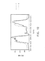
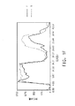
電界紡糸ナノファイバー多孔質基材によって強化された電解質膜の製造分野における研究が着手されている(例えば、Journal of Membrane Science 367(2011年)296−305を参照されたい)。0.03〜0.08(S/cm)の範囲のプロトン伝導度が報告されており、Nafion(登録商標)112膜と比較されている。プロトン伝導度(図8、303ページ)は、スルホン化度に依存していた(用語「S6.0NFPS」、S6.5NFPS」などで表され、これは、「SPPO」(スルホン化ポリ(2,6−ジメチルフェニレンオキシド))を得るために親PPOポリマーのスルホン化に使用されるスルホン化試薬の量を表している。 Research in the field of producing electrolyte membranes reinforced by electrospun nanofiber porous substrates has been undertaken (see, for example, Journal of Membrane Science 367 (2011) 296-305). Proton conductivity in the range of 0.03 to 0.08 (S / cm) has been reported and compared to Nafion® 112 membranes. Proton conductivity (FIG. 8, page 303) was dependent on the degree of sulfonation (terms “S6.0NFPS”, S6.5NFPS ”etc.), which is represented by“ SPPO ”(sulfonated poly (2, 6 represents the amount of sulfonation reagent used for sulfonation of the parent PPO polymer to obtain 6-dimethylphenylene oxide)).
しかし、上記引用論文中、著者らは、電界紡糸ナノファイバー多孔質基材の導入によって生じる性能の低下を示すための、ニートのアイオノマーの伝導度との直接比較を行っていない。参考論文番号48(J.Membrane Sci.,Vol.348,167−173(2010年))を見ると、3種類のSPPO膜プロトン伝導度データが172ページの表1に示されている。元のSPPO膜の伝導度は0.130S/cmである。構造を架橋させるための熱処理後、伝導度は0.1275S/cmである。 However, in the cited paper, the authors do not make a direct comparison with the conductivity of neat ionomers to show the performance degradation caused by the introduction of electrospun nanofiber porous substrates. Looking at reference article number 48 (J. Membrane Sci., Vol. 348, 167-173 (2010)), three types of SPPO membrane proton conductivity data are shown in Table 1 on page 172. The conductivity of the original SPPO film is 0.130 S / cm. After heat treatment to crosslink the structure, the conductivity is 0.1275 S / cm.
これらの研究論文の間でニートのアイオノマーと強化された膜とを比較すると、強化膜/ニートポリマーの伝導度の比の最低値は、0.03/0.13=0.23となり;分数で表すと1/4未満となることが分かる。強化膜/ニートポリマーの伝導度の比の最高値は0.08/0.1275=0.627となり;分数で表すと2/3未満となる。 Comparing the neat ionomer and the reinforced membrane among these research papers, the lowest value of the reinforced membrane / neat polymer conductivity ratio is 0.03 / 0.13 = 0.23; in fractions It can be seen that it is less than 1/4. The maximum value of the reinforced membrane / neat polymer conductivity ratio is 0.08 / 0.1275 = 0.627; in fractions, it is less than 2/3.
報告されている他の複合膜でも、成分アイオノマーと比較して伝導度が顕著に低下することが開示されている。例えば、Choiら(Journal of Power Sources,180,(2008年),167−171)は、Nafion(登録商標)を電界紡糸ポリフッ化ビニリデンに含浸させた複合膜の議論において伝導度が1桁低下することを認めている(即ち、成分のNafion(登録商標)N115アイオノマーの32mS/cmと比較して、Nafion(登録商標)を電界紡糸ポリフッ化ビニリデンに含浸させた複合膜の伝導度は1.55〜2.25mS/cmである)。本明細書で更に説明するように、このような複合膜は、成分のイオン交換ポリマーと比較して伝導度の低下が生じない本明細書で報告される本発明の複合膜とは構造的に異なることが明らかである。 It has been disclosed that the conductivity of other composite membranes reported is significantly lower than that of component ionomers. For example, Choi et al. (Journal of Power Sources, 180, (2008), 167-171) reduce conductivity by an order of magnitude in the discussion of composite membranes in which Nafion® is impregnated with electrospun polyvinylidene fluoride. (Ie, compared to the component Nafion® N115 ionomer of 32 mS / cm, the conductivity of the composite membrane impregnated with electrospun polyvinylidene fluoride with Nafion® is 1.55. ~ 2.25 mS / cm). As further described herein, such composite membranes are structurally different from the composite membranes of the present invention reported herein that do not experience a decrease in conductivity compared to the component ion exchange polymer. Clearly different.
高プロトン伝導度は、燃料電池中のプロトン交換膜の重要なパラメータである。強化膜/ニートポリマーの伝導度の比が2/3を超え、更により望ましくは、強化材の混入による、強化材量(体積分率による)に対する不釣り合いな伝導度の低下が実質的に生じない複合膜が得られることが望ましい。 High proton conductivity is an important parameter for proton exchange membranes in fuel cells. The conductivity ratio of the reinforcing membrane / neat polymer exceeds 2/3, and even more desirably, the incorporation of the reinforcing material substantially causes an unbalanced decrease in conductivity with respect to the amount of reinforcing material (depending on the volume fraction). It is desirable to obtain a composite membrane that does not have any.
本発明は、改善された膜を提供し、相対湿度及び温度の種々の条件下、並びに多孔質強化マトリックスの存在下で、厚さ方向(through−plane)伝導度、電気出力、膨潤などの得られる性質が改善される膜の製造方法を提供する。 The present invention provides an improved membrane that provides for through-plane conductivity, electrical output, swelling, etc. under various conditions of relative humidity and temperature, and in the presence of a porous reinforced matrix. A method for producing a membrane with improved properties is provided.
本発明は、所望の厚さを有しながら、良好な伝導度、発電特性、耐温度性(例えば、高温で機能する能力)、機械的強度、及び寸法変化に対する抵抗性を以前として示す複合膜も提供する。 The present invention provides a composite membrane that exhibits good conductivity, power generation characteristics, temperature resistance (eg, ability to function at high temperatures), mechanical strength, and resistance to dimensional changes while having the desired thickness. Also provide.
本発明は、強化膜/ニートポリマーの伝導度の比が2/3を超える複合膜を提供し、または別の実施形態においては、複合膜の伝導度は、前記少なくとも1種類のカチオン交換ポリマーのカチオン伝導度に、1−1.2×(前記不織ウェブ材料の体積分率)の調節因子を乗じた値以下となる。 The present invention provides a composite membrane having a reinforced membrane / neat polymer conductivity ratio of greater than 2/3, or in another embodiment, the conductivity of the composite membrane is that of the at least one cation exchange polymer. It is below the value obtained by multiplying the cation conductivity by an adjustment factor of 1-1.2 × (volume fraction of the nonwoven web material).
本発明によって、多くの問題が解決され、多くの改善が得られる。これらの中で、本発明により得られる多孔質強化マトリックスは崩壊/空隙の問題が解消されるが、その理由は、本発明の強化材料は、アイオノマー分散体を含浸させた複合フィルムから溶媒を蒸発させる間の崩壊力に耐える性質を有するからである。 The present invention solves many problems and provides many improvements. Among these, the porous reinforced matrix obtained by the present invention solves the problem of collapse / void, because the reinforced material of the present invention evaporates the solvent from the composite film impregnated with the ionomer dispersion. This is because it has a property to withstand the collapse force during the process.
ある実施形態においては、本発明は、複合ポリマーカチオン交換膜であって、(a)少なくとも約65%の多孔度及び10μm以下の平均孔径を有し、互いに反対側の表面を有する不織ウェブ材料と、(b)少なくとも1種類のカチオン交換ポリマーであって、互いに反対側の表面の間の中間点において少なくとも40パーセントの体積分率を有するように、前記不織ウェブの前記互いに反対側の表面の間に含浸させた、少なくとも1種類のカチオン交換ポリマーとを含む、複合ポリマーカチオン交換膜を提供する。 In certain embodiments, the present invention provides a composite polymer cation exchange membrane comprising: (a) a nonwoven web material having a porosity of at least about 65% and an average pore size of 10 μm or less, and surfaces opposite to each other. And (b) at least one cation exchange polymer, wherein the opposite surfaces of the nonwoven web have a volume fraction of at least 40 percent at a midpoint between the opposite surfaces. A composite polymer cation exchange membrane is provided comprising at least one cation exchange polymer impregnated between.
本発明は、このような強化ポリマーイオン交換膜の製造方法を提供する。 The present invention provides a method for producing such a reinforced polymer ion exchange membrane.
本発明は、より低コストの強化材料及びより低コストのアイオノマーを使用しながら、良好な膜性能を実現できる、このような強化ポリマーイオン交換膜の製造方法を提供する。 The present invention provides a method for producing such a reinforced polymer ion exchange membrane that can achieve good membrane performance while using lower cost reinforcing materials and lower cost ionomers.
本発明は、複合ポリマーイオン交換膜であって、互いに反対側の表面を有し:(a)非伝導性非圧密化ポリマー繊維を含む多孔質不織ウェブ材料と;(b)少なくとも1種類のイオン交換ポリマーであって、複合膜全体にわたって実質的に等しい体積分率を有し、互いに反対側の表面の間での体積分率が50パーセントを超えるように、前記複合膜の前記互いに反対側の表面の間に含浸させた、少なくとも1種類のイオン交換ポリマーとを含む、複合ポリマーイオン交換膜を提供する。 The present invention is a composite polymer ion exchange membrane having opposite surfaces: (a) a porous nonwoven web material comprising non-conductive non-consolidated polymer fibers; and (b) at least one type An ion exchange polymer having substantially equal volume fractions throughout the composite membrane, the opposite sides of the composite membrane such that the volume fraction between opposite surfaces exceeds 50 percent. A composite polymer ion exchange membrane is provided comprising at least one ion exchange polymer impregnated between the surfaces.
一実施形態においては、イオン交換ポリマーはカチオン交換ポリマーである。 In one embodiment, the ion exchange polymer is a cation exchange polymer.
一実施形態においては、イオン交換ポリマーはアニオン交換ポリマーである。 In one embodiment, the ion exchange polymer is an anion exchange polymer.
一実施形態においては、多孔質不織ウェブ材料は、少なくとも約65%の多孔度及び10μm以下の平均孔径を有する。 In one embodiment, the porous nonwoven web material has a porosity of at least about 65% and an average pore size of 10 μm or less.
一実施形態においては、ウェブ材料は、ポリイミド、ポリエーテルスルホン(PES)、及びポリフッ化ビニリデン(PVDF)からなる群から選択される。 In one embodiment, the web material is selected from the group consisting of polyimide, polyethersulfone (PES), and polyvinylidene fluoride (PVDF).
一実施形態においては、ウェブ材料は、溶融紡糸ポリマー及び溶液紡糸ポリマーからなる群から選択される。 In one embodiment, the web material is selected from the group consisting of melt spun polymers and solution spun polymers.
一実施形態においては、複合ポリマーイオン交換ポリマーは、カチオン交換ポリマー及びアニオン交換ポリマーの両方を含む。 In one embodiment, the composite polymer ion exchange polymer comprises both a cation exchange polymer and an anion exchange polymer.
一実施形態においては、複合ポリマーイオン交換膜は80mS/cmを超えるイオン伝導度を有する。 In one embodiment, the composite polymer ion exchange membrane has an ionic conductivity greater than 80 mS / cm.
一実施形態においては、イオン交換ポリマーは、更に、前記ウェブ材料を含有せず、前記ウェブ互いに反対側の表面の少なくとも一方に接触するニート層を形成する。 In one embodiment, the ion exchange polymer further does not contain the web material and forms a neat layer that contacts at least one of the surfaces opposite the web.
一実施形態においては、複合ポリマーイオン交換膜は2〜500ミクロンの範囲内の厚さを有する。 In one embodiment, the composite polymer ion exchange membrane has a thickness in the range of 2 to 500 microns.
一実施形態においては、イオン交換ポリマーは、式−(O−CF2CFRf)a−(O−CF2)b−(CFR’f)cSO3M(式中、Rf及びR’fは、独立して、F、Cl、または1〜10個の炭素原子を有する過フッ素化アルキル基から選択され、a=0、1、または2、b=0〜1、及びc=0〜6であり、mは、水素、Li、Na、K、またはN(R1)(R2)(R3)(R4)であり、R1、R2、R3、及びR4は、同じまたは異なるものであって、H、CH3、またはC2H5である)で表される側鎖を有する高フッ素化炭素主鎖を含むイオン交換ポリマーから選択されるカチオン交換ポリマーを含む。 In one embodiment, the ion exchange polymer has the formula — (O—CF 2 CFRf) a — (O—CF 2 ) b — (CFR′f) c SO 3 M, wherein R f and R ′ f are Independently selected from F, Cl, or a perfluorinated alkyl group having 1 to 10 carbon atoms, with a = 0, 1, or 2, b = 0-1 and c = 0-6. M is hydrogen, Li, Na, K, or N (R 1 ) (R 2 ) (R 3 ) (R 4 ), and R 1 , R 2 , R 3 , and R 4 are the same or A cation exchange polymer selected from ion exchange polymers comprising a highly fluorinated carbon backbone having a side chain represented by H, CH 3 , or C 2 H 5 .
一実施形態においては、複合ポリマーイオン交換膜は:
(i)少なくとも部分フッ素化された多環芳香族ポリマー主鎖が式I:
In one embodiment, the composite polymer ion exchange membrane is:
(I) At least partially fluorinated polycyclic aromatic polymer backbone is of formula I:

(式中、
Aは、単結合、アルキレン、フルオロアルキレン、またはアリーレンであり、ハロゲン化物、アルキル、フルオロアルキル、及び/またはカチオン官能基で場合により置換されていてよく;
Bは、単結合、酸素、またはNRであり、Rは、H、アルキル、フルオロアルキル、またはアリールであり、ハロゲン化物、アルキル、架橋剤、及び/またはフルオロアルキルで場合により置換されていてよく;
Ra、Rb、Re、Rd、Rm、Rn、Rp、及びRqは、それぞれ独立して、水素、フッ素、架橋基、及びカチオン性官能基からなる群から選択され;
A、B、Ra、Rb、Rc、Rd、Rm、Rn、Rp、及びRqの少なくとも1つはフッ素化されている)
繰り返し単位を含む、及び
(ii)少なくとも部分フッ素化された多環芳香族ポリマー主鎖が、
(Where
A is a single bond, alkylene, fluoroalkylene, or arylene, optionally substituted with halide, alkyl, fluoroalkyl, and / or cationic functional groups;
B is a single bond, oxygen, or NR, R is H, alkyl, fluoroalkyl, or aryl, optionally substituted with halide, alkyl, crosslinker, and / or fluoroalkyl;
R a , R b , R e , R d , R m , R n , R p , and R q are each independently selected from the group consisting of hydrogen, fluorine, a bridging group, and a cationic functional group;
At least one of A, B, R a , R b , R c , R d , R m , R n , R p , and R q is fluorinated)
And (ii) at least partially fluorinated polycyclic aromatic polymer backbone,
(式中、Bは、単結合、酸素、またはNRであり、Rは、H、アルキル、フルオロアルキル、またはアリールであり、ハロゲン化物、アルキル、架橋剤、及び/またはフルオロアルキルで場合により置換されていてよい)
の繰り返し単位を含む、
からなる群から選択されるアニオン交換ポリマーを含む。
Wherein B is a single bond, oxygen, or NR, R is H, alkyl, fluoroalkyl, or aryl, optionally substituted with halide, alkyl, crosslinker, and / or fluoroalkyl. May be)
Containing repeating units of
An anion exchange polymer selected from the group consisting of:
一実施形態においては、イオン交換ポリマーは、複合ポリマーイオン交換膜中少なくとも60パーセントの体積分率を有する。 In one embodiment, the ion exchange polymer has a volume fraction of at least 60 percent in the composite polymer ion exchange membrane.
一実施形態においては、複合ポリマーイオン交換膜は、膜中に前記ウェブによる厚さ方向伝導度の低下(z軸)を示さない。 In one embodiment, the composite polymer ion exchange membrane does not show a decrease in thickness direction conductivity (z-axis) due to the web in the membrane.
一実施形態においては、複合ポリマーイオン交換膜の厚さ方向伝導度は、強化していない成分のイオン交換ポリマーの厚さ方向伝導度の少なくとも80%である。 In one embodiment, the thicknesswise conductivity of the composite polymer ion exchange membrane is at least 80% of the thicknesswise conductivity of the non-reinforced component ion exchange polymer.
本発明は、本発明の複合ポリマーイオン交換膜を含むフロー電池も提供する。 The present invention also provides a flow battery comprising the composite polymer ion exchange membrane of the present invention.
本発明は、本発明の複合ポリマーイオン交換膜を含む膜電極接合体、及び前記膜電極接合体を含む燃料電池も提供する。 The present invention also provides a membrane electrode assembly including the composite polymer ion exchange membrane of the present invention, and a fuel cell including the membrane electrode assembly.
本発明は、互いに反対側の表面を有する複合ポリマーイオン交換膜の製造方法であって:
(a)少なくとも1種類のイオン交換ポリマーを含む溶液または分散体を提供するステップと、
(b)非伝導性非圧密化ポリマー繊維を含む多孔質不織ウェブ材料を提供するステップと、
(c)前記溶液または分散体を前記ウェブに接触させるステップであって、乾燥させると、前記少なくとも1種類のイオン交換ポリマーが、前記不織ウェブの互いに反対側の表面の間に含浸され、前記少なくとも1種類のイオン交換ポリマーが、複合膜全体にわたって実質的に等しい体積分率を有し、互いに反対側の表面の間での体積分率が50パーセントを超えるように行われるステップとを含む、方法も提供する。
The present invention is a method of making a composite polymer ion exchange membrane having opposite surfaces:
(A) providing a solution or dispersion comprising at least one ion exchange polymer;
(B) providing a porous nonwoven web material comprising non-conductive, non-consolidated polymer fibers;
(C) contacting the solution or dispersion with the web, when dried, the at least one ion exchange polymer is impregnated between opposite surfaces of the nonwoven web; At least one ion-exchange polymer has a substantially equal volume fraction throughout the composite membrane, and the volume fraction between the opposite surfaces exceeds 50 percent. A method is also provided.
更に本発明は、80mS/cmを超えるイオン伝導度を有する複合ポリマーイオン交換膜が得られる前記方法も提供する。 The present invention further provides the above method, wherein a composite polymer ion exchange membrane having an ionic conductivity greater than 80 mS / cm is obtained.
電気化学セル用のポリマー電解質膜の製造方法であって:強化膜を提供するステップであって、強化膜は、複数のナノファイバーを含むナノウェブであり、ナノファイバーは、ある実施形態においては、完全芳香族ポリイミド、ポリエーテルスルホン、またはポリフッ化ビニリデンを含むことができ、強化膜は、カレンダー加工されないか、または軽くカレンダー加工されるステップと;強化膜にイオン交換ポリマーを含浸させるステップとを含む、方法が、本明細書に記載される。 A method for producing a polymer electrolyte membrane for an electrochemical cell comprising: providing a reinforced membrane, wherein the reinforced membrane is a nanoweb comprising a plurality of nanofibers, wherein the nanofibers are, in one embodiment, Can comprise fully aromatic polyimide, polyethersulfone, or polyvinylidene fluoride, and the reinforced membrane comprises a step that is not calendered or lightly calendered; and a step of impregnating the reinforced membrane with an ion exchange polymer The method is described herein.
本発明の電気化学セルは、燃料電池、電池、クロロアルカリセル、電解セル、センサー、電気化学キャパシタ、及び修飾電極などの当技術分野において周知のあらゆるものであってよい。燃料電池は、アニオン型またはカチオン型の燃料電池であってよく、メタノールまたは水素などのあらゆる燃料源を使用することができる。 The electrochemical cell of the present invention may be any well known in the art such as fuel cells, batteries, chloroalkali cells, electrolytic cells, sensors, electrochemical capacitors, and modified electrodes. The fuel cell can be an anionic or cationic fuel cell and any fuel source such as methanol or hydrogen can be used.
本明細書に記載の複合膜は、米国特許出願公開第2010/0003545号明細書に記載されるようなレドックスフロー電池中に使用することができる。その文献に記載されるレドックスフロー電池スタック設計は、例えば、電解質中に溶解させた反応物を含む反応物の組み合わせであってよい。一例は、負極にバナジウム反応物V(II)/V(III)またはV2+/V3+(アノライト)を含有し、正極にV(IV)/V(V)またはV4+/V5+(カソライト)を含有するスタックである。このような系中のアノライト及びカソライト反応物は、通常、硫酸中に溶解される。この種類の電池は、アノライト及びカソライトの両方がバナジウム種を含有するため、全バナジウム電池と呼ばれることが多い。本発明による複合膜を使用できるフロー電池中の反応物の別の組み合わせは、Sn(アノライト)/Fe(カソライト)、Mn(アノライト)/Fe(カソライト)、V(アノライト)/Ce(カソライト)、V(アノライト)/Br2(カソライト)、Fe(アノライト)/Br2(カソライト)、及びS(アノライト)/Br2(カソライト)である。動作可能なレドックスフロー電池の化学的性質及び系の更なる例が、米国特許第6,475,661号明細書に示されており、その内容全体が参照により本明細書に援用される。 The composite membrane described herein can be used in a redox flow battery as described in US 2010/0003545. The redox flow battery stack design described in that document may be a combination of reactants including, for example, reactants dissolved in an electrolyte. An example contains the vanadium reactant V (II) / V (III) or V2 + / V3 + (anolyte) at the negative electrode and V (IV) / V (V) or V4 + / V5 + (catholyte) at the positive electrode. Is a stack containing The anolyte and catholyte reactants in such systems are usually dissolved in sulfuric acid. This type of battery is often referred to as an all-vanadium battery because both anolyte and catholyte contain vanadium species. Other combinations of reactants in a flow battery that can use the composite membrane according to the present invention are Sn (anolyte) / Fe (catholyte), Mn (anolyte) / Fe (catholyte), V (anolyte) / Ce (catholyte), V (anolite) / Br 2 (catholite), Fe (anolite) / Br 2 (catholite), and S (anolite) / Br 2 (catholite). Further examples of operable redox flow battery chemistries and systems are shown in US Pat. No. 6,475,661, the entire contents of which are hereby incorporated by reference.
定義
本明細書において、量、濃度、或いはその他の値またはパラメータが、ある範囲、好ましい範囲、或いは一連の好ましい上限値及び好ましい下限値のいずれかで示される場合、これは、複数の範囲が別々に開示されているかどうかとは無関係に、任意の範囲の上限または好ましい値と、及び任意の範囲の下限または好ましい値との任意の組から形成されるあらゆる組から形成されるすべての範囲を特に開示するものと理解すべきである。本明細書にある数値範囲が記載される場合、特に他の記載がなければ、その範囲は、その端点、並びにその範囲内のすべての整数及び分数を含むことが意図される。ある範囲が定義される場合、記載の特定の値に本発明の範囲が限定されることを意図するものではない。
Definitions In this specification, when an amount, concentration, or other value or parameter is indicated by either a range, a preferred range, or a series of preferred upper and lower limits, this means that multiple ranges are separated. All ranges formed from any set formed from any set of upper limits or preferred values of any range and lower limits or preferred values of any range, regardless of whether disclosed in It should be understood as disclosed. Where a numerical range is stated herein, unless otherwise stated, the range is intended to include its endpoints and all integers and fractions within that range. When a range is defined, it is not intended that the scope of the invention be limited to the specific values recited.
本発明の目的では、用語「膜」は、燃料電池技術分野において一般に使用される用語であり、より一般に使用される専門用語であるが同一の物品を意味する用語「フィルム」または「シート」と同義である。 For the purposes of the present invention, the term “membrane” is a term commonly used in the field of fuel cell technology, and is a more commonly used term, but with the terms “film” or “sheet” meaning the same article. It is synonymous.
本明細書において使用される場合、例えばキャスト膜または押出フィルムの説明に関して使用される略語「MD」及び「TD」は、当技術分野の慣習に従い、それぞれ「縦方向」及び「横方向」の略である。 As used herein, for example, the abbreviations “MD” and “TD” used in connection with the description of cast or extruded films are the abbreviations for “longitudinal” and “lateral”, respectively, in accordance with convention in the art. It is.
本明細書において、EWは、当量の略であり、1モル当量のNaOHを中和するために必要な酸の形態のポリマー(アイオノマー)の重量である。アイオノマーはイオン交換ポリマーである。 In this specification, EW is an abbreviation for equivalent weight, and is the weight of an acid form polymer (ionomer) necessary to neutralize one molar equivalent of NaOH. An ionomer is an ion exchange polymer.
以下に定義される不織ウェブ及び不織ナノウェブの両方が、本発明の範囲内にあると考慮される。 Both nonwoven webs and nonwoven nanowebs defined below are considered to be within the scope of the present invention.
本明細書において使用される場合、用語「ナノウェブ」は、大きな部分がナノファイバーで構成される不織ウェブを意味する。大きな部分は、25%を超え、更には50%を超えるウェブ中の繊維がナノファイバーである事を意味し、ここで、この場合に使用される用語「ナノファイバー」は数平均直径が1000nm未満、更には800nm未満、更には約50nm〜500nmの間、更には約100〜400nmの間である繊維を意味する。円形ではない断面のナノファイバーの場合、この場合に使用される用語「直径」は最大断面寸法を意味する。本発明のナノウェブは、70%、または90%を超えるナノファイバーを有することもできるし、更には100%のナノファイバーを含有することもできる。 As used herein, the term “nanoweb” means a non-woven web composed largely of nanofibers. The larger part means that more than 25% and even more than 50% of the fibers in the web are nanofibers, where the term “nanofibers” is used in this case with a number average diameter of less than 1000 nm. , Or even less than 800 nm, even between about 50 nm and 500 nm, and even between about 100 and 400 nm. In the case of non-circular cross-section nanofibers, the term “diameter” used in this case means the maximum cross-sectional dimension. The nanoweb of the present invention can have more than 70%, or more than 90% nanofibers, or even 100% nanofibers.
本明細書において、「圧密化されていない」または「非圧密化」ウェブ材料は、製造後に、例えばカレンダー加工によって、或いはポリマー繊維を互いに固定または溶融融合させることによって圧縮されていないウェブ材料である。「カレンダー加工」は、2つのロールの間のニップにウェブを通すことなどによってウェブ材料を圧縮するプロセスである。このようなロールは、互いに接触する場合もあるし、ロール表面の間で一定または可変の間隙が存在する場合もある。非圧密化は、室温における軽いカレンダー加工を含む場合があり、より好ましくはカレンダー加工を含まない。本発明において、あらゆる軽いカレンダー加工は、ウェブ材料の多孔度が少なくとも65%、好ましくは少なくとも70%、または少なくとも75%、より好ましくは少なくとも80%、または少なくとも85%、更には90%を超えて維持されるのに十分穏やかなものである必要がある。 As used herein, an “unconsolidated” or “unconsolidated” web material is a web material that has not been compressed after manufacture, for example, by calendering, or by fixing or melt fusing polymer fibers together. . “Calendaring” is a process of compressing web material, such as by passing the web through a nip between two rolls. Such rolls may contact each other and there may be a constant or variable gap between the roll surfaces. Non-consolidation may include light calendering at room temperature, and more preferably does not include calendering. In the present invention, any light calendering has a web material porosity of at least 65%, preferably at least 70%, or at least 75%, more preferably at least 80%, or at least 85%, or even more than 90%. It needs to be gentle enough to be maintained.
本明細書において、「実質的にすべての官能基が式−SO3M(式中、MはHである)で表される」という表現(及び類似の表現)は、−SO3Hの形態であるそのような官能基のパーセント値が、例えば少なくとも98%などの100%に近い、または等しいことを意味する。 As used herein, the expression (and similar expressions) that “substantially all functional groups are represented by the formula —SO 3 M (wherein M is H)” is a form of —SO 3 H. Means that the percentage value of such functional groups is close to or equal to 100%, for example at least 98%.
不織ウェブ材料の多孔度は、100×(1.0−固体度)に等しく、不織ウェブ材料構造中の自由体積のパーセント値として表され、固体度は、不織ウェブ材料構造中の固定材料の分率として表される。 The porosity of the nonwoven web material is equal to 100 × (1.0−solidity) and is expressed as a percentage of the free volume in the nonwoven web material structure, where the solidity is fixed in the nonwoven web material structure. Expressed as a fraction of material.
「平均孔径」は、ASTM Designation E 1294−89,“Standard Test Method for Pore Size Characteristics of Membrane Filters Using Automated Liquid Porosimeter”に準拠して測定される。異なる大きさ(8、20、または30mmの直径)の個別のサンプルを低表面張力流体(1,1,2,3,3,3−ヘキサフルオロプロペン、または表面張力が16ダイン/cmの“Galwick”)でぬらし、ホルダーに入れ、空気の圧力差を生じさせて、サンプルから流体を除去する。湿潤状態の流れが乾燥状態の流れ(溶媒でぬらしていない場合の流れ)の半分となる圧力差を使用して、供給されるソフトウェアで平均孔径が計算される。 “Average pore size” is measured in accordance with ASTM Designation E 1294-89, “Standard Test Method for Pore Size Characteristic of Membrane Filters Using Liquid Liquid”. Separate samples of different sizes (8, 20, or 30 mm diameter) can be used with low surface tension fluids (1,1,2,3,3,3-hexafluoropropene, or “Galwick” with a surface tension of 16 dynes / cm. )), Place in holder and create air pressure difference to remove fluid from sample. The average pore size is calculated with the supplied software using the pressure difference where the wet stream is half that of the dry stream (the stream when not wetted with solvent).
「バブルポイント」は、サンプル中の最大孔径の尺度の1つであり、ASTM Designation F316,”Standard Test Methods for Pore Size Characteristics of Membrane Filters by Bubble Point and Mean Flow Pore Test“に準拠して測定される。個別のサンプル(8、20または30mmの直径)が前述のように表面張力流体で濡らされる。サンプルをホルダーに入れた後、圧力差(空気)を生じさせ、流体をサンプルから除去する。バブルポイントは、圧縮空気圧がサンプルシートに加えられた後の最初の開放細孔であり、供給元より供給されるソフトウェアを用いて計算される。 “Bubble Point” is one of the maximum pore size measures in a sample and is measured in accordance with ASTM Designation F316, “Standard Test Methods for Pore Size Ceramics of Membrane Filters by Membrane Filter. . Individual samples (8, 20 or 30 mm diameter) are wetted with surface tension fluid as described above. After placing the sample in the holder, a pressure differential (air) is created and the fluid is removed from the sample. The bubble point is the first open pore after compressed air pressure is applied to the sample sheet and is calculated using software supplied by the supplier.
本明細書において、非伝導性は、カチオン種またはアニオン種、より典型的には水素イオン(プロトン)が非伝導性であることを意味する。 As used herein, non-conductive means that a cationic or anionic species, more typically a hydrogen ion (proton) is non-conductive.
ナノファイバー及びナノウェブの概略
ナノウェブは、エレクトロブロー、電界紡糸、及びメルトブローからなる群から選択される方法によって製造することができる。ポリマー溶液のエレクトロブローによるナノウェブの形成は、米国特許第7,618,579号明細書に対応するKimの国際公開第03/080905号パンフレットに詳細に記載されており、その開示全体が参照により本明細書に援用される。要約するとエレクトロブロー法は、特定の溶媒中に溶解させたポリマー溶液を紡糸ノズルに供給するステップと;高電圧が印加される紡糸ノズルを介してポリマー溶液を吐出しながら、紡糸ノズルの下端から圧縮空気を注入するステップと;紡糸ノズルの下方の接地した吸引コレクター上にポリマー溶液を紡糸するステップとを含む。
Overview of Nanofibers and Nanowebs Nanowebs can be produced by a method selected from the group consisting of electroblowing, electrospinning, and meltblowing. The formation of nanowebs by electroblowing polymer solutions is described in detail in Kim's WO 03/080905, corresponding to US Pat. No. 7,618,579, the entire disclosure of which is hereby incorporated by reference Incorporated herein by reference. In summary, the electroblowing method includes supplying a polymer solution dissolved in a specific solvent to a spinning nozzle; and compressing from the lower end of the spinning nozzle while discharging the polymer solution through the spinning nozzle to which a high voltage is applied. Injecting air; spinning the polymer solution onto a grounded suction collector below the spinning nozzle.
米国特許第7,618,579号明細書には、記載される方法に好適なポリマーとして、ポリイミド、ナイロン、ポリアラミド、ポリベンゾイミダゾール、ポリエーテルイミド、ポリアクリロニトリル、PET(ポリエチレンテレフタレート)、ポリプロピレン、ポリアニリン、ポリエチレンオキシド、PEN(ポリエチレンナフタレート)、PBT(ポリブチレンテレフタレート)、SBR(スチレンブタジエンゴム)、ポリスチレン、PVC(ポリ塩化ビニル)、ポリビニルアルコール、PVDF(ポリフッ化ビニリデン)、ポリビニルブチレン、並びにそれらのコポリマーまたは誘導体化合物を挙げることができると開示されている。本発明実施形態においては、ナノファイバーは、完全芳香族ポリイミド、ポリエーテルスルホン、またはポリフッ化ビニリデンを含むことができる。 U.S. Pat. No. 7,618,579 describes suitable polymers for the described method as polyimide, nylon, polyaramid, polybenzimidazole, polyetherimide, polyacrylonitrile, PET (polyethylene terephthalate), polypropylene, polyaniline. , Polyethylene oxide, PEN (polyethylene naphthalate), PBT (polybutylene terephthalate), SBR (styrene butadiene rubber), polystyrene, PVC (polyvinyl chloride), polyvinyl alcohol, PVDF (polyvinylidene fluoride), polyvinyl butylene, and their It is disclosed that copolymer or derivative compounds can be mentioned. In embodiments of the present invention, the nanofiber can include fully aromatic polyimide, polyethersulfone, or polyvinylidene fluoride.
一実施形態においては、ナノファイバーは1種類以上の完全芳香族ポリイミドから本質的になる。例えば、使用されるナノファイバーは、80重量%を超える1種類以上の完全芳香族ポリイミド、90重量%を超える1種類以上の完全芳香族ポリイミド、95重量%を超える1種類以上の完全芳香族ポリイミド、99重量%を超える1種類以上の完全芳香族ポリイミド、99.9重量%を超える1種類以上の完全芳香族ポリイミド、または100重量%の1種類以上の完全芳香族ポリイミドから製造することができる。本明細書において使用される場合、用語「完全芳香族ポリイミド」は、1375cm−1におけるイミドC−N赤外吸光度の、1500cm−1におけるp−置換C−H赤外吸光度に対する比が0.51を超え、ポリマー主鎖中の隣接するフェニル環の間の結合の少なくとも95%が共有結合またはエーテル結合のいずれかによって生じるポリイミドを特に意味する。上記結合の最大25%、好ましくは最大20%、最も好ましくは最大10%が、脂肪族炭素、スルフィド、スルホン、ホスフィド、またはホスホンの官能基、或いはそれらの組み合わせによって生じてよい。ポリマー主鎖を構成する芳香環の最大5%は、脂肪族炭素、スルフィド、スルホン、ホスフィド、またはホスホンの環置換基を有することができる。好ましくは、本発明における使用に好適な完全芳香族ポリイミドは、脂肪族炭素、スルフィド、スルホン、ホスフィド、及びホスホンを含有しない。 In one embodiment, the nanofiber consists essentially of one or more fully aromatic polyimides. For example, the nanofibers used are more than 80% by weight of one or more fully aromatic polyimides, more than 90% by weight of one or more fully aromatic polyimides, more than 95% by weight of one or more fully aromatic polyimides , More than 99% by weight of one or more fully aromatic polyimides, more than 99.9% by weight of one or more fully aromatic polyimides, or 100% by weight of one or more fully aromatic polyimides. . As used herein, the term “fully aromatic polyimide” has a ratio of imide C—N infrared absorbance at 1375 cm −1 to p-substituted C—H infrared absorbance at 1500 cm −1 of 0.51. In particular, it means a polyimide in which at least 95% of the bonds between adjacent phenyl rings in the polymer backbone are formed by either covalent bonds or ether bonds. Up to 25%, preferably up to 20%, and most preferably up to 10% of the linkages may be generated by aliphatic carbon, sulfide, sulfone, phosphide, or phosphone functional groups, or combinations thereof. Up to 5% of the aromatic rings making up the polymer backbone can have aliphatic carbon, sulfide, sulfone, phosphide, or phosphone ring substituents. Preferably, fully aromatic polyimides suitable for use in the present invention do not contain aliphatic carbon, sulfides, sulfones, phosphides, and phosphones.
本発明における使用に好適なポリイミドナノウェブは、ポリアミド酸ナノウェブのイミド化によって調製することができ、ここで、ポリアミド酸は、1種類以上の芳香族二無水物と1種類以上の芳香族ジアミンとの反応によって調製される縮合ポリマーである。好適な芳香族二無水物としては、ピロメリット酸二無水物(PMDA)、ビフェニルテトラカルボン酸二無水物(BPDA)、及びそれらの混合物があげられるが、それらに限定されるものではない。好適なジアミンとしては、オキシジアニリン(ODA)、1,3−ビス(4−アミノフェノキシ)ベンゼン(RODA)、及びそれらの混合物が挙げられるが、これらに限定されるものではない。典型的な二無水物としては、ピロメリット酸二無水物、ビフェニルテトラカルボン酸二無水物、及びそれらの混合物が挙げられる。典型的なジアミンとしては、オキシジアニリン、1,3−ビス(4−アミノフェノキシ)ベンゼン、及びそれらの混合物が挙げられ、より典型的にはPMDA及びODAが挙げられる。 Polyimide nanowebs suitable for use in the present invention can be prepared by imidization of polyamic acid nanowebs, wherein the polyamic acid comprises one or more aromatic dianhydrides and one or more aromatic diamines. Is a condensation polymer prepared by reaction with Suitable aromatic dianhydrides include, but are not limited to, pyromellitic dianhydride (PMDA), biphenyltetracarboxylic dianhydride (BPDA), and mixtures thereof. Suitable diamines include, but are not limited to, oxydianiline (ODA), 1,3-bis (4-aminophenoxy) benzene (RODA), and mixtures thereof. Typical dianhydrides include pyromellitic dianhydride, biphenyltetracarboxylic dianhydride, and mixtures thereof. Typical diamines include oxydianiline, 1,3-bis (4-aminophenoxy) benzene, and mixtures thereof, more typically PMDA and ODA.
本発明のポリアミド酸ナノウェブのイミド化方法においては、ポリアミド酸は、最初に溶液中で調製され、典型的な溶媒はジメチルアセトアミド(DMAC)またはジメチルホルムアミド(DMF)である。好適な方法の1つでは、Kimらの国際公開第03/080905号パンフレットに詳細に記載されるように、エレクトロブロー法によってポリアミド酸の溶液からナノウェブが形成される。 In the imidization method of the polyamic acid nanoweb of the present invention, the polyamic acid is first prepared in solution and typical solvents are dimethylacetamide (DMAC) or dimethylformamide (DMF). In one suitable method, nanowebs are formed from a solution of polyamic acid by electroblowing as described in detail in Kim et al., WO 03/080905.
こうして形成されたポリアミド酸ナノウェブのイミド化は、最初に、窒素パージした真空オーブン中約100℃の温度でナノウェブの溶媒抽出を行うことによって好都合に行うことができ;抽出後、次にナノウェブを200〜475℃の温度で約10分以下、好ましくは5分以下、より好ましくは2分以下、更により好ましくは5秒以下加熱することで、ナノウェブが十分にイミド化される。好ましくはイミド化プロセスは、ポリアミド酸(PAA)ナノウェブを第1の温度及び第2の温度の範囲内の温度で、5秒〜5分の範囲内の時間加熱して、ポリイミド繊維を形成することを含み、第1の温度はポリアミド酸のイミド化温度であり、第2の温度はポリイミドの分解温度である。 Imidization of the polyamic acid nanoweb thus formed can be conveniently performed by first performing solvent extraction of the nanoweb in a nitrogen purged vacuum oven at a temperature of about 100 ° C .; Heating the web at a temperature of 200 to 475 ° C. for about 10 minutes or less, preferably 5 minutes or less, more preferably 2 minutes or less, and even more preferably 5 seconds or less sufficiently imidizes the nanoweb. Preferably, the imidization process heats the polyamic acid (PAA) nanoweb at a temperature in the range of the first temperature and the second temperature for a time in the range of 5 seconds to 5 minutes to form a polyimide fiber. The first temperature is the imidization temperature of the polyamic acid, and the second temperature is the decomposition temperature of the polyimide.
本発明の方法は、更に、こうして得られたポリアミド酸繊維を、第1の温度及び第2の温度の範囲内の温度で、5秒〜5分、または5秒〜4分、または5秒〜3分、または5秒〜30秒の範囲内の時間加熱して、ポリイミド繊維を形成することを含むことができる。第1の温度は、ポリアミド酸のイミド化温度である。本発明の目的では、特定のポリアミド酸繊維のイミド化温度は、500℃未満の温度であり、その温度で50℃/分の加熱速度で熱重量(TGA)分析を行うと、%重量減/℃は、重量%の単位で±0.005%及び±0.05℃の精度で、1.0未満、好ましくは0.5未満まで減少する。第2の温度は、特定のポリアミド酸繊維から形成されたポリイミド繊維の分解温度である。 The method of the present invention further provides the polyamic acid fiber thus obtained at a temperature within the range of the first temperature and the second temperature for 5 seconds to 5 minutes, or 5 seconds to 4 minutes, or 5 seconds to Heating for 3 minutes, or a time in the range of 5 seconds to 30 seconds, can include forming polyimide fibers. The first temperature is the imidization temperature of the polyamic acid. For the purposes of the present invention, the imidization temperature of a particular polyamic acid fiber is less than 500 ° C., and thermogravimetric (TGA) analysis at that temperature at a heating rate of 50 ° C./min results in% weight loss / The ° C is reduced to less than 1.0, preferably less than 0.5, with an accuracy of ± 0.005% and ± 0.05 ° C in units of weight percent. The second temperature is a decomposition temperature of the polyimide fiber formed from the specific polyamic acid fiber.
好適な方法の1つでは、ポリアミド酸繊維は、室温及びイミド化温度の範囲内の温度で予備加熱され、その後、イミド化温度及び分解温度の範囲内の温度でポリアミド酸繊維を加熱するステップが行われる。イミド化温度より低温に予備加熱するこの追加のステップによって、ポリアミド酸繊維中に存在する残留溶媒をゆっくり除去することができ、イミド化温度以上に加熱した場合に溶媒蒸気が急激に除去され高濃度となることで突発的な火災が発生する危険性が回避される。 In one preferred method, the polyamic acid fiber is preheated at a temperature within the range of room temperature and imidization temperature, and then heating the polyamic acid fiber at a temperature within the range of imidization temperature and decomposition temperature. Done. This additional step of preheating below the imidization temperature allows the residual solvent present in the polyamic acid fiber to be slowly removed, and when heated above the imidization temperature, the solvent vapor is rapidly removed and the high concentration This avoids the risk of a sudden fire.
ポリアミド酸繊維からポリイミド繊維への熱変換のステップは、対流式オーブン、真空オーブン、赤外線オーブン中で、空気中、或いはアルゴンまたは窒素などの不活性雰囲気中での加熱などのあらゆる好適な技術を使用して行うことができる。好適なオーブンは、1つの温度に設定することができるし、または複数の温度ゾーンを有し、各温度ゾーンを異なる温度に設定することもできる。一実施形態においては、加熱は、バッチプロセスにおいて段階的に行うことができる。別の一実施形態においては、加熱は、サンプルを温度勾配に曝露することが可能な連続プロセスで行うことができる。ある実施形態においては、ポリアミド酸繊維は、60℃/分〜250℃/秒の範囲の速度、または250℃/分〜250℃/秒の範囲の速度で加熱される。 The heat conversion step from polyamic acid fiber to polyimide fiber uses any suitable technique such as heating in air or in an inert atmosphere such as argon or nitrogen in a convection oven, vacuum oven, infrared oven. Can be done. Suitable ovens can be set to one temperature or have multiple temperature zones, each temperature zone can be set to a different temperature. In one embodiment, the heating can be performed stepwise in a batch process. In another embodiment, the heating can be performed in a continuous process that allows the sample to be exposed to a temperature gradient. In some embodiments, the polyamic acid fiber is heated at a rate in the range of 60 ° C./min to 250 ° C./sec, or a rate in the range of 250 ° C./min to 250 ° C./sec.
一実施形態においては、ポリアミド酸繊維は、各ゾーンが異なる温度に設定されるマルチゾーン赤外線オーブン中で加熱される。別の一実施形態においては、すべてのゾーンが同じ温度に設定される。別の一実施形態においては、赤外線オーブンは、コンベヤベルトの上及び下に赤外線ヒーターを更に含む。本発明における使用に好適な赤外線オーブンの更なる一実施形態においては、各温度ゾーンは、室温及び第4の温度の範囲内の温度に設定され、第4の温度は、第2の温度よりも少なくとも150℃高い。各ゾーンの温度は、個別のポリアミド酸、曝露時間、繊維直径、放射源の間の距離、残留溶媒含有量、パージ空気の温度及び流量、繊維ウェブ坪量(坪量は、1平方メートル当たりのグラム数の単位での材料の重量である)によって決定されることに留意されたい。例えば、従来のアニール範囲は、PMDA/ODAの場合で400〜500℃であるが、BPDA/RODAの場合は約200℃であり、BPDA/RODAは400℃まで加熱されると分解する。また、曝露時間を短縮することができるが、赤外線オーブンの温度が上昇し、逆の場合も同様となる。一実施形態においては、繊維ウェブはコンベヤベルト上でオーブンを通過し、コンベヤベルトの速度によって設定された5秒〜5分の範囲内の総時間で各ゾーンを通過する。別の一実施形態においては、繊維ウェブはコンベヤベルトによって支持されない。 In one embodiment, the polyamic acid fiber is heated in a multi-zone infrared oven where each zone is set to a different temperature. In another embodiment, all zones are set to the same temperature. In another embodiment, the infrared oven further includes infrared heaters above and below the conveyor belt. In a further embodiment of an infrared oven suitable for use in the present invention, each temperature zone is set to a temperature in the range of room temperature and a fourth temperature, the fourth temperature being greater than the second temperature. At least 150 ° C higher. The temperature of each zone is the individual polyamic acid, exposure time, fiber diameter, distance between radiation sources, residual solvent content, purge air temperature and flow rate, fiber web basis weight (basis weight is grams per square meter Note that it is determined by the weight of the material in units of numbers). For example, the conventional annealing range is 400 to 500 ° C. in the case of PMDA / ODA, but about 200 ° C. in the case of BPDA / RODA, and BPDA / RODA decomposes when heated to 400 ° C. Also, the exposure time can be shortened, but the temperature of the infrared oven increases and vice versa. In one embodiment, the fibrous web passes through the oven on the conveyor belt and passes through each zone for a total time in the range of 5 seconds to 5 minutes set by the speed of the conveyor belt. In another embodiment, the fibrous web is not supported by a conveyor belt.
ポリエーテスルホン(PES)のナノファイバー層は、国際公開第03/080905号明細書に記載されるようなエレクトロブロー法によって紡糸することができる。PES(HaEuntech Co,Ltd.Anyang SI,Koreaを介して入手可能、BASFの製品)は、N,Nジメチルアセトアミド(DMAc)(Samchun Pure Chemical Ind.Co Ltd,Gyeonggi−do,Koreaより入手可能)、及びN,Nジメチルホルムアミド(DMF)(HaEuntech Co,Ltd.Anyang SI,Koreaを介して入手可能、Samsung Fine Chemical Coの製品)の20/80溶媒中の25重量%溶液を使用して紡糸することができる。ポリマー及び溶液は溶液混合タンクに供給し、貯蔵槽に移すことができる。次に溶液を定量ポンプでエレクトロブロー紡糸パックに供給することができる。紡糸パックは、一連の紡糸ノズル及びガス注入ノズルを有することができる。紡糸口金は、電気的に絶縁して高電圧を印加することができる。類似の技術を使用して、ポリフッ化ビニリデンのナノファイバー層を製造することができる。 The nanofiber layer of polyethersulfone (PES) can be spun by an electroblowing method as described in WO 03/080905. PES (available through HaEuntech Co, Ltd. Anyang SI, Korea, a product of BASF) is N, N dimethylacetamide (DMAc) (available from Samchun Pure Chemical Ind. Co Ltd, Gyeonggi-do, Korea) And N, N dimethylformamide (DMF) (available through HaEuntech Co, Ltd. Anyang SI, Korea, a product of Samsung Fine Chemical Co) in a 25% by weight solution in 20/80 solvent. Can do. The polymer and solution can be fed into a solution mixing tank and transferred to a storage tank. The solution can then be fed to the electroblowing spin pack with a metering pump. The spin pack can have a series of spinning nozzles and gas injection nozzles. The spinneret can be electrically insulated and applied with a high voltage. Similar techniques can be used to produce nanofiber layers of polyvinylidene fluoride.
圧密化材料及び軽く圧密化された材料
本発明の実施形態においては、不織ウェブ材料は、約50nm〜約3000nmの間、例えば、約50nm〜約1000nm、または約100nm〜約800nm、または約200nm〜約800nm、または約200nm〜約600nm、或いはこれとは別に約1000nm〜約3000nmの範囲内の平均直径を有する微細なポリマー繊維の多孔質層を含むことができる。本発明の実施形態においては、不織ウェブ材料は、前述の定義のナノウェブであってよい。本発明の実施形態においては、これらの範囲内でありナノウェブに関して記載した範囲内である微細繊維は、高表面積を有する不織ウェブ材料構造が得られ、その結果アイオノマーの吸収が良好となり、本発明による複合膜が得られる。
Consolidated and lightly consolidated materials In embodiments of the present invention, the nonwoven web material is between about 50 nm and about 3000 nm, such as about 50 nm to about 1000 nm, or about 100 nm to about 800 nm, or about 200 nm. It can comprise a porous layer of fine polymer fibers having an average diameter in the range of from about 800 nm to about 800 nm, or from about 200 nm to about 600 nm, or alternatively from about 1000 nm to about 3000 nm. In embodiments of the present invention, the nonwoven web material may be a nanoweb as defined above. In embodiments of the present invention, fine fibers within these ranges and within the ranges described for nanowebs result in a nonwoven web material structure having a high surface area, resulting in good ionomer absorption and A composite membrane according to the invention is obtained.
本発明の実施形態においては、不織ウェブ材料は、平均流孔径(mean flow pore size)が約0.01μm〜約15μmの間、更には約0.1μm〜約10μmの間、更には約0.1μm〜約5μmの間、更には約0.01μm〜約5μmの間、または約0.01μm〜約1μmの間である。これらの平均孔径値は、材料を室温で軽くカレンダー加工した後に得られる場合もあるし、カレンダー加工が行われない実施形態では、カチオンまたはアニオン交換ポリマーが吸収される前に得られる場合もある。 In embodiments of the present invention, the nonwoven web material has a mean flow pore size between about 0.01 μm and about 15 μm, even between about 0.1 μm and about 10 μm, and even about 0. Between 1 μm and about 5 μm, even between about 0.01 μm and about 5 μm, or between about 0.01 μm and about 1 μm. These average pore size values may be obtained after light calendering of the material at room temperature, or in embodiments where no calendering is performed, may be obtained before the cation or anion exchange polymer is absorbed.
本発明の実施形態においては、不織ウェブ材料の多孔度は50%以上であり、別の実施形態においては65%以上、または70%以上、または75%以上であり、別の実施形態においては80%以上または85%以上である。これらの多孔度値は、材料を室温で軽くカレンダー加工した後に得られる場合もあるし、カレンダー加工が行われない実施形態では、カチオンまたはアニオン交換ポリマーが吸収される前に得られる場合もある。不織ウェブ材料の高い多孔度によって、アイオノマーの吸収も良好となり、本発明による複合膜が得られる。 In embodiments of the present invention, the nonwoven web material has a porosity of 50% or more, in another embodiment 65% or more, or 70% or more, or 75% or more, and in another embodiment. 80% or more or 85% or more. These porosity values may be obtained after light calendering of the material at room temperature, or in embodiments where no calendering is performed, may be obtained before the cation or anion exchange polymer is absorbed. Due to the high porosity of the nonwoven web material, the absorption of the ionomer is also good and the composite membrane according to the invention is obtained.
本発明の複合膜中に有用な不織ウェブ材料の厚さは、約1ミクロン〜500ミクロンの間、または約2ミクロン〜300ミクロンの間、または約2ミクロン〜100ミクロンの間、または約5ミクロン〜50ミクロンの間、更には約20ミクロン〜30ミクロンの間、更には約10ミクロン〜20ミクロンの間、更には約5ミクロン〜10ミクロンの間であってよい。不織ウェブ材料の厚さは、良好な機械的性質が得られ、同時にイオンの流動が良好となるのに十分な厚さである。 The thickness of the nonwoven web material useful in the composite membrane of the present invention is between about 1 micron and 500 microns, or between about 2 microns and 300 microns, or between about 2 microns and 100 microns, or about 5 microns. It may be between microns and 50 microns, even between about 20 microns and 30 microns, even between about 10 microns and 20 microns, even between about 5 microns and 10 microns. The thickness of the nonwoven web material is sufficient to obtain good mechanical properties and at the same time good ion flow.
本発明の不織ウェブ材料は、坪量が約1g/m2〜約90g/m2の間、更には約3g/m2〜約45g/m2の間、更には約5g/m2〜約40g/m2の間、更には約5g/m2〜約30g/m2の間、更には約5g/m2〜約20g/m2の間、更には約7g/m2〜約20g/m2の間、または約7g/m2〜約12g/m2の間、または約4g/m2〜約10g/m2の間である。
Nonwoven web material of the present invention, while a basis weight of about 1 g / m 2 ~ about 90 g / m 2, even between about 3 g / m 2 ~ about 45 g / m 2, even about 5
本発明の不織ウェブ材料は、Frazier通気度が約150cfm/ft2未満、更には約25cfm/ft2未満、更には約5cfm/ft2未満であってよい。一般に、Frazier通気度が高いほど、不織ウェブ材料のイオン抵抗性が低くなり、従ってFrazier通気度の高い不織ウェブ材料が望ましい場合がある。しかし、他の実施形態では、Frazier通気度レベルが低い場合もありうる。このように低いFrazier通気度レベル、即ち約1cfm/ft2以下では、シート材料の通気度は、Gurley Hill多孔度としてより正確に測定され、秒/100ccの単位で表される。Gurley Hill多孔度とFrazier通気度との近似的関係は:
Gurley Hill多孔度(単位秒)×Frazier(単位cfm/ft2)=3.1
と表すことができる。
Nonwoven web material of the present invention, Frazier air permeability of less than about 150cfm / ft 2, even less than about 25 cfm / ft 2, further can be less than about 5 CFM / ft 2. In general, the higher the Frazier air permeability, the lower the ionic resistance of the nonwoven web material, and therefore a nonwoven web material with a high Frazier air permeability may be desirable. However, in other embodiments, the Frazier air permeability level may be low. At such low Frazier air permeability levels, i.e. about 1 cfm / ft 2 or less, the air permeability of the sheet material is more accurately measured as Gurley Hill porosity and is expressed in units of seconds / 100 cc. The approximate relationship between Gurley Hill porosity and Frazier air permeability is:
Gurley Hill porosity (unit: second) × Frazier (unit: cfm / ft 2 ) = 3.1
It can be expressed as.
本発明のある実施形態においては、多孔質構造を維持し、構造的または機械的完全性を改善するためにポリマー微細繊維のポリマーを架橋させることが好ましく、それらの詳細は米国特許第7,112,389号明細書に開示されており、その開示全体が参照により本明細書に援用される。 In certain embodiments of the present invention, it is preferred to crosslink the polymer of polymer microfibers to maintain a porous structure and improve structural or mechanical integrity, details of which are described in US Pat. 389, the entire disclosure of which is hereby incorporated by reference.
本明細書に記載の方法において、製造された状態のナノウェブは、イオン交換ポリマーを含浸させる前に、例えば軽いカレンダー加工によって更に処理してもしなくてもよい。「カレンダー加工」は、2つのロールの間のニップにウェブを通すことなどにおってナノウェブを圧縮するプロセスである。このようなロールは、互いに接触する場合もあるし、ロール表面の間で一定または可変の間隙が存在する場合もある。イオン交換ポリマーを含浸させる前にナノウェブが軽くカレンダー加工される場合、このようなカレンダー加工は、後述のような最適な(a)多孔度、及び/または(b)平均孔径、及び/または(c)最大孔径が得られるように、軽くまたは最小限に行われる。場合により、ナノウェブは含浸後にカレンダー加工することもできる。 In the methods described herein, the prepared nanoweb may or may not be further processed, for example, by light calendering, prior to impregnation with the ion exchange polymer. “Calendaring” is a process of compressing a nanoweb, such as by passing the web through a nip between two rolls. Such rolls may contact each other and there may be a constant or variable gap between the roll surfaces. If the nanoweb is lightly calendered prior to impregnation with the ion exchange polymer, such calendering may be performed with optimal (a) porosity and / or (b) average pore size and / or (as described below). c) done lightly or minimally so as to obtain the maximum pore size. In some cases, the nanoweb can be calendered after impregnation.
軽いカレンダー加工が行われるニップロール圧は、約200ポンド/直線インチ未満、または約100ポンド/直線インチ未満の程度であってよい。 The nip roll pressure at which light calendering is performed may be on the order of less than about 200 pounds / linear inch, or less than about 100 pounds / linear inch.
前述のように、この目的は、含浸及び/または吸収が起こることが可能となり、完全に吸収されたナノウェブが得られるように、ナノウェブ材料開放細孔構造及び多孔度を維持することである。 As mentioned above, the aim is to maintain the nanoweb material open pore structure and porosity so that impregnation and / or absorption can occur and a fully absorbed nanoweb is obtained. .
本発明の実施形態においては、最大孔径は0.8μm〜20.0μmである。これらの最大孔径値は、材料を軽くカレンダー加工した後に得られる場合もあるし、カレンダー加工が行われない実施形態では、カチオンまたはアニオン交換ポリマーが吸収される前に得られる場合もある。 In the embodiment of the present invention, the maximum pore diameter is 0.8 μm to 20.0 μm. These maximum pore size values may be obtained after light calendering of the material, or in embodiments where no calendering is performed, may be obtained before the cation or anion exchange polymer is absorbed.
含浸及び/または吸収
含浸は、吸収または吸い込みとも呼ばれ、イオン交換ポリマーが、ナノウェブに吸収または取り込まれることを意味する。含浸は、通常、ナノウェブ中に所望の濃度で蓄積するのに十分な時間、ナノウェブをイオン交換ポリマーの溶液中に浸漬することによって行われる。或いは、イオン交換ポリマーは、対応するモノマーまたは低分子量オリゴマーの溶液をナノウェブに含浸させることによってその場で形成することができる。
Impregnation and / or absorption Impregnation, also called absorption or suction, means that the ion exchange polymer is absorbed or taken up by the nanoweb. Impregnation is usually performed by immersing the nanoweb in the solution of ion exchange polymer for a time sufficient to accumulate at the desired concentration in the nanoweb. Alternatively, the ion exchange polymer can be formed in situ by impregnating the nanoweb with a solution of the corresponding monomer or low molecular weight oligomer.
含浸が行われる温度及び時間は、ナノウェブの厚さ、上記溶液混合物中のイオン交換ポリマーの濃度、溶媒の選択、及びナノウェブ中のイオン交換ポリマーの目標とする量などの多くの要因によって変動しうる。このプロセスは、溶媒の凝固点よりも高く、典型的には最高100℃、より典型的には最高70℃、または室温の任意の温度で行うことができる。温度は、ポリマー繊維の融着が生じるほど高くなるべきではない。 The temperature and time at which the impregnation takes place will vary depending on many factors such as the thickness of the nanoweb, the concentration of the ion exchange polymer in the solution mixture, the choice of solvent, and the target amount of ion exchange polymer in the nanoweb. Yes. This process can be performed at any temperature above the freezing point of the solvent, typically up to 100 ° C., more typically up to 70 ° C., or room temperature. The temperature should not be so high that polymer fiber fusing occurs.
アイオノマーとも呼ばれる好適なイオン交換ポリマーは、プロトンを輸送可能なカチオン交換基を有するポリマー、またはアニオン、例えばヒドロキシルイオンを輸送可能なアニオン交換基を有するポリマーである。 Suitable ion exchange polymers, also called ionomers, are polymers having cation exchange groups capable of transporting protons or polymers having anion exchange groups capable of transporting anions, such as hydroxyl ions.
体積分率アイオノマーは、特定の位置(例えば、中間点;或いは複合構造全体)における複合膜中のアイオノマーの体積分率であり、アイオノマーの体積/(アイオノマーの体積+不織基材中の繊維によって示される体積+空気の体積+SiBCeなどの無機粒子などの添加剤が存在する場合にはその体積)=特定の位置における複合膜中のアイオノマーの体積分率に等しい。体積分率アイオノマーは、体積/体積が相殺されるため単位がなく、即ち「単位なし」である。 Volume fraction ionomer is the volume fraction of ionomer in the composite membrane at a specific location (eg, midpoint; or the entire composite structure), which is calculated by the volume of ionomer / (volume of ionomer + fiber in the nonwoven substrate). The volume shown + the volume of air + the volume if additive such as inorganic particles such as SiBCe is present) = equal to the volume fraction of the ionomer in the composite film at a specific position. The volume fraction ionomer has no units, ie “no units”, because the volume / volume is offset.
体積分率アイオノマーは、統計的に有意な数の繊維を有する領域にわたるx,y平面中の体積要素と見なすことによって測定することができる。当業者には明らかなように、上記の統計的に有意な領域は、繊維直径及び他の特性に依存し、個別のサンプルで同じになるように調節する必要がある。例えば、小さすぎる領域が選択されると、例えば、2つの繊維の間の等距離が選択されると、アイオノマーのみを含み繊維を含まない場合があり、100%アイオノマーという誤解を招く結果が得られる。従って、分析のために選択される領域は、多数の繊維を含有すべきであり、複合材料の別の部分の類似の領域中の繊維数の典型的なものにもなるべきである。特に、体積分率は、エネルギー分散X線分光(EDS)及びマッピング能力を有する走査電子顕微鏡(SEM)[Hitachi S−4700冷陰極電界放射型]を使用することによって写真及びグラフから視覚的に分析される。サンプル調製には、フィルムをエポキシ中に埋め込み、硬化させてから切断、研削、及び研磨を行うことが必要であった。フッ素及び硫黄の元素ライン走査、並びに元素マッピングを使用した。 Volume fraction ionomers can be measured by considering volume elements in the x, y plane over a region having a statistically significant number of fibers. As will be apparent to those skilled in the art, the above statistically significant region depends on the fiber diameter and other characteristics and needs to be adjusted to be the same for individual samples. For example, if an area that is too small is selected, for example, if an equal distance between two fibers is selected, it may contain only ionomers and no fibers, resulting in a misleading result of 100% ionomers. . Thus, the region selected for analysis should contain a large number of fibers and should also be typical of the number of fibers in a similar region in another part of the composite material. In particular, the volume fraction is analyzed visually from photographs and graphs by using a scanning electron microscope (SEM) [Hitachi S-4700 cold cathode field emission type] with energy dispersive X-ray spectroscopy (EDS) and mapping capabilities. Is done. Sample preparation required the film to be embedded in epoxy and cured before being cut, ground, and polished. Fluorine and sulfur element line scans and element mapping were used.
本発明の実施形態においては、アイオノマーの体積分率は、40%〜90%、または50%を超え95%までであり、別の実施形態においては、60%〜95%、好ましくは65%〜95%または70%〜95%、または75%〜95%であり、更なる実施形態においては80%〜95%である。本発明の実施形態においては、不織膜の体積分率は、10%〜60%、または5%〜50%未満、または5%〜40%、または5%〜35%、または5%〜30%であってよく、別の実施形態においては5%〜25%であってよく、更なる実施形態においては5%〜20%であってよい。空気の体積分率は無視でき、例えば実質的に0である。製造または加工の不規則性のためにある程度の空気の体積が存在しうるが、いずれの場合でも0.1体積%以下になると想定される。添加剤の体積分率は、使用される添加剤の量によって0または最大0.5%以上となりうる。本発明によるあらゆる添加剤は、複合材料に混入するためにアイオノマーに加えられる。
In embodiments of the invention, the ionomer volume fraction is 40% to 90%, or greater than 50% to 95%, and in another
複合ポリマーイオン交換膜の厚さは、約1ミクロン〜500ミクロン、または約2ミクロン〜300ミクロン、または約2ミクロン〜100ミクロン、または約5ミクロン〜50ミクロン、更には約20ミクロン〜30ミクロン、更には約10ミクロン〜20ミクロン、更には約5ミクロン〜10ミクロンとなることができる。 The thickness of the composite polymer ion exchange membrane is about 1 micron to 500 microns, or about 2 microns to 300 microns, or about 2 microns to 100 microns, or about 5 microns to 50 microns, or even about 20 microns to 30 microns, Furthermore, it can be about 10 microns to 20 microns, further about 5 microns to 10 microns.
カチオン交換ポリマー
本発明のカチオン交換基は、スルホン酸基、カルボン酸基、ボロン酸基、ホスホン酸基、イミド基、メチド基、スルホンイミド基、及びスルホンアミド基からなる群から選択することができる酸であってよい。通常、イオン交換ポリマーは、スルホン酸基及び/またはカルボン酸基を有する。カチオン交換基が導入されたトリフルオロエチレン、テトラフルオロエチレン、スチレン−ジビニルベンゼン、α,β,β−トリフルオロスチレンなどのアイオノマー誘導体などの、種々の周知のカチオン交換アイオノマーを使用することができる。
Cation Exchange Polymer The cation exchange groups of the present invention can be selected from the group consisting of sulfonic acid groups, carboxylic acid groups, boronic acid groups, phosphonic acid groups, imide groups, methide groups, sulfonimide groups, and sulfonamide groups. It may be an acid. Usually, ion exchange polymers have sulfonic acid groups and / or carboxylic acid groups. Various well-known cation exchange ionomers such as ionomer derivatives such as trifluoroethylene, tetrafluoroethylene, styrene-divinylbenzene, and α, β, β-trifluorostyrene into which cation exchange groups have been introduced can be used.
カチオン交換ポリマーは:(i)フッ素含有ポリマーを主鎖として有し、スルホン酸基、カルボキシル基、リン酸基、またはホスホネート基などの基を含む樹脂;(ii)C−H及びC−F結合の両方をポリマー鎖中に含有し、スルホン酸基、カルボキシル基、リン酸基、またはホスホネート基、またはそれらの組み合わせなどの基を含む、炭化水素系ポリマー化合物または無機ポリマー化合物、または部分フッ素化ポリマー化合物、並びにそれらの誘導体;(iii)スルホン酸基、カルボキシル基、リン酸基、ホスホネート基、またはそれらの組み合わせなどの電解質基が導入された、ポリアミド、ポリアセタール、ポリエチレン、ポリプロピレン、アクリル樹脂、ポリエステル、ポリスルホン、またはポリエーテルなどの炭化水素系ポリマー電解質、及びそれらの誘導体(脂肪族炭化水素系ポリマー電解質);(iv)スルホン酸基、カルボキシル基、リン酸基、ホスホネート基、またはそれらの組み合わせなどの電解質基が導入されたポリスチレン;(v)芳香環を有し、スルホン酸基、カルボキシル基、リン酸基、ホスホネート基、またはそれらの組み合わせなどの電解質基が導入された、ポリアミド、ポリアミドイミド、ポリイミド、ポリエステル、ポリスルホン、ポリエーテルイミド、ポリエーテルスルホン、ポリカーボネートなど、及びそれらの誘導体(部分芳香族炭化水素系ポリマー電解質);(vi)スルホン酸基、カルボキシル基、リン酸基、ホスホネート基、またはそれらの組み合わせなどの電解質基が導入された、ポリエーテル−エーテルケトン、ポリエーテルケトン、ポリエーテルスルホン、ポリカーボネート、ポリアミド、ポリアミドイミド、ポリエステル、ポリフェニレンスルフィドなど、及びそれらの誘導体(完全芳香族炭化水素系ポリマー電解質);(vii)スルホン酸基、カルボキシル基、リン酸基、ホスホネート基、またはそれらの組み合わせなどの電解質基が導入された、ポリスチレン−グラフト−エチレンテトラフルオロエチレンコポリマー、ポリスチレン−グラフト−ポリテトラフルオロエチレンコポリマーなどの部分フッ素化ポリマー電解質、及びそれらの誘導体;(viii)完全フッ素化ポリマー電解質(Nafion(登録商標)ポリマーなど);並びに(ix)スルホンイミドからなる群から選択することができる。 The cation exchange polymer is: (i) a resin having a fluorine-containing polymer as a main chain and containing a group such as a sulfonic acid group, a carboxyl group, a phosphoric acid group, or a phosphonate group; (ii) C—H and C—F bonds Both in the polymer chain and containing a group such as a sulfonic acid group, a carboxyl group, a phosphoric acid group, or a phosphonate group, or combinations thereof, or a partially fluorinated polymer Compounds, and derivatives thereof; (iii) polyamides, polyacetals, polyethylenes, polypropylenes, acrylic resins, polyesters into which electrolyte groups such as sulfonic acid groups, carboxyl groups, phosphoric acid groups, phosphonate groups, or combinations thereof have been introduced; Hydrocarbon polymers such as polysulfone or polyether (Iv) polystyrene having an electrolyte group introduced such as a sulfonic acid group, a carboxyl group, a phosphoric acid group, a phosphonate group, or a combination thereof; (v) a polymer electrolyte and a derivative thereof (aliphatic hydrocarbon polymer electrolyte); ) Polyamide, Polyamideimide, Polyimide, Polyester, Polysulfone, Polyetherimide, Poly, having an aromatic ring and having electrolyte groups such as sulfonic acid groups, carboxyl groups, phosphoric acid groups, phosphonate groups, or combinations thereof. Ether sulfones, polycarbonates, etc., and derivatives thereof (partially aromatic hydrocarbon polymer electrolytes); (vi) electrolyte groups such as sulfonic acid groups, carboxyl groups, phosphoric acid groups, phosphonate groups, or combinations thereof were introduced , Polyether-etherketone, poly -Terketones, polyethersulfones, polycarbonates, polyamides, polyamideimides, polyesters, polyphenylene sulfides, and their derivatives (fully aromatic hydrocarbon polymer electrolytes); (vii) sulfonic acid groups, carboxyl groups, phosphoric acid groups, phosphonate groups Or partially fluorinated polymer electrolytes such as polystyrene-graft-ethylenetetrafluoroethylene copolymers, polystyrene-graft-polytetrafluoroethylene copolymers, and derivatives thereof, in which electrolyte groups such as, or combinations thereof are introduced; (viii) complete Fluorinated polymer electrolytes (such as Nafion® polymers); as well as (ix) sulfonimides can be selected.
イオン交換ポリマーは、好ましくは高フッ素化イオン交換ポリマーまたは過フッ素化イオン交換ポリマーであってよい。しかし、トリフルオロスチレンを主成分とするアイオノマーなどの部分フッ素化アイオノマー、主鎖中にスルホン化芳香族基が使用されるアイオノマー、炭化水素主鎖にグラフトまたは共重合したスルホン化スチレンなどの非フッ素化アイオノマー、及び所望の範囲のプロトン伝導度を実現するための種々の程度のスルホン化芳香環を有する多環芳香族炭化水素ポリマーなどの他のイオン交換ポリマーを利用することができる。「高フッ素化」は、ポリマー中の一価原子の総数の少なくとも90%がフッ素原子であることを意味する。より典型的には、ポリマーは過フッ素化されている。通常、燃料電池膜中に使用されるポリマーは、スルホネートイオン交換基を有する。本明細書において使用される場合、用語「スルホネートイオン交換基」は、スルホン酸基、或いはスルホン酸基の塩、通常はアルカリ金属塩またはアンモニウム塩のいずれかを意味する。イオン交換ポリマーが燃料電池のプロトン交換に使用される用途の場合、スルホン酸型のポリマーが好ましい。この場合、使用される場合にポリマーがスルホン酸型でないと、使用前にポリマーを酸に変換するための後処理酸交換ステップが必要となる。酸型の好適な過フッ素化スルホン酸ポリマー膜は、本件特許出願人よりNafion(登録商標)の商標で入手可能である。 The ion exchange polymer may preferably be a highly fluorinated ion exchange polymer or a perfluorinated ion exchange polymer. However, non-fluorinated ionomers such as ionomers based on trifluorostyrene, ionomers where sulfonated aromatic groups are used in the main chain, and sulfonated styrene grafted or copolymerized onto the hydrocarbon main chain Other ion exchange polymers can be utilized, such as fluorinated ionomers and polycyclic aromatic hydrocarbon polymers having varying degrees of sulfonated aromatic rings to achieve the desired range of proton conductivity. “Highly fluorinated” means that at least 90% of the total number of monovalent atoms in the polymer are fluorine atoms. More typically, the polymer is perfluorinated. Usually, the polymer used in the fuel cell membrane has sulfonate ion exchange groups. As used herein, the term “sulfonate ion exchange group” means either a sulfonic acid group or a salt of a sulfonic acid group, usually an alkali metal salt or an ammonium salt. For applications where ion exchange polymers are used for proton exchange in fuel cells, sulfonic acid type polymers are preferred. In this case, if used, if the polymer is not sulfonic acid type, a post-treatment acid exchange step is required to convert the polymer to acid prior to use. A suitable perfluorinated sulfonic acid polymer membrane of the acid type is available from the present applicant under the Nafion® trademark.
イオン交換ポリマーは、通常、主鎖に結合する繰り返し側鎖を含むポリマー主鎖を含むことができ、側鎖はイオン交換基を有することができる。可能性のあるポリマーとしては、ホモポリマー、または2種類以上のモノマーのコポリマー、或いはそれらのブレンドが挙げられる。コポリマーは、通常、非官能性モノマーであり、ポリマー主鎖に炭素原子を提供する第1のモノマーと、ポリマー主鎖に炭素原子を提供し、カチオン交換基またはその前駆体、例えば、後に加水分解してスルホネートイオン交換基となることができるフッ化スルホニル(−SO2F)などのハロゲン化スルホニル基を有する側鎖にもなる第2のモノマーとから形成される。例えば、第1のフッ素化ビニルモノマーとともに、フッ化スルホニル基(−SO2F)を有する第2のフッ素化ビニルモノマーを有するコポリマーを使用することができる。可能性のある第1のモノマーとしては、テトラフルオロエチレン(TFE)、ヘキサフルオロプロピレン、フッ化ビニル、フッ化ビニリデン、トリフルオロエチレン、クロロトリフルオロエチレン、パーフルオロ(アルキルビニルエーテル)、及びそれらの混合物が挙げられる。可能性のある第2のモノマーとしては、ポリマーに所望の側鎖を提供することができるスルホネートイオン交換基または前駆体基を有する種々のフッ素化ビニルエーテルが挙げられる。第1のモノマーは、スルホネートイオン交換基のイオン交換機能を妨害しない側鎖を有することもができる。希望するなら、これらのポリマーに更なるモノマーを組み込むこともできる。後処理酸交換ステップを回避するために、スルホン酸型のポリマーを使用することができる。 The ion exchange polymer can typically include a polymer backbone that includes repeating side chains that are bonded to the backbone, and the side chains can have ion exchange groups. Possible polymers include homopolymers, copolymers of two or more monomers, or blends thereof. The copolymer is usually a non-functional monomer, the first monomer providing a carbon atom in the polymer backbone and the carbon atom in the polymer backbone, and a cation exchange group or precursor thereof, eg, later hydrolysis. And a second monomer that also becomes a side chain having a halogenated sulfonyl group such as sulfonyl fluoride (—SO 2 F) that can become a sulfonate ion exchange group. For example, a copolymer having a first fluorinated vinyl monomer and a second fluorinated vinyl monomer having a sulfonyl fluoride group (—SO 2 F) can be used. Possible first monomers include tetrafluoroethylene (TFE), hexafluoropropylene, vinyl fluoride, vinylidene fluoride, trifluoroethylene, chlorotrifluoroethylene, perfluoro (alkyl vinyl ether), and mixtures thereof Is mentioned. Possible second monomers include various fluorinated vinyl ethers having sulfonate ion exchange groups or precursor groups that can provide the desired side chain to the polymer. The first monomer can also have a side chain that does not interfere with the ion exchange function of the sulfonate ion exchange group. If desired, additional monomers can be incorporated into these polymers. To avoid the post-treatment acid exchange step, a sulfonic acid type polymer can be used.
イオン交換ポリマーとして使用するための典型的なポリマーは、高フッ素化、より典型的には過フッ素化された炭素主鎖を含み、式−(O−CF2CFRf)a−(O−CF2)b−(CFR’f)cSO3M(式中、Rf及びR’fは、独立して、F、Cl、または1〜10個の炭素原子を有する過フッ素化アルキル基から選択され、a=0、1、または2、b=0〜1、及びc=0〜6であり、Mは、水素、Li、Na、K、またはN(R1)(R2)(R3)(R4)であり、R1、R2、R3、及びR4は、同じまたは異なるものであって、H、CH3、またはC2H5である)で表される側鎖を有する。好ましくは、実質的にすべての官能基が、式−SO3M(式中、MはHである)で表される。好適なポリマーの具体例としては、米国特許第3,282,875号明細書、米国特許第4,358,545号明細書、及び米国特許第4,940,525号明細書に開示されているものが挙げられる。代表的なポリマーの1つは、パーフルオロカーボン主鎖と、式−O−CF2CF(CF3)−O−CF2CF2SO3Hで表される側鎖とを含む。このようなポリマーは、米国特許第3,282,875号明細書に開示されており、テトラフルオロエチレン(TFE)と過フッ素化ビニルエーテルCF2=CF−O−CF2CF(CF3)−O−CF2CF2SO2F(パーフルオロ(3,6−ジオキサ−4−メチル−7−オクテンスルホニルフルオリド)(PDMOF))とを共重合させ、続いて、フッ化スルホニル基の加水分解によってスルホネート基に変換し、イオン交換によってプロトン型とも呼ばれる酸に変換することによって製造することができる。 A typical polymer for use as an ion exchange polymer comprises a highly fluorinated, more typically perfluorinated carbon backbone, having the formula — (O—CF 2 CFRf) a — (O—CF 2 ) b - (CFR'f) in c SO 3 M (wherein, R f and R 'f are independently selected F, Cl or a perfluorinated alkyl group having 1 to 10 carbon atoms, , A = 0, 1, or 2, b = 0-1 and c = 0-6, and M is hydrogen, Li, Na, K, or N (R 1 ) (R 2 ) (R 3 ). (R 4 ) and R 1 , R 2 , R 3 , and R 4 are the same or different and are H, CH 3 , or C 2 H 5 ). . Preferably, substantially all functional groups are represented by the formula —SO 3 M (wherein M is H). Examples of suitable polymers are disclosed in US Pat. No. 3,282,875, US Pat. No. 4,358,545, and US Pat. No. 4,940,525. Things. One exemplary polymer includes a perfluorocarbon backbone and side chains represented by the formula —O—CF 2 CF (CF 3 ) —O—CF 2 CF 2 SO 3 H. Such polymers are disclosed in US Pat. No. 3,282,875, where tetrafluoroethylene (TFE) and perfluorinated vinyl ether CF 2 ═CF—O—CF 2 CF (CF 3 ) —O. -CF 2 CF 2 SO 2 F (perfluoro (3,6-dioxa-4-methyl-7-octene sulfonyl fluoride) (PDMOF)) and by copolymerizing, followed by hydrolysis of the sulfonyl fluoride group It can be produced by converting to a sulfonate group and converting to an acid also called a proton type by ion exchange.
米国特許第4,358,545号明細書及び米国特許第4,940,525号明細書に開示される種類の別のイオン交換ポリマーは、側鎖−O−CF2CF2SO3Hを有する。このポリマーは、テトラフルオロエチレン(TFE)と、過フッ素化ビニルエーテルCF2=CF−O−CF2CF2SO2F(パーフルオロ(3−オキサ−4−ペンテンスルホニルフルオリド)(POPF))とを共重合させ、続いて加水分解及び酸交換を行うことによって製造することができる。 Another ion exchange polymer of the type disclosed in US Pat. No. 4,358,545 and US Pat. No. 4,940,525 has a side chain —O—CF 2 CF 2 SO 3 H. . This polymer includes tetrafluoroethylene (TFE), perfluorinated vinyl ether CF 2 ═CF—O—CF 2 CF 2 SO 2 F (perfluoro (3-oxa-4-pentenesulfonyl fluoride) (POPF)), and Can be copolymerized, followed by hydrolysis and acid exchange.
上記種類の過フッ素化ポリマーの場合、ポリマーのイオン交換能力は、イオン交換比(IXR)で表すことができる。イオン交換比は、イオン交換基の数に対するポリマー主鎖中の炭素原子数として定義される。ポリマーは広範囲のIXR値が可能である。しかし、通常、過フッ素化スルホネートポリマーのIXR範囲は約7〜約33である。前述の種類の過フッ素化ポリマーの場合、ポリマーのカチオン交換能力は当量(EW)で表すことができる。本明細書において使用される場合、当量(EW)は、1モル当量のNaOHを中和するために必要な酸型のポリマーの重量である。パーフルオロカーボン主鎖と側鎖−O−CF2−CF(CF3)−O−CF2−CF2−SO3H(またはその塩)とを有するスルホネートポリマーの場合、約7〜約33のIXRに対応する当量範囲は、約700EW〜約2000EWである。特に燃料電池用のポリマー電解質膜は、これらの膜の耐久性を改善する触媒活性粒子を膜中、または表面上に組み込むこともできる。これらの粒子は、膜に吸収させることによって組み込むことができるし、ポリマーの分散体に加えた後にキャストすることもできるし、ポリマー膜の表面上にコーティングすることもできる。 For perfluorinated polymers of the type described above, the ion exchange capacity of the polymer can be expressed in terms of ion exchange ratio (IXR). The ion exchange ratio is defined as the number of carbon atoms in the polymer backbone relative to the number of ion exchange groups. The polymer is capable of a wide range of IXR values. However, typically, the IXR range for perfluorinated sulfonate polymers is from about 7 to about 33. For perfluorinated polymers of the type described above, the cation exchange capacity of the polymer can be expressed in terms of equivalent weight (EW). As used herein, equivalent weight (EW) is the weight of acid type polymer required to neutralize one molar equivalent of NaOH. In the case of a sulfonate polymer having a perfluorocarbon backbone and side chains —O—CF 2 —CF (CF 3 ) —O—CF 2 —CF 2 —SO 3 H (or salts thereof), about 7 to about 33 IXR The equivalent range corresponding to is about 700 EW to about 2000 EW. In particular, polymer electrolyte membranes for fuel cells can incorporate catalytically active particles in the membrane or on the surface that improve the durability of these membranes. These particles can be incorporated by absorption into the membrane, can be cast after being added to the polymer dispersion, or can be coated on the surface of the polymer membrane.
分散体は、添加剤及び/または安定剤を含むことができる。安定剤は、燃料電池の運転中に発生する過酸化水素(H2O2)ラジカルによる膜及び/または電極の劣化に対して有効である。添加剤を使用すると、経時による膜の劣化を軽減するのに役立つ。米国特許出願公開第2007−0212593−A1号明細書に開示されるようなセリウム改質ホウ素シリカなどの添加剤は、より長寿命の膜を製造するために分散体中に使用することができる。 The dispersion can include additives and / or stabilizers. Stabilizers are effective against membrane and / or electrode degradation due to hydrogen peroxide (H 2 O 2 ) radicals generated during fuel cell operation. The use of additives helps to reduce film degradation over time. Additives such as cerium modified boron silica as disclosed in U.S. Patent Application Publication No. 2007-0212593-A1 can be used in the dispersion to produce longer life films.
ポリマー電解質膜は化学的に安定化させることもできる。本明細書において使用される場合、「化学的に安定化」は、フッ素化コポリマーをフッ素化剤で処理して、コポリマー中の不安定な基の数を減少させることを意味する。化学的に安定化されたポリマーは英国特許第1,210,794号明細書に記載されている。コポリマーの−SO2F基は、加水分解され、酸交換されて−SO3H型になっている。 The polymer electrolyte membrane can also be chemically stabilized. As used herein, “chemically stabilized” means that the fluorinated copolymer is treated with a fluorinating agent to reduce the number of labile groups in the copolymer. Chemically stabilized polymers are described in GB 1,210,794. -SO 2 F groups of the copolymer are hydrolyzed, are acid exchange have become -SO 3 H type.
アニオン交換ポリマー
本発明によるアニオン交換ポリマーとしての使用に有用な組成物が、国際公開第2010/133,854号パンフレットに開示されており、この刊行物の全体が参照により本明細書に援用される。従って、本明細書において使用される場合、「アニオン交換ポリマー」は、アニオン伝導が可能な、例えば水酸化物アニオン、炭酸アニオン、または重炭酸アニオンを膜の第1の面から第2の面まで輸送することが可能な電解質材料を意味する。市販のアニオン交換ポリマー及び樹脂が、水酸化物型またはハロゲン化物(通常は塩化物)型の両方で入手可能であり、工業的な水の精製、金属の分離、及び触媒用途で使用されている。
Anion Exchange Polymer A composition useful for use as an anion exchange polymer according to the present invention is disclosed in WO 2010 / 133,854, the entirety of which is hereby incorporated by reference. . Thus, as used herein, an “anion exchange polymer” refers to an anion conducting, eg, hydroxide, carbonate, or bicarbonate anion from the first side to the second side of the membrane. It means an electrolyte material that can be transported. Commercially available anion exchange polymers and resins are available in both hydroxide and halide (usually chloride) forms and are used in industrial water purification, metal separation, and catalytic applications .
アニオン交換ポリマー及び樹脂は、金属水酸化物がドープされた材料を含有することができる。ポリ(エーテルスルホン)類、ポリスチレン類、ビニルポリマー類、ポリ(塩化ビニル)(PVC)、ポリ(フッ化ビニリデン)(PVDF)、ポリ(テトラフルオロエチレン)(PTFE)、ポリ(ベンゾイミダゾール)、及びポリ(エチレングリコール)(PEG)などの種々のポリマーに金属水酸化物をドープすることができる。 Anion exchange polymers and resins can contain materials doped with metal hydroxides. Poly (ether sulfones), polystyrenes, vinyl polymers, poly (vinyl chloride) (PVC), poly (vinylidene fluoride) (PVDF), poly (tetrafluoroethylene) (PTFE), poly (benzimidazole), and Various polymers such as poly (ethylene glycol) (PEG) can be doped with metal hydroxides.
金属水酸化物画存在することで生じるある種の欠点に対する代案として、所望の水酸化物アニオンに対する金属対イオンが存在しない第2の種類のアニオン交換ポリマーが開発されている。これらは、ポリマーに結合したカチオン及び水酸化物対イオンを含む永久的に帯電したポリマーである。電気化学セルの運転中に膜を透過できる水酸化物イオンに対するポリマーに結合したカチオン対イオンを含む多数の固体アルカリ膜が開示されている。このようなものとしては、第4級アンモニウム含有固体アルカリ膜、例えばフルオロポリマー上にグラフトしたビニルベンジルクロリドなどのモノマーを含有するもの(例えば、Danks et al.,J.Mater.Chem.,13,712−721(2003年);Herman et al.,J.Membr.Sci.,218,147−163(2003年);Slade et.al.,Solid State Ionics,176,585−597(2005年))参照、及び一番最後のものの架橋開発物(Varcoe et al.,Chem.Commun.,1428−1429(2006年);Robertson et. al.,J.Am.Chem.Soc.,132,3400−3404(2010年);及びSorensen,Hydrogen and Fuel Cells,Elsevier Academic Press,2005年、p 217)が挙げられる。また、国際公開第2009/007922号パンフレット(Acta SpA)には、アルキレンに結合した1,4−ジアザビシクロ[2.2.2]オクタン(DABCO)、N,N,N’,N’−テトラメチルメチレンジアミン(TMMDA)、N,N,N’,N’−テトラメチルエチレンジアミン(TMEDA)、N,N,N’,N’−テトラメチル,3−プロパンジアミン(TMPDA)、N,N,N’,N’−テトラメチル−1,4−ブタンジアミン(TMBDA)、N,N,N’,N’−テトラメチル−1,6−ヘキサンジアミン(TMHDA)、及びN,N,N’,N’−テトラエチル−1,3−プロパンジアミン(TEPDA)などの第4級アンモニウムイオンのアルキレン結合ペアを有するベンゼン環がグラフトした化学的に安定な有機ポリマーを含む熱可塑性エラストマー性二相マトリックスが記載されている。使用されている別のポリマー結合第4級アンモニウムイオンとしては、アルキル化ポリマーに結合する複素環、例えばピリジニウムイオン及びイミダゾリウムイオンが挙げられる(例えば、Matsuoka,et.al.Thin Solid Films 516,3309−3313(2008年)及びLin et.al.Chem.Materials 22,6718−6725(2010年)参照)。 As an alternative to certain shortcomings caused by the presence of metal hydroxide fractions, a second type of anion exchange polymer has been developed that does not have a metal counterion for the desired hydroxide anion. These are permanently charged polymers that contain cations and hydroxide counterions bound to the polymer. A number of solid alkaline membranes have been disclosed that contain a cation counterion bound to the polymer for hydroxide ions that can permeate the membrane during operation of the electrochemical cell. Such materials include quaternary ammonium-containing solid alkali membranes, such as those containing monomers such as vinyl benzyl chloride grafted onto a fluoropolymer (see, for example, Danks et al., J. Mater. Chem., 13, 712-721 (2003); Herman et al., J. Membr. Sci., 218, 147-163 (2003); Slade et.al., Solid State Ionics, 176, 585-597 (2005)) See, and the last cross-linking development (Varcoe et al., Chem. Commun., 1428-1429 (2006); Robertson et. Al., J. Am. Chem. Soc., 132, 3400-3404. (2010 And Sorensen, Hydrogen and Fuel Cells, Elsevier Academic Press, 2005, p 217). International Publication No. 2009/007922 pamphlet (Acta SpA) includes 1,4-diazabicyclo [2.2.2] octane (DABCO), N, N, N ′, N′-tetramethyl bonded to alkylene. Methylenediamine (TMMDA), N, N, N ′, N′-tetramethylethylenediamine (TMEDA), N, N, N ′, N′-tetramethyl, 3-propanediamine (TMPDA), N, N, N ′ , N′-tetramethyl-1,4-butanediamine (TMBDA), N, N, N ′, N′-tetramethyl-1,6-hexanediamine (TMHDA), and N, N, N ′, N ′ -Chemical grafted with a benzene ring having an alkylene bond pair of a quaternary ammonium ion such as tetraethyl-1,3-propanediamine (TEPDA) Thermoplastic elastomeric biphasic matrix containing a stable organic polymers. Other polymer-bound quaternary ammonium ions that have been used include heterocycles attached to alkylated polymers, such as pyridinium ions and imidazolium ions (see, for example, Matsuoka, et.al. Thin Solid Films 516, 3309). -3313 (2008) and Lin et.al.Chem.Materials 22, 6718-6725 (2010)).
電気化学セルの運転中に膜を透過できる水酸化物イオンに対するポリマー結合第4級アンモニウム対イオンを含む固体アルカリ膜に加えて、金属対イオンを有さないあらゆるOHイオン含有ポリマーを、そのようなセル中の電解質またはアイオノマーとして使用できる。そのような一例は、S Gu et al.,Angew.Chem.Int.Ed.,48(2009年)6499−6502に記載されるトリス(2,4,6−トリメトキシシフェニル)ポリスルホン−メチレン第4級ホスホニウムヒドロキシド(TPQPOH)である)。 In addition to solid alkaline membranes containing polymer-bound quaternary ammonium counterions for hydroxide ions that can permeate the membrane during operation of the electrochemical cell, any OH ion-containing polymer that does not have a metal counterion can be used. It can be used as an electrolyte or ionomer in a cell. One such example is described in S Gu et al. , Angew. Chem. Int. Ed. 48 (2009) 6499-6502 is a tris (2,4,6-trimethoxysiphenyl) polysulfone-methylene quaternary phosphonium hydroxide (TPQPOH).
アルカリアニオン交換膜は、L A Adams et al.,ChemSusChem,1,(2008年),79−81)に記載されるように市販のMorgane ADP100−2(Solvay S.A.,Belgiumより販売される架橋し部分フッ素化した第4級アンモニウム含有アニオン交換膜)をアルカリ化することによって製造することができる。 Alkaline anion exchange membranes are described in LA Adams et al. , ChemSusChem, 1, (2008), 79-81), a commercially available Morgan ADP100-2 (Solvay SA, Belgium, a crosslinked, partially fluorinated quaternary ammonium-containing anion. It can be produced by alkalizing the exchange membrane.
他の固体アルカリ膜は、ポリスチレン(例えば、Sata et.al.,J.Membrane Science 112,161−170(1996年)参照)及びポリ(エーテルスルホン)(例えば,Wang,et.al.Macromolecules 42,8711−8717(2009年)及びTanaka,et.al.Macromolecules 43,2657−2659(2010年))を主成分としており、場合により例えばポリマー主鎖が架橋している。Wangら(J.Membrane Science,326,4−8(2009年))は、最近、可能性のある燃料電池用途のための官能化ポリ(エーテルイミド)ポリマーを主成分とする別の膜の製造を報告している。固体アルカリ膜の更に別の例は、ポリ(2,6−ジメチル−1,4−フェニレンオキシド)(PPO)好都合な疎水性、高いガラス温度、及び加水分解安定性が認識された結果、Wuら(J.Membrane Science,310,577−585(2008年))により開発された膜ブレンドである。クロロアセチル化PPO(CPPO)及びブロモメチル化PPO(BPPO))をブレンドし、そのブレンドをアルカリ化することで、ダイレクトメタノール型燃料電池に使用するための固体水酸化物伝導性アニオン交換膜が作製されている。過フッ素化主鎖を有するアニオン交換膜の一例が、Jung et.al.,J.Materials Chemistry 21,6158−6160(2011年)に報告されている。 Other solid alkaline membranes include polystyrene (see, for example, Sata et.al., J. Membrane Science 112, 161-170 (1996)) and poly (ether sulfone) (see, for example, Wang, et.al. Macromolecules 42, 8711-8717 (2009) and Tanaka, et al., Macromolecules 43, 2657-2659 (2010)), and in some cases, for example, the polymer main chain is crosslinked. Wang et al. (J. Membrane Science, 326, 4-8 (2009)) recently manufactured another membrane based on a functionalized poly (ether imide) polymer for potential fuel cell applications. Has been reported. Yet another example of a solid alkali membrane is poly (2,6-dimethyl-1,4-phenylene oxide) (PPO), which has been recognized for favorable hydrophobicity, high glass temperature, and hydrolytic stability, resulting in Wu et al. (J. Membrane Science, 310, 577-585 (2008)). Blending chloroacetylated PPO (CPPO) and bromomethylated PPO (BPPO)) and alkalizing the blend produced a solid hydroxide conductive anion exchange membrane for use in direct methanol fuel cells. ing. An example of an anion exchange membrane having a perfluorinated backbone is disclosed in Jung et. al. , J .; Materials Chemistry 21, 6158-6160 (2011).
本明細書で直前に記載されるすべてのアニオン交換ポリマーは、一般に、誘導体化することによって、永久に帯電した金属イオン非含有の固体アルカリ膜を得ることができる。 All anion exchange polymers described immediately herein can generally be derivatized to obtain permanently charged metal ion-free solid alkali membranes.
多くの市販のアニオン交換ポリマーは、架橋ポリスチレンまたはスチレン−ジビニルベンゼンコポリマーなどのポリマーに結合した第4級アンモニウム塩を主成分としている。これら及びその他のアニオン交換ポリマーの中で、アニオン(例えば水酸化物イオン)に対するポリマーに結合したカチオン対イオンは、通常、ハロゲン化物誘導化ポリマーと第3級アミンとを反応させ、続いて例えば水酸化物溶液、例えば水酸化カリウムまたは水酸化ナトリウムの溶液との反応によるアルカリ化(水酸化物アニオンの導入)によって導入することができ、得られた金属イオンで汚染された膜は、(通常)脱イオン水で繰り返し洗浄することによって十分に実質的に金属イオンを含有しなくなる。一例は、Luら(Proc.Natl.Sci.USA,105,20611−20614(2008年))による、QAPS(第4級アンモニウムポリスルホン)と記載されるアルカリ第4級アンモニウム官能化ポリ(エーテルスルホン)である。日本の株式会社トクヤマによって開発されたA201、A901(Yanagi et.al.,ECS Transactions,16,257−262(2008年)参照)及びFuMA−Tech GmbH,Germanyによって開発されたFAAシリーズの膜(Xu,J.Membrane Science,263,1−29(2005年))などのアルカリ膜を前述の燃料電池に使用することができる。 Many commercially available anion exchange polymers are based on quaternary ammonium salts bound to polymers such as cross-linked polystyrene or styrene-divinylbenzene copolymers. Among these and other anion exchange polymers, a cation counterion attached to the polymer for anions (eg, hydroxide ions) usually reacts the halide derivatized polymer with a tertiary amine, followed by, for example, water. Membranes contaminated with metal ions, which can be introduced by alkalinization (introduction of hydroxide anions) by reaction with oxide solutions such as potassium hydroxide or sodium hydroxide, are (usually) By repeatedly washing with deionized water, it is sufficiently substantially free of metal ions. An example is the alkaline quaternary ammonium functionalized poly (ether sulfone) described by Lu et al. (Proc. Natl. Sci. USA, 105, 20611-20614 (2008)) as QAPS (quaternary ammonium polysulfone). It is. A201, A901 (see Yanagi et.al., ECS Transactions, 16, 257-262 (2008)) developed by Tokuyama Corporation in Japan and FAA series membranes developed by FuMA-Tech GmbH, Germany (Xu , J. Membrane Science, 263, 1-29 (2005)) can be used for the fuel cell described above.
燃料電池の運転中に膜を透過できる水酸化物イオンに対するポリマー結合第4級アンモニウム対イオンを含む固体アルカリ膜に加えて、金属対イオンを有さないあらゆるOHイオン含有ポリマーを、燃料電池中の電解質またはアイオノマーとして使用できる。そのような一例は、Gu et al.,Angew.Chem.Int.Ed.,48,6499−6502(2009年)に記載されるように、クロロメチル化ポリ(アリールエーテルスルホン)とトリス(2,4,6−トリメトキシシフェニル)ホスフィンとの反応によって形成される、第4級ホスホニウムが結合したポリ(アリールエーテルスルホン)である。使用できる他のポリマー結合カチオン基としては、グアニジニウム基(例えば、Wang et.al.Macromolecules 43,3890−3896(2010年)参照)、並びにPivovar及びThornによって米国特許第7,439,275号明細書に開示されるようなホスファゼニウム基及びスルホニウム基が挙げられる。 In addition to solid alkaline membranes containing polymer-bound quaternary ammonium counterions for hydroxide ions that can permeate the membrane during fuel cell operation, any OH ion-containing polymer without metal counterions can be incorporated into the fuel cell. It can be used as an electrolyte or ionomer. One such example is Gu et al. , Angew. Chem. Int. Ed. , 48, 6499-6502 (2009), formed by reaction of chloromethylated poly (aryl ether sulfone) with tris (2,4,6-trimethoxysiphenyl) phosphine. It is poly (aryl ether sulfone) to which quaternary phosphonium is bonded. Other polymer-bound cationic groups that can be used include guanidinium groups (see, eg, Wang et.al. Macromolecules 43, 3890-3896 (2010)), and US Pat. No. 7,439,275 by Pivovar and Thorn. And phosphazenium groups and sulfonium groups as disclosed in.
このような金属を含有せず、アルカリ性で、永久的に帯電したポリマー及びポリマーブレンドを、本発明によるアニオン交換ポリマーとして使用することができる。 Such metal-free, alkaline, permanently charged polymers and polymer blends can be used as anion exchange polymers according to the present invention.
本発明によるアニオン交換ポリマーとして使用すると有用な組成物が、国際公開第2011/038,198号パンフレットに開示されており、この刊行物の全体が参照により本明細書に援用される。本発明の実施形態においては、少なくとも部分フッ素化された多環芳香族ポリマー主鎖と、それにぶら下がる少なくとも1種類のカチオン性官能基とを含むアニオン交換ポリマーが使用される。ある実施形態においては、少なくとも部分フッ素化された多環芳香族ポリマー主鎖は式I: Compositions useful when used as anion exchange polymers according to the present invention are disclosed in WO 2011 / 038,198, the entirety of which is hereby incorporated by reference. In an embodiment of the present invention, an anion exchange polymer is used that includes at least a partially fluorinated polycyclic aromatic polymer backbone and at least one cationic functional group that hangs on it. In some embodiments, the at least partially fluorinated polycyclic aromatic polymer backbone is of the formula I:
(式中、
Aは、単結合、アルキレン、フルオロアルキレン、またはアリーレンであり、ハロゲン化物、アルキル、フルオロアルキル、及び/またはカチオン官能基で場合により置換されていてよく;
Bは、単結合、酸素、またはNRであり、Rは、H、アルキル、フルオロアルキル、またはアリールであり、ハロゲン化物、アルキル、架橋剤、及び/またはフルオロアルキルで場合により置換されていてよく;
Ra、Rb、Re、Rd、Rm、Rn、Rp、及びRqは、それぞれ独立して、水素、フッ素、架橋基、及びカチオン性官能基からなる群から選択され;
A、B、Ra、Rb、Rc、Rd、Rm、Rn、Rp、及びRqの少なくとも1つはフッ素化されている)
の繰り返し単位を含む。
(Where
A is a single bond, alkylene, fluoroalkylene, or arylene, optionally substituted with halide, alkyl, fluoroalkyl, and / or cationic functional groups;
B is a single bond, oxygen, or NR, R is H, alkyl, fluoroalkyl, or aryl, optionally substituted with halide, alkyl, crosslinker, and / or fluoroalkyl;
R a , R b , R e , R d , R m, R n , R p , and R q are each independently selected from the group consisting of hydrogen, fluorine, a bridging group, and a cationic functional group;
At least one of A, B, R a , R b , R c , R d , R m , R n , R p , and R q is fluorinated)
Of repeating units.
ある実施形態においては、少なくとも部分フッ素化された多環芳香族ポリマー主鎖はポリスルホン繰り返し単位を含む。ある実施形態においては、少なくとも部分フッ素化された多環芳香族ポリマー主鎖は、 In some embodiments, the at least partially fluorinated polycyclic aromatic polymer backbone includes polysulfone repeat units. In some embodiments, the at least partially fluorinated polycyclic aromatic polymer backbone is
(式中、Bは、単結合、酸素、またはNRであり、Rは、H、アルキル、フルオロアルキル、またはアリールであり、ハロゲン化物、アルキル、架橋剤、及び/またはフルオロアルキルで場合により置換されていてよい)
の繰り返し単位を含む。
Wherein B is a single bond, oxygen, or NR, R is H, alkyl, fluoroalkyl, or aryl, optionally substituted with halide, alkyl, crosslinker, and / or fluoroalkyl. May be)
Of repeating units.
例えば、フッ素化アニオン交換ポリマーは: For example, a fluorinated anion exchange polymer:
などの繰り返し単位を含むことができる。 Repeating units such as
例えば、フッ素化アニオン交換ポリマーは: For example, a fluorinated anion exchange polymer:
などの繰り返し単位を含むことができる。 Repeating units such as
実験
実施例1〜5
不織ウェブ材料の作製
ナノウェブを、DMAC溶媒中のPMDA−ODAポリ(アミド酸)溶液から作製した。米国特許出願公開第2005/0067732号明細書に記載されるようなエレクトロブロー技術を使用した。次にナノウェブを手作業で巻き出し、手動の回転ブレードカッターでおおよそ長さ12インチ及び幅10インチのハンドシートに切断した。ナノウェブの作製後、Kapton(登録商標)フィルムをライニングした金属トレー上にサンプルを置き、次にサンプルが上に置かれたトレーを実験室用対流式オーブンに入れ、オーブンを5℃/分で室温から350℃まで加熱することによって、PAAナノファイバーの試験片を加熱した。実施例5のポリイミドナノウェブの場合、200℃、次に300℃、次に500℃の3回の連続した熱処理を行い、各熱処理それぞれ2分間で行うことによって、イミド化を行った。ポリイミドナノウェブは、イミド化する前に、BF Perkinsカレンダー上約100ポンド/直線インチで硬鋼ロールと綿で覆われたロールとの間で、場合により軽くカレンダー加工を行った。
Experimental Examples 1-5
Fabrication of Nonwoven Web Material Nanowebs were fabricated from PMDA-ODA poly (amic acid) solution in DMAC solvent. An electroblowing technique as described in US Patent Application Publication No. 2005/0067732 was used. The nanoweb was then unwound manually and cut into handsheets approximately 12 inches long and 10 inches wide with a manual rotating blade cutter. After making the nanoweb, place the sample on a metal tray lined with Kapton® film, then place the tray with the sample on top in a laboratory convection oven and set the oven at 5 ° C / min. The PAA nanofiber specimens were heated by heating from room temperature to 350 ° C. In the case of the polyimide nanoweb of Example 5, imidization was performed by performing three consecutive heat treatments at 200 ° C., then 300 ° C., and then 500 ° C., and performing each heat treatment for 2 minutes. Prior to imidization, the polyimide nanoweb was optionally calendered between a hard steel roll and a cotton covered roll at about 100 pounds / linear inch on a BF Perkins calendar.
ナノウェブは、フッ化ビニリデン及びヘキサフルオロプロピレンのコポリマー(Kynar Flex(登録商標)2801)(Arkema)であるp(VDF−HFP)のエレクトロブロー溶液によっても作製した。 The nanoweb was also made by an electroblowing solution of p (VDF-HFP), which is a copolymer of vinylidene fluoride and hexafluoropropylene (Kynar Flex® 2801) (Arkema).
実施例1〜5のナノウェブ、及び比較例の発泡ポリテトラフルオロエチレン(ePTFE)強化ウェブの坪量(g/m2)は、既知の面積の長方形の強化ウェブを0.0001gまで秤量することによって求めた。厚さは、マイクロメーター及びゲージスタンド(Ono Sokki EG−225及びST−022)を使用して1μmの精度まで測定した。ePTFE強化材の場合、直径約1cmの平坦なチップをマイクロメーターに取り付けた。これによって、厚さの測定中に、強化材のより広い面積にわたってマイクロメーターのスピンドルのばねの力を分散させ、接触圧力を低下させ、強化材の圧縮を最小限にする効果が得られた。強化材の多孔度は、p(VDF−HFP)の密度に1.76g/cm3の値、ポリイミドの密度に1.42g/cm3の値、PTFEの密度に2.20を用いて計算した。
多孔度=100%×[1−(秤量/(厚さ×ポリマー密度))]
The basis weight (g / m 2 ) of the nanowebs of Examples 1 to 5 and the expanded polytetrafluoroethylene (ePTFE) reinforced web of the comparative example is to weigh a rectangular reinforced web of a known area to 0.0001 g. Sought by. The thickness was measured using a micrometer and gauge stand (Ono Sokki EG-225 and ST-022) to an accuracy of 1 μm. In the case of ePTFE reinforcement, a flat tip about 1 cm in diameter was attached to the micrometer. This has the effect of dispersing the force of the micrometer spindle spring over a larger area of the reinforcement during the thickness measurement, reducing the contact pressure and minimizing the compression of the reinforcement. The porosity of the reinforcement was calculated using the density to 1.76 g / cm 3 of the value of p (VDF-HFP), the value of 1.42 g / cm 3 density of the polyimide, a 2.20 density of the PTFE .
Porosity = 100% × [1- (Weighing / (Thickness × Polymer density))]
種々の加熱及びカレンダー加工を用いてサンプルを作製し、それらの性質を測定し、以下の表1に示している。表1中、多孔度は、カレンダー加工の前のウェブ材料の値である。 Samples were made using various heating and calendering and their properties were measured and are shown in Table 1 below. In Table 1, the porosity is the value of the web material before calendering.
実施例6
複合膜の作製
米国特許第5,182,342号明細書に記載される技術を使用して、テトラフルオロエチレンを3−オキサ−5−フルオロスルホニルパーフルオロ−1−ペンテンと共に重合させることによって、アイオノマーを作製した。このアイオノマーの当量(EW)は737であった。カルボニル含有不純物を減少させるために、特許文献の英国特許第1210794(A)号明細書の方法を使用し、元素フッ素を使用し、−SO2F型のポリマーをフッ素化した。ポリマーをKOH/エタノール/水で加水分解し、硝酸で酸性化し、米国特許第4,433,082号明細書に記載の技術を用いてエタノール/水媒体中に分散させた。エタノールをn−プロパノール(nPA)に交換して、13%のポリマー、33%のnPA、及び54%の水からなるアイオノマー分散体を得た。
Example 6
Fabrication of Composite Membrane Ionomer by polymerizing tetrafluoroethylene with 3-oxa-5-fluorosulfonylperfluoro-1-pentene using the technique described in US Pat. No. 5,182,342. Was made. The equivalent weight (EW) of this ionomer was 737. In order to reduce the carbonyl-containing impurities, using the method of British Patent No. 1210794 (A) Pat patent documents, using elemental fluorine and fluorinated polymers -SO 2 F form. The polymer was hydrolyzed with KOH / ethanol / water, acidified with nitric acid and dispersed in an ethanol / water medium using the technique described in US Pat. No. 4,433,082. The ethanol was replaced with n-propanol (nPA) to give an ionomer dispersion consisting of 13% polymer, 33% nPA, and 54% water.
以下のものを互いに混合することによってキャスト用分散体を作製した:
10.5gのアイオノマー分散体(アイオノマーA)
2.52gのn−プロパノール
1.98gの水
0.501gの、米国特許出願公開第20070213209号明細書に記載されるようなセリア改質ホウ素がコーティングされたシリカ粒子の10.9%懸濁液。
A casting dispersion was made by mixing the following together:
10.5 g of ionomer dispersion (Ionomer A)
2.52 g of n-propanol 1.98 g of water 0.501 g of a 10.9% suspension of silica particles coated with ceria modified boron as described in US 20070213209 .
キャスト用分散体は、ポリマー濃度が8.8%であり、n−プロパノール濃度が38%であった。これを磁気撹拌子で300rpmにおいて2時間攪拌した。 The casting dispersion had a polymer concentration of 8.8% and an n-propanol concentration of 38%. This was stirred with a magnetic stir bar at 300 rpm for 2 hours.
最初に膜を16インチ×12インチの真空プレートの上端にテープで止め、その通路から離れるように置いた。Kapton(登録商標)(本件特許出願人)のフィルム(10インチ×8インチ×5ミル)をプレートの中央に乗せた。ドクターブレード(Paul N.Gardner、8パスアプリケーター湿式フィルムアプリケーター、幅2インチのゲート)を15ミルのゲート高さで使用して、Kapton(登録商標)の上に分散体をキャストした。手でポリイミド膜の底部の2つのコーナーを強く引っ張って、引き延ばすことなくしわをなくし、次にポリイミド膜をコーティング上まで下げた。Kapton(登録商標)の外側の吸引孔によってポリイミド膜がその場に維持された。分散体はポリイミド膜をぬらした。最初のコーティングが乾燥するまで待たずに、分散体の第2のコーティングをポリイミド膜に塗布したが、20ミルのゲート高さを使用した。 The membrane was first taped to the top of a 16 inch × 12 inch vacuum plate and placed away from the passage. A Kapton (registered trademark) film (10 inch x 8 inch x 5 mil) was placed in the center of the plate. The dispersion was cast on Kapton® using a doctor blade (Paul N. Gardner, 8-pass applicator wet film applicator, 2 inch wide gate height) at a gate height of 15 mils. The two corners at the bottom of the polyimide film were pulled strongly by hand to eliminate wrinkles without stretching, and then the polyimide film was lowered onto the coating. The polyimide membrane was maintained in place by a suction hole on the outside of the Kapton®. The dispersion wetted the polyimide film. Without waiting for the first coating to dry, a second coating of the dispersion was applied to the polyimide film, but a gate height of 20 mils was used.
Kapton(登録商標)+膜を、ホットプレートに乗せたアルミニウム板に移した。アルミニウム板が80℃となるように、ホットプレートはあらかじめ加熱しておいた。ホットプレート上にプラスチックの箱を配置し、箱の内側の底部付近にある管の孔から遅い窒素流を導入した。ホットプレート上でコーティングを30分間乾燥させた。Kapton(登録商標)+膜を、機械式対流オーブン中170℃で5分間結合させた。剥離線で水滴を使用して、膜をKapton(登録商標)から剥離した。 The Kapton® + membrane was transferred to an aluminum plate on a hot plate. The hot plate was heated in advance so that the aluminum plate was at 80 ° C. A plastic box was placed on the hot plate and a slow stream of nitrogen was introduced through a hole in the tube near the bottom inside the box. The coating was dried for 30 minutes on a hot plate. The Kapton® + membrane was bonded for 5 minutes at 170 ° C. in a mechanical convection oven. The membrane was peeled from Kapton® using water drops at the peel line.
膨潤測定−長さ方向が膜のMD方向またはTD方向のいずれかと平行になるように、10mm×50mmのダイを用いて膜からストリップを打ち抜いた。ストリップは、最初に水中で30分間煮沸し、次に、水の蒸発を防止するためポリエチレンシートの間に入れ、周囲温度まで冷却した。長さ方向に沿った膜の長さの印をPEシート上に付け、次にPEシート上の2つの印の間の距離を測定して、湿潤(膨潤)長さLwを求めた。このストリップを粗いTeflon(登録商標)メッシュの間に置き、窒素パージした真空オーブン中100℃で45分間乾燥させた。取り出した後、ストリップの長さを周囲条件で迅速に測定して、乾燥長さLdを求めた。膨潤は Swelling measurement-Strips were punched from the membrane using a 10 mm x 50 mm die so that the length direction was parallel to either the MD or TD direction of the membrane. The strip was first boiled in water for 30 minutes, then placed between polyethylene sheets to prevent water evaporation and cooled to ambient temperature. The length of the membrane along the length was marked on the PE sheet, and then the distance between the two marks on the PE sheet was measured to determine the wet (swelled) length Lw. The strip was placed between coarse Teflon® meshes and dried in a nitrogen purged vacuum oven at 100 ° C. for 45 minutes. After removal, the length of the strip was quickly measured at ambient conditions to determine the dry length Ld. Swelling
として計算した。 As calculated.
煮沸中の膜の湾曲が大きすぎる場合は、沸騰段階、乾燥段階、及び測定段階で、2つのプラスチック製クランプの間でストリップの両端を維持した。長さを測定する場合、膜ストリップのしわがなくなるのに十分な距離だけクランプを引き離し、クランプの中心面の間の距離を測定した。 If the curvature of the film during boiling was too great, the ends of the strip were maintained between two plastic clamps during the boiling, drying and measuring stages. When measuring the length, the clamps were pulled apart a distance sufficient to eliminate wrinkling of the membrane strip and the distance between the center planes of the clamps was measured.
特許文献の2006/0178411(A1)に記載の技術を使用して、厚さ方向(膜の面に対して垂直に電流が流れる)で伝導度測定を行った。膜は、水中で沸騰させた後、周囲温度(約22℃)で、直径1/4インチの金めっき電極、膜に対するGDEインターフェース、及び100kHzで動作するGamry FRAを用いて測定した。 Conductivity measurement was performed in the thickness direction (current flows perpendicularly to the surface of the film) using the technique described in Patent Document 2006/0178411 (A1). The membrane was measured after boiling in water and at ambient temperature (about 22 ° C.) using a 1/4 inch diameter gold plated electrode, a GDE interface to the membrane, and a Gamry FRA operating at 100 kHz.
改質シリカ粒子を有さず強化材を有さないアイオノマー分散体を、比較例の膜D中にキャストした。実施例1のp(VDF−HFP)ナノウェブに、類似のアイオノマー分散体及び方法を使用して、複合膜6Aを作製した。実施例2よりも坪量が小さい実施例3及び4のポリイミドナノウェブに、類似のアイオノマー分散体を使用して、複合膜6C及び6Dを作製した。比較例の膜は、3種類のePTFE(強化材A〜C)を用いて作製し、3つの膨潤レベルが得られた。これらの膜の伝導度及び膨潤を表2で比較している。 An ionomer dispersion having no modified silica particles and no reinforcing material was cast into the film D of the comparative example. A composite membrane 6A was made using a similar ionomer dispersion and method on the p (VDF-HFP) nanoweb of Example 1. Composite membranes 6C and 6D were prepared using a similar ionomer dispersion for the polyimide nanowebs of Examples 3 and 4 having a lower basis weight than Example 2. The film of the comparative example was produced using three types of ePTFE (reinforcing materials A to C), and three swelling levels were obtained. Table 2 compares the conductivity and swelling of these membranes.
結果は、所望の伝導度と望ましくない膨潤との間に相関がある事を示している。80mS/cm、または100mS/cmのいずれのレベルにおいても、ポリイミドナノウェブで強化した膜は、ePTFEで強化した比較例の膜(4.1%及び15.0%)よりもはるかに少ない膨潤(2.6%及び9.3%)を示している。アイオノマーAは高い伝導度を有し、通常見られるように、複合ポリマーイオン交換膜の伝導度は、それらの構成アイオノマーよりもはるかに低い。しかし、これも注目すべきことに、複合材料の伝導度は、イオン交換ポリマーを含浸する前にウェブ材料を圧密化したかどうかにより影響される。電界紡糸した繊維はパイルで製造され、均一で平坦な基材ではなく、従って、使用前にウェブ材料をカレンダーする(calendar)ことが当技術分野における通常の慣行となっている。 The results show that there is a correlation between desired conductivity and undesirable swelling. At either 80 mS / cm or 100 mS / cm levels, polyimide nanoweb reinforced membranes swell much less than comparative films (4.1% and 15.0%) reinforced with ePTFE (4.1% and 15.0%). 2.6% and 9.3%). Ionomer A has a high conductivity, and as is commonly seen, the conductivity of composite polymer ion exchange membranes is much lower than their constituent ionomers. However, it should also be noted that the conductivity of the composite material is affected by whether the web material has been consolidated prior to impregnation with the ion exchange polymer. Electrospun fibers are made of pile and are not uniform and flat substrates, and therefore it is common practice in the art to calendar the web material prior to use.
実施例7
加水分解安定性試験
アイオノマーのEWが720であり、分散体が9.3重量%のアイオノマーであり、37%のn−プロパノールを含有したことを除けば、実施例5のナノウェブを使用し、実施例6と同じ方法を使用して複合膜を作製した。改質シリカを加え、n−プロパノール及び水で希釈した後、キャスト用分散体は、6%の固形分及び50%のn−プロパノールを有した。圧密化した膜を、MDに沿って1.25インチのストリップに切断した。対照サンプルは、更なる処理を行わず(0hと記載)、一方、2つのストリップは80℃の水で水中に50時間または200時間浸漬した。ストリップの引張特性を測定し、結果を以下に示している:
Example 7
Hydrolysis stability test The nanoweb of Example 5 was used, except that the EW of the ionomer was 720, the dispersion was 9.3 wt% ionomer, and contained 37% n-propanol. A composite membrane was prepared using the same method as in Example 6. After the modified silica was added and diluted with n-propanol and water, the casting dispersion had 6% solids and 50% n-propanol. The consolidated membrane was cut into 1.25 inch strips along the MD. The control sample was not further treated (denoted 0h), while the two strips were soaked in water at 80 ° C. for 50 or 200 hours. The tensile properties of the strip were measured and the results are shown below:
酸性電解質が存在しないと、ポリイミドは沸騰水中で引張特性が低下することが知られている。酸は加水分解を促進し、6員環ポリイミドは5員環ポリイミドよりも酸加水分解に対して安定である。測定から分かるように、本発明のポリイミド強化膜は、最長200時間で機械的性質の低下が殆どまたは全くなく、80℃で1時間以内に加水分解する5員環を用いたスルホン化ポリイミド(Genies et al.,2001年 Polymer,p 5097に示されている)と対照的である。 In the absence of an acidic electrolyte, it is known that polyimides have poor tensile properties in boiling water. Acid promotes hydrolysis and 6-membered polyimide is more stable to acid hydrolysis than 5-membered polyimide. As can be seen from the measurements, the polyimide reinforced membrane of the present invention has a sulfonated polyimide (Genies) that uses a five-membered ring that hydrolyzes within 80 hours at 80 ° C. with little or no decrease in mechanical properties. et al., 2001 Polymer, p 5097).
実施例8
加速燃料電池耐久性試験
実施例6で使用したものと同じアイオノマー分散体(アイオノマーA)を使用し、強化材として実施例3のポリイミドナノウェブを使用して、別の膜を作製した。これとETEK ELAT(登録商標)ガス拡散電極とから膜電極接合体(MEA)を作製し、加速燃料電池耐久性試験(OCV、90C、30%RH供給、H2/O2)を行った。過フッ素化アイオノマーの分解を、FC排出物中のフッ化物の出現によって監視し、フッ化物放出速度(FER)として定量化した。以下の表3において、膜を、ePTFEで強化したNafion(登録商標)XL(本件特許出願人)と比較し、アイオノマーAとePTFE強化材Bとの複合材料と同様に作製した比較例の膜とも比較した。ポリイミドナノウェブ膜は妥当な低さのFERを示した。
Example 8
Accelerated Fuel Cell Durability Test Using the same ionomer dispersion (Ionomer A) as used in Example 6 and using the polyimide nanoweb of Example 3 as a reinforcement, another membrane was prepared. A membrane electrode assembly (MEA) was prepared from this and the ETEK ELAT (registered trademark) gas diffusion electrode, and an accelerated fuel cell durability test (OCV, 90C, 30% RH supply, H2 / O2) was performed. Perfluorinated ionomer degradation was monitored by the appearance of fluoride in the FC effluent and quantified as fluoride release rate (FER). In Table 3 below, the membrane was compared to a composite material of ionomer A and ePTFE reinforcement B compared to Nafion® XL (the present patent applicant) reinforced with ePTFE. Compared. The polyimide nanoweb membrane showed a reasonably low FER.
実施例9
PES強化Nafion(登録商標)複合膜の製造
製造されたままの状態の高多孔質基材にNafion(登録商標)PFSAポリマー分散体DE2020(本件特許出願人)を含浸させる(キャストする)ことによって、ポリエーテルスルホン(PES)強化膜(複合ポリマーイオン交換膜)を製造した。含浸は、Teflon(登録商標)FEPで覆われたガラス板上で調節可能なドクターブレードを用いてオーケーなった。2パスの含浸を使用した。
Example 9
Manufacture of PES reinforced Nafion® composite membrane By impregnating (casting) Nafion® PFSA polymer dispersion DE2020 (the applicant of the present application) into a highly porous substrate as manufactured. A polyethersulfone (PES) reinforced membrane (composite polymer ion exchange membrane) was produced. The impregnation was ok using a doctor blade adjustable on a glass plate covered with Teflon® FEP. A 2-pass impregnation was used.
4インチ×4インチ及び厚さ50ミクロンの大きさの膜を以下のように製造した:基材は80%多孔質であり、Nafion(登録商標)分散体は固形分が23%であり比は6.5対1であった。 A 4 inch × 4 inch and 50 micron thick membrane was made as follows: the substrate was 80% porous, the Nafion® dispersion was 23% solids and the ratio was It was 6.5 to 1.
最初にナイフ#1を使用して分散体の最初の層をFEP上にキャストした。次に基材を分散体の最初のキャスト層中に配置した。ドクターナイフをナイフ#2の設定に調節した後、含浸#2を基材の上面上に行った。含浸させた未乾燥の膜を窒素下で室温において乾燥させた。乾燥した膜を、次に対流式オーブン中160℃で5分間熱処理した。これらのサンプルを実施例9A及び9Bと名付ける。
First, the first layer of dispersion was cast on FEP using
Nafion(登録商標)PFSAポリマー分散体DE2020(本件特許出願人)の22.23%固形分のアイオノマーと、76%多孔度(29.9g/m2)のポリエーテルスルホンの強化基材とを使用して前述のようにPES膜も作製し、これらを実施例9C及び9Dと名付ける。 Using Nafion® PFSA Polymer Dispersion DE2020 (Applicant), 22.22% solids ionomer and 76% porosity (29.9 g / m 2 ) polyethersulfone reinforced substrate Then, as described above, PES films were also produced, and these were named Examples 9C and 9D.
62mm×81mmのスチールルールダイパンチを使用して切断した基材を秤量することで、すべての坪量を測定した。 All basis weights were measured by weighing the substrate cut using a 62 mm × 81 mm steel rule die punch.
PES膜の伝導度を実施例6に記載のように試験し、結果を以下の表4に示している。各試験を繰り返し、平均を計算した。 The conductivity of the PES film was tested as described in Example 6 and the results are shown in Table 4 below. Each test was repeated and the average was calculated.
成分のアイオノマー(DE2020)は、通常、伝導度が約90〜95mS/cmであるが、実験時には測定しなかった。しかし、複合ポリマーイオン交換膜の伝導度は成分アイオノマーの値に近づいている。 The component ionomer (DE2020) typically has a conductivity of about 90-95 mS / cm, but was not measured during the experiment. However, the conductivity of the composite polymer ion exchange membrane approaches the value of the component ionomer.
実施例10
圧密化した場合と非圧密化の場合のポリイミド/Nafion複合膜の比較
ポリイミド基材を実施例1に記載のように作製し、実施例11に記載のようにNafion(登録商標)PFSAポリマー分散体DE2020を用いて2パス技術を使用してコーティングした。鋼製ロールに直接接触する綿ロールで構成されるニップにPIを通すカレンダー加工によって、室温で500ポンド/直線インチの圧力を加えることによって、より低い多孔度の圧密化サンプルを作製した。非圧密化ウェブ材料の多孔度は約90%であった。
Example 10
Comparison of Consolidated and Non-Consolidated Polyimide / Nafion Composite Membrane A polyimide substrate was prepared as described in Example 1 and a Nafion® PFSA polymer dispersion as described in Example 11. Coated using a two-pass technique with DE2020. A lower porosity consolidated sample was made by calendering PI through a nip composed of a cotton roll in direct contact with a steel roll by applying 500 pounds / linear inch of pressure at room temperature. The porosity of the unconsolidated web material was about 90%.
前述のように伝導度を測定し、結果を以下の表5及び6に示す。 Conductivity was measured as described above and the results are shown in Tables 5 and 6 below.
これらのデータは、厚さ方向伝導度は、繊維の圧密化によって悪影響が生じることを示している。62%以下の多孔度では、成分アイオノマーと比較して伝導度が顕著に低下している。 These data show that thickness conductivity is adversely affected by fiber consolidation. At a porosity of 62% or less, the conductivity is remarkably reduced as compared with the component ionomer.
実施例11
複合膜の微細構造
以下では、イオン交換分散体が圧密化複合膜全体を完全に透過できないと伝導度が制限されることを、非圧密化複合膜の全体を完全に透過できると伝導度が増加することと比較している。実施例11A、B、及びCは、実施例10の圧密化ポリイミド基材膜(カレンダー加工後の多孔度がそれぞれ49%、62%、及び62%)である。実施例11D及びEは、実施例10のような2パス技術を使用して作製した非圧密化ポリイミド膜であり、22.28%固形分のNafion(登録商標)PFSAポリマー分散体DE2020と、坪量が11.3g/m2の圧密化ポリイミド基材(どちらも多孔度は90%)とを使用した。
Example 11
The microstructure of the composite membrane Below, the conductivity is limited if the ion exchange dispersion cannot penetrate the entire compacted composite membrane, and the conductivity increases if it can penetrate the entire unconsolidated composite membrane. Compare with doing. Examples 11A, B, and C are the consolidated polyimide substrate films of Example 10 (porosity after calendering is 49%, 62%, and 62%, respectively). Examples 11D and E are non-consolidated polyimide membranes made using the two-pass technique as in Example 10 with 22.28% solids Nafion® PFSA polymer dispersion DE2020 and A consolidated polyimide substrate with an amount of 11.3 g / m 2 (both porosity is 90%) was used.
この実施例は、硫黄及びフッ素マッピングを使用して分析した。エネルギー分散X線分光(EDS)及びマッピング能力を有するHitachi S−4700冷陰極電界放射型走査電子顕微鏡(SEM)を分析に使用した。フィルムをエポキシ中に埋め込み、硬化させてから切断、研削、及び研磨を行った。元素ライン走査及び元素マッピングを使用した。 This example was analyzed using sulfur and fluorine mapping. A Hitachi S-4700 cold cathode field emission scanning electron microscope (SEM) with energy dispersive x-ray spectroscopy (EDS) and mapping capabilities was used for the analysis. The film was embedded in epoxy and cured before being cut, ground, and polished. Element line scanning and element mapping were used.
図1A、1C、及び1Eは、圧密化ウェブ材料を使用して作製した複合ポリマーイオン交換膜の代表的なSEM顕微鏡写真を示しており、図1B、1D、及び1Fは、これら3つのサンプルのそれぞれに対応するEDSトレースを示している。EDSにおけるF及びSのトレースを示すグラフは、膜の切断面にわたるフッ素及び硫黄のそれぞれの量を示している。 1A, 1C, and 1E show representative SEM micrographs of composite polymer ion exchange membranes made using a consolidated web material, and FIGS. 1B, 1D, and 1F show the three samples. The EDS trace corresponding to each is shown. The graph showing the F and S traces in EDS shows the respective amounts of fluorine and sulfur across the cut surface of the membrane.
同様に、図1G及び1Iは、非圧密化ウェブ材料を使用して作製した複合ポリマーイオン交換膜の代表的なSEM顕微鏡写真を示しており、図1H及び1Jは、これら2つのサンプルのそれぞれに対応するEDSトレースを示している。この場合も、EDSにおけるF及びSのトレースを示すグラフは、膜の切断面にわたるフッ素及び硫黄のそれぞれの量を示している。 Similarly, FIGS. 1G and 1I show representative SEM micrographs of composite polymer ion exchange membranes made using non-consolidated web materials, and FIGS. 1H and 1J show for each of these two samples. The corresponding EDS trace is shown. Again, the graphs showing F and S traces in EDS show the respective amounts of fluorine and sulfur across the membrane cut.
図1B、1D、及び1FのEDSトレースは、圧密化ウェブ材料から製造される複合材料では、最少量のパーフルオロスルホン酸アイオノマーが強化ウェブ材料の中央に存在することを示している。逆に、図1H及び1JのEDSトレースは、非圧密化ウェブ材料から製造される複合材料では、膜の切断面にわたってパーフルオロスルホン酸アイオノマーが均一に分布しており、実際に、強化ウェブ材料の中央に存在していることを示している。非圧密化ウェブ材料から製造される複合材料の場合、イオン交換ポリマーは、複合膜全体で実質的に等しい体積分率を有し、複合膜の互いに反対側の表面の間での体積分率は50パーセントを超える。 The EDS traces of FIGS. 1B, 1D, and 1F show that a minimum amount of perfluorosulfonic acid ionomer is present in the center of the reinforced web material for composites made from consolidated web material. Conversely, the EDS traces of FIGS. 1H and 1J show that in composite materials made from unconsolidated web material, the perfluorosulfonic acid ionomer is evenly distributed across the cut surface of the membrane, and indeed the reinforced web material It shows that it exists in the center. For composites made from unconsolidated web material, the ion exchange polymer has a substantially equal volume fraction throughout the composite membrane, and the volume fraction between the opposite surfaces of the composite membrane is Over 50 percent.
実施例12
燃料電池用途における複合ポリマーイオン交換膜
A:1ミルのPES+DE2029 Nafion(登録商標)分散体+CeBSi:Nafion(登録商標)XL
製造したままの状態の1ミルの高多孔質PES基材を使用し、実施例6に記載されるようにセリア改質ホウ素がコーティングされたシリカ粒子を含有するNafion(登録商標)DE2029 PFSAポリマー分散体をコーティングして、燃料電池を作製した。触媒をコーティングした膜(CCM)を以下のようにして作製した:4インチ×4インチの乾燥した膜を、膜の片側上の1つのアノード電極デカル(このデカルは、DE2020 Nafion(登録商標)分散体と混合したTKK−TEC−10E50TPMから調製した触媒インクを5ミルのTeflon(登録商標)PFAフィルム上にコーティングすることによって作製され、触媒使用量は0.1mg/cm2のPtであった)と、膜の反対側の1つのカソード電極デカル(このデカルは、前述のようにTKK−TEC−10E70 TPM及びNafion(登録商標)PFSA DE2020分散体を混合して調製した触媒インクを5ミルのTeflon(登録商標)PFAフィルム上にコーティングすることで作製した)との間に挟んだ。2つのデカル上のコーティングが互いに位置合わせされ、膜に向かい合って配置されるように注意した。接合体全体を、液圧プレスの(約150℃に)予備加熱された8インチ×8インチの2枚の板の間に配置し、5000ポンドの圧力に到達するまで、プレスの板を迅速に引き寄せた。挟まれた接合体を加圧下で約2分間維持した後、同じ圧力下でプレスを約2分間(即ち<60℃の温度に到達するまで)冷却した。次に接合体をプレスから取り外し、Teflon(登録商標)PFAフィルムを膜の両側の電極からゆっくりと剥離した。
Example 12
Composite Polymer Ion Exchange Membrane A for Fuel Cell Applications: 1 mil PES + DE2029 Nafion® dispersion + CeBSi: Nafion® XL
A Nafion® DE2029 PFSA polymer dispersion containing silica particles coated with ceria modified boron as described in Example 6 using a 1 mil highly porous PES substrate as prepared. The body was coated to produce a fuel cell. A catalyst coated membrane (CCM) was made as follows: a 4 inch x 4 inch dry membrane was made into one anode electrode decal on one side of the membrane (this decal is a DE2020 Nafion® dispersion). Catalyst ink prepared from TKK-TEC-10E50TPM mixed with the body was coated on 5 mil Teflon® PFA film, catalyst usage was 0.1 mg /
燃料電池試験を以下のように行った:使用した燃料電池ハードウェアは、Fuel Cell Technologies(Albuquerque,NM)製造のものであり;セルの面積は25cm2であり、Pocco黒鉛流れ場を有した。2枚のガス拡散バッキングの間に上記CCMの1つを含む膜電極接合体を作製した(ガス拡散バッキング(「GDB」)がCCM上の電極領域を覆うように注意する)。SGL 31DC(SGL carbon group)をアノードガス拡散バッキングとして使用し、カソードガス拡散バッキングもSGL 31DCであった。アノード側のGDB上の微孔質層をアノード及びカソード触媒に向けて配置した。膜の互いに反対側の電極及びGDBを取り囲み、膜のそれぞれの側の露出端部領域を覆うように、厚さ9ミルの2つのTeflon(登録商標)PFAポリマーフィルムガスケットのそれぞれを、厚さ1ミルのTeflon(登録商標)PFAポリマースペーサーとともに、対応した形状に切断して配置した。GDBとガスケット材料とが重なり合わないように注意した。25cm2の標準単一セル接合体のアノード及びカソードの流れ場黒鉛板の間に、全体が挟まれた接合体を組み立てた。この試験接合体には、アノード入口、アノード出口、カソードガス入口、カソードガス出口、タイロッドで互いにつなぎ合わされたアルミニウム末端ブロック、電気絶縁層、及び金めっきされた集電体も取り付けた。単一セル接合体の外板上のボルトは、3フィート・ポンドの力でトルクレンチを用いて締めた。次に単一セル接合体燃料電池試験ステーションに接続し、80℃及び大気圧において、相対湿度100%の水素及び空気をそれぞれアノード及びカソードに供給して、3時間のコンディショニングを行った。ガス流量は、化学量論の2倍であり、即ち、水素及び空気は、セル運転条件での理論消費量の2倍でセルに供給した。コンディショニングプロセス中、セルを、200mVの設定電位で10分間と、開路電圧で0.5分間との間で3時間のサイクルを行った。次に、セルを800mVで10分間維持し、温度を65℃に低下させた。コンディショニング後、65℃及び大気圧で、相対湿度の100%の水素及び酸素を用いてセルの性能を試験した。化学量論の1.25倍に等しい流量で、水素をアノードに供給した。化学量論の1.67倍の酸素が供給される流量で、濾過圧縮空気をカソードに供給した。20mA/cm2の電流密度で開始し、次に50mA/cm2、次に100mA/cm2、次に200mA/cm2、次に300mA/cm2、次に400mA/cm2、そして次に200mA/cm2の増分で1200mA/cm2まで増加させ、各ステップの定常状態電圧を記録して、8つの分極曲線を得た。セルを65℃で試験した後、70℃、80℃、及び90℃において、大気圧で、相対湿度30%の水素及び空気を用いて、セルの性能を試験した。化学量論の1.5倍に等しい流量で、水素をアノードに供給した。化学量論の2倍(過剰、即ち、理論消費量の2倍)の酸素が供給される流量で、濾過圧縮空気をカソードに供給した。図2は、相対湿度(RH)30%におけるセル温度の関数としてプロットした1amp/cm2の電流密度におけるセル電圧を示しており、これらの結果は、Aで示される本発明の複合材料のデータと、Bで表される市販のNafion(登録商標)XL膜のデータとの比較を示している。低RH条件及びより高い温度では、Nafion(登録商標)XL100の性能は大きく低下するが、一方、本発明のPES膜は比較的変化していないことが分かる(図2)。 The fuel cell test was performed as follows: The fuel cell hardware used was from Fuel Cell Technologies (Albuquerque, NM); the cell area was 25 cm 2 and had a Pocco graphite flow field. A membrane electrode assembly comprising one of the above CCMs was made between two gas diffusion backings (note that the gas diffusion backing (“GDB”) covers the electrode area on the CCM). SGL 31DC (SGL carbon group) was used as the anode gas diffusion backing and the cathode gas diffusion backing was also SGL 31DC. A microporous layer on the anode side GDB was placed towards the anode and cathode catalyst. Each of the two 9 mil thick Teflon® PFA polymer film gaskets, with a thickness of 1 to surround the electrodes and GDB on opposite sides of the membrane and cover the exposed end regions on each side of the membrane. Along with the mill's Teflon® PFA polymer spacer, cut into the corresponding shape and placed. Care was taken not to overlap the GDB and gasket material. The entire assembly was assembled between the anode and cathode flow field graphite plates of a standard 25 cm 2 single cell assembly. Also attached to the test assembly was an anode inlet, anode outlet, cathode gas inlet, cathode gas outlet, aluminum end blocks joined together by tie rods, an electrical insulation layer, and a gold plated current collector. The bolts on the skin of the single cell assembly were tightened using a torque wrench with a force of 3 ft lbs. Next, it was connected to a single cell assembly fuel cell test station, and at 80 ° C. and atmospheric pressure, hydrogen and air having a relative humidity of 100% were supplied to the anode and the cathode, respectively, and conditioned for 3 hours. The gas flow rate was twice the stoichiometry, ie hydrogen and air were fed to the cell at twice the theoretical consumption at the cell operating conditions. During the conditioning process, the cell was cycled for 3 minutes between a set potential of 200 mV for 10 minutes and an open circuit voltage of 0.5 minutes. The cell was then maintained at 800 mV for 10 minutes and the temperature was reduced to 65 ° C. After conditioning, cell performance was tested using 100% relative humidity hydrogen and oxygen at 65 ° C. and atmospheric pressure. Hydrogen was fed to the anode at a flow rate equal to 1.25 times the stoichiometry. Filtered compressed air was supplied to the cathode at a flow rate that supplied 1.67 times the stoichiometric oxygen. Starting with a current density of 20 mA / cm 2, then 50 mA / cm 2, then 100 mA / cm 2, then 200mA / cm 2, then 300 mA / cm 2, then 400 mA / cm 2, and then 200mA Eight polarization curves were obtained by increasing to 1200 mA / cm 2 in increments of / cm 2 and recording the steady state voltage for each step. After testing the cell at 65 ° C., the cell performance was tested at 70 ° C., 80 ° C., and 90 ° C. using hydrogen and air at atmospheric pressure and 30% relative humidity. Hydrogen was fed to the anode at a flow rate equal to 1.5 times the stoichiometry. Filtered compressed air was supplied to the cathode at a flow rate that provided oxygen twice the stoichiometry (excess, ie, twice the theoretical consumption). FIG. 2 shows the cell voltage at a current density of 1 amp / cm 2 plotted as a function of cell temperature at 30% relative humidity (RH), these results being the data for the composite material of the present invention denoted A. And a comparison with data of a commercially available Nafion® XL membrane represented by B. It can be seen that at low RH conditions and higher temperatures, the performance of Nafion® XL100 is greatly reduced, while the PES membrane of the present invention remains relatively unchanged (FIG. 2).
図3は、基準の緻密膜(アイオノマー)及びアイオノマーを含有する非圧密化PES複合材料の種々の相対湿度条件下での1.2A/cm2における燃料電池性能(電圧)を示している。非圧密化PESから作製した複合ポリマーイオン交換膜は、燃料電池中、種々の相対湿度条件下で緻密膜と同じ挙動を示している。
FIG. 3 shows the fuel cell performance (voltage) at 1.2 A /
実施例13
A:実施例12の1ミルのPES複合イオン交換膜
B:1ミルのNafion(登録商標)XL
C:セリア改質ホウ素がコーティングされたシリカ粒子を含有するNafion(登録商標)DE2029 PFSAポリマー分散体をコーティングした3ミルのPES基材
D:セリア改質ホウ素がコーティングされたシリカ粒子を含有するNafion(登録商標)DE2020 PFSAポリマー分散体をコーティングした3ミルのPES基材
の4つの膜を使用して、実施例12を繰り返した。
Example 13
A: 1 mil PES composite ion exchange membrane of Example 12 B: 1 mil Nafion® XL
C: 3 mil PES substrate coated with Nafion® DE2029 PFSA polymer dispersion containing silica particles coated with ceria modified boron D: Nafion containing silica particles coated with ceria modified boron Example 12 was repeated using four membranes of 3 mil PES substrate coated with ® DE2020 PFSA polymer dispersion.
65℃及び100%RHで得られた分極曲線(セル電圧対電流密度)(試験の詳細は前述の実施例12に記載される通りである)を図4に示す。データは、1ミルのPES/Nafion(登録商標)(A)膜に基づく燃料電池が、Nafion(登録商標)XLに基づく燃料電池よりも顕著に高い性能を有することを示している。3ミルのPES/Nafion(登録商標)DE2029分散体及び3ミルのPES/Nafion(登録商標)DE2020分散体に基づく燃料電池は、類似の性能を示すが、Nafion(登録商標)XLよりは性能が低い。図4を参照されたい。 The polarization curve (cell voltage vs. current density) obtained at 65 ° C. and 100% RH (the test details are as described in Example 12 above) is shown in FIG. The data show that fuel cells based on 1 mil PES / Nafion® (A) membrane have significantly higher performance than fuel cells based on Nafion® XL. Fuel cells based on 3 mil PES / Nafion® DE2029 dispersion and 3 mil PES / Nafion® DE2020 dispersion show similar performance, but perform better than Nafion® XL. Low. Please refer to FIG.
実施例14
複合ポリマーイオン交換膜の膨潤及び伝導度
PVDF(ポリフッ化ビニリデン、Kynar(登録商標)710、Arkema)及びPESのナノウェブを前述のように作製し、後述のように作製される複合ポリマーイオン交換膜の強化基材として使用した。
Example 14
Swelling and Conductivity of Composite Polymer Ion Exchange Membrane Composite Polymer Ion Exchange Membrane Made of PVDF (Polyvinylidene Fluoride, Kynar (Registered Trademark) 710, Arkema) and PES Nanoweb as described above and manufactured as described below Used as a reinforcing substrate.
膜のキャスティング:
ガラス基材に水で取り付けられた2ミルのKapton(登録商標)フィルムを用いて、8インチ×10インチのキャスティング面を形成した。Kapton(登録商標)が取り付けられたガラス基材を、調節可能な支持テーブル上に置き、水平にした。接合体全体を換気フードの下に配置した。直径10インチの円形のPESまたはPVDFナノファイバー 多孔質強化マトリックスを直径8インチの刺繍枠で保持して、別の場所に維持した。標準的なアイオノマーのNafion(登録商標)PFSA分散体DE2020を使用して複合膜を作製した。
Membrane casting:
An 8 inch × 10 inch casting surface was formed using 2 mil Kapton® film attached to a glass substrate with water. A glass substrate with attached Kapton® was placed on an adjustable support table and leveled. The entire conjugate was placed under a fume hood. 10 inch diameter circular PES or PVDF nanofibers A porous reinforced matrix was held in an 8 inch diameter embroidery frame and maintained elsewhere. Composite membranes were made using standard ionomer Nafion® PFSA dispersion DE2020.
調節可能なブレードを有する幅8インチのキャスティングナイフを0.008インチの間隙で設定した。キャスティングナイフを、テーブル上の後端から約0.75インチに配置し、前方に向けた。キャスティングナイフのブレードと側面の支持体とによって画定されるテーブルの空間内に、約10mLの分散体混合物を注意深く置いた(気泡の閉じ込めを回避する)。次にナイフを、テーブルの前方に向けて引き出した。刺繍枠中に準備した多孔質基材をテーブルの中心に合わせ、新しくキャスティングされた分散体の上に配置し、分散体を基材に吸収させた。刺繍枠を取り外し、気流下で1時間乾燥させた。1時間後、膜は十分に乾燥し、幅6インチのキャスティングナイフを用いて第1の層と本質的に同じ方法で、第2の分散体層を塗布した。膜を1時間乾燥させた。Kapton(登録商標)に取り付けられたままの膜を対流式オーブンに入れ、150℃で3分間アニールし、次にフード中で30分間冷却した後、複合膜をKapton(登録商標)バッキング基材から剥離した。 An 8 inch wide casting knife with an adjustable blade was set with a 0.008 inch gap. A casting knife was placed about 0.75 inches from the rear edge on the table and faced forward. Approximately 10 mL of the dispersion mixture was carefully placed in the table space defined by the casting knife blade and the side support (avoiding air bubble entrapment). Next, the knife was pulled out toward the front of the table. The porous substrate prepared in the embroidery frame was aligned with the center of the table, placed on the newly cast dispersion, and the dispersion was absorbed by the substrate. The embroidery frame was removed and dried for 1 hour under airflow. After 1 hour, the membrane was sufficiently dry and the second dispersion layer was applied in essentially the same manner as the first layer using a 6 inch wide casting knife. The membrane was dried for 1 hour. After leaving the membrane attached to the Kapton® in a convection oven, annealed at 150 ° C. for 3 minutes and then cooled in the hood for 30 minutes before the composite membrane was removed from the Kapton® backing substrate. It peeled.
膨潤測定:
膜のMD方向及びTD方向に平行な方向に沿って1”×3”mmダイを使用して膜から打ち抜いた膜ストリップを用いて、複合膜の膨潤値を求めた。MDから打ち抜いたストリップを取り出し、高湿室(22℃、50%RH)中で24時間コンディショニングした。膜ストリップをコンディショニングした後、ポリエチレン(PE)シートの間に入れ、長さ方向に沿った膜の長さの印をPEシート上に付けた。これら2つの印の間の距離を乾燥長さLdとして測定した。Ld測定の後、膜ストリップを脱イオン(DI)水中で1時間煮沸し、次に、冷却中の水の蒸発を防止するためポリエチレン(PE)シートの間に入れ、周囲温度まで冷却した。長さ方向に沿った膜ストリップの長さの印をPEシート上に付け、これら2つの印の間の距離を湿潤(または膨潤)長さLwとして測定した。膜の膨潤は、次式を用いて計算した。
Swelling measurement:
The swelling value of the composite membrane was determined using membrane strips punched from the membrane using a 1 "x 3" mm die along the direction parallel to the MD and TD directions of the membrane. Strips punched from the MD were removed and conditioned in a high humidity chamber (22 ° C., 50% RH) for 24 hours. After the membrane strip was conditioned, it was placed between polyethylene (PE) sheets and the length of the membrane along the length was marked on the PE sheet. The distance between these two marks was measured as the dry length Ld. After the Ld measurement, the membrane strip was boiled in deionized (DI) water for 1 hour, then placed between polyethylene (PE) sheets to prevent evaporation of the water during cooling and cooled to ambient temperature. The length of the membrane strip along the length was marked on the PE sheet and the distance between the two marks was measured as the wet (or swollen) length Lw. The swelling of the membrane was calculated using the following formula:
PVDF複合膜の膨潤を、YEUMIFLON(登録商標)PTFE多孔質膜(YMT Chemical Industrial Co.、Ltd.,台湾)を用いた類似の複合膜と比較した。結果を図5に示す。非圧密化ポリフッ化ビニリデン膜のz−面膨潤は、ePTFE系複合膜よりもほぼ20%小さい(図5)。 The swelling of the PVDF composite membrane was compared to a similar composite membrane using YEUMILFLON® PTFE porous membrane (YMT Chemical Industrial Co., Ltd., Taiwan). The results are shown in FIG. The z-plane swelling of the unconsolidated polyvinylidene fluoride membrane is approximately 20% smaller than that of the ePTFE composite membrane (FIG. 5).
伝導度測定:
伝導度測定は、後述の技術を用いて、厚さ方向(膜の面に対して垂直に電流が流れる)及び面内(膜の面上を電流が流れる)で行った。
Conductivity measurement:
The conductivity measurement was performed in the thickness direction (current flows perpendicularly to the film surface) and in-plane (current flows on the film surface) using the technique described later.
面内(x−y方向)伝導度
複合膜サンプルをDI水中で1時間煮沸し、次に膨潤した膜サンプルから1.6cm×3.0cmの長方形のサンプルを切り取り、伝導度固定具に取り付けた。この固定具を、DI水が満たされたガラスビーカーに入れた。Solotron SI−1260 Impedance Analyzerを使用して膜インピーダンスを測定した。伝導度(κ)は次式
In-plane (xy direction) conductivity The composite membrane sample was boiled in DI water for 1 hour, then a 1.6 cm x 3.0 cm rectangular sample was cut from the swollen membrane sample and attached to a conductivity fixture . The fixture was placed in a glass beaker filled with DI water. Membrane impedance was measured using a Solotron SI-1260 Impedance Analyzer. Conductivity (κ) is
(式中、Rは膜インピーダンスであり、「t」は膜の厚さであり、「w」は膜の幅である。「t」及び「w」はどちらも単位がcmである)
を用いて求めた。
(Where R is the membrane impedance, “t” is the thickness of the membrane, “w” is the width of the membrane, and “t” and “w” are both in cm)
Was determined using.
厚さ方向(z−方向)伝導度
厚さ方向伝導度は、膜の面に対して垂直に電流が流れる技術によって測定した。GDE(ガス拡散電極)は、微孔質層を有する炭素布、白金触媒、及び触媒層上に塗布された0.6〜0.8mg/cm2のNafion(登録商標)を含む触媒が添加されたELAT(登録商標)(E−TEK Division,De Nora North America,Inc.Somerset,N.J.)であった。下部GDE直径9.5mmの円板として打ち抜き、上部GDEは直径6.35mmの円板として打ち抜いた。複合膜サンプルをDI水中で1時間煮沸し、次に膨潤した膜サンプルから直径11.12mmの円形サンプルを打ち抜いた。通気に膜サンプルを、下部及び上部のGDEの間に挟んだ。こうして挟まれたスタックは、次に、クランプ及び目盛り付きばねによって270Nの力を加えることによって固定した。膜を有するGDEサンドイッチ構造のACインピーダンスの実部Rsは、100kHzの周波数でSolotron SI−1260 Impedance Analyzerを用いて測定した。膜を有さないGDEサンドイッチ構造のACインピーダンスRfも同様に100kHzの周波数で測定した。膜の伝導度(κ)は
Thickness direction (z-direction) conductivity Thickness direction conductivity was measured by a technique in which current flows perpendicular to the plane of the film. GDE (gas diffusion electrode) was added with a carbon cloth having a microporous layer, a platinum catalyst, and a catalyst containing 0.6 to 0.8 mg /
(式中、「t」はcmの単位での膜の厚さである)
として計算した。
(Where “t” is the thickness of the film in cm)
As calculated.
PVDF及びPES複合膜の伝導度を、YEUMIFLON(登録商標)PTFE多孔質膜(YMT Chemical Industrial Co.,Ltd.,台湾)を使用した類似の複合膜(YMT−ePTFEと記載される)、及び強化材を有さない基準の膜と比較した。結果を図6に示している。 Conductivity of PVDF and PES composite membranes, similar composite membranes (denoted as YMT-ePTFE) using YEUMILFLON® PTFE porous membranes (YMT Chemical Industrial Co., Ltd., Taiwan) and enhanced Comparison was made with a reference membrane without material. The results are shown in FIG.
非伝導性強化材料を使用すると、前述したようにより低い厚さ方向伝導度が予想され、実際にePTFE強化膜は、強化材を有さない基準のNafion膜よりも顕著に低い伝導度を示している。同様に、圧密化ウェブ材料から作製した複合ポリマーイオン交換膜も、強化材を有さない基準のNafion膜よりもはるかに低い伝導度を示している。しかし、本発明の非圧密化複合ポリマーイオン交換膜は、伝導度の低下を示していない。非圧密化PVDF及びPESウェブ材料の多孔度は、それぞれ79%及び83%であった。圧密化後の、圧密化PVDF及びPESウェブ材料の多孔度は、それぞれ70%及び66%であった。非圧密化PVDF及びPESウェブ材料から作製した複合材料の伝導度は、圧密化PVDF及びPESウェブ材料から作製した複合材料の伝導よりもはるかに高かった。 When non-conductive reinforcing material is used, lower thickness direction conductivity is expected as described above, and in fact ePTFE reinforced film shows significantly lower conductivity than the standard Nafion film without reinforcing material. Yes. Similarly, composite polymer ion exchange membranes made from consolidated web materials also exhibit much lower conductivity than standard Nafion membranes without reinforcement. However, the non-consolidated composite polymer ion exchange membrane of the present invention does not show a decrease in conductivity. The porosity of the unconsolidated PVDF and PES web materials was 79% and 83%, respectively. After consolidation, the porosity of the consolidated PVDF and PES web materials was 70% and 66%, respectively. The conductivity of composites made from unconsolidated PVDF and PES web materials was much higher than that of composites made from consolidated PVDF and PES web materials.
ePTFEは不織繊維からできておらず、この材料は発泡しており、孔隙としての多くの行き止まりを有することに留意されたい。従って、ePTFE複合材料は、本発明によるものではなく、本発明の特徴である同じ互い伝導度は達成されない。 Note that ePTFE is not made of non-woven fibers and the material is foamed and has many dead ends as pores. Thus, the ePTFE composite material is not in accordance with the present invention and the same mutual conductivity characteristic of the present invention is not achieved.
レドックスフロー電池用途のための電界紡糸ナノファイバー強化Nafion(登録商標)複合膜を示す例
Nafion(登録商標)などのパーフルオロスルホン酸(PFSA)膜は、多くの異なる種類のレドックスフロー電池(RFB)例えばバナジウム1、鉄−クロム2、水素−臭素3、多硫化ナトリウム−臭素4、及び亜鉛−臭素5のレドックスフロー電池の標準的なセパレータ膜として使用できる。高伝導度、良好なカチオン選択性、及び高い化学安定性のため、Nafion(登録商標)は多くの電池用途に好適となる。
Example showing electrospun nanofiber reinforced Nafion® composite membrane for redox flow battery applications Perfluorosulfonic acid (PFSA) membranes such as Nafion® are a number of different types of redox flow batteries (RFB). For example, it can be used as a standard separator membrane for redox flow batteries of vanadium 1 , iron-chromium 2 , hydrogen-bromine 3 , sodium polysulfide-bromine 4 , and zinc-bromine 5 . High conductivity, good cation selectivity, and high chemical stability make Nafion® suitable for many battery applications.
膜の面積伝導度は、RFB中の膜の使用可能性を示す重要なパラメータである。 The area conductivity of the membrane is an important parameter that indicates the availability of the membrane in RFB.
面内(x−y方向)伝導度測定
実験用複合膜サンプルをDI水中で1時間煮沸し、次に膨潤した膜サンプルから1.6cm×3.0cmの長方形のサンプルを切り取り、伝導度固定具に取り付けた。この固定具を、DI水が満たされたガラスビーカーに入れた。Solotron SI−1260 Impedance Analyzerを使用して膜インピーダンスを測定した。伝導度(κ)は次式
In-plane (xy direction) conductivity measurement An experimental composite membrane sample is boiled in DI water for 1 hour, then a 1.6 cm x 3.0 cm rectangular sample is cut from the swollen membrane sample, and a conductivity fixture Attached to. The fixture was placed in a glass beaker filled with DI water. Membrane impedance was measured using a Solotron SI-1260 Impedance Analyzer. Conductivity (κ) is
(式中、Rは膜インピーダンスであり、「t」は膜の厚さであり、「w」は膜の幅である。「t」及び「w」はどちらも単位がcmである)
を用いて求めた。
(Where R is the membrane impedance, “t” is the thickness of the membrane, “w” is the width of the membrane, and “t” and “w” are both in cm)
Was determined using.
電界紡糸ナノファイバー強化Nafion(登録商標)複合膜の膜の面積伝導度を評価し、RFB中に使用される膜6−8と比較した。膜抵抗を以下の表に示している。 The area conductivity of the electrospun nanofiber reinforced Nafion® composite membrane was evaluated and compared to membrane 6-8 used in RFB. The membrane resistance is shown in the table below.
Claims (20)
前記複合ポリマーイオン交換膜が互いに反対側の表面を有し、
(a)非伝導性非圧密化ポリマー繊維を含む多孔質不織ウェブ材料と、
(b)少なくとも1種類のイオン交換ポリマーであって、前記複合膜全体にわたって実質的に等しい体積分率を有し、互いに反対側の表面の間での体積分率が50パーセントを超えるように、前記複合膜の前記互いに反対側の表面の間に含浸された、少なくとも1種類のイオン交換ポリマーと
を含む、複合ポリマーイオン交換膜。 A composite polymer ion exchange membrane,
The composite polymer ion exchange membrane has opposite surfaces;
(A) a porous nonwoven web material comprising non-conductive non-consolidated polymer fibers;
(B) at least one ion exchange polymer having substantially the same volume fraction throughout the composite membrane, such that the volume fraction between opposite surfaces exceeds 50 percent, A composite polymer ion exchange membrane comprising at least one ion exchange polymer impregnated between said opposite surfaces of said composite membrane.
(a)少なくとも1種類のイオン交換ポリマーを含む溶液または分散体を提供する工程と、
(b)非伝導性非圧密化ポリマー繊維を含む多孔質不織ウェブ材料を提供する工程と、
(c)前記溶液または分散体を前記ウェブに接触させる工程であって、乾燥させると、前記少なくとも1種類のイオン交換ポリマーが、前記不織ウェブの互いに反対側の表面の間に含浸され、前記少なくとも1種類のイオン交換ポリマーが、前記複合膜全体にわたって実質的に等しい体積分率を有し、前記互いに反対側の表面の間での体積分率が50パーセントを超えるように行われる工程と
を含む、方法。 A method of making a composite polymer ion exchange membrane having opposite surfaces:
(A) providing a solution or dispersion comprising at least one ion exchange polymer;
(B) providing a porous nonwoven web material comprising non-conductive non-consolidated polymer fibers;
(C) contacting the solution or dispersion with the web, when dried, the at least one ion exchange polymer is impregnated between opposite surfaces of the nonwoven web; At least one ion-exchange polymer having a substantially equal volume fraction throughout the composite membrane, wherein the volume fraction between the opposite surfaces exceeds 50 percent. Including.
(i)少なくとも部分フッ素化された多環芳香族ポリマー主鎖が、式I:
Aは、単結合、アルキレン、フルオロアルキレン、または、任意選択的にハロゲン化物、アルキル、フルオロアルキル、及び/またはカチオン官能基で置換されているアリーレンであり;
Bは、単結合、酸素、またはNRであり、Rは、H、アルキル、フルオロアルキル、またはアリールであり、任意選択的にハロゲン化物、アルキル、架橋剤、及び/またはフルオロアルキルで置換されていて;
Ra、Rb、Re、Rd、Rm、Rn、Rp、及びRqは、それぞれ独立して、水素、フッ素、架橋基、及びカチオン性官能基からなる群から選択され;
A、B、Ra、Rb、Rc、Rd、Rm、Rn、Rp、及びRqの少なくとも1つはフッ素化されている)
の繰り返し単位を含む、及び
(ii)少なくとも部分フッ素化された多環芳香族ポリマー主鎖が、
の繰り返し単位を含む、
からなる群から選択される、請求項3に記載の複合ポリマーイオン交換膜。 The anion exchange polymer is:
(I) At least partially fluorinated polycyclic aromatic polymer backbone is of formula I:
A is a single bond, alkylene, fluoroalkylene, or arylene, optionally substituted with a halide, alkyl, fluoroalkyl, and / or cationic functional group;
B is a single bond, oxygen, or NR, R is H, alkyl, fluoroalkyl, or aryl, optionally substituted with a halide, alkyl, crosslinker, and / or fluoroalkyl. ;
R a , R b , R e , R d , R m , R n , R p , and R q are each independently selected from the group consisting of hydrogen, fluorine, a bridging group, and a cationic functional group;
(At least one of A, B, R a , Rb, R c , Rd, R m , R n , R p , and R q is fluorinated)
(Ii) an at least partially fluorinated polycyclic aromatic polymer backbone,
Containing repeating units of
The composite polymer ion exchange membrane according to claim 3, selected from the group consisting of:
Applications Claiming Priority (3)
| Application Number | Priority Date | Filing Date | Title |
|---|---|---|---|
| US201161498461P | 2011-06-17 | 2011-06-17 | |
| US61/498,461 | 2011-06-17 | ||
| PCT/US2012/042797 WO2012174463A1 (en) | 2011-06-17 | 2012-06-15 | Improved composite polymer electrolyte membrane |
Publications (2)
| Publication Number | Publication Date |
|---|---|
| JP2014525115A true JP2014525115A (en) | 2014-09-25 |
| JP2014525115A5 JP2014525115A5 (en) | 2015-07-02 |
Family
ID=46465286
Family Applications (1)
| Application Number | Title | Priority Date | Filing Date |
|---|---|---|---|
| JP2014516062A Withdrawn JP2014525115A (en) | 2011-06-17 | 2012-06-15 | Improved composite polymer electrolyte membrane |
Country Status (6)
| Country | Link |
|---|---|
| US (1) | US20140120431A1 (en) |
| EP (1) | EP2721676A1 (en) |
| JP (1) | JP2014525115A (en) |
| KR (1) | KR20140043117A (en) |
| CN (1) | CN103620846A (en) |
| WO (1) | WO2012174463A1 (en) |
Cited By (12)
| Publication number | Priority date | Publication date | Assignee | Title |
|---|---|---|---|---|
| JP2016076357A (en) * | 2014-10-03 | 2016-05-12 | 株式会社ノリタケカンパニーリミテド | Electrolyte film for battery and method for manufacturing the same |
| WO2016098659A1 (en) * | 2014-12-15 | 2016-06-23 | 東レ株式会社 | Polymer-ion-permeable membrane, composite-ion-permeable membrane, battery electrolyte membrane, and electrode composite body |
| WO2016098660A1 (en) * | 2014-12-15 | 2016-06-23 | 東レ株式会社 | Polymer-ion-permeable membrane, composite-ion-permeable membrane, battery electrolyte membrane, and electrode composite |
| JP2017114122A (en) * | 2015-12-21 | 2017-06-29 | コリア インスティテュート オブ エナジー リサーチKorea Institute Of Energy Research | Reinforced composite membrane and method for producing the same |
| JP2019513164A (en) * | 2016-03-31 | 2019-05-23 | コーロン インダストリーズ インク | Ion exchange membrane, method of manufacturing the same, and energy storage device including the same |
| JP2019114504A (en) * | 2017-12-26 | 2019-07-11 | 旭化成株式会社 | Composite polymer electrolyte film |
| JPWO2018186386A1 (en) * | 2017-04-03 | 2019-11-21 | 旭化成株式会社 | Composite polymer electrolyte membrane |
| US10648091B2 (en) | 2016-05-03 | 2020-05-12 | Opus 12 Inc. | Reactor with advanced architecture for the electrochemical reaction of CO2, CO, and other chemical compounds |
| WO2020261792A1 (en) * | 2019-06-27 | 2020-12-30 | パナソニックIpマネジメント株式会社 | Redox flow cell |
| US11512403B2 (en) | 2018-01-22 | 2022-11-29 | Twelve Benefit Corporation | System and method for carbon dioxide reactor control |
| US11578415B2 (en) | 2018-11-28 | 2023-02-14 | Twelve Benefit Corporation | Electrolyzer and method of use |
| US11680328B2 (en) | 2019-11-25 | 2023-06-20 | Twelve Benefit Corporation | Membrane electrode assembly for COx reduction |
Families Citing this family (37)
| Publication number | Priority date | Publication date | Assignee | Title |
|---|---|---|---|---|
| WO2010138958A2 (en) * | 2009-05-29 | 2010-12-02 | Cornell Research Foundation, Inc | Ionomers and methods of making same and uses thereof |
| JP5680770B2 (en) | 2011-03-11 | 2015-03-04 | ユーティーシー パワー コーポレイション | Unitized electrode assembly with high equivalent ionomer |
| CN107254058A (en) * | 2011-12-28 | 2017-10-17 | 旭化成株式会社 | Oxidation, reduction liquid secondary cell and oxidation, reduction liquid secondary cell Electrolyte Membranes |
| WO2014099874A1 (en) * | 2012-12-17 | 2014-06-26 | E. I. Du Pont De Nemours And Company | Flow battery having a separator membrane comprising an ionomer |
| CN105637690B (en) | 2012-12-21 | 2018-06-22 | 奥迪股份公司 | The method for preparing electrolyte |
| JP6165878B2 (en) * | 2012-12-21 | 2017-07-19 | アウディ アクチェンゲゼルシャフトAudi Ag | Electrolyte membrane, dispersion, and dispersion method |
| WO2014098912A1 (en) | 2012-12-21 | 2014-06-26 | United Technologies Corporation | Proton exchange material and method therefor |
| KR101995527B1 (en) * | 2012-12-28 | 2019-07-02 | 코오롱인더스트리 주식회사 | Reinforced composite membrane for fuel cell and membrane-electrode assembly for fuel cell comprising the same |
| WO2015021278A2 (en) * | 2013-08-09 | 2015-02-12 | Junhang Dong | Inorganic microporous ion exchange membranes for redox flow batteries |
| EP2842620A1 (en) * | 2013-08-26 | 2015-03-04 | Agfa-Gevaert | A method for preparing a composite membrane |
| WO2015088579A1 (en) | 2013-12-09 | 2015-06-18 | General Electric Company | Polymeric-metal composite electrode-based electrochemical device for generating oxidants |
| JP2016058152A (en) * | 2014-09-05 | 2016-04-21 | 日本バイリーン株式会社 | Method for manufacturing resin reinforced material, resin reinforced material, polymer electrolyte reinforced membrane, membrane-electrode assembly, and solid polymer fuel cell |
| CA2969424A1 (en) * | 2014-12-03 | 2016-06-09 | 3M Innovative Properties Company | Polymeric electrolyte membrane for a redox flow battery |
| JP6464540B2 (en) * | 2014-12-04 | 2019-02-06 | エルジー・ケム・リミテッド | Halogenated compound, polymer containing the same, and polymer electrolyte membrane containing the same |
| KR20160120078A (en) * | 2015-04-07 | 2016-10-17 | 삼성에스디아이 주식회사 | Polymer electrolyte membrane for fuel cell and membrane-electrode assembly for fuel cell including the same |
| WO2017160967A2 (en) * | 2016-03-17 | 2017-09-21 | 3M Innovative Properties Company | Membrane assemblies, electrode assemblies, membrane-electrode assemblies and electrochemical cells and liquid flow batteries therefrom |
| US11020939B2 (en) | 2016-05-23 | 2021-06-01 | Vanderbilt University | Nanofiber electrodes, fabricating methods and applications of same |
| JP7153018B2 (en) | 2016-08-05 | 2022-10-13 | ザ ボード オブ リージェンツ オブ ザ ネバダ システム オブ ハイヤー エデュケイション オン ビハーフ オブ ザ ユニヴァーシティ オブ ネバダ ラスベガス | IONIC/Polyimide membrane manufacturing |
| KR102066239B1 (en) | 2017-09-18 | 2020-01-14 | 롯데케미칼 주식회사 | Separator complex and redox flow battery |
| KR102293177B1 (en) * | 2017-11-30 | 2021-08-26 | 코오롱인더스트리 주식회사 | Polymer electrolyte membrane, method for manufacturing the same and membrane-electrode assembly comprising the same |
| KR102157935B1 (en) | 2018-01-10 | 2020-09-18 | 주식회사 엘지화학 | Method for manufacturing reinforced seperarion membrane and reinforced seperarion membrane, redox flow battery prepared by thereof |
| WO2019168321A1 (en) * | 2018-02-28 | 2019-09-06 | 코오롱인더스트리 주식회사 | Ion exchange membrane and energy storage device comprising same |
| JP7342103B2 (en) * | 2018-07-27 | 2023-09-11 | ダブリュ.エル.ゴア アンド アソシエイツ,インコーポレイティド | Monolithic composite membrane with continuous ionomer phase |
| CN109103484A (en) * | 2018-08-29 | 2018-12-28 | 深圳大学 | A kind of flow battery and preparation method thereof |
| KR102189857B1 (en) | 2018-11-23 | 2020-12-11 | 한국과학기술연구원 | A highly ion-selective composite polymer electrolyte membranes comprising a metal-ion blocking layer, redox flow batteries comprising the same, and electrochemical devices comprising the same |
| CN112226910A (en) * | 2019-07-15 | 2021-01-15 | 中国石油化工股份有限公司 | Polyimide nanofiber membrane and preparation method and application thereof |
| CN110534779B (en) * | 2019-08-21 | 2021-02-02 | 清华大学 | Non-fluorine polymer enhanced membrane electrode and preparation method thereof |
| CN110676495A (en) * | 2019-09-09 | 2020-01-10 | 北京科技大学 | Preparation method of nanofiber reinforced proton/alkaline membrane |
| US20220288539A1 (en) * | 2019-09-13 | 2022-09-15 | Toyobo Co., Ltd. | Composite membrane and method for producing composite membrane |
| CN111370741B (en) * | 2020-03-26 | 2022-10-04 | 中国科学院金属研究所 | Ultrathin film for all-vanadium redox flow battery and preparation method thereof |
| CN113147135B (en) * | 2020-11-18 | 2023-07-28 | 上海嘉资新材料科技有限公司 | Carbon fiber paper, flexible and crimpable carbon paper made of carbon fiber raw paper, and preparation method and system thereof |
| WO2022147497A1 (en) * | 2021-01-04 | 2022-07-07 | Bettergy Corp. | Systems including ion exchange membranes and methods of making the same |
| IL290023A (en) * | 2021-01-21 | 2022-08-01 | Hydrolite Ltd | Fabrication of membrane electrode assemblies and reversible electrochemical devices |
| CN113161590A (en) * | 2021-04-22 | 2021-07-23 | 清华大学 | Preparation method and application of membrane electrode with self-supporting ordered structure |
| US11888196B2 (en) | 2021-06-16 | 2024-01-30 | Hydrolite Ltd | Self-refueling power-generating systems |
| WO2023232679A1 (en) | 2022-06-01 | 2023-12-07 | Solvay Specialty Polymers Italy S.P.A. | Fiber reinforcement for ion exchange composite membrane |
| CN117254074B (en) * | 2023-11-20 | 2024-02-09 | 华中科技大学 | Alkaline tin negative electrode electrolyte and alkaline tin-iron flow battery |
Family Cites Families (28)
| Publication number | Priority date | Publication date | Assignee | Title |
|---|---|---|---|---|
| US3282875A (en) | 1964-07-22 | 1966-11-01 | Du Pont | Fluorocarbon vinyl ether polymers |
| FR1600355A (en) | 1968-01-18 | 1970-07-20 | ||
| US4358545A (en) | 1980-06-11 | 1982-11-09 | The Dow Chemical Company | Sulfonic acid electrolytic cell having flourinated polymer membrane with hydration product less than 22,000 |
| US4433082A (en) | 1981-05-01 | 1984-02-21 | E. I. Du Pont De Nemours And Company | Process for making liquid composition of perfluorinated ion exchange polymer, and product thereof |
| US4940525A (en) | 1987-05-08 | 1990-07-10 | The Dow Chemical Company | Low equivalent weight sulfonic fluoropolymers |
| US5182342A (en) | 1992-02-28 | 1993-01-26 | E. I. Du Pont De Nemours And Company | Hydrofluorocarbon solvents for fluoromonomer polymerization |
| WO1999039397A1 (en) | 1998-01-28 | 1999-08-05 | Chemieco S.R.L. | Redox flow battery system and cell stack |
| US6689501B2 (en) * | 2001-05-25 | 2004-02-10 | Ballard Power Systems Inc. | Composite ion exchange membrane for use in a fuel cell |
| KR100549140B1 (en) | 2002-03-26 | 2006-02-03 | 이 아이 듀폰 디 네모아 앤드 캄파니 | A electro-blown spinning process of preparing for the nanofiber web |
| DE10254732A1 (en) * | 2002-11-23 | 2004-06-03 | Creavis Gesellschaft Für Technologie Und Innovation Mbh | Flexible membrane for fuel cells, e.g. for cars or domestic systems, comprises a porous composite support filled with polymer electrolyte, a porous substrate of glass or polymer fibres, and a porous ceramic coating |
| TW200512976A (en) | 2003-06-27 | 2005-04-01 | Du Pont | Sulfonimide containing compounds and their use in polymer electrolyte membranes for electrochemical cells |
| JP5010823B2 (en) * | 2004-10-14 | 2012-08-29 | 三星エスディアイ株式会社 | POLYMER ELECTROLYTE MEMBRANE FOR DIRECT OXIDATION FUEL CELL, ITS MANUFACTURING METHOD, AND DIRECT OXIDATION FUEL CELL SYSTEM INCLUDING THE SAME |
| KR100684730B1 (en) * | 2004-10-14 | 2007-02-20 | 삼성에스디아이 주식회사 | Polymer electrolyte for direct oxidation fuel cell, method of preparing same and direct oxidation fuel cell comprising same |
| US7439275B2 (en) | 2005-03-24 | 2008-10-21 | Los Alamos National Security, Llc | Anion-conducting polymer, composition, and membrane |
| US7112389B1 (en) | 2005-09-30 | 2006-09-26 | E. I. Du Pont De Nemours And Company | Batteries including improved fine fiber separators |
| KR101042474B1 (en) * | 2005-12-22 | 2011-06-16 | 이 아이 듀폰 디 네모아 앤드 캄파니 | Chemically stabilized ionomers containing inorganic fillers |
| US8663866B2 (en) | 2006-03-13 | 2014-03-04 | E I Du Pont De Nemours And Company | Stable proton exchange membranes and membrane electrode assemblies |
| US8722569B2 (en) | 2006-03-13 | 2014-05-13 | E I Du Pont De Nemours And Company | Peroxide decomposition catalyst particles |
| CN102634008A (en) * | 2006-08-11 | 2012-08-15 | 东丽株式会社 | Polymeric electrolyte material, polymeric electrolyte article, membrane electrode complex and solid polymeric fuel cell |
| JP5334382B2 (en) * | 2006-10-27 | 2013-11-06 | 国立大学法人横浜国立大学 | Electrochemical cell and fuel cell using the same |
| JP5189300B2 (en) * | 2007-03-02 | 2013-04-24 | 本田技研工業株式会社 | Composite porous membrane and method for producing the same |
| JP2008238134A (en) * | 2007-03-29 | 2008-10-09 | Osaka Univ | Ion-exchangeable filter and its manufacturing method |
| ITFI20070152A1 (en) | 2007-07-10 | 2009-01-11 | Acta Spa | ELECTROCHEMICAL DEVICES CONTAINING ANIONIC MEMBRANES AND POLYMERIC IONOMERS. |
| US7820321B2 (en) | 2008-07-07 | 2010-10-26 | Enervault Corporation | Redox flow battery system for distributed energy storage |
| GB0908910D0 (en) | 2009-05-22 | 2009-07-01 | Univ Heriot Watt | Fuel cell |
| US9242243B2 (en) * | 2009-09-24 | 2016-01-26 | Georgia Tech Research Corporation | Anion exchange polyelectrolytes |
| KR101117626B1 (en) * | 2009-10-07 | 2012-02-29 | 한국생산기술연구원 | Polymer membrane for battery, method of preparing same and battery including same |
| EP2666202B1 (en) * | 2011-01-19 | 2019-06-05 | Audi AG | Porous nano-fiber mats to reinforce proton conducting membranes for pem applications |
-
2012
- 2012-06-15 KR KR1020147000961A patent/KR20140043117A/en not_active Application Discontinuation
- 2012-06-15 WO PCT/US2012/042797 patent/WO2012174463A1/en active Application Filing
- 2012-06-15 JP JP2014516062A patent/JP2014525115A/en not_active Withdrawn
- 2012-06-15 CN CN201280028948.7A patent/CN103620846A/en active Pending
- 2012-06-15 EP EP12732903.5A patent/EP2721676A1/en not_active Withdrawn
- 2012-06-15 US US14/123,839 patent/US20140120431A1/en not_active Abandoned
Cited By (20)
| Publication number | Priority date | Publication date | Assignee | Title |
|---|---|---|---|---|
| JP2016076357A (en) * | 2014-10-03 | 2016-05-12 | 株式会社ノリタケカンパニーリミテド | Electrolyte film for battery and method for manufacturing the same |
| WO2016098659A1 (en) * | 2014-12-15 | 2016-06-23 | 東レ株式会社 | Polymer-ion-permeable membrane, composite-ion-permeable membrane, battery electrolyte membrane, and electrode composite body |
| WO2016098660A1 (en) * | 2014-12-15 | 2016-06-23 | 東レ株式会社 | Polymer-ion-permeable membrane, composite-ion-permeable membrane, battery electrolyte membrane, and electrode composite |
| US10173179B2 (en) | 2014-12-15 | 2019-01-08 | Toray Industries, Inc. | Polymer-ion-permeable membrane, composite-ion-permeable membrane, battery electrolyte membrane, and electrode composite |
| US10305143B2 (en) | 2014-12-15 | 2019-05-28 | Toray Industries, Inc. | Polymer-ion-permeable membrane, composite-ion-permeable membrane, battery electrolyte membrane, and electrode composite |
| US10355299B2 (en) | 2015-12-21 | 2019-07-16 | Korea Institute Of Energy Research | Reinforced composite membranes and method for manufacturing the same |
| JP2017114122A (en) * | 2015-12-21 | 2017-06-29 | コリア インスティテュート オブ エナジー リサーチKorea Institute Of Energy Research | Reinforced composite membrane and method for producing the same |
| JP2019513164A (en) * | 2016-03-31 | 2019-05-23 | コーロン インダストリーズ インク | Ion exchange membrane, method of manufacturing the same, and energy storage device including the same |
| US10648091B2 (en) | 2016-05-03 | 2020-05-12 | Opus 12 Inc. | Reactor with advanced architecture for the electrochemical reaction of CO2, CO, and other chemical compounds |
| US10822709B2 (en) | 2016-05-03 | 2020-11-03 | Opus 12 Incorporated | Reactor with advanced architecture for the electrochemical reaction of CO2, CO and other chemical compounds |
| US11124886B2 (en) | 2016-05-03 | 2021-09-21 | Opus 12 Incorporated | Reactor with advanced architecture for the electrochemical reaction of CO2, CO, and other chemical compounds |
| US11680327B2 (en) | 2016-05-03 | 2023-06-20 | Twelve Benefit Corporation | Reactor with advanced architecture for the electrochemical reaction of CO2, CO and other chemical compounds |
| JPWO2018186386A1 (en) * | 2017-04-03 | 2019-11-21 | 旭化成株式会社 | Composite polymer electrolyte membrane |
| US11705569B2 (en) | 2017-04-03 | 2023-07-18 | Asahi Kasei Kabushiki Kaisha | Composite polymer electrolyte membrane |
| JP2019114504A (en) * | 2017-12-26 | 2019-07-11 | 旭化成株式会社 | Composite polymer electrolyte film |
| JP6999411B2 (en) | 2017-12-26 | 2022-01-18 | 旭化成株式会社 | Composite polyelectrolyte membrane |
| US11512403B2 (en) | 2018-01-22 | 2022-11-29 | Twelve Benefit Corporation | System and method for carbon dioxide reactor control |
| US11578415B2 (en) | 2018-11-28 | 2023-02-14 | Twelve Benefit Corporation | Electrolyzer and method of use |
| WO2020261792A1 (en) * | 2019-06-27 | 2020-12-30 | パナソニックIpマネジメント株式会社 | Redox flow cell |
| US11680328B2 (en) | 2019-11-25 | 2023-06-20 | Twelve Benefit Corporation | Membrane electrode assembly for COx reduction |
Also Published As
| Publication number | Publication date |
|---|---|
| US20140120431A1 (en) | 2014-05-01 |
| EP2721676A1 (en) | 2014-04-23 |
| WO2012174463A1 (en) | 2012-12-20 |
| KR20140043117A (en) | 2014-04-08 |
| CN103620846A (en) | 2014-03-05 |
Similar Documents
| Publication | Publication Date | Title |
|---|---|---|
| JP2014525115A (en) | Improved composite polymer electrolyte membrane | |
| JP5334273B2 (en) | Fluorine polymer electrolyte membrane | |
| KR101797274B1 (en) | Redox flow secondary battery and electrolyte membrane for redox flow secondary battery | |
| US8221919B2 (en) | Process for forming catalyst layer, and process for producing membrane/electrode assembly for polymer electrolyte fuel cell | |
| US9570773B2 (en) | Fluorine-based polymer electrolyte membrane | |
| JP6034200B2 (en) | Redox flow secondary battery | |
| US8927612B2 (en) | Composite having ion exchange function and preparation method and use thereof | |
| JP2007109657A (en) | Multi-layered polymeric electrolyte membrane for fuel cell | |
| US9012106B2 (en) | Fluorine containing ionomer composite with ion exchange function, preparation method and use thereof | |
| JP6868685B2 (en) | Composite polymer electrolyte membrane | |
| JP5489945B2 (en) | Fluorine polymer electrolyte membrane | |
| JP6858364B2 (en) | Manufacturing method of solid polymer electrolyte membrane, manufacturing method of membrane electrode assembly and manufacturing method of polymer electrolyte fuel cell | |
| EP3817114A1 (en) | Polymer electrolyte membrane, manufacturing method therefor, and membrane electrode assembly comprising same | |
| JP2019114504A (en) | Composite polymer electrolyte film | |
| JP5189394B2 (en) | Polymer electrolyte membrane | |
| JP6150616B2 (en) | Polymer electrolyte composition and polymer electrolyte membrane | |
| Banerjee et al. | Electrolyte membranes for fuel cells: synthesis, characterization and degradation analysis | |
| JP6353917B2 (en) | Porous support, method for producing the same, and reinforced membrane including the same | |
| JP2014110232A (en) | Fluorine-based polymer electrolyte film | |
| Mehdipour-Ataei et al. | Polymer electrolyte membranes for direct methanol fuel cells | |
| JP2017188460A (en) | Method for producing polyelectrolyte composition | |
| JP2018106956A (en) | Solid polymer electrolyte film, membrane-electrode assembly and solid polymer fuel cell | |
| JP4188789B2 (en) | Method for producing electrolyte membrane for polymer electrolyte fuel cell |
Legal Events
| Date | Code | Title | Description |
|---|---|---|---|
| A521 | Written amendment |
Free format text: JAPANESE INTERMEDIATE CODE: A523 Effective date: 20150512 |
|
| A621 | Written request for application examination |
Free format text: JAPANESE INTERMEDIATE CODE: A621 Effective date: 20150512 |
|
| A761 | Written withdrawal of application |
Free format text: JAPANESE INTERMEDIATE CODE: A761 Effective date: 20150928 |