EP4028661B1 - Hydrostatic pressure turbines and turbine runners therefor - Google Patents
Hydrostatic pressure turbines and turbine runners therefor Download PDFInfo
- Publication number
- EP4028661B1 EP4028661B1 EP20878901.6A EP20878901A EP4028661B1 EP 4028661 B1 EP4028661 B1 EP 4028661B1 EP 20878901 A EP20878901 A EP 20878901A EP 4028661 B1 EP4028661 B1 EP 4028661B1
- Authority
- EP
- European Patent Office
- Prior art keywords
- hydrostatic pressure
- blade
- flow
- turbine runner
- hydrostatic
- Prior art date
- Legal status (The legal status is an assumption and is not a legal conclusion. Google has not performed a legal analysis and makes no representation as to the accuracy of the status listed.)
- Active
Links
Images


Classifications
-
- F—MECHANICAL ENGINEERING; LIGHTING; HEATING; WEAPONS; BLASTING
- F03—MACHINES OR ENGINES FOR LIQUIDS; WIND, SPRING, OR WEIGHT MOTORS; PRODUCING MECHANICAL POWER OR A REACTIVE PROPULSIVE THRUST, NOT OTHERWISE PROVIDED FOR
- F03B—MACHINES OR ENGINES FOR LIQUIDS
- F03B17/00—Other machines or engines
- F03B17/06—Other machines or engines using liquid flow with predominantly kinetic energy conversion, e.g. of swinging-flap type, "run-of-river", "ultra-low head"
- F03B17/061—Other machines or engines using liquid flow with predominantly kinetic energy conversion, e.g. of swinging-flap type, "run-of-river", "ultra-low head" with rotation axis substantially in flow direction
-
- F—MECHANICAL ENGINEERING; LIGHTING; HEATING; WEAPONS; BLASTING
- F03—MACHINES OR ENGINES FOR LIQUIDS; WIND, SPRING, OR WEIGHT MOTORS; PRODUCING MECHANICAL POWER OR A REACTIVE PROPULSIVE THRUST, NOT OTHERWISE PROVIDED FOR
- F03B—MACHINES OR ENGINES FOR LIQUIDS
- F03B3/00—Machines or engines of reaction type; Parts or details peculiar thereto
- F03B3/12—Blades; Blade-carrying rotors
- F03B3/121—Blades, their form or construction
-
- F—MECHANICAL ENGINEERING; LIGHTING; HEATING; WEAPONS; BLASTING
- F03—MACHINES OR ENGINES FOR LIQUIDS; WIND, SPRING, OR WEIGHT MOTORS; PRODUCING MECHANICAL POWER OR A REACTIVE PROPULSIVE THRUST, NOT OTHERWISE PROVIDED FOR
- F03B—MACHINES OR ENGINES FOR LIQUIDS
- F03B7/00—Water wheels
-
- F—MECHANICAL ENGINEERING; LIGHTING; HEATING; WEAPONS; BLASTING
- F05—INDEXING SCHEMES RELATING TO ENGINES OR PUMPS IN VARIOUS SUBCLASSES OF CLASSES F01-F04
- F05B—INDEXING SCHEME RELATING TO WIND, SPRING, WEIGHT, INERTIA OR LIKE MOTORS, TO MACHINES OR ENGINES FOR LIQUIDS COVERED BY SUBCLASSES F03B, F03D AND F03G
- F05B2220/00—Application
- F05B2220/30—Application in turbines
- F05B2220/32—Application in turbines in water turbines
-
- F—MECHANICAL ENGINEERING; LIGHTING; HEATING; WEAPONS; BLASTING
- F05—INDEXING SCHEMES RELATING TO ENGINES OR PUMPS IN VARIOUS SUBCLASSES OF CLASSES F01-F04
- F05B—INDEXING SCHEME RELATING TO WIND, SPRING, WEIGHT, INERTIA OR LIKE MOTORS, TO MACHINES OR ENGINES FOR LIQUIDS COVERED BY SUBCLASSES F03B, F03D AND F03G
- F05B2240/00—Components
- F05B2240/20—Rotors
- F05B2240/30—Characteristics of rotor blades, i.e. of any element transforming dynamic fluid energy to or from rotational energy and being attached to a rotor
-
- F—MECHANICAL ENGINEERING; LIGHTING; HEATING; WEAPONS; BLASTING
- F05—INDEXING SCHEMES RELATING TO ENGINES OR PUMPS IN VARIOUS SUBCLASSES OF CLASSES F01-F04
- F05B—INDEXING SCHEME RELATING TO WIND, SPRING, WEIGHT, INERTIA OR LIKE MOTORS, TO MACHINES OR ENGINES FOR LIQUIDS COVERED BY SUBCLASSES F03B, F03D AND F03G
- F05B2260/00—Function
- F05B2260/40—Transmission of power
- F05B2260/402—Transmission of power through friction drives
- F05B2260/4021—Transmission of power through friction drives through belt drives
-
- Y—GENERAL TAGGING OF NEW TECHNOLOGICAL DEVELOPMENTS; GENERAL TAGGING OF CROSS-SECTIONAL TECHNOLOGIES SPANNING OVER SEVERAL SECTIONS OF THE IPC; TECHNICAL SUBJECTS COVERED BY FORMER USPC CROSS-REFERENCE ART COLLECTIONS [XRACs] AND DIGESTS
- Y02—TECHNOLOGIES OR APPLICATIONS FOR MITIGATION OR ADAPTATION AGAINST CLIMATE CHANGE
- Y02E—REDUCTION OF GREENHOUSE GAS [GHG] EMISSIONS, RELATED TO ENERGY GENERATION, TRANSMISSION OR DISTRIBUTION
- Y02E10/00—Energy generation through renewable energy sources
- Y02E10/20—Hydro energy
Definitions
- Run-of-river hydropower generation has been known to humankind since the age of antiquity, and is still in common use in the modem era.
- the term "run-of-river hydropower" refers to hydropower installations used for extracting hydropower with minimal interference with the water flow, typically used on flat-flowing rivers.
- the simplest method of run-of-river hydropower generation is based on immersing a turbine runner into the flow and converting the kinetic energy of the flow into hydropower.
- the turbine runners range from the simple waterwheel of ancient times to those found in the sophisticated hydroelectric turbines of the present day.
- Run-of-river hydropower is known to be environmentally benign and cost-effective. As more than 75% of the surface of the earth is flat, the potential of hydropower generation out of flat-flowing rivers is significant.
- the potential energy of fluid is embodied by the hydrostatic pressure of the fluid (for example, Bernoulli's Law).
- the hydrostatic pressure of a flow is the fluid pressure measured in a direction that is perpendicular to the flow direction, whereas the hydrokinetic pressure is the fluid pressure of the flow measured in the direction of the motion of the flow.
- a method for extracting potential energy from a flowing liquid comprises immersing at least one hydrostatic pressure blade in the liquid so that each hydrostatic pressure blade has an upstream face relative to a flow of the liquid and a downstream face relative to the flow of the liquid, whereby a pressure gradient is created between the upstream face and the downstream face of each hydrostatic pressure blade in which an upstream pressure on the upstream face exceeds a downstream pressure on the downstream face.
- the pressure gradient applies a hydrostatic force to the upstream face of each hydrostatic pressure blade, substantially perpendicular to the flow of the liquid.
- a hydrostatic pressure turbine runner comprises a rotatable shaft and at least one hydrostatic pressure blade carried by the rotatable shaft, with each hydrostatic pressure blade having an upstream face relative to a flow direction for the hydrostatic pressure turbine runner and a downstream face relative to the flow direction for the hydrostatic pressure turbine runner.
- Each hydrostatic pressure blade has an angle of attack ⁇ measured between the upstream face and the flow direction for the hydrostatic pressure turbine runner wherein the angle of attack ⁇ is non-zero and is less than or equal to 35° (0 ⁇ ⁇ ⁇ 35°).
- a hydrostatic pressure turbine may incorporate the hydrostatic pressure turbine runner as described above.
- Each hydrostatic pressure blade has a cord length defined as a distance between a foremost leading edge of the hydrostatic pressure blade and a rearmost trailing edge of the hydrostatic pressure blade, measured parallel to the flow direction for the hydrostatic pressure turbine runner.
- Each hydrostatic pressure blade has a longitudinal engagement extent (LEE) defined as the product of the cord length and the sine of the angle of attack ⁇ , and for each hydrostatic pressure blade, the value of the LEE divided by the span is greater than 0.75.
- the hydrostatic pressure turbine runner as described above may be incorporated into a hydrostatic pressure turbine.
- a method for extracting potential energy from a flowing liquid comprises immersing at least one hydrostatic pressure blade in the liquid so that each hydrostatic pressure blade has an upstream face relative to a flow of the liquid and a downstream face relative to the flow of the liquid, whereby a pressure gradient is created between the upstream face and the downstream face of each hydrostatic pressure blade wherein an upstream pressure on the upstream face exceeds a downstream pressure on the downstream face.
- the pressure gradient applies a hydrostatic force to the upstream face of each hydrostatic pressure blade, substantially perpendicular to the flow of the liquid.
- the hydrostatic force and the flow of the liquid each apply a respective force to each hydrostatic pressure blade to drive movement of each hydrostatic pressure blade across the flow of the liquid, substantially perpendicular to the flow of the liquid, to rotate a driven shaft of a power extraction mechanism to which each hydrostatic pressure blade is mechanically coupled.
- the total energy extracted from the liquid by the movement of each hydrostatic pressure blade across the flow of the liquid driven by the hydrostatic force and the flow of the liquid exceeds an amount equal to 60% of kinetic energy available solely from the flow of the liquid.
- the total energy extracted from the liquid by the movement of each hydrostatic pressure blade across the flow of the liquid driven by the hydrostatic force and the flow of the liquid exceeds an amount equal to 66% of the kinetic energy available solely from the flow of the liquid.
- Each hydrostatic pressure blade has a span between an innermost edge of the hydrostatic pressure blade relative to the shaft, and an outermost edge of the hydrostatic pressure blade relative to the shaft, measured perpendicular to the flow direction for the hydrostatic pressure turbine runner.
- Each hydrostatic pressure blade has a cord length defined as a distance between a foremost leading edge of the hydrostatic pressure blade and a rearmost trailing edge of the hydrostatic pressure blade, measured parallel to the flow direction for the hydrostatic pressure turbine runner.
- Each hydrostatic pressure blade has a longitudinal engagement extent (LEE) defined as the product of the cord length and the sine of the angle of attack ⁇ . For each hydrostatic pressure blade, the value of the LEE divided by the span is greater than 0.75.
- FIGS 1A and 1B are schematic views showing the profile of a hydrostatic pressure blade, indicated generally by reference 100a and 100b, respectively, immersed in a flowing liquid 102 (e.g. a flat-flowing river) which has a flow direction indicated by left-to-right arrows 104.
- a flowing liquid 102 e.g. a flat-flowing river
- hydrostatic pressure blade refers to a blade for a turbine runner that is specifically adapted for extracting power out of the hydrostatic pressure of a flowing liquid such that a substantial proportion of the total force driving movement of each hydrostatic pressure blade 100a, 100b across the flow 104 is contributed by the hydrostatic force.
- the hydrostatic pressure blade 100a, 100b has an upstream face 106a, 106b relative to the flow 104 of the liquid 102 and a downstream face 108a, 108b relative to the flow 104 of the liquid 102.
- Figure 1A shows a hydrostatic pressure blade 100a whose upstream face 106a and downstream face 108a are both substantially planar
- Figure 1B shows a hydrostatic pressure blade 100b whose upstream face 106b is substantially planar but whose downstream face 108b has an asymmetric convex shape.
- the hydrostatic pressure blade 100a, 100b has a non-zero angle of attack ⁇ measured between the upstream face 106a, 106b and the flow direction 104. According to well-recognized laws of physics, under these conditions the flow 104 generates a pressure gradient between the upstream face 106a, 106b and the downstream face 108a, 108b of the hydrostatic pressure blade 100a, 100b.
- the upstream pressure on the upstream face 106a, 106b exceeds the downstream pressure on the downstream face 108a, 108b whereby a pressure gradient is created between the upstream face 106a, 106b and the downstream face 108a, 108b of the hydrostatic pressure blade 100a, 100b.
- That pressure gradient applies a hydrostatic force, denoted by the arrow P, equal to the product of the pressure gradient and the surface area of the hydrostatic pressure blade 100a, 100b.
- the larger the surface area of the hydrostatic pressure blade 100a, 100b the greater the hydrostatic force P applied.
- the hydrostatic force P is applied to the upstream face 106a, 106b of each hydrostatic pressure blade 100a, 100b, substantially perpendicular to the flow 104 of the river 102. If the hydrostatic pressure blade 100a, 100b is fixed to a rotatable support whose axis of rotation is substantially parallel to the flow 104 and that inhibits the hydrostatic pressure blade 100a, 100b from moving in the flow direction 104, the hydrostatic pressure blade 100a, 100b will be pushed by that hydrostatic force P to rotate across the flow; i.e. perpendicular to the flow direction 104.
- the theoretical hydropower generated by this arrangement e.g.
- the force applied to the hydrostatic pressure blade 100a, 100b by the flow 104 of the river 102 is generated by two different and distinct physical phenomena: the hydrostatic pressure (i.e. hydrostatic force P) of the fluid, acting perpendicularly to the direction of the flow 104; and the hydrokinetic pressure of the fluid, acting in the direction of the flow 104. That combined force, acting on the hydrostatic pressure blade 100a 100b substantially perpendicularly to the upstream face 106a, 106b of the blade 100a, 100b, drives movement of the hydrostatic pressure blade 100a, 100b across the flow 104 of the river 102. This movement is substantially perpendicular to the flow 104 of the river 102 since the hydrostatic pressure blade 100a 100b is inhibited by the rotatable support from moving in any other direction.
- hydrostatic pressure i.e. hydrostatic force P
- hydrostatic pressure turbine runners are distinguished from conventional flow-driven turbine runners in that a substantial proportion of the total force driving movement of each hydrostatic pressure blade across the flow is contributed by the hydrostatic force. This allows the potential energy of the water to be extensively exploited.
- a "hydrostatic pressure turbine runner” is a turbine runner that incorporates hydrostatic pressure blades positioned at an angle of attack adapted for extracting power out of the hydrostatic pressure of a flowing liquid so that a substantial proportion of the total force driving movement of each hydrostatic pressure blade across the flow is contributed by the hydrostatic force.
- the hydrostatic pressure blade is mechanically coupled to a driven shaft of a power extraction mechanism
- the total energy extracted (e.g. from the river 102) by the movement of each hydrostatic pressure blade across the flow driven by the combination of the hydrostatic force and the kinetic energy from the flow exceeds an amount equal to 60%, and preferably exceeds an amount equal to 66%, of the kinetic energy available solely from the flow.
- the amount of hydropower generated by a hydrostatic pressure turbine runner may exceed the upper operational efficiency limit for a conventional flow-driven turbine runner as established by Betz' law.
- Figure 1A shows a hydrostatic pressure blade 100a whose upstream face 106a and downstream face 108a are both substantially planar
- Figure 1B shows a shows a hydrostatic pressure blade 100b whose upstream face 106b is substantially planar but whose downstream face 108b has an asymmetric convex shape.
- the latter shape somewhat similar to the profile of an aircraft wing, results in an increased pressure gradient from the flow 104.
- the hydrostatic pressure blade 100b in Figure 1B is subject to a larger hydrostatic force P than the hydrostatic pressure blade 100a in Figure 1A , as indicated by the larger arrow P shown in Figure 1B .
- the hydrostatic pressure blade 100b in Figure 1B Moving across the flow 104 at an equal velocity, the hydrostatic pressure blade 100b in Figure 1B generates more energy than the hydrostatic pressure blade 100a in Figure 1A .
- FIG 2A shows a hydrostatic pressure blade 200a having both its upstream face 206a and its downstream face 208a curved.
- the upstream face 206a is concavely curved while the downstream face 208a is convexly curved.
- Figures 2B and 2C each show a hydrostatic pressure blade 200b, 200c having its upstream face 206b, 206c concavely curved and its downstream face 208b, 208c convexly curved, with the blade profiles further enhanced by flaps 212, 214.
- the flaps 212, 214 are movable mechanical devices that allow selective modification of the profile of the hydrostatic pressure blade 200b, 200c by, for example, increasing the cord B (see Figure 3A ), modifying the curvature, etc.
- hydrostatic pressure blades may be provided with any one of formed ailerons, shaped edges and mechanical flaps, or a combination of any of these.
- aileon refers to a hydraulic element at the edge of a hydrostatic pressure blade adapted to modify (e.g. enhance) its operational hydrodynamic characteristics.
- overlap refers to a movable extension at the leading edge or trailing edge of a hydraulic pressure blade adapted to modify (e.g. enhance) its operational hydrodynamic characteristics.
- FIGS. 3A and 3B provide schematic illustrations summarizing the various parameters affecting the amount of hydropower generated from hydrostatic pressure by a given hydrostatic pressure blade when immersed in a liquid flow (e.g. a flat-flowing river) while supported by a mechanical arrangement (e.g. a rotatable shaft) that allows the hydrostatic pressure blade to move only substantially perpendicularly to the flow direction.
- a liquid flow e.g. a flat-flowing river
- a mechanical arrangement e.g. a rotatable shaft
- Figures 3A and 3B show a hydrostatic pressure blade 300 whose upstream face 306 is substantially planar and whose downstream face 308 has an asymmetric convex shape.
- Figure 3A shows a perspective view and Figure 3B shows a profile view.
- the hydrostatic pressure blade 300 would typically extend from a rotatable shaft as part of a hydrostatic pressure turbine runner; in Figures 3A and 3B only the hydrostatic pressure blade 300 is shown for simplicity of illustration.
- reference S represents the speed of the flow, which is denoted by arrows 304 indicating the direction of the flow 304.
- reference A denotes the span of the hydrostatic pressure blade 300.
- the span A of the hydrostatic pressure blade 300 is the dimension measured between the innermost edge 316 of the hydrostatic pressure blade relative to the shaft (not shown in Figures 3A and B ) and the outermost edge 318 of the hydrostatic pressure blade 300 relative to the shaft, measured perpendicular to the flow direction 304 for the hydrostatic pressure turbine runner (not shown in Figures 3A and 3B ).
- reference B denotes the cord of the hydrostatic pressure blade 300.
- the cord length is defined as a distance between the foremost leading edge 320 of the hydrostatic pressure blade 300 and the rearmost trailing edge 322 of the hydrostatic pressure blade 300, measured substantially parallel to the flow direction 304 for the hydrostatic pressure turbine runner.
- the arrow P represents the hydrostatic force resulting from the aggregate pressure gradient of the flow 304 on the hydrostatic pressure blade 300.
- the aggregate pressure gradient is the balance of the flow pressures on the upstream surface 306 and the downstream surface 308 of the hydrostatic pressure blade 300.
- the hydrostatic pressure blade 300 has a non-zero angle of attack ⁇ measured between the upstream face 306 of the hydrostatic pressure blade 300 and the flow direction 304 for the hydrostatic pressure turbine runner (not shown in Figure 3B ).
- hydrostatic pressure turbine runners according to the present disclosure are distinguished from conventional flow-driven turbine runners in that they extensively exploit the potential energy of the water or other fluid. Proper selection of the angle of attack ⁇ makes a critical contribution to having a substantial proportion of the total force F p driving movement of the hydrostatic pressure blade 300 across the flow 304 be contributed by the hydrostatic force P so that the potential energy can be exploited.
- the angle of attack ⁇ is preferably less than or equal to thirty-five degrees (0 ⁇ ⁇ ⁇ 35°), more preferably less than or equal to thirty degrees (0 ⁇ ⁇ ⁇ 30°), still more preferably less than or equal to twenty-five degrees (0 ⁇ ⁇ ⁇ 25°) and yet still more preferably less than or equal to twenty degrees (0 ⁇ ⁇ ⁇ 20°).
- Current run-of-river turbine runner designs typically apply a relatively large angle of attack to maximize extraction of the kinetic energy of the water flow.
- the angle of attack ⁇ is considerably smaller than in a conventional flow-driven turbine runner.
- This relatively small angle of attack ⁇ will reduce the ability of such a turbine runner to extract the kinetic energy of the flow 304, but at the same time, it allows such a turbine runner to extract more of the potential energy along the flow 304 via the hydrostatic force P resulting from the pressure gradient.
- the relatively small angle of attack ⁇ allows for each hydrostatic pressure blade 300 to have a significantly longer cord B than in a conventional flow-driven turbine runner with a larger angle of attack.
- the span A of each hydrostatic pressure blade 300 is limited by the depth of the river, there are fewer limitations to the extent of the length of the cord B of each hydrostatic pressure blade 300 - the extent of the cord B will be limited only by the length of the river and the curvature of the river path. This in turn enables each hydrostatic pressure blade 300 to have a relatively large surface area.
- the relatively small angle of attack ⁇ also enables a relatively longer longitudinal engagement extent (LEE), which allows better exploitation of the hydrostatic pressure P along the flow 304.
- the longitudinal engagement extent may be conceptualized as the length of the flow 304, measured in the flow direction, that is engaged by the hydrostatic pressure blade 300 at a given moment.
- Extracting substantial amounts of the available potential energy is achieved by using a small angle of attack ⁇ combined with a large surface area of the hydrostatic pressure blade.
- a small angle of attack ⁇ As the span of the blade in run-of-river applications is typically limited by the depth of the river, increasing the surface-area of a hydrostatic pressure blade can be achieved by increasing its cord length B.
- the combination of small angle of attack ⁇ and long cord length B implies by definition a longer longitudinal engagement extent - which is a significant characteristic of the present hydrostatic pressure turbine runner blade design.
- the potential energy available at any instance for extraction - for a blade with given span - is proportional to its longitudinal engagement extent.
- the value of the longitudinal engagement extent divided by the span (LEE / A) is preferably greater than 0.75, more preferably, greater than 0.85 and still more preferably greater than 1.
- the force denoted by F x is applied by the support (e.g. a rotatable turbine runner shaft, not shown in Figure 3B , positioned with its axis of rotation substantially parallel to the flow direction 304 to thereby prevent the hydrostatic pressure blade 300 from moving downstream) that limits the hydrostatic pressure blade 300 to movement substantially perpendicular to the flow direction 304.
- the vector sum of those forces F p and F x is the final vector force, denoted by F, substantially perpendicular to the flow direction 304.
- the result is that the hydrostatic pressure blade 300 is pushed across the flow with a given velocity, denoted by arrow V, substantially perpendicular to the flow direction 304.
- the available power is the product of the force F and the velocity V.
- the hydrostatic pressure turbine runners according to the present disclosure exploit hydrostatic pressure blades with long cords B, arranged at a small angle of attack ⁇ , thereby obtaining a considerably longer longitudinal engagement extent (LEE) than conventional run-of-river turbine runner designs.
- the cords B of the hydrostatic pressure blades can extend 100 meters or more, comparable to the span of many conventional windmill blades in air power generation applications.
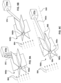
- FIG. 4 shows a first illustrative hydrostatic pressure turbine runner 440 according to an aspect of the present disclosure, for use in a flat-flowing river.
- the hydrostatic pressure turbine runner 440 comprises a rotatable shaft 442 and a plurality of hydrostatic pressure blades 400 carried by and extending radially outwardly from the shaft 442.
- Each of the hydrostatic pressure blades 400 as shown has, relative to the flow direction 404, an upstream face 406 that is substantially planar and a downstream face 408 having an asymmetric convex shape but may have any suitable shape.
- the hydrostatic pressure blades 400 may be mounted directly or indirectly to the shaft 442, which may be hollow or solid, and which may be circular in cross-section, or have any other suitable cross-sectional shape.
- the shaft 442 may form part of, or be mechanically coupled to, a power extraction mechanism (e.g. a generator).
- a power extraction mechanism e.g. a generator
- each hydrostatic pressure blade 400 is mechanically coupled to a power extraction mechanism.
- the hydrostatic pressure blades 400 are circumferentially equally spaced about the shaft 442.
- the hydrostatic pressure turbine runner 440 shown in Figure 4 is a semi-submerged embodiment in which only a lower portion of the hydrostatic pressure turbine runner 440 is immersed below surface 444 of the river 446, with the shaft 442 above the surface 444.
- the hydrostatic pressure turbine runner 440 is immersed to a depth substantially equal to the span A of the hydrostatic pressure blades 400 and supported by mechanical couplings (not shown for simplicity of illustration) extending between the shaft 442 and the hydrostatic pressure blades 400.
- the hydrostatic pressure blades 400 are outwardly radially spaced from the shaft 442.
- the mechanical couplings preferably remain above the surface 444 of the river 446.
- the shaft 442 is positioned with its axis substantially parallel to the flow direction 404. Because the hydrostatic pressure blades 400 are carried by the shaft 442, the hydrostatic pressure blades 400 are limited to movement across, i.e. substantially perpendicular to, the flow direction 404, with movement in other directions (e.g. downstream) being inhibited. At the same time, because the shaft 442 is rotatable, movement of the hydrostatic pressure blades 400 across the flow direction 404 delivers torque 450 to the shaft 442 and results in rotation of the shaft 442 about its axis. The magnitude of the torque 450 is determined by the product of the force F (see Figure 3B ) and the perpendicular distance of the torque vector from the axis of the shaft 442. In the illustrated embodiment the torque 450 is clockwise as shown.
- FIG. 5 shows a segmented hydrostatic pressure turbine runner 540 according to an aspect of the present disclosure.
- the hydrostatic pressure turbine runner 540 shown in Figure 5 is similar to the one shown in Figure 4 in that it comprises a rotatable shaft 542 and a plurality of circumferentially equally spaced hydrostatic pressure blades 500 carried by and extending radially outwardly from the shaft 542.
- the hydrostatic pressure blades 500 each have an upstream face 506 and a downstream face 508 relative to the flow direction 504.
- the upstream face 506 and the downstream face 508 are both shown as planar for ease of illustration but may have any suitable shape.
- the shaft 542 may be part of, or be mechanically coupled to, a power extraction mechanism (e.g.
- segmented hydrostatic pressure turbine runner 540 the hydrostatic pressure blades 500 are arranged in a series of longitudinally spaced segments or modules 548, that is, sets of hydrostatic pressure blades 500 are arranged in longitudinal series on the shaft 542, separated by gaps 552.
- the shaft 542 may be of monolithic construction, or may itself be formed in coupled segments.
- a segmented hydrostatic pressure turbine runner 540 of the type shown in Figure 5 can provide a greater cumulative longitudinal engagement extent while accommodating, for example, geographical features in the river or structural supports for the shaft 542.
- the total longitudinal engagement extent for the segmented hydrostatic pressure turbine runner 540 is the arithmetical sum of all the longitudinal engagement extents of the individual segments 548; the extent of the gaps 552 is not included in the longitudinal engagement extent.
- the hydrostatic pressure turbine runner 540 may be semi-submerged or fully submerged.
- the various segments 548 may be arranged so that the hydrostatic pressure blades 500 of each adjacent segment 548 are offset in their relative radial positions with respect to each other.
- the segments 548 may also differ in the angles of attack for their respective hydrostatic pressure blades 500.
- the performance of the hydrostatic pressure blades 500 of each of the individual segments 548 need not be identical, and the hydrostatic pressure blades 500 of each of the individual segments 548 can be enhanced by applying the various performance enhancements as delineated herein.
- the angle of attack need not be static, but can instead be varied.
- Reference is now made to Figure 6A through 6C show certain illustrative approaches for varying the angle of attack of a hydrostatic pressure blade. Varying the angle of attack may be advantageous to accommodate variations in the flow conditions, for example seasonal variations.
- FIGS. 6B and 6C illustrate an arrangement in which the angle of attack can be varied by twisting the hydrostatic pressure blades 600c.
- the hydrostatic pressure blades 600c are made of flexible material and are attached to the shaft 642 by way of a pair of rigid stellate mounting frames 656 carried by the shaft 642.
- the stellate mounting frames 656 each comprise a plurality of outwardly extending spines 658, and the hydrostatic pressure blades 600c each extend between an opposed pair of the spines 658.
- At least one of the stellate mounting frames 656 is rotatable about the axis of the shaft 642, as shown by arrow 654c. By rotating one of the stellate mounting frames 656 relative to the other, the flexible material forming the hydrostatic pressure blades 600c can be twisted to thereby alter the angle of attack.
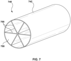
- Figure 7 shows a submerged hydrostatic pressure turbine runner 740 according to an aspect of the present disclosure.
- the rotatable shaft 742 of the hydrostatic pressure turbine runner 740 takes the form of a hollow tube, and a plurality of hydrostatic pressure blades 700 are carried by the shaft 742 and extend inwardly from an inner surface 758 of the tubular shaft 742.
- the shaft 742 entirely encircles the hydrostatic pressure blades 700, and rotates with the hydrostatic pressure blades 700, and liquid can flow through the interior of the shaft 742 past the hydrostatic pressure blades 700.
- the shaft is an interrupted shaft rather than a continuous shaft, with structural integrity provided at least in part by the hydrostatic pressure blades.
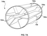
- Figure 7A shows a submerged hydrostatic pressure turbine runner 740a in which the hydrostatic pressure blades 700a are fixed in relative position by a series of spaced-apart rings 759 that rotate with the hydrostatic pressure blades 700a. While Figure 7A shows a pair of rings 759, in other embodiments there may be a larger number of rings.
- the hydrostatic pressure blades 700A shown in Figure 7A are similar in shape to the hydrostatic pressure blades 400 shown in Figure 4 , but may have any suitable shape.
- the external edges 760a of the hydrostatic pressure blades 700a are coupled to the rings 759 and the internal edges 762a of the hydrostatic pressure blades 700a are radially spaced from one another.
- a hydrostatic pressure turbine runner in which the hydrostatic pressure blades extend outwardly from a central shaft may be enclosed by a fixed tube having a diameter slightly larger than the sum of the diameter of the shaft and the span of the hydrostatic pressure blades, creating an annular gap and allowing the hydrostatic pressure turbine runner to rotate inside the fixed tube.
- FIGS 8A to 8F show various modifications to hydrostatic pressure blades according to aspects of the present disclosure, and represent potential optimizations to enhance performance under specific conditions. Although the modifications are shown individually for purposes of illustration, two or more modifications may be incorporated in a single hydrostatic pressure blade. Flow direction is shown by arrows 804.
- Figure 8A shows a hydrostatic pressure turbine runner 840a in which the external edges 860a (those furthest from the central shaft 842a) of the hydrostatic pressure blades 800a are longer than the internal edges 862a (those closest to the shaft 842a) thereof. This results in inclined leading edges 864a.
- Figure 8B shows a similar hydrostatic pressure turbine runner 840b in which the external edges 860b of the hydrostatic pressure blades 800b are longer than the internal edges 862b thereof, but with the leading edges 864b curving concavely outwardly from the central shaft 842b.
- Figure 8C shows a hydrostatic pressure turbine runner 840c in which the external edges 860c of the hydrostatic pressure blades 800c are shorter than the internal edges 862c, also resulting in inclined leading edges 864c, but in the opposite direction to that shown in Figure 8A .
- Figure 8D shows a hydrostatic pressure turbine runner 840d in which the leading edges 864d curve convexly outwardly from the central shaft 842d toward the external edges 860d of the hydrostatic pressure blades 800d.
- the trailing edges 866a, 866b, 866c, 866d remain perpendicular to the shaft 842a, 842b, 842c, 842d.
- the profile of the trailing edge may be altered in a manner similar to that shown for the leading edge, with the same or a different angle or curvature.
- Figure 8E shows a hydrostatic pressure turbine runner 840e in which tapered tubular ailerons 870e are affixed at the external edges 860e of the hydrostatic pressure blades 800e and extend beyond the leading edges 864e and the trailing edges 866e of the hydrostatic pressure blades 800e.
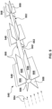
- Figure 8F shows a hydrostatic pressure turbine runner 840f in which the trailing edges 866f and the leading edges 864f of the hydrostatic pressure blades 800f are both substantially perpendicular to the shaft 842f, but with the trailing edges 866f being longer than the leading edges 864f. This results in the straight external edges 860f of the hydrostatic pressure blades 800f being angled rather than substantially parallel to the shaft 842f. This configuration is useful where the hydrostatic pressure turbine runner 840f is immersed into the flow with one end at a higher elevation than the other (see Figure 9C , described below).
- the cords B of the hydrostatic pressure blades can extend 100 meters or more, and the span A may also be substantial.
- the power extraction mechanism e.g. a generator
- the power extraction mechanism can be positioned above the surface.
- the power extraction mechanism can be positioned on a floating barge (e.g. moored to the riverbanks), or attached to fixed supports at the riverbed bottom, or disposed on the riverbank.
- a mechanical device may be used to adjust the elevation of the hydrostatic pressure turbine runner to accommodate seasonal changes in water levels.
- the power generated by rotation of the hydrostatic pressure turbine runner has to be transmitted to the power extraction mechanism.
- the preferred position of the power extraction mechanism is at the downstream side of the hydrostatic pressure turbine runner, but upstream positions of the power extraction mechanism are also contemplated.
- Figures 9A through 9C show some non-limiting examples of transfer arrangements for transmitting power from a hydrostatic pressure turbine runner to a power extraction mechanism such as an electrical generator.
- Figure 9A shows a hydrostatic pressure turbine runner 940a that is coupled to a power extraction mechanism 970a by way of a transfer gearbox 972; a similar arrangement may use a chain or belt transfer case instead of the gearbox 972.
- the gearbox 972 is substantially perpendicular to the shaft 942a of the hydrostatic pressure turbine runner 940a and the flow direction 904a although this is not strictly necessary.
- Figure 9B shows a hydrostatic pressure turbine runner 940b that is coupled to a power extraction mechanism 970b by way of direct transfer through an inclined linked driveshaft 974.
- the power extraction mechanism unit can be positioned directly above the end of the hydrostatic pressure turbine runner.
- Figure 9C shows a hydrostatic pressure turbine runner 940c whose shaft 942c is inclined relative to the water surface 944. Despite this incline, the shaft 942c is kept parallel to the water flow direction 904 as measured in the horizontal plane (i.e. a vertical projection of the shaft 942c onto the water surface 944 is parallel to the flow direction 904).
- the shaft 942c extends well downstream of the hydrostatic pressure blades 900c, and can be coupled directly to the power extraction mechanism 970c located above the water surface 944.
- the hydrostatic pressures blades 900c preferably have a trapezoid form with the trailing edges 966 being longer than the leading edges 964, so that the external edge 960c of the lowermost hydrostatic pressures blade 900c will be substantially parallel to the bottom of the riverbed.
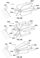
- Figures 9D and 9E each show arrangements for transferring torque from a hydrostatic pressure turbine runner 740a of the type shown in Figure 7A , in which the hydrostatic pressure blades 700a are fixed in relative position by a series of spaced-apart rings 759 that rotate with the hydrostatic pressure blades 700a.
- a downstream one of the rings 759 forms a gear surface 980 that meshes with another gear 982 to transfer torque to a power extraction mechanism.
- a belt 984 is used to transfer torque; a chain could similarly be used.
- a hydrostatic pressure turbine runner may be coupled to a power extraction mechanism apparatus through any suitable torque transmitting device, and accordingly, Figures 9A to 9E show various embodiments of turbines incorporating a hydrostatic pressure turbine runner according to aspects of the present disclosure. Hydraulic transfer of power from a hydrostatic pressure turbine runner to a power extraction mechanism is also contemplated. Accordingly, the term "hydrostatic pressure turbine” refers to a turbine that incorporates a hydrostatic pressure turbine runner adapted for extracting power out of the hydrostatic pressure of a flowing liquid so that a substantial proportion of the total force driving movement of each hydrostatic pressure blade across the flow is contributed by the hydrostatic force.
- hydrostatic pressure turbine runners shown in the Figures described above each have six hydrostatic pressure blades, this is merely illustrative and a hydrostatic pressure turbine runner according to the present disclosure may have more or fewer hydrostatic pressure blades, depending on the installation.
- the number of blades will be influenced by design parameters such as the available space to accommodate the span of the hydrostatic pressure blades and the speed of the fluid flow.
- Figure 10 shows an autonomous submerged hydrostatic pressure turbine 1080 in which the power extraction mechanism 1070 is disposed within the shaft 1042 of the hydrostatic pressure turbine runner 1040.
- the flow direction is shown by arrows 1004.
- the shaft 1042 is enlarged to accommodate the power extraction mechanism 1070, with streamlined end caps 1082 (e.g. conical or similar).
- the end caps 1082 may be fixed to supports, for example on the riverbed, depending from a barge, etc.
- the shaft 1042 can rotate relative to the end caps 1082, and the power extraction mechanism 1070 comprises a stator disposed within the shaft 1042, which functions as a rotor. This arrangement can, with suitable engineering modifications, be reversed. Electrical cabling can then connect the power extraction mechanism 1070 to, for example, an electrical grid.
- the three hydrostatic pressure blades 1000 of the hydrostatic pressure turbine runner 1040 include ailerons 1084 at their external edges 1060 to limit hydrostatic pressure leaks between the upstream side 1006 and the downstream side 1008 of the hydrostatic pressure blades 1000.
- the ailerons may have various shapes and forms, depending on the conditions.
- the power extraction mechanism may be coupled directly to the end of the hydrostatic pressure turbine runner, rather than being incorporated into the shaft.
- the power extraction mechanism may be fixed above the flow surface or submerged below the flow surface.
Landscapes
- Engineering & Computer Science (AREA)
- Chemical & Material Sciences (AREA)
- Combustion & Propulsion (AREA)
- Mechanical Engineering (AREA)
- General Engineering & Computer Science (AREA)
- Power Engineering (AREA)
- Hydraulic Turbines (AREA)
- Other Liquid Machine Or Engine Such As Wave Power Use (AREA)
- Turbine Rotor Nozzle Sealing (AREA)
Applications Claiming Priority (2)
| Application Number | Priority Date | Filing Date | Title |
|---|---|---|---|
| US16/662,632 US10738755B1 (en) | 2019-10-24 | 2019-10-24 | Hydrostatic pressure turbines and turbine runners therefor |
| PCT/CA2020/050974 WO2021077203A1 (en) | 2019-10-24 | 2020-07-13 | Hydrostatic pressure turbines and turbine runners therefor |
Publications (4)
| Publication Number | Publication Date |
|---|---|
| EP4028661A1 EP4028661A1 (en) | 2022-07-20 |
| EP4028661A4 EP4028661A4 (en) | 2023-10-04 |
| EP4028661B1 true EP4028661B1 (en) | 2025-06-11 |
| EP4028661C0 EP4028661C0 (en) | 2025-06-11 |
Family
ID=71994173
Family Applications (1)
| Application Number | Title | Priority Date | Filing Date |
|---|---|---|---|
| EP20878901.6A Active EP4028661B1 (en) | 2019-10-24 | 2020-07-13 | Hydrostatic pressure turbines and turbine runners therefor |
Country Status (16)
| Country | Link |
|---|---|
| US (1) | US10738755B1 (https=) |
| EP (1) | EP4028661B1 (https=) |
| JP (1) | JP2022553340A (https=) |
| KR (1) | KR20220084378A (https=) |
| CN (1) | CN114599875A (https=) |
| AR (1) | AR119431A1 (https=) |
| AU (1) | AU2020369157B2 (https=) |
| BR (1) | BR112022007628A2 (https=) |
| CA (1) | CA3096958C (https=) |
| CL (1) | CL2022000982A1 (https=) |
| GB (1) | GB2588519C (https=) |
| HU (1) | HUE072517T2 (https=) |
| MX (1) | MX2022004746A (https=) |
| PY (1) | PY2034191A (https=) |
| UY (1) | UY38780A (https=) |
| WO (1) | WO2021077203A1 (https=) |
Families Citing this family (1)
| Publication number | Priority date | Publication date | Assignee | Title |
|---|---|---|---|---|
| WO2025210688A1 (en) * | 2024-04-04 | 2025-10-09 | Fustinoni Alessandro | Rotor for hydrokinetic turbine and respective hydrokinetic turbine |
Family Cites Families (21)
| Publication number | Priority date | Publication date | Assignee | Title |
|---|---|---|---|---|
| US587814A (en) * | 1897-08-10 | Current water-motor | ||
| US3209156A (en) * | 1962-04-03 | 1965-09-28 | Jr Arthur D Struble | Underwater generator |
| GB9407695D0 (en) * | 1994-04-19 | 1994-06-15 | Burns David J | Electrical power generating apparatus and an electrical vehicle including such apparatus |
| JP4458641B2 (ja) * | 1999-08-20 | 2010-04-28 | 株式会社東芝 | 軸流水車発電装置 |
| PT1415087E (pt) * | 2001-07-11 | 2005-08-31 | Hydra Tidal Energy Technology | Instalacao para geracao de energia a partir de correntes aquaticas |
| DE10256864B4 (de) * | 2002-12-05 | 2007-09-06 | Ernst Buttler | Wasserkraftanlage |
| WO2008016584A2 (en) * | 2006-08-01 | 2008-02-07 | Ghosh Dwipen N | Wind turbine |
| US20080159873A1 (en) * | 2006-12-05 | 2008-07-03 | Neo-Aerodynamic Ltd. | Cross fluid-flow axis turbine |
| US7918646B2 (en) * | 2007-01-22 | 2011-04-05 | Lonestar Inventions LLP | High efficiency turbine with variable attack angle foils |
| US20090250937A1 (en) * | 2008-04-07 | 2009-10-08 | Stuart Manuel I | Relative wind vortex rotary turbine alternating current device (RWVT) |
| CA2631204A1 (en) * | 2008-04-29 | 2009-10-29 | Anthony Duggleby | Surface piercing tidal generator |
| GB2466478A (en) * | 2008-12-02 | 2010-06-30 | Aerovortex Mills Ltd | Suction generation device |
| TWM366607U (en) * | 2009-05-22 | 2009-10-11 | Jetpo Technology Inc | River power hydraulic generator |
| WO2011037471A1 (en) * | 2009-09-23 | 2011-03-31 | Engervik Technology As | Converting kinetic energy using a hydrofoil |
| US20160251964A1 (en) * | 2009-10-26 | 2016-09-01 | Luis Indefonso Solorzano | Apparatus and methods for energy conversion |
| CA2796432A1 (en) * | 2010-05-07 | 2011-11-10 | Flodesign Wind Turbine Corp. | Fluid turbine with moveable fluid control member |
| GB2487404A (en) * | 2011-01-20 | 2012-07-25 | Sea Lix As | Rotor for extracting energy from bidirectional fluid flows |
| WO2012100128A2 (en) * | 2011-01-21 | 2012-07-26 | Anagnou Mars C | Hydroelectric power generating system |
| US20120306205A1 (en) * | 2011-06-06 | 2012-12-06 | Lucid Energy, Inc. | Novel systems for increasing efficiency and power output of in-conduit hydroelectric power system and turbine |
| DE102011105169A1 (de) * | 2011-06-17 | 2012-12-20 | Robert Bosch Gmbh | Verfahren zum Betreiben eines Wellenenergiekonverters und Wellenenergiekonverter |
| GB2543566A (en) * | 2015-10-23 | 2017-04-26 | Sea-Lix As | Rotor apparatus |
-
2019
- 2019-10-24 US US16/662,632 patent/US10738755B1/en active Active
-
2020
- 2020-07-09 PY PY202002034191A patent/PY2034191A/es unknown
- 2020-07-13 EP EP20878901.6A patent/EP4028661B1/en active Active
- 2020-07-13 MX MX2022004746A patent/MX2022004746A/es unknown
- 2020-07-13 HU HUE20878901A patent/HUE072517T2/hu unknown
- 2020-07-13 AU AU2020369157A patent/AU2020369157B2/en active Active
- 2020-07-13 JP JP2022523611A patent/JP2022553340A/ja active Pending
- 2020-07-13 CN CN202080074256.0A patent/CN114599875A/zh active Pending
- 2020-07-13 KR KR1020227016794A patent/KR20220084378A/ko not_active Ceased
- 2020-07-13 UY UY0001038780A patent/UY38780A/es active IP Right Grant
- 2020-07-13 BR BR112022007628A patent/BR112022007628A2/pt active Search and Examination
- 2020-07-13 WO PCT/CA2020/050974 patent/WO2021077203A1/en not_active Ceased
- 2020-07-17 AR ARP200102020A patent/AR119431A1/es active IP Right Grant
- 2020-09-28 GB GB2015343.3A patent/GB2588519C/en active Active
- 2020-10-23 CA CA3096958A patent/CA3096958C/en active Active
-
2022
- 2022-04-19 CL CL2022000982A patent/CL2022000982A1/es unknown
Also Published As
| Publication number | Publication date |
|---|---|
| EP4028661A1 (en) | 2022-07-20 |
| WO2021077203A1 (en) | 2021-04-29 |
| CA3096958C (en) | 2021-05-25 |
| HUE072517T2 (hu) | 2025-11-28 |
| KR20220084378A (ko) | 2022-06-21 |
| CL2022000982A1 (es) | 2022-11-18 |
| MX2022004746A (es) | 2022-08-18 |
| GB2588519A (en) | 2021-04-28 |
| GB2588519B (en) | 2022-03-30 |
| AR119431A1 (es) | 2021-12-15 |
| BR112022007628A2 (pt) | 2022-07-12 |
| AU2020369157A1 (en) | 2023-06-08 |
| JP2022553340A (ja) | 2022-12-22 |
| AU2020369157B2 (en) | 2025-08-21 |
| EP4028661C0 (en) | 2025-06-11 |
| GB2588519C (en) | 2023-03-15 |
| PY2034191A (es) | 2021-07-26 |
| CA3096958A1 (en) | 2021-02-02 |
| GB202015343D0 (en) | 2020-11-11 |
| CN114599875A (zh) | 2022-06-07 |
| US10738755B1 (en) | 2020-08-11 |
| UY38780A (es) | 2021-05-31 |
| EP4028661A4 (en) | 2023-10-04 |
Similar Documents
| Publication | Publication Date | Title |
|---|---|---|
| JP4024208B2 (ja) | 水中用ダクテッドタービン | |
| US8698331B2 (en) | Bidirectional axial flow turbine with self-pivoting blades for use in wave energy converter | |
| RU2461731C2 (ru) | Гидротурбина | |
| US5548956A (en) | Cable restrained reciprocating blade system for energy extraction from moving body of water | |
| US20090194997A1 (en) | Darrieus water wheel turbine | |
| EP3258097B1 (en) | Hydroelectric power generator using ebb and flow of seawater | |
| CA2599120C (en) | Device for maintaining a hydraulic turbomachine | |
| GB2452484A (en) | Swinging flap type turbine with Savonius turbine for stall prevention | |
| EP4028661B1 (en) | Hydrostatic pressure turbines and turbine runners therefor | |
| US20100013228A1 (en) | Surface piercing tidal generator | |
| JP5877395B2 (ja) | 水力発電装置 | |
| JP2002310054A (ja) | 潮流発電装置 | |
| CN107304745B (zh) | 潮流能发电装置及其导流罩 | |
| JP2002202042A (ja) | 水力装置 | |
| RU2171912C2 (ru) | Бесплотинная всесезонная гидроэлектростанция | |
| RU2227227C2 (ru) | Бесплотинная всесезонная гидроэлектростанция | |
| JPWO2021077203A5 (https=) | ||
| CA2532734A1 (en) | Economic low-head hydro and tidal power turbine | |
| KR102857731B1 (ko) | 조류발전용 다단 나선형 돛 가변익 터빈 | |
| WO2006033598A1 (en) | Dam-less tractive power plant | |
| WO2024110893A1 (en) | Hydro-turbine and its deployment | |
| JPS62168970A (ja) | 水流の運動エネルギ−を利用した動力発生装置 | |
| GB2549283A (en) | Ocean wave kinetic energy conversion method and system | |
| EP3332116A1 (de) | Schaufelradvorrichtung, schaufelradmodul und strömungskraftwerk | |
| BG109645A (bg) | Безнапорна водна турбина |
Legal Events
| Date | Code | Title | Description |
|---|---|---|---|
| STAA | Information on the status of an ep patent application or granted ep patent |
Free format text: STATUS: THE INTERNATIONAL PUBLICATION HAS BEEN MADE |
|
| PUAI | Public reference made under article 153(3) epc to a published international application that has entered the european phase |
Free format text: ORIGINAL CODE: 0009012 |
|
| STAA | Information on the status of an ep patent application or granted ep patent |
Free format text: STATUS: REQUEST FOR EXAMINATION WAS MADE |
|
| 17P | Request for examination filed |
Effective date: 20220412 |
|
| AK | Designated contracting states |
Kind code of ref document: A1 Designated state(s): AL AT BE BG CH CY CZ DE DK EE ES FI FR GB GR HR HU IE IS IT LI LT LU LV MC MK MT NL NO PL PT RO RS SE SI SK SM TR |
|
| DAV | Request for validation of the european patent (deleted) | ||
| DAX | Request for extension of the european patent (deleted) | ||
| A4 | Supplementary search report drawn up and despatched |
Effective date: 20230901 |
|
| RIC1 | Information provided on ipc code assigned before grant |
Ipc: F03B 17/06 20060101ALI20230828BHEP Ipc: F03B 13/10 20060101ALI20230828BHEP Ipc: F03B 3/04 20060101AFI20230828BHEP |
|
| GRAP | Despatch of communication of intention to grant a patent |
Free format text: ORIGINAL CODE: EPIDOSNIGR1 |
|
| STAA | Information on the status of an ep patent application or granted ep patent |
Free format text: STATUS: GRANT OF PATENT IS INTENDED |
|
| INTG | Intention to grant announced |
Effective date: 20250107 |
|
| GRAS | Grant fee paid |
Free format text: ORIGINAL CODE: EPIDOSNIGR3 |
|
| GRAA | (expected) grant |
Free format text: ORIGINAL CODE: 0009210 |
|
| STAA | Information on the status of an ep patent application or granted ep patent |
Free format text: STATUS: THE PATENT HAS BEEN GRANTED |
|
| AK | Designated contracting states |
Kind code of ref document: B1 Designated state(s): AL AT BE BG CH CY CZ DE DK EE ES FI FR GR HR HU IE IS IT LI LT LU LV MC MK MT NL NO PL PT RO RS SE SI SK SM TR |
|
| RAP3 | Party data changed (applicant data changed or rights of an application transferred) |
Owner name: ADCANIN INC. |
|
| RBV | Designated contracting states (corrected) |
Designated state(s): AL AT BE BG CH CY CZ DE DK EE ES FI FR GR HR HU IE IS IT LI LT LU LV MC MK MT NL NO PL PT RO RS SE SI SK SM TR |
|
| REG | Reference to a national code |
Ref country code: CH Ref legal event code: EP |
|
| REG | Reference to a national code |
Ref country code: IE Ref legal event code: FG4D |
|
| REG | Reference to a national code |
Ref country code: DE Ref legal event code: R096 Ref document number: 602020052747 Country of ref document: DE |
|
| U01 | Request for unitary effect filed |
Effective date: 20250709 |
|
| U07 | Unitary effect registered |
Designated state(s): AT BE BG DE DK EE FI FR IT LT LU LV MT NL PT RO SE SI Effective date: 20250715 |
|
| U20 | Renewal fee for the european patent with unitary effect paid |
Year of fee payment: 6 Effective date: 20250722 |
|
| PG25 | Lapsed in a contracting state [announced via postgrant information from national office to epo] |
Ref country code: ES Free format text: LAPSE BECAUSE OF FAILURE TO SUBMIT A TRANSLATION OF THE DESCRIPTION OR TO PAY THE FEE WITHIN THE PRESCRIBED TIME-LIMIT Effective date: 20250611 |
|
| PG25 | Lapsed in a contracting state [announced via postgrant information from national office to epo] |
Ref country code: NO Free format text: LAPSE BECAUSE OF FAILURE TO SUBMIT A TRANSLATION OF THE DESCRIPTION OR TO PAY THE FEE WITHIN THE PRESCRIBED TIME-LIMIT Effective date: 20250911 Ref country code: GR Free format text: LAPSE BECAUSE OF FAILURE TO SUBMIT A TRANSLATION OF THE DESCRIPTION OR TO PAY THE FEE WITHIN THE PRESCRIBED TIME-LIMIT Effective date: 20250912 |
|
| PGFP | Annual fee paid to national office [announced via postgrant information from national office to epo] |
Ref country code: HU Payment date: 20250829 Year of fee payment: 6 |
|
| PG25 | Lapsed in a contracting state [announced via postgrant information from national office to epo] |
Ref country code: HR Free format text: LAPSE BECAUSE OF FAILURE TO SUBMIT A TRANSLATION OF THE DESCRIPTION OR TO PAY THE FEE WITHIN THE PRESCRIBED TIME-LIMIT Effective date: 20250611 |
|
| PGFP | Annual fee paid to national office [announced via postgrant information from national office to epo] |
Ref country code: CH Payment date: 20250818 Year of fee payment: 6 |
|
| PG25 | Lapsed in a contracting state [announced via postgrant information from national office to epo] |
Ref country code: RS Free format text: LAPSE BECAUSE OF FAILURE TO SUBMIT A TRANSLATION OF THE DESCRIPTION OR TO PAY THE FEE WITHIN THE PRESCRIBED TIME-LIMIT Effective date: 20250911 |
|
| REG | Reference to a national code |
Ref country code: HU Ref legal event code: AG4A Ref document number: E072517 Country of ref document: HU |
|
| PG25 | Lapsed in a contracting state [announced via postgrant information from national office to epo] |
Ref country code: IS Free format text: LAPSE BECAUSE OF FAILURE TO SUBMIT A TRANSLATION OF THE DESCRIPTION OR TO PAY THE FEE WITHIN THE PRESCRIBED TIME-LIMIT Effective date: 20251011 |
|
| PG25 | Lapsed in a contracting state [announced via postgrant information from national office to epo] |
Ref country code: SM Free format text: LAPSE BECAUSE OF FAILURE TO SUBMIT A TRANSLATION OF THE DESCRIPTION OR TO PAY THE FEE WITHIN THE PRESCRIBED TIME-LIMIT Effective date: 20250611 |
|
| PG25 | Lapsed in a contracting state [announced via postgrant information from national office to epo] |
Ref country code: CZ Free format text: LAPSE BECAUSE OF FAILURE TO SUBMIT A TRANSLATION OF THE DESCRIPTION OR TO PAY THE FEE WITHIN THE PRESCRIBED TIME-LIMIT Effective date: 20250611 |
|
| PG25 | Lapsed in a contracting state [announced via postgrant information from national office to epo] |
Ref country code: PL Free format text: LAPSE BECAUSE OF FAILURE TO SUBMIT A TRANSLATION OF THE DESCRIPTION OR TO PAY THE FEE WITHIN THE PRESCRIBED TIME-LIMIT Effective date: 20250611 |
|
| PG25 | Lapsed in a contracting state [announced via postgrant information from national office to epo] |
Ref country code: SK Free format text: LAPSE BECAUSE OF FAILURE TO SUBMIT A TRANSLATION OF THE DESCRIPTION OR TO PAY THE FEE WITHIN THE PRESCRIBED TIME-LIMIT Effective date: 20250611 |
|
| PG25 | Lapsed in a contracting state [announced via postgrant information from national office to epo] |
Ref country code: MC Free format text: LAPSE BECAUSE OF FAILURE TO SUBMIT A TRANSLATION OF THE DESCRIPTION OR TO PAY THE FEE WITHIN THE PRESCRIBED TIME-LIMIT Effective date: 20250611 |
|
| PLBE | No opposition filed within time limit |
Free format text: ORIGINAL CODE: 0009261 |
|
| STAA | Information on the status of an ep patent application or granted ep patent |
Free format text: STATUS: NO OPPOSITION FILED WITHIN TIME LIMIT |
|
| REG | Reference to a national code |
Ref country code: CH Ref legal event code: L10 Free format text: ST27 STATUS EVENT CODE: U-0-0-L10-L00 (AS PROVIDED BY THE NATIONAL OFFICE) Effective date: 20260423 |