EP4028623B1 - Vorrichtung und verfahren zum extrudieren und anwenden von abstandhalterprofilen aus einem isolierglas - Google Patents
Vorrichtung und verfahren zum extrudieren und anwenden von abstandhalterprofilen aus einem isolierglas Download PDFInfo
- Publication number
- EP4028623B1 EP4028623B1 EP20786596.5A EP20786596A EP4028623B1 EP 4028623 B1 EP4028623 B1 EP 4028623B1 EP 20786596 A EP20786596 A EP 20786596A EP 4028623 B1 EP4028623 B1 EP 4028623B1
- Authority
- EP
- European Patent Office
- Prior art keywords
- glass
- glass pane
- spacer
- extrusion
- spacer profile
- Prior art date
- Legal status (The legal status is an assumption and is not a legal conclusion. Google has not performed a legal analysis and makes no representation as to the accuracy of the status listed.)
- Active
Links
Images







Classifications
-
- E—FIXED CONSTRUCTIONS
- E06—DOORS, WINDOWS, SHUTTERS, OR ROLLER BLINDS IN GENERAL; LADDERS
- E06B—FIXED OR MOVABLE CLOSURES FOR OPENINGS IN BUILDINGS, VEHICLES, FENCES OR LIKE ENCLOSURES IN GENERAL, e.g. DOORS, WINDOWS, BLINDS, GATES
- E06B3/00—Window sashes, door leaves, or like elements for closing wall or like openings; Layout of fixed or moving closures, e.g. windows in wall or like openings; Features of rigidly-mounted outer frames relating to the mounting of wing frames
- E06B3/66—Units comprising two or more parallel glass or like panes permanently secured together
- E06B3/673—Assembling the units
- E06B3/67326—Assembling spacer elements with the panes
- E06B3/6733—Assembling spacer elements with the panes by applying, e.g. extruding, a ribbon of hardenable material on or between the panes
-
- B—PERFORMING OPERATIONS; TRANSPORTING
- B29—WORKING OF PLASTICS; WORKING OF SUBSTANCES IN A PLASTIC STATE IN GENERAL
- B29C—SHAPING OR JOINING OF PLASTICS; SHAPING OF MATERIAL IN A PLASTIC STATE, NOT OTHERWISE PROVIDED FOR; AFTER-TREATMENT OF THE SHAPED PRODUCTS, e.g. REPAIRING
- B29C48/00—Extrusion moulding, i.e. expressing the moulding material through a die or nozzle which imparts the desired form; Apparatus therefor
- B29C48/15—Extrusion moulding, i.e. expressing the moulding material through a die or nozzle which imparts the desired form; Apparatus therefor incorporating preformed parts or layers, e.g. extrusion moulding around inserts
- B29C48/154—Coating solid articles, i.e. non-hollow articles
- B29C48/155—Partial coating thereof
-
- B—PERFORMING OPERATIONS; TRANSPORTING
- B29—WORKING OF PLASTICS; WORKING OF SUBSTANCES IN A PLASTIC STATE IN GENERAL
- B29C—SHAPING OR JOINING OF PLASTICS; SHAPING OF MATERIAL IN A PLASTIC STATE, NOT OTHERWISE PROVIDED FOR; AFTER-TREATMENT OF THE SHAPED PRODUCTS, e.g. REPAIRING
- B29C48/00—Extrusion moulding, i.e. expressing the moulding material through a die or nozzle which imparts the desired form; Apparatus therefor
- B29C48/25—Component parts, details or accessories; Auxiliary operations
- B29C48/252—Drive or actuation means; Transmission means; Screw supporting means
-
- B—PERFORMING OPERATIONS; TRANSPORTING
- B29—WORKING OF PLASTICS; WORKING OF SUBSTANCES IN A PLASTIC STATE IN GENERAL
- B29C—SHAPING OR JOINING OF PLASTICS; SHAPING OF MATERIAL IN A PLASTIC STATE, NOT OTHERWISE PROVIDED FOR; AFTER-TREATMENT OF THE SHAPED PRODUCTS, e.g. REPAIRING
- B29C48/00—Extrusion moulding, i.e. expressing the moulding material through a die or nozzle which imparts the desired form; Apparatus therefor
- B29C48/25—Component parts, details or accessories; Auxiliary operations
- B29C48/92—Measuring, controlling or regulating
-
- E—FIXED CONSTRUCTIONS
- E06—DOORS, WINDOWS, SHUTTERS, OR ROLLER BLINDS IN GENERAL; LADDERS
- E06B—FIXED OR MOVABLE CLOSURES FOR OPENINGS IN BUILDINGS, VEHICLES, FENCES OR LIKE ENCLOSURES IN GENERAL, e.g. DOORS, WINDOWS, BLINDS, GATES
- E06B3/00—Window sashes, door leaves, or like elements for closing wall or like openings; Layout of fixed or moving closures, e.g. windows in wall or like openings; Features of rigidly-mounted outer frames relating to the mounting of wing frames
- E06B3/66—Units comprising two or more parallel glass or like panes permanently secured together
- E06B3/663—Elements for spacing panes
- E06B3/66309—Section members positioned at the edges of the glazing unit
- E06B3/66328—Section members positioned at the edges of the glazing unit of rubber, plastics or similar materials
-
- B—PERFORMING OPERATIONS; TRANSPORTING
- B29—WORKING OF PLASTICS; WORKING OF SUBSTANCES IN A PLASTIC STATE IN GENERAL
- B29C—SHAPING OR JOINING OF PLASTICS; SHAPING OF MATERIAL IN A PLASTIC STATE, NOT OTHERWISE PROVIDED FOR; AFTER-TREATMENT OF THE SHAPED PRODUCTS, e.g. REPAIRING
- B29C2948/00—Indexing scheme relating to extrusion moulding
- B29C2948/92—Measuring, controlling or regulating
- B29C2948/92009—Measured parameter
- B29C2948/92076—Position, e.g. linear or angular
-
- B—PERFORMING OPERATIONS; TRANSPORTING
- B29—WORKING OF PLASTICS; WORKING OF SUBSTANCES IN A PLASTIC STATE IN GENERAL
- B29C—SHAPING OR JOINING OF PLASTICS; SHAPING OF MATERIAL IN A PLASTIC STATE, NOT OTHERWISE PROVIDED FOR; AFTER-TREATMENT OF THE SHAPED PRODUCTS, e.g. REPAIRING
- B29C2948/00—Indexing scheme relating to extrusion moulding
- B29C2948/92—Measuring, controlling or regulating
- B29C2948/92323—Location or phase of measurement
- B29C2948/92352—Inserts
-
- B—PERFORMING OPERATIONS; TRANSPORTING
- B29—WORKING OF PLASTICS; WORKING OF SUBSTANCES IN A PLASTIC STATE IN GENERAL
- B29C—SHAPING OR JOINING OF PLASTICS; SHAPING OF MATERIAL IN A PLASTIC STATE, NOT OTHERWISE PROVIDED FOR; AFTER-TREATMENT OF THE SHAPED PRODUCTS, e.g. REPAIRING
- B29C2948/00—Indexing scheme relating to extrusion moulding
- B29C2948/92—Measuring, controlling or regulating
- B29C2948/92504—Controlled parameter
- B29C2948/92571—Position, e.g. linear or angular
-
- B—PERFORMING OPERATIONS; TRANSPORTING
- B29—WORKING OF PLASTICS; WORKING OF SUBSTANCES IN A PLASTIC STATE IN GENERAL
- B29C—SHAPING OR JOINING OF PLASTICS; SHAPING OF MATERIAL IN A PLASTIC STATE, NOT OTHERWISE PROVIDED FOR; AFTER-TREATMENT OF THE SHAPED PRODUCTS, e.g. REPAIRING
- B29C2948/00—Indexing scheme relating to extrusion moulding
- B29C2948/92—Measuring, controlling or regulating
- B29C2948/92819—Location or phase of control
- B29C2948/92857—Extrusion unit
-
- B—PERFORMING OPERATIONS; TRANSPORTING
- B29—WORKING OF PLASTICS; WORKING OF SUBSTANCES IN A PLASTIC STATE IN GENERAL
- B29K—INDEXING SCHEME ASSOCIATED WITH SUBCLASSES B29B, B29C OR B29D, RELATING TO MOULDING MATERIALS OR TO MATERIALS FOR MOULDS, REINFORCEMENTS, FILLERS OR PREFORMED PARTS, e.g. INSERTS
- B29K2105/00—Condition, form or state of moulded material or of the material to be shaped
- B29K2105/04—Condition, form or state of moulded material or of the material to be shaped cellular or porous
-
- B—PERFORMING OPERATIONS; TRANSPORTING
- B29—WORKING OF PLASTICS; WORKING OF SUBSTANCES IN A PLASTIC STATE IN GENERAL
- B29K—INDEXING SCHEME ASSOCIATED WITH SUBCLASSES B29B, B29C OR B29D, RELATING TO MOULDING MATERIALS OR TO MATERIALS FOR MOULDS, REINFORCEMENTS, FILLERS OR PREFORMED PARTS, e.g. INSERTS
- B29K2709/00—Use of inorganic materials not provided for in groups B29K2703/00 - B29K2707/00, for preformed parts, e.g. for inserts
- B29K2709/08—Glass
-
- B—PERFORMING OPERATIONS; TRANSPORTING
- B29—WORKING OF PLASTICS; WORKING OF SUBSTANCES IN A PLASTIC STATE IN GENERAL
- B29K—INDEXING SCHEME ASSOCIATED WITH SUBCLASSES B29B, B29C OR B29D, RELATING TO MOULDING MATERIALS OR TO MATERIALS FOR MOULDS, REINFORCEMENTS, FILLERS OR PREFORMED PARTS, e.g. INSERTS
- B29K2995/00—Properties of moulding materials, reinforcements, fillers, preformed parts or moulds
- B29K2995/0012—Properties of moulding materials, reinforcements, fillers, preformed parts or moulds having particular thermal properties
- B29K2995/0015—Insulating
-
- B—PERFORMING OPERATIONS; TRANSPORTING
- B29—WORKING OF PLASTICS; WORKING OF SUBSTANCES IN A PLASTIC STATE IN GENERAL
- B29L—INDEXING SCHEME ASSOCIATED WITH SUBCLASS B29C, RELATING TO PARTICULAR ARTICLES
- B29L2031/00—Other particular articles
- B29L2031/001—Profiled members, e.g. beams, sections
Definitions
- the present finding relates to a device and a procedure for the extrusion and application of a spacer profile of insulating glass, particularly for a machine adapted to compose the spacer frame directly against one or more glass panes constituting the insulating glass starting from a thermoplastic product prevalently contained in drums, displacing the extrados thereof to an adjustable and controlled distance referred to the margin of one or more glass panes.
- the operation may also be multiple to obtain insulating glass 1 constituted by three glass panes 2, 2', 2'' and two frames 3, 3' or spacer profiles 5, 5', as well as "n” glass panes 2, 2', 2", 2′′′, etc., 2M, 2'm, 2"m, etc. and "n-1" frames or spacer profiles 3, 3', 3", etc., 5, 5', 5'', etc. (hereinafter, for ease of reading, the adverb etc. will be implied even if it is not written, and sometimes we will write generically glass pane 2, spacer profile 3, 5, 7, meaning the entire families or more simply glass pane, glass panes, spacer frame, spacer frames).
- thermoplastic product more effective if of the reactive type, i.e. partially transformed into elastomeric by reaction with air humidity, against the face of one or more of the two or more glass panes to constitute a profile 7, 7', 7", etc. and then the spacer frame for the successive composition of the insulating glass.
- the section of such profile is rectangular but sections having different shapes, e.g. with slightly convex extrados (orientation referred to the insulating glass chamber), can also be processed.
- the invention which is the object of the present application is of essential relevance in its multiple implementations, particularly when the real geometry of the glass panes differs, albeit slightly, from the theoretical geometry, a fact which occurs both accidentally and systematically. Furthermore, the invention also compensates for all the disturbances originated by the handling devices, meaning that it makes the positioning of the spacer profile 7, 7', 7" constantly referred to the margin of the glass panes although the panes themselves undergo jerking movements by the effect of the irregularities of the conveyors. Moreover, the main inventive concept illustrated below can also be applied to the type of profile 5, 5', 5'' and, therefore, of spacer frame made of elastic and flexible synthetic material, supplied in coils.
- the insulating glass 1 is constituted by the composition of two or more glass panes 2, 2', 2", 2′′′, 2M, 2'm, 2"m, separated by one or more spacer frames 3, 3', 3", generally made of inorganic material, e.g.
- the spacer frames 3, 3', 3" containing hygroscopic material 4 in their hollow part and being provided with a butyl sealant 6 on the side faces (constituting the so-called first sealing) and the chamber (or chambers), delimited by the glass panes 2, 2', 2", 2′′′, 2M, 2'm, 2"m and the frame spacer (or frame spacers) 3', 3'', 3'', being able to contain, for example, air or gas 8 or gas mixtures 8 conferring particular properties, e.g. heat insulating and/or sound insulating properties, to the insulating glass.
- PVC polyvinyl chloride
- compositions are obtained by using a flexible spacer frame 5, 5', 5'' having essentially rectangular section, possibly containing two receptacles on its sides for butyl sealant 6, made of foamed synthetic organic material, e.g. such as silicone or EPDM (EthylenePropylene Diene Monomer) and bearing in its sides or part thereof an adhesive 6' useful for mechanically bonding to the glass panes, or employing an extruded spacer profile 7', 7', 7", also having essentially rectangular cross-section made of thermoplastic material, and it is the latter that is dealt with particularly in the present invention; in such cases, the hygroscopic material 4 is distributed in the mass of the spacer profile itself because it is already contained in the compound which generates such profiles.
- foamed synthetic organic material e.g. such as silicone or EPDM (EthylenePropylene Diene Monomer)
- an adhesive 6' useful for mechanically bonding to the glass panes
- glass panes 2, 2', 2", 2′′′, 2M, 2'm, 2''m and spacer frame or spacer frames 3, 3', 3'' or 5, 5', 5'' or 7, 7', 7'' is obtained by means of two levels of sealing, the first 6 (also named “primary” in the industry), having the function of hermetically sealing and initially bonding such components and concerning the side surfaces of the frame and the portions of the adjacent glass panes, mentioned above (thermoplastic butyl sealant for the spacer frame conformations if of types 3 and 5, or constituted by the spacer frame itself if of type 7 made of thermoplastic material as is the case of the present invention), the second 9 (also named “secondary” in the industry), typically constituted by a two-component, elastomeric sealant, such as polysulphide (PS) or polyurethane (PU) or silicone (SI), processed at ambient temperature, but also constituted by a single-component sealant of the type processed at ambient temperature or hot-processe
- the first sealing level is replaced by (in this case, not retaining the sealing function) or may be integrated with (in this case, retaining the sealing function) an adhesive 6', e.g. acrylic, previously sprinkled on the side faces of the spacer profile itself and coated with a removable protective film (see Fig. 1D in which such film is shown already removed).
- an adhesive 6' e.g. acrylic
- the glass panes 2, 2', 2", 2′′′, 2M, 2'm, 2''m used in the composition of the insulating glass 1 may have different conformations according to the use thereof, e.g. the outer glass (i.e. outer with respect to the building) can be normal or reflective or selective (to limit heat input during the summer months) or laminated/armored (for anti-intrusion/vandalism/bulletproof functions) or laminated/tempered (for safety functions) or combined (e.g. reflective and laminated to achieve a combination of properties), the inner glass (i.e. inner with respect to the building) can be normal or low emissivity (to limit heat loss during the winter months) or laminated/tempered (for safety functions) or combined (e.g. low emissivity and laminated to achieve a combination of properties).
- the outer glass i.e. outer with respect to the building
- the inner glass i.e. inner with respect to the building
- the inner glass i.e. inner with respect to the building
- a manufacturing line for obtaining the insulating glass product 1 requires many processes in cascade, and in particular comprises the one concerning the formation of the spacer frame, whether of the "extruded thermoplastic” type or the “flexible foamed synthetic” type, to both of which the present application provides an improving contribution.
- the relative movement between glass pane 2, 2', 2", 2′′′ and extrusion nozzle 301 is achieved through mechatronic mechanisms driven by synchronous motors respectively according to mutually interlaced axes H, V, ⁇ , while at least one further axis K, also driven by a synchronous motor, governs the delivery of the molten compound in interaction with the aforesaid axes.
- Another transverse axis Z concerns the adjustment of the position of the nozzle 301 to adapt to the thickness of the glass panes but, in the prior art, this is not controlled as a process function.
- the geometry of the glass panes is not equally precise, either along the two main directions according to the x, y axes by the effect of the inaccuracy of the cutting process of the glass panes themselves (x and y of the glass panes corresponding respectively to synchronous H and V of the machine), or according to the z axis due to the non-planarity of the glass panes (z corresponding to Z, which is non-synchronous and only with position feedback, of the machine, at least in the described known art).
- Such constancy of depth guaranteeing the functions of the secondary sealant of: structural bonding of the glass pane / spacer frame components; hermetic sealing against the penetration of moisture from the outside to the inside of the insulating glass; hermetic sealing against the escape of pressure-regulating gas from the inside to the outside of the insulating glass, which gas tends to migrate to areas lacking secondary sealant being subject to Dalton's law of partial pressures.
- An object which is not less important but a necessary complement of the illustrated task, to control the approaching force of the extrusion nozzle against the face of the glass pane.
- the invention provides devices according to claims 1 to 8 and procedures according to claims 9 to 12.
- the insulating glass 1, glass pane 2, 2', 2", 2′′′, 2M, 2'm, 2''m, spacer frame 3, 3', 3", 5, 5', 5", 7, 7', 7'' and other components thereof are identified by numbering with digit and possible superscripts and subscripts.
- reference numeral 1 indicates the most frequent situation (rectangular), with 1' being the polygonal shape, 1" being the curved shape, and 1′′′ being the mixed shape.
- the components interfaced with the device in the present invention are identified by a two-digit number.
- the main components of the inventive device which is the object of the present application, i.e. the 300 and 500 series, and known related devices, are identified by three-digit numbers, wherein those containing two zeros refer to sets or groups while the others refer to their respective details.
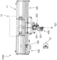
- the machines belonging to the production line of the insulating glass 1 are identified by four-digit numbers, in the order described above, reserving numeral 1000 for the automatic machine for forming the spacer frame obtained by the controlled and innovative extrusion of the spacer profile 7 (or by laying the spacer profile 5 made of elastic and flexible synthetic material).
- the other numerals used are: 2000 for the edge preparation machine, 3000 for the grinding machine, 4000 for the washing machine, 5000 for the coupling machine-press, 6000 for the gas loader, 7000 for the sealing machine.
- the dispensing assembly in one of the possible embodiments, comprises the following essential components: 401 plunger or syringe; 402 cylinder or chamber; 403 seal; 404 ball screw; 405 ball nut; 406 mechanical transmission, e.g. toothed wheel/chain type; 407 mechanical reducer; 408 synchronous electric motor.
- the dispenser further comprises the following accessory components, however indispensable: 409 three-way valve, which can be replaced by two two-way valves or by a two-way valve and a check valve; 410 pressure transducer; 411 pressure gage; 412 pressure relief valve or rupture disc; 413 manual valve for drawing or purging.
- 409 three-way valve which can be replaced by two two-way valves or by a two-way valve and a check valve
- 410 pressure transducer 411 pressure gage
- 412 pressure relief valve or rupture disc 413 manual valve for drawing or purging.
- the interrupted zone on the left is considered as known, in particular in part of figure 1 of US 2012/0180936 A1 , constituting the supply of the product to the dispensing assembly 400 as coming from the pump, typically of the double-acting type placed on the pressing plate of the product storage drum, for the feeding transfer to the dispensing assembly 400.
- first vertical side 1a second upper horizontal side 1b
- third vertical side 1c fourth lower horizontal side 1d.
- the unavoidable transients of the product flow at the corners in which the nozzle 301 must rotate by 90° are managed in the prior art by reducing the relative speed between nozzle 301 and the periphery of the glass pane and corresponding reduction of the product flow rate until the cancellation of such relative speed and the cancellation of the flow rate in the extrusion start and end position.
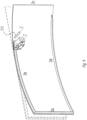
- the device claimed here by means of feelers 308, 308' or camera 309 located upstream of nozzle 301, controls the real position of said margin and, with feedback on the axis V if movement according to axis H is in progress or vice versa, adapts the position of the nozzle 301 as a function of the size to be controlled constituted by parameter p.
- the position of the real margin of the glass pane may be acquired in a station upstream of the spacer profile extrusion machine 7 provided with a scanner.
- the first advantage is that it is also possible to scan the glass pane on which the spacer profile 7 is not applied but which is intended to be coupled with the spacer frame 7 to constitute the insulating glass chamber 1, so that the axis H, V, ⁇ is not fully compensated, but to combine the signal of the sensor 308 or the sensors 308, 308' with the information acquired by the scanner to deposit the spacer profile in an interpolated position because the glass panes 2 which face the spacer frame 7 itself may not have the same shape errors but may be slightly different or worse the shape errors may be developed in the opposite direction.
- the second advantage concerns the elimination of the complicated mechanisms for the placement of the sensor 308 or the sensors 308, 308' and the management of the signals thereof.
- the disadvantage that is really negligible, consists in that the effect of the irregularities that the conveyors of the assemblies 100 and 100', actuating axis H, can induce on the positioning of the margins of the glass panes 2, which would instead actuate the feedback of sensor 308, is no longer filtered out.
- Such a disadvantage may be considered irrelevant because nowadays the conveyors are built with very reliable mechatronic components.
- the position at which the spacer profile is to be applied can be processed by the controller 306 from the signals or deriving from the sensors 308, 308', 309 or from the information deriving from the scanner according to algorithms which combine the needs of homogeneity of the parameter p with the aesthetic requirements of alignment of the spacer frame with the fixture or alignment between spacer frames belonging to the same multi-chamber insulating glass or in the case of excessively discordant geometries of the glass panes in the same insulating glass.
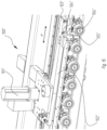
- one or more sensor(s)/feelers 308, 308' anticipate, in the direction of the relative movement (according to axes H, V, ⁇ ) the nozzle 301 to identify, by feeling, such position and transfer the information to the PLC 306 which processes the logic and power controls used for managing the axes H, V, ⁇ , so that such axes in single or interpolation respectively implement the correction for the positioning of the extrados of the spacer profile 7 at the distance p from the actual margin of the glass pane.
- the sensor/feeler function can alternatively be implemented by cameras or other electronic devices placed upstream of the nozzle 301.
- the function of the sensors/feelers 308, 308' (at least two to be able to detect with further advance also the position of the next side which has an angular offset with respect to the side concerned by the profile extrusion process) or of the camera 309 or another device, may be bypassed if, for the purposes of the final destination of the insulating glass 1, the exact geometry of the spacer profile takes precedence over the constancy of the parameter p relating to the distance from the margin of the glass pane.
- main INPUTS and OUTPUTS are the following:
- the operator interfaces from PLC 304 for parameters v, w, h, and from PLC 306 for parameter p are specified in sections 305 and 307 of the control console 12, respectively.
- the correct laying of the spacer profile according to the transverse direction Z is also very important because the geometry of its section and the initial bonding of the spacer profile - glass pane (before pressing) depend on the transverse positioning of the nozzle 301 and the thrust thereof, applied through the extruded material, towards the peripheral face of the glass pane.
- the present invention identifies the solution, original for this specific application, of controlling the approach of nozzle 301 towards the glass pane, irregular according to the transversal axis Z, both in position (first kind of mechanisms) and in force (second kind of mechanisms).
- This is achieved through an assembly of mechatronic components, those of the 500 series, partly dedicated to position control according to axis Z, partly dedicated to thrust control according to axis Z' coaxial with axis Z.
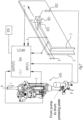
- a sensor 511 (shown in figure 9 in its scanning function of the face of the glass pane) communicates the real position of the face of the glass pane to PLC 310 and the synchronous motor 501 is activated in feedback through the mechanics 502, 503, 504, 507, 508a, 508b, 509a, 509b (shown in figure 10 ) moves the extrusion head 300 towards and from the face of the glass pane on the guides 509a, 509b belonging to the plate 201 of the vertical carriage 200.
- the slide 507 and blank 504 are not solid but instead are connected by means of the pneumatic cylinder 505 and the respective connecting rod 506.
- the operating principle consists in using the pneumatic pressure at the negative stroke chamber of the pneumatic cylinder to reduce the thrust of the extrusion nozzle 301 towards the face of the glass pane if such thrust is excessive, or in using the pneumatic pressure at the positive stroke chamber of the pneumatic cylinder to increase the thrust of the extrusion nozzle 301 towards the face of the glass pane if such thrust is insufficient.
- the linear transducer 510 has the function of preventing the piston of the pneumatic cylinder 505 from reaching the end of the stroke, by making the synchronous motor 501 trip for the new coarse but centered positioning according to axis Z.
- the positioning of the extrusion head 300 according to the axis Z as a function of the sensor signal 511 does not have sufficient reliability, the accuracy deriving from the resolution of the sensor signal 511, the control of the drives, the accuracy of the mechanical processes, the clearances, the temperature, etc., a resolution not better than ⁇ 0.5 mm is achieved, which implies that, in case of detachment of the nozzle 301 from the face of the glass pane, a non-definition of the section of the spacer profile in extrusion, a non-contact of the product with the face of the glass pane and a leakage of the product towards the face itself with respective fouling, in case of interference between the nozzle 301 and the face of the glass pane, damage to the latter.
- the pneumatic cylinder 505 may be replaced by an equivalent or alternative actuator.
- the body 504, to which the ball nut 503 is constrained, is not rigidly attached to the slide 507 but interfaced with it through an elastic connection consisting of the pneumatic "compensating" cylinder 505 the stem 506 of which is screwed and locked onto a part of the slide 507. It is needless to say, therefore, that as a function of the pressures which can be established in the pneumatic cylinder 505, both in the negative stroke chamber and in the positive stroke chamber, the sealing head 300 and with it the portion of the extrusion nozzle 301 approaching against the face of the glass pane can apply a "soft" or adequate thrust against the face of the glass pane.
- the component 510 shown in figure 10 consists of a potentiometer which detects the position of the piston inside the pneumatic cylinder 505 and provides feedback to the controller (PLC) 310 so that, by driving the actuator 501, a position of the pneumatic cylinder 505 with respect to the piston contained inside it is restored rather centered, so that there is a working range for the "soft damping" of the nozzle 301 towards the face of the glass pane. Otherwise, there is a risk that the piston reaching the limit stop the nozzle 301 presses excessively against the face of the glass pane, and reaching the positive limit stop the nozzle 301 detaches from the face of the glass pane.
- PLC controller
- the main INPUTS and OUTPUTS for managing such double feedback mechanisms are: [00113]
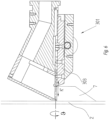
- Such control of the force F is important because the extrusion behavior of the product also depends on the viscosity of the product and the viscosity also depends on the temperature, and the product flow from the nozzle 301 is a fluid-dynamic regime which moves the mouth of the nozzle 301 away ( figure 6 shows this situation at the contour).
- the possibility of selecting the value F from the operator interface 311 and its effective control operated by the PLC 310 are, therefore, functional to achieving a profile having a homogeneous section and thrust suited for the first constraint towards the glass pane, i.e. the constraint which must start the reaction with the micro-roughness of the glass and effectively support the formed frame until the coupling and pressing phase described above in the production cycle of insulating glass 1.
- a further expedient is to install the dispensing assembly on the carriage 200, to work with lower product pressures in the circuits, the solution shown in figures 2 and 4 , so that the path of the product to be fed to the nozzle 301 is as short as possible, moreover the same path including, in the case of possible future two-component product, a static mixer which implies a pressure drop caused by the energy required for mixing.
- controllers such as the section S of the syringe or the transmission ratios of the various kinematic mechanisms, because they are fixed data.
- the product used to manufacture such spacer frame is generally a single-component product and is hot extruded, being a thermoplastic product, so that the dispenser 400 shown in figures 5A, 5B and conduction circuits to the extrusion nozzle 301 and the extrusion nozzle 301 shown in figures 6 to 11 are heat-controlled, as are the storage drums of the product with respective pressure plates, pumps and transfer circuits (typically there are two drums because when one finishes the other is already preheated and ready to switch to the dispensing assembly 400).
- h is kept constant (or changes discontinuously by replacing the extrusion nozzle assembly 301 and w is varied as a function of the composition of the insulating glass 1, with the possibility of continuous selection by means of the adjustment of the shutter 303 of the nozzle 301, normally obtained by means of an actuator the position of which is feedback-controlled (axis K').
- a variant of the known part of the invention and, in turn, not inventive, however residing practically in the software alone and therefore using the same devices described above for the rectangular glass panes 2 exposed hereto is the logical combination of synchronous drives, respectively: of horizontal translation according to the axes H, H' of the glass pane 2 by means of synchronous motors; of vertical translation according to the axis V of the head 200 by means of synchronous motor; of rotation according to the axis ⁇ of the head 300 by means of synchronous motor; of control, in adjustment or control, of the shutter 303 of the nozzle 301 to allow the extrusion process of the spacer profile 7 and the forming of the spacer frame on a glass pane 2l having a shape different from rectangular because it is regular or irregular polygonal or on a glass pane 2r having a different shape from rectangular because it is curvilinear or on a glass pane 2lr having a different shape from rectangular because it contains both straight and curvilinear parts.
- the carriage 100'' moves according to the axis H'', parallel to the axes H and H', actuated by a synchronous motor 101'', and is positioned in a field in which it is desired to stop a reference of the glass pane 2, 2', 2", 2′′′, etc., 2l, 2r, 2lr, e.g. the tail 2c, to achieve a precise start of the formation of the spacer frame 7, 7', 7", etc., 5, 5', 5'', etc. at the position p relative to the margin of the glass pane.
- Such carriage carries an arm 102", with movement for protruding or retracting relative to the sliding plane 900 in the direction, and such arm bears: sensors 103", 104'' for actuating the decelerations of the axes H and H' and plate 105'' equipped with a microswitch 106'' to actuate the precise stopping of the glass pane.
- the materials and dimensions can be any depending on the requirements, in particular, deriving from the dimensions (base and height) and/or the shape of the glass panes 2, 2', 2", 2′′′, 2M, 2'm, 2''m that will form insulating glass 1 once the spacer profile 7 has been extruded to form the spacer frame and a second pane has been coupled and possibly further spacer frames and glass panes have been coupled.
Landscapes
- Engineering & Computer Science (AREA)
- Mechanical Engineering (AREA)
- Civil Engineering (AREA)
- Structural Engineering (AREA)
- Securing Of Glass Panes Or The Like (AREA)
- Joining Of Glass To Other Materials (AREA)
- Seal Device For Vehicle (AREA)
Claims (12)
- Vorrichtung für die Extrusion und das Anbringen bzw. Aufbringen eines Abstandhalterprofils von bzw. für Isolierglas (1), insbesondere für eine Maschine, die angepasst ist, den Abstandhalterrahmen (7) direkt gegen eine oder mehrere der Glasscheiben zusammenzusetzen, die das Isolierglas (1) bilden, und zwar ausgehend von einem thermoplastischen Produkt,
dadurch gekennzeichnet, dass zumindest ein Fühler (308) der Vorrichtung, der sich stromaufwärts der Extrusionsdüse (301) der Vorrichtung befindet, die Position des Rands (2a, 2b, 2c, 2d) der Glasscheibe (2, 2', 2", 2‴ etc.) identifiziert und das Positionssignal an eine Steuerung bzw. Regelung (306) der Vorrichtung überträgt, die über die Achsen H, V, ϑ, die von Synchronmotoren (101, 101', 201, 301) der Vorrichtung angetrieben werden, eine Beibehaltung einer gegenseitigen Position von Düse (301) - Rand der Glasscheibe (2, 2', 2", 2‴ etc.) in einem Abstand p, der über die Bedienerschnittstelle (307) der Vorrichtung festgelegt werden kann, betätigt bzw. bewirkt. - Vorrichtung nach Anspruch 1, wobei zumindest für die vollständig kurvenförmige Form 2r und die polygonale Form mit einer oder mehreren kurvenförmigen Seiten 21r der Glasscheibe die Position des Rands der Glasscheibe durch eine Kamera oder eine andere optische Vorrichtung (309) identifiziert wird, die sich stromaufwärts der Extrusionsdüse (301) befindet.
- Vorrichtung nach einem der Ansprüche 1 bis 2, wobei die Position des Rands der Glasscheibe (2, 2', 2", 2‴ etc.) stromaufwärts durch einen Scanner identifiziert und an die Steuerung bzw. Regelung (306) übertragen wird.
- Vorrichtung nach einem der Ansprüche 1 bis 3, wobei die Position des Rands der Glasscheibe (2, 2', 2", 2‴ etc.), die entweder aus den von den Sensoren (308, 308', 309) stammenden Typsignalen oder aus den von dem Scanner stammenden Informationen gewonnen wird, von der Steuerung bzw. Regelung (306) gemäß Algorithmen verarbeitet wird, welche die Anforderungen an Homogenität des Parameters p mit den ästhetischen Anforderungen einer Ausrichtung des Abstandhalterrahmens mit der Halterung bzw. Vorrichtung oder einer Ausrichtung zwischen Abstandhalterrahmen kombinieren, die zu demselben Mehrkammer-Isolierglas gehören, oder in dem Fall von übermäßig unterschiedlichen Geometrien der Glasscheiben desselben Isolierglases.
- Vorrichtung nach einem der Ansprüche 1 bis 4, wobei das Abstandhalterprofil vom flexiblen, geschäumten Synthetikmaterialtyp ist, um den Abstandhalterrahmen (5, 5', 5", etc.) herzustellen.
- Vorrichtung nach einem der vorhergehenden Ansprüche, wobei die Nullposition der Glasscheibe (2, 2', 2", 2"', etc.), gegen die entweder die Extrusion des Abstandhalterprofils (7, 7', 7", etc.) oder die Anbringung bzw. Aufbringung des Abstandhalterprofils (5, 5', 5", etc.) beginnt, durch Verwendung eines Schlittens 100" erreicht wird, der sich entlang der Achse H" parallel zu den Achsen H und H' bewegt und von einem Synchronmotor (101") betätigt bzw. angetrieben wird, der in einem Feld bzw. Bereich positioniert ist, in dem es gewünscht ist, eine Referenz der Glasscheibe (2, 2', 2", 2‴, etc., 21, 2r, 21r), z. B. das Ende 2c, zu stoppen, um einen präzisen Start der Bildung des Abstandhalterrahmens (7, 7', 7", etc., 5, 5', 5", etc.) an Position p relativ zu dem Rand der Glasscheibe zu erreichen, wobei dieser Schlitten einen Arm (102") trägt, mit Bewegung entweder zum Vorschieben oder Zurückziehen in Bezug auf die Gleitebene (900) entlang einer Richtung Z, wobei dieser Arm trägt: Sensoren (103", 104") zum Betätigen bzw. Bewirken der Verlangsamungen der Achsen H und H' und eine Platte (105"), die mit einem Mikroschalter (106") zum Betätigen bzw. Bewirken des präzisen Stopps der Glasscheibe versehen ist.
- Vorrichtung nach Anspruch 6, wobei die Nullposition der Glasscheibe (2, 2', 2", 2‴, etc.), gegen die entweder die Extrusion des Abstandhalterprofils (7, 7', 7", etc.) oder die Anbringung bzw. Aufbringung des Abstandhalterprofils (5, 5', 5", etc.) beginnt, durch einen Schlitten (100") erreicht wird, der sich entlang der Achse H" parallel zu den Achsen H und H' bewegt und von einem Synchronmotor (101") betätigt bzw. angetrieben wird und ein mechanisches System trägt, das aus einer Leerlaufrolle besteht, die von einer Feder angetrieben wird und verschiebbar an bzw. auf der Führung eines Stütz- bzw. Trägerarms (102") montiert ist, mit Bewegung entweder zum Vorschieben oder Zurückziehen relativ zu der Gleitebene (900) entlang der Richtung Z, wobei die relative Position des Radarms von einem Potentiometer gemessen wird, dessen Signal den Stopp der Achsen H und H' aktiviert, wobei sich der Schlitten selber so positioniert, dass das Wirkungsfeld bzw. der Wirkungsbereich des Potentiometers in die Position fällt, in der es gewünscht ist, eine Referenz der Glasscheibe (2, 2', 2", 2‴ etc., 21, 2r, 21r) mit Genauigkeit zu stoppen.
- Vorrichtung für die Extrusion und das Anbringen bzw. Aufbringen eines Abstandhalterprofils aus Isolierglas (1), insbesondere für eine Maschine, die angepasst ist, den Abstandhalterrahmen (7) direkt gegen eine oder mehrere der Glasscheiben zusammenzusetzen, die das Isolierglas (1) bilden, und zwar ausgehend von einem thermoplastischen Produkt,
dadurch gekennzeichnet, dass die Extrusionsdüse (301) der Vorrichtung durch die Mechanismen der Vorrichtung, die umfasst: Aktor (501); mechanische Übertragung bzw. Transmission (502, 503); Stütze bzw. Träger (504); Aktor/Kompensator (505); Verbindung (506) zum Schieber (507); Wandler (510), die sich alle in dem Synchronschlitten (200) befinden; Sensor (511), der sich in dem Extrusionskopf (300) befindet, die miteinander verbunden sind und in Verbindung mit der Lage der Umfangsfläche der Glasscheibe (2, 2', 2", 2‴, etc.) arbeiten, während der relativen Bewegung der Düse (301) - Glasscheibe (2, 2', 2", 2‴, etc.) die Extrusionsdüse (301) nahtlos der tatsächlichen Position, nicht der theoretischen Position, dieser Fläche entlang der Querachse Z folgen lässt, die sich aufgrund der Nichtplanarität der Glasscheibe (2, 2', 2", 2"', etc.) von der theoretischen unterscheidet, mit Mitteln der Vorrichtung zum Steuern bzw. Regeln der von der Düse (301) gegen die Fläche der Glasscheibe ausgeübten Kraft, neben Positionssteuerungs- bzw. -regelungsmitteln in den Umfangsabschnitten, in denen die Scheibe selbst die Extrusion des Abstandhalterprofils (7, 7', 7", etc.) empfängt bzw. erhält. - Verfahren für die Extrusion und das Anbringen bzw. Aufbringen eines Abstandhalterprofils aus Isolierglas (1) unter Verwendung der Vorrichtung der Ansprüche 1 bis 7, insbesondere für eine Maschine, die angepasst ist, den Abstandhalterrahmen (7) direkt gegen eine oder mehrere der Glasscheiben zusammenzusetzen, die das Isolierglas (1) bilden, und zwar ausgehend von einem thermoplastischen Produkt,
dadurch gekennzeichnet, dass die gegenseitige Position von Düse (301) - Rand der Glasplatte (2, 2', 2", 2‴, etc.) auf einem konstanten Abstand p gehalten wird, der über die Bedienerschnittstelle (307) festgelegt werden kann, wobei die tatsächliche Position des Rands der Glasscheibe verfolgt wird, die sich von der theoretischen geometrischen Position unterscheiden kann, so dass der Umfangshohlraum, der durch die Innenflächen der Glasscheibe und die Außenfläche des Abstandhalterprofils (7, 7', 7", etc.) identifiziert ist, entlang des gesamten Umfangs des Isolierglases (1) homogen ist, da er zum Befüllen mit dem sekundären Dichtungsmittel bestimmt ist, das strukturelle Bindungs- und Gas- und Wasserdampfdichtfunktionen erfüllt. - Verfahren für die Extrusion und das Anbringen bzw. Aufbringen eines Abstandhalterprofils für Isolierglas (1) unter Verwendung der Vorrichtung nach Anspruch 8, insbesondere für eine Maschine, die angepasst ist, den Abstandhalterrahmen (7) direkt gegen eine oder mehrere der Glasscheiben zusammenzusetzen, die das Isolierglas (1) bilden, und zwar ausgehend von einem thermoplastischen Produkt,
dadurch gekennzeichnet, dass die Position und Schubkraft der Düse (301) in Richtung der Fläche der Glasscheibe (2, 2', 2", 2‴, etc.) entlang der Querachse Z über den gesamten Extrusionsweg des Abstandhalterprofils (7, 7', 7", etc.) gesteuert bzw. geregelt wird. - Verfahren nach Anspruch 9 oder 10, wobei das Abstandhalterprofil vom flexiblen, geschäumten Synthetikmaterialtyp (5, 5', 5", etc.) ist.
- Verfahren nach Anspruch 11, wobei die Position und Schubkraft des Führungs- und Verlegewerkzeugs des Abstandhalterprofils in Richtung der Fläche der Glasscheibe (2, 2', 2", 2‴, etc.) gemäß der Querachse Z über den gesamten Anbringungs- bzw. Aufbringungsweg des Abstandhalterprofils (5, 5', 5", etc.) gesteuert bzw. geregelt wird.
Applications Claiming Priority (2)
| Application Number | Priority Date | Filing Date | Title |
|---|---|---|---|
| IT102019000016250A IT201900016250A1 (it) | 2019-09-13 | 2019-09-13 | Dispositivo e procedimento per l'estrusione e l'applicazione di profilo distanziatore del vetro isolante |
| PCT/IB2020/058467 WO2021048811A1 (en) | 2019-09-13 | 2020-09-11 | Device and procedure for extrusion and application of spacer profile of an insulating glass |
Publications (2)
| Publication Number | Publication Date |
|---|---|
| EP4028623A1 EP4028623A1 (de) | 2022-07-20 |
| EP4028623B1 true EP4028623B1 (de) | 2025-03-12 |
Family
ID=69375724
Family Applications (1)
| Application Number | Title | Priority Date | Filing Date |
|---|---|---|---|
| EP20786596.5A Active EP4028623B1 (de) | 2019-09-13 | 2020-09-11 | Vorrichtung und verfahren zum extrudieren und anwenden von abstandhalterprofilen aus einem isolierglas |
Country Status (6)
| Country | Link |
|---|---|
| US (1) | US12180782B2 (de) |
| EP (1) | EP4028623B1 (de) |
| CA (1) | CA3148941A1 (de) |
| FI (1) | FI4028623T3 (de) |
| IT (1) | IT201900016250A1 (de) |
| WO (1) | WO2021048811A1 (de) |
Families Citing this family (1)
| Publication number | Priority date | Publication date | Assignee | Title |
|---|---|---|---|---|
| IT202300018225A1 (it) * | 2023-09-05 | 2025-03-05 | Forel S P A Unipersonale | Apparato e procedimento per la calibrazione di un distanziatore termoplastico |
Family Cites Families (22)
| Publication number | Priority date | Publication date | Assignee | Title |
|---|---|---|---|---|
| DE8600068U1 (de) * | 1986-01-03 | 1986-02-13 | Ratiotechnik Rationalisierungstechnik und Automation GmbH u. Co KG, 3300 Braunschweig | Gerät zur Montage eines flexiblen Abstandhalters auf einer Glasscheibe |
| US5045146A (en) * | 1989-06-08 | 1991-09-03 | Tremco, Inc. | Tape applicator with corner forming device |
| AT399497B (de) * | 1990-01-11 | 1995-05-26 | Lisec Peter | Vorrichtung zum auftragen von plastischen massen |
| AT399867B (de) * | 1990-01-11 | 1995-08-25 | Lisec Peter | Anlage zur herstellung von isolierglasscheiben |
| DE4433749C2 (de) | 1994-09-22 | 2002-11-21 | Lenhardt Maschinenbau | Verfahren und Vorrichtung zum Auftragen eines plastischen Abstandhalters auf eine Glastafel |
| DE19632063C1 (de) | 1996-08-09 | 1998-03-12 | Lenhardt Maschinenbau | Verfahren und Vorrichtung zum Auftragen eines plastischen Abstandhalters auf eine Glastafel |
| DE19632062C1 (de) | 1996-08-09 | 1998-03-05 | Lenhardt Maschinenbau | Verfahren und Vorrichtung zum Auftragen eines plastischen Abstandhalters auf eine Glastafel |
| JP3237544B2 (ja) * | 1996-10-11 | 2001-12-10 | 富士通株式会社 | 平面表示パネルの製造方法及び平面表示パネル |
| US6231917B1 (en) * | 1998-06-19 | 2001-05-15 | Kabushiki Kaisha Toshiba | Method of forming liquid film |
| DE10027043B4 (de) * | 2000-06-02 | 2004-08-19 | Webasto Vehicle Systems International Gmbh | Verfahren und Vorrichtung zum Auftragen von Haftvermittler auf einen Glasscheibenrand |
| US20040118001A1 (en) * | 2002-12-20 | 2004-06-24 | Turpin Larry Wayne | Combined laser level tape for fence construction |
| JP4539560B2 (ja) * | 2003-06-26 | 2010-09-08 | 横浜ゴム株式会社 | 複層ガラスの製造に使用するスペーサ形成装置 |
| ITTV20080032A1 (it) * | 2008-02-20 | 2009-08-21 | For El Base Di Vianello Fortunato & C Snc | Dispositivo automatico e procedimento automatico per la sigillatura perimetrale del vetro isolante composto da almeno due lastre di vetro ed almeno un telaio distanziatore avente profilo complesso differente dal tradizionale. |
| DE112009004884B4 (de) * | 2009-06-09 | 2019-03-14 | The Yokohama Rubber Co., Ltd. | Verfahren und Vorrichtung für das Formen einer Verglasungsdichtung auf eine mehrschichtige Glasplatte |
| DE102009035002A1 (de) | 2009-07-24 | 2011-01-27 | Bystronic Lenhardt Gmbh | Verfahren zum Herstellen einer Isolierglasscheibe |
| DE102011011549A1 (de) * | 2011-02-17 | 2012-08-23 | Sollingglas Bau U. Veredelungs Gmbh & Co Kg | Randverbund einer Isolierverglasung |
| DE112012002462B4 (de) * | 2011-06-14 | 2016-01-07 | The Yokohama Rubber Co., Ltd. | Verfahren und Vorrichtung zum Herstellen einer Glasplatte mit einer Verglasungsdichtung |
| US8997685B2 (en) * | 2012-08-07 | 2015-04-07 | Erdman Automation Corporation | Single axis applicator |
| UA115001C2 (uk) | 2014-01-28 | 2017-08-28 | Лісец Аустріа Гмбх | Спосіб і пристрій для виготовлення термопластичних дистанційних прокладок |
| IT201600082108A1 (it) | 2016-08-04 | 2018-02-04 | Forel Spa | Dispositivo dosatore per la estrusione di un sigillante bicomponente o monocomponente. |
| IT201800009336A1 (it) * | 2018-10-12 | 2020-04-12 | Forel Spa | Macchina automatica e procedimento automatico per la sigillatura del bordo perimetrale del vetro isolante costituito da lastre di vetro di dimensioni differenti |
| EP3877622B1 (de) * | 2018-11-07 | 2024-12-11 | VKR Holding A/S | Verfahren zum aufbringen eines dichtungsmaterials bei der herstellung einer vig-einheit |
-
2019
- 2019-09-13 IT IT102019000016250A patent/IT201900016250A1/it unknown
-
2020
- 2020-09-11 EP EP20786596.5A patent/EP4028623B1/de active Active
- 2020-09-11 FI FIEP20786596.5T patent/FI4028623T3/fi active
- 2020-09-11 WO PCT/IB2020/058467 patent/WO2021048811A1/en not_active Ceased
- 2020-09-11 CA CA3148941A patent/CA3148941A1/en active Pending
- 2020-09-11 US US17/639,656 patent/US12180782B2/en active Active
Also Published As
| Publication number | Publication date |
|---|---|
| FI4028623T3 (fi) | 2025-04-24 |
| EP4028623A1 (de) | 2022-07-20 |
| CA3148941A1 (en) | 2021-03-18 |
| WO2021048811A1 (en) | 2021-03-18 |
| US20220290491A1 (en) | 2022-09-15 |
| US12180782B2 (en) | 2024-12-31 |
| IT201900016250A1 (it) | 2021-03-13 |
Similar Documents
| Publication | Publication Date | Title |
|---|---|---|
| EP2177703B1 (de) | Automatische Maschine zum Auftragen eines Abstandhalterprofils auf eine Glasscheibe sowie Verfahren dafür | |
| US7922842B2 (en) | Automatic device and method for perimetric sealing of insulating glazing units | |
| US20080092594A1 (en) | Automatic machine and automatic method for grinding the edges of glass panes | |
| EP1769885B1 (de) | Automatische Machine zum Schleifen und Besäumen von Glasplattenkanten | |
| US12180782B2 (en) | Device and procedure for extrusion and application of spacer profile of an insulating glass | |
| US7357169B2 (en) | Automatic machine for applying a spacer tape made of flexible material to flat glass panes, particularly glass panes for manufacturing double-glazing units | |
| US20040259475A1 (en) | Automatic machine for grinding the borders of glass panes | |
| US20240286853A1 (en) | Device and method for unloading insulating glass from an insulating glass production line and the subsequent conditioning | |
| EP2460971B1 (de) | Verfahren zum Versiegeln einer Umfangsnut einer Isolierverglasung | |
| EP3864247B1 (de) | Automatische abdichtungsmaschine und verfahren zum automatischen abdichten der umfangskante von isolierglas aus glasscheiben mit unterschiedlichen abmessungen | |
| US11248414B2 (en) | Dosage device for continuously extruding and applying a spacer profile of an insulating glazing unit | |
| US10890026B2 (en) | Automatic machine for alternable application of a plurality of flexible spacer profiles on a glass sheet | |
| US11639628B2 (en) | Automatic machine and automatic method for sealing the perimetric edge of the insulating glazing unit having irregular geometry |
Legal Events
| Date | Code | Title | Description |
|---|---|---|---|
| STAA | Information on the status of an ep patent application or granted ep patent |
Free format text: STATUS: UNKNOWN |
|
| STAA | Information on the status of an ep patent application or granted ep patent |
Free format text: STATUS: THE INTERNATIONAL PUBLICATION HAS BEEN MADE |
|
| PUAI | Public reference made under article 153(3) epc to a published international application that has entered the european phase |
Free format text: ORIGINAL CODE: 0009012 |
|
| STAA | Information on the status of an ep patent application or granted ep patent |
Free format text: STATUS: REQUEST FOR EXAMINATION WAS MADE |
|
| 17P | Request for examination filed |
Effective date: 20220217 |
|
| AK | Designated contracting states |
Kind code of ref document: A1 Designated state(s): AL AT BE BG CH CY CZ DE DK EE ES FI FR GB GR HR HU IE IS IT LI LT LU LV MC MK MT NL NO PL PT RO RS SE SI SK SM TR |
|
| DAV | Request for validation of the european patent (deleted) | ||
| DAX | Request for extension of the european patent (deleted) | ||
| P01 | Opt-out of the competence of the unified patent court (upc) registered |
Effective date: 20230525 |
|
| GRAP | Despatch of communication of intention to grant a patent |
Free format text: ORIGINAL CODE: EPIDOSNIGR1 |
|
| STAA | Information on the status of an ep patent application or granted ep patent |
Free format text: STATUS: GRANT OF PATENT IS INTENDED |
|
| INTG | Intention to grant announced |
Effective date: 20241008 |
|
| GRAS | Grant fee paid |
Free format text: ORIGINAL CODE: EPIDOSNIGR3 |
|
| GRAA | (expected) grant |
Free format text: ORIGINAL CODE: 0009210 |
|
| STAA | Information on the status of an ep patent application or granted ep patent |
Free format text: STATUS: THE PATENT HAS BEEN GRANTED |
|
| AK | Designated contracting states |
Kind code of ref document: B1 Designated state(s): AL AT BE BG CH CY CZ DE DK EE ES FI FR GB GR HR HU IE IS IT LI LT LU LV MC MK MT NL NO PL PT RO RS SE SI SK SM TR |
|
| REG | Reference to a national code |
Ref country code: GB Ref legal event code: FG4D |
|
| REG | Reference to a national code |
Ref country code: CH Ref legal event code: EP |
|
| REG | Reference to a national code |
Ref country code: DE Ref legal event code: R096 Ref document number: 602020047635 Country of ref document: DE |
|
| REG | Reference to a national code |
Ref country code: IE Ref legal event code: FG4D |
|
| REG | Reference to a national code |
Ref country code: FI Ref legal event code: FGE |
|
| PG25 | Lapsed in a contracting state [announced via postgrant information from national office to epo] |
Ref country code: RS Free format text: LAPSE BECAUSE OF FAILURE TO SUBMIT A TRANSLATION OF THE DESCRIPTION OR TO PAY THE FEE WITHIN THE PRESCRIBED TIME-LIMIT Effective date: 20250612 |
|
| PG25 | Lapsed in a contracting state [announced via postgrant information from national office to epo] |
Ref country code: ES Free format text: LAPSE BECAUSE OF FAILURE TO SUBMIT A TRANSLATION OF THE DESCRIPTION OR TO PAY THE FEE WITHIN THE PRESCRIBED TIME-LIMIT Effective date: 20250312 |
|
| REG | Reference to a national code |
Ref country code: LT Ref legal event code: MG9D |
|
| PG25 | Lapsed in a contracting state [announced via postgrant information from national office to epo] |
Ref country code: NO Free format text: LAPSE BECAUSE OF FAILURE TO SUBMIT A TRANSLATION OF THE DESCRIPTION OR TO PAY THE FEE WITHIN THE PRESCRIBED TIME-LIMIT Effective date: 20250612 |
|
| PG25 | Lapsed in a contracting state [announced via postgrant information from national office to epo] |
Ref country code: HR Free format text: LAPSE BECAUSE OF FAILURE TO SUBMIT A TRANSLATION OF THE DESCRIPTION OR TO PAY THE FEE WITHIN THE PRESCRIBED TIME-LIMIT Effective date: 20250312 |
|
| REG | Reference to a national code |
Ref country code: NL Ref legal event code: MP Effective date: 20250312 |
|
| PG25 | Lapsed in a contracting state [announced via postgrant information from national office to epo] |
Ref country code: LV Free format text: LAPSE BECAUSE OF FAILURE TO SUBMIT A TRANSLATION OF THE DESCRIPTION OR TO PAY THE FEE WITHIN THE PRESCRIBED TIME-LIMIT Effective date: 20250312 |
|
| PG25 | Lapsed in a contracting state [announced via postgrant information from national office to epo] |
Ref country code: GR Free format text: LAPSE BECAUSE OF FAILURE TO SUBMIT A TRANSLATION OF THE DESCRIPTION OR TO PAY THE FEE WITHIN THE PRESCRIBED TIME-LIMIT Effective date: 20250613 Ref country code: BG Free format text: LAPSE BECAUSE OF FAILURE TO SUBMIT A TRANSLATION OF THE DESCRIPTION OR TO PAY THE FEE WITHIN THE PRESCRIBED TIME-LIMIT Effective date: 20250312 |
|
| PG25 | Lapsed in a contracting state [announced via postgrant information from national office to epo] |
Ref country code: NL Free format text: LAPSE BECAUSE OF FAILURE TO SUBMIT A TRANSLATION OF THE DESCRIPTION OR TO PAY THE FEE WITHIN THE PRESCRIBED TIME-LIMIT Effective date: 20250312 |
|
| PG25 | Lapsed in a contracting state [announced via postgrant information from national office to epo] |
Ref country code: SE Free format text: LAPSE BECAUSE OF FAILURE TO SUBMIT A TRANSLATION OF THE DESCRIPTION OR TO PAY THE FEE WITHIN THE PRESCRIBED TIME-LIMIT Effective date: 20250312 |
|
| REG | Reference to a national code |
Ref country code: CH Ref legal event code: U11 Free format text: ST27 STATUS EVENT CODE: U-0-0-U10-U11 (AS PROVIDED BY THE NATIONAL OFFICE) Effective date: 20251001 |
|
| PG25 | Lapsed in a contracting state [announced via postgrant information from national office to epo] |
Ref country code: SM Free format text: LAPSE BECAUSE OF FAILURE TO SUBMIT A TRANSLATION OF THE DESCRIPTION OR TO PAY THE FEE WITHIN THE PRESCRIBED TIME-LIMIT Effective date: 20250312 |
|
| PG25 | Lapsed in a contracting state [announced via postgrant information from national office to epo] |
Ref country code: PT Free format text: LAPSE BECAUSE OF FAILURE TO SUBMIT A TRANSLATION OF THE DESCRIPTION OR TO PAY THE FEE WITHIN THE PRESCRIBED TIME-LIMIT Effective date: 20250714 |
|
| PGFP | Annual fee paid to national office [announced via postgrant information from national office to epo] |
Ref country code: FI Payment date: 20250917 Year of fee payment: 6 |
|
| PGFP | Annual fee paid to national office [announced via postgrant information from national office to epo] |
Ref country code: DE Payment date: 20250923 Year of fee payment: 6 |
|
| PG25 | Lapsed in a contracting state [announced via postgrant information from national office to epo] |
Ref country code: PL Free format text: LAPSE BECAUSE OF FAILURE TO SUBMIT A TRANSLATION OF THE DESCRIPTION OR TO PAY THE FEE WITHIN THE PRESCRIBED TIME-LIMIT Effective date: 20250312 |
|
| PGFP | Annual fee paid to national office [announced via postgrant information from national office to epo] |
Ref country code: TR Payment date: 20250910 Year of fee payment: 6 Ref country code: IT Payment date: 20250704 Year of fee payment: 6 |
|
| PGFP | Annual fee paid to national office [announced via postgrant information from national office to epo] |
Ref country code: AT Payment date: 20250917 Year of fee payment: 6 |
|
| PG25 | Lapsed in a contracting state [announced via postgrant information from national office to epo] |
Ref country code: EE Free format text: LAPSE BECAUSE OF FAILURE TO SUBMIT A TRANSLATION OF THE DESCRIPTION OR TO PAY THE FEE WITHIN THE PRESCRIBED TIME-LIMIT Effective date: 20250312 Ref country code: CZ Free format text: LAPSE BECAUSE OF FAILURE TO SUBMIT A TRANSLATION OF THE DESCRIPTION OR TO PAY THE FEE WITHIN THE PRESCRIBED TIME-LIMIT Effective date: 20250312 |
|
| PG25 | Lapsed in a contracting state [announced via postgrant information from national office to epo] |
Ref country code: RO Free format text: LAPSE BECAUSE OF FAILURE TO SUBMIT A TRANSLATION OF THE DESCRIPTION OR TO PAY THE FEE WITHIN THE PRESCRIBED TIME-LIMIT Effective date: 20250312 |
|
| PG25 | Lapsed in a contracting state [announced via postgrant information from national office to epo] |
Ref country code: SK Free format text: LAPSE BECAUSE OF FAILURE TO SUBMIT A TRANSLATION OF THE DESCRIPTION OR TO PAY THE FEE WITHIN THE PRESCRIBED TIME-LIMIT Effective date: 20250312 |
|
| PG25 | Lapsed in a contracting state [announced via postgrant information from national office to epo] |
Ref country code: IS Free format text: LAPSE BECAUSE OF FAILURE TO SUBMIT A TRANSLATION OF THE DESCRIPTION OR TO PAY THE FEE WITHIN THE PRESCRIBED TIME-LIMIT Effective date: 20250712 |
|
| REG | Reference to a national code |
Ref country code: DE Ref legal event code: R097 Ref document number: 602020047635 Country of ref document: DE |
|
| PG25 | Lapsed in a contracting state [announced via postgrant information from national office to epo] |
Ref country code: DK Free format text: LAPSE BECAUSE OF FAILURE TO SUBMIT A TRANSLATION OF THE DESCRIPTION OR TO PAY THE FEE WITHIN THE PRESCRIBED TIME-LIMIT Effective date: 20250312 |
|
| PLBE | No opposition filed within time limit |
Free format text: ORIGINAL CODE: 0009261 |
|
| STAA | Information on the status of an ep patent application or granted ep patent |
Free format text: STATUS: NO OPPOSITION FILED WITHIN TIME LIMIT |
|
| PGFP | Annual fee paid to national office [announced via postgrant information from national office to epo] |
Ref country code: CH Payment date: 20251001 Year of fee payment: 6 |
|
| REG | Reference to a national code |
Ref country code: CH Ref legal event code: L10 Free format text: ST27 STATUS EVENT CODE: U-0-0-L10-L00 (AS PROVIDED BY THE NATIONAL OFFICE) Effective date: 20260121 |
|
| 26N | No opposition filed |
Effective date: 20251215 |