EP4028280B1 - Dispositif de recharge de batteries de véhicules électriques par induction - Google Patents
Dispositif de recharge de batteries de véhicules électriques par induction Download PDFInfo
- Publication number
- EP4028280B1 EP4028280B1 EP20788847.0A EP20788847A EP4028280B1 EP 4028280 B1 EP4028280 B1 EP 4028280B1 EP 20788847 A EP20788847 A EP 20788847A EP 4028280 B1 EP4028280 B1 EP 4028280B1
- Authority
- EP
- European Patent Office
- Prior art keywords
- vehicle
- retractable post
- application
- allowing
- integrated
- Prior art date
- Legal status (The legal status is an assumption and is not a legal conclusion. Google has not performed a legal analysis and makes no representation as to the accuracy of the status listed.)
- Active
Links
Images

Classifications
-
- B—PERFORMING OPERATIONS; TRANSPORTING
- B60—VEHICLES IN GENERAL
- B60L—PROPULSION OF ELECTRICALLY-PROPELLED VEHICLES; SUPPLYING ELECTRIC POWER FOR AUXILIARY EQUIPMENT OF ELECTRICALLY-PROPELLED VEHICLES; ELECTRODYNAMIC BRAKE SYSTEMS FOR VEHICLES IN GENERAL; MAGNETIC SUSPENSION OR LEVITATION FOR VEHICLES; MONITORING OPERATING VARIABLES OF ELECTRICALLY-PROPELLED VEHICLES; ELECTRIC SAFETY DEVICES FOR ELECTRICALLY-PROPELLED VEHICLES
- B60L53/00—Methods of charging batteries, specially adapted for electric vehicles; Charging stations or on-board charging equipment therefor; Exchange of energy storage elements in electric vehicles
- B60L53/10—Methods of charging batteries, specially adapted for electric vehicles; Charging stations or on-board charging equipment therefor; Exchange of energy storage elements in electric vehicles characterised by the energy transfer between the charging station and the vehicle
- B60L53/12—Inductive energy transfer
-
- B—PERFORMING OPERATIONS; TRANSPORTING
- B60—VEHICLES IN GENERAL
- B60L—PROPULSION OF ELECTRICALLY-PROPELLED VEHICLES; SUPPLYING ELECTRIC POWER FOR AUXILIARY EQUIPMENT OF ELECTRICALLY-PROPELLED VEHICLES; ELECTRODYNAMIC BRAKE SYSTEMS FOR VEHICLES IN GENERAL; MAGNETIC SUSPENSION OR LEVITATION FOR VEHICLES; MONITORING OPERATING VARIABLES OF ELECTRICALLY-PROPELLED VEHICLES; ELECTRIC SAFETY DEVICES FOR ELECTRICALLY-PROPELLED VEHICLES
- B60L53/00—Methods of charging batteries, specially adapted for electric vehicles; Charging stations or on-board charging equipment therefor; Exchange of energy storage elements in electric vehicles
- B60L53/30—Constructional details of charging stations
- B60L53/35—Means for automatic or assisted adjustment of the relative position of charging devices and vehicles
- B60L53/38—Means for automatic or assisted adjustment of the relative position of charging devices and vehicles specially adapted for charging by inductive energy transfer
-
- B—PERFORMING OPERATIONS; TRANSPORTING
- B60—VEHICLES IN GENERAL
- B60L—PROPULSION OF ELECTRICALLY-PROPELLED VEHICLES; SUPPLYING ELECTRIC POWER FOR AUXILIARY EQUIPMENT OF ELECTRICALLY-PROPELLED VEHICLES; ELECTRODYNAMIC BRAKE SYSTEMS FOR VEHICLES IN GENERAL; MAGNETIC SUSPENSION OR LEVITATION FOR VEHICLES; MONITORING OPERATING VARIABLES OF ELECTRICALLY-PROPELLED VEHICLES; ELECTRIC SAFETY DEVICES FOR ELECTRICALLY-PROPELLED VEHICLES
- B60L53/00—Methods of charging batteries, specially adapted for electric vehicles; Charging stations or on-board charging equipment therefor; Exchange of energy storage elements in electric vehicles
- B60L53/60—Monitoring or controlling charging stations
- B60L53/66—Data transfer between charging stations and vehicles
- B60L53/665—Methods related to measuring, billing or payment
-
- G—PHYSICS
- G06—COMPUTING OR CALCULATING; COUNTING
- G06Q—INFORMATION AND COMMUNICATION TECHNOLOGY [ICT] SPECIALLY ADAPTED FOR ADMINISTRATIVE, COMMERCIAL, FINANCIAL, MANAGERIAL OR SUPERVISORY PURPOSES; SYSTEMS OR METHODS SPECIALLY ADAPTED FOR ADMINISTRATIVE, COMMERCIAL, FINANCIAL, MANAGERIAL OR SUPERVISORY PURPOSES, NOT OTHERWISE PROVIDED FOR
- G06Q30/00—Commerce
- G06Q30/04—Billing or invoicing
-
- H—ELECTRICITY
- H02—GENERATION; CONVERSION OR DISTRIBUTION OF ELECTRIC POWER
- H02J—ELECTRIC POWER NETWORKS; CIRCUIT ARRANGEMENTS OR SYSTEMS FOR SUPPLYING OR DISTRIBUTING ELECTRIC POWER; SYSTEMS FOR STORING ELECTRIC ENERGY
- H02J50/00—Circuit arrangements or systems for wireless supply or distribution of electric power
- H02J50/10—Circuit arrangements or systems for wireless supply or distribution of electric power using inductive coupling
-
- H—ELECTRICITY
- H02—GENERATION; CONVERSION OR DISTRIBUTION OF ELECTRIC POWER
- H02J—ELECTRIC POWER NETWORKS; CIRCUIT ARRANGEMENTS OR SYSTEMS FOR SUPPLYING OR DISTRIBUTING ELECTRIC POWER; SYSTEMS FOR STORING ELECTRIC ENERGY
- H02J7/00—Circuit arrangements for charging or discharging batteries or for supplying loads from batteries
- H02J7/50—Circuit arrangements for charging or discharging batteries or for supplying loads from batteries acting upon multiple batteries simultaneously or sequentially
-
- H—ELECTRICITY
- H02—GENERATION; CONVERSION OR DISTRIBUTION OF ELECTRIC POWER
- H02J—ELECTRIC POWER NETWORKS; CIRCUIT ARRANGEMENTS OR SYSTEMS FOR SUPPLYING OR DISTRIBUTING ELECTRIC POWER; SYSTEMS FOR STORING ELECTRIC ENERGY
- H02J7/00—Circuit arrangements for charging or discharging batteries or for supplying loads from batteries
- H02J7/80—Circuit arrangements for charging or discharging batteries or for supplying loads from batteries including monitoring or indicating arrangements
- H02J7/82—Control of state of charge [SOC]
-
- B—PERFORMING OPERATIONS; TRANSPORTING
- B60—VEHICLES IN GENERAL
- B60L—PROPULSION OF ELECTRICALLY-PROPELLED VEHICLES; SUPPLYING ELECTRIC POWER FOR AUXILIARY EQUIPMENT OF ELECTRICALLY-PROPELLED VEHICLES; ELECTRODYNAMIC BRAKE SYSTEMS FOR VEHICLES IN GENERAL; MAGNETIC SUSPENSION OR LEVITATION FOR VEHICLES; MONITORING OPERATING VARIABLES OF ELECTRICALLY-PROPELLED VEHICLES; ELECTRIC SAFETY DEVICES FOR ELECTRICALLY-PROPELLED VEHICLES
- B60L2250/00—Driver interactions
- B60L2250/16—Driver interactions by display
-
- G—PHYSICS
- G06—COMPUTING OR CALCULATING; COUNTING
- G06Q—INFORMATION AND COMMUNICATION TECHNOLOGY [ICT] SPECIALLY ADAPTED FOR ADMINISTRATIVE, COMMERCIAL, FINANCIAL, MANAGERIAL OR SUPERVISORY PURPOSES; SYSTEMS OR METHODS SPECIALLY ADAPTED FOR ADMINISTRATIVE, COMMERCIAL, FINANCIAL, MANAGERIAL OR SUPERVISORY PURPOSES, NOT OTHERWISE PROVIDED FOR
- G06Q50/00—Information and communication technology [ICT] specially adapted for implementation of business processes of specific business sectors, e.g. utilities or tourism
- G06Q50/06—Energy or water supply
-
- Y—GENERAL TAGGING OF NEW TECHNOLOGICAL DEVELOPMENTS; GENERAL TAGGING OF CROSS-SECTIONAL TECHNOLOGIES SPANNING OVER SEVERAL SECTIONS OF THE IPC; TECHNICAL SUBJECTS COVERED BY FORMER USPC CROSS-REFERENCE ART COLLECTIONS [XRACs] AND DIGESTS
- Y02—TECHNOLOGIES OR APPLICATIONS FOR MITIGATION OR ADAPTATION AGAINST CLIMATE CHANGE
- Y02T—CLIMATE CHANGE MITIGATION TECHNOLOGIES RELATED TO TRANSPORTATION
- Y02T10/00—Road transport of goods or passengers
- Y02T10/60—Other road transportation technologies with climate change mitigation effect
- Y02T10/70—Energy storage systems for electromobility, e.g. batteries
-
- Y—GENERAL TAGGING OF NEW TECHNOLOGICAL DEVELOPMENTS; GENERAL TAGGING OF CROSS-SECTIONAL TECHNOLOGIES SPANNING OVER SEVERAL SECTIONS OF THE IPC; TECHNICAL SUBJECTS COVERED BY FORMER USPC CROSS-REFERENCE ART COLLECTIONS [XRACs] AND DIGESTS
- Y02—TECHNOLOGIES OR APPLICATIONS FOR MITIGATION OR ADAPTATION AGAINST CLIMATE CHANGE
- Y02T—CLIMATE CHANGE MITIGATION TECHNOLOGIES RELATED TO TRANSPORTATION
- Y02T10/00—Road transport of goods or passengers
- Y02T10/60—Other road transportation technologies with climate change mitigation effect
- Y02T10/7072—Electromobility specific charging systems or methods for batteries, ultracapacitors, supercapacitors or double-layer capacitors
-
- Y—GENERAL TAGGING OF NEW TECHNOLOGICAL DEVELOPMENTS; GENERAL TAGGING OF CROSS-SECTIONAL TECHNOLOGIES SPANNING OVER SEVERAL SECTIONS OF THE IPC; TECHNICAL SUBJECTS COVERED BY FORMER USPC CROSS-REFERENCE ART COLLECTIONS [XRACs] AND DIGESTS
- Y02—TECHNOLOGIES OR APPLICATIONS FOR MITIGATION OR ADAPTATION AGAINST CLIMATE CHANGE
- Y02T—CLIMATE CHANGE MITIGATION TECHNOLOGIES RELATED TO TRANSPORTATION
- Y02T90/00—Enabling technologies or technologies with a potential or indirect contribution to GHG emissions mitigation
- Y02T90/10—Technologies relating to charging of electric vehicles
- Y02T90/12—Electric charging stations
-
- Y—GENERAL TAGGING OF NEW TECHNOLOGICAL DEVELOPMENTS; GENERAL TAGGING OF CROSS-SECTIONAL TECHNOLOGIES SPANNING OVER SEVERAL SECTIONS OF THE IPC; TECHNICAL SUBJECTS COVERED BY FORMER USPC CROSS-REFERENCE ART COLLECTIONS [XRACs] AND DIGESTS
- Y02—TECHNOLOGIES OR APPLICATIONS FOR MITIGATION OR ADAPTATION AGAINST CLIMATE CHANGE
- Y02T—CLIMATE CHANGE MITIGATION TECHNOLOGIES RELATED TO TRANSPORTATION
- Y02T90/00—Enabling technologies or technologies with a potential or indirect contribution to GHG emissions mitigation
- Y02T90/10—Technologies relating to charging of electric vehicles
- Y02T90/14—Plug-in electric vehicles
Definitions
- the present invention relates to a device for facilitating the recharging of electric vehicles by induction unlike current devices using a cable and a connection socket.
- the induction charging solutions proposed for electric vehicles are based on systems with a significant distance between the transmitter and the receiver, about twenty centimeters, which implies using expensive high-frequency techniques that are a priority for each vehicle brand. Furthermore, we also note that the ground clearances are different depending on the models within the same brand and that the electromagnetic coupling problem is directly proportional to the square of the distance and the centering between the transmitter and the receiver, all this makes these charging solutions expensive and difficult to use universally.
- WO 2011/151696 A2 discloses a device placed in a parking lot having several locations for inductively charging the electric vehicles located there using a retractable terminal that is movable to the different locations in the parking lot.
- a control part included in a fixed installation on the edge of the parking lot manages the vehicle charging routine. In particular, it manages the order in which the vehicles must be charged and the movement of the retractable terminal to the different locations in the parking lot, as well as its alignment with the receiver of the electric vehicle located there, then causes the retractable terminal to rise towards the vehicle receiver and lower it, as well as the actual charging.
- This control part also sends information to the owners of the vehicles by sending it to display devices installed in their residence.
- the electric vehicle it is equipped with a microcontroller for transmitting a vehicle identifier and the state of charge of its batteries to the charging device placed in the parking lot via a wireless communication device.
- WO 2018/076016 A1 describes in the context of electric vehicle charging a mobile application that can be integrated into an electric vehicle and provides assistance to the driver to align the receiver of the vehicle with a transmitter of an inductive charging station that is fixedly arranged in the ground or elsewhere without the possibility of being deployed and retracted.
- the mobile application displays information on the alignment of the electric vehicle with the charging station. It also allows the user to initiate charging and to display information relating to charging such as the progress of charging, the charging time and the cost of charging. It also allows the geolocation of charging stations existing in a geographical region.
- the invention proposes a mobile application or an application integrated into an electric vehicle, which is intended to manage a retractable terminal of a device for recharging the batteries of electric vehicles by induction, this application being defined in claim 1.
- the invention also proposes, in accordance with claim 7, a device for recharging the batteries of electric vehicles by induction, comprising a retractable terminal intended to be placed in a roadway and which is intended to be managed via such a mobile application or integrated into the vehicle.
- the device can be applied to recharging the batteries of electric vehicles of all types, all models, all brands.
- the invention finally proposes, in accordance with claim 9, a system comprising both such a device for recharging the batteries of electric vehicles by induction and such a mobile application or integrated into an electric vehicle.
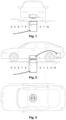
- the present invention consists in using a retractable terminal comprising the transmitter, located in the roadway, unfolding towards the floor of the electric vehicle (comprising the receiver) to be recharged, until it makes contact.
- This retractable terminal and the vehicle floor will be equipped with coils allowing the batteries to be recharged by induction using a universal process chosen by all vehicle manufacturers.
- the retractable terminal will be equipped with control electronics (7) allowing the transmitter to be brought closer to the receiver (2) and safety devices. This will allow the electrical energy to be transmitted to the vehicle batteries via an electronic box (5) and the power cable (4).
- the transmitter coils are integrated into the top of the retractable terminal.
- This terminal also includes a mechanical device allowing it to be raised and lowered, as well as a power cable (9) delivering energy from the electrical network.
- the charging mode can be carried out in direct or alternating current via the electronic box allowing you to choose the battery recharging speed.
- This solution has the advantage of offering a universal system compatible with all vehicle ground clearances and thus maximizing electrical efficiency to more than 95%.
- the receiver coil will be installed in the middle of the vehicle floor, thus facilitating the centering of the receiver and transmitter. This alignment will be controllable via an application that will be integrated into mobile phones or directly included in the vehicle interface when the terminal is in the rest position.
- This application will allow you to locate available terminals, to center the vehicle which can park forwards or backwards in a parking space, or on the right or left along a sidewalk (the receiver being already centered on the transmitter transversely).
- the application will also allow you to control the charge level and the charging time, to manage the height control of the terminal depending on the vehicle until the contact and to prohibit the starting of the vehicle if the terminal has not returned to its starting point, i.e. at zero level relative to the ground.
- the application will also manage data allowing charging to be billed based on the power requested and its duration, will integrate the user's banking information and will integrate a map indicating the terminals available near the vehicle.
- this terminal will be secured at several levels: the terminal will only be able to deploy if the centering indicates correct coupling, charging will only be able to begin if the terminal (transmitting part with an integrated winding) is in contact with the receiving part (integrated winding under the vehicle floor), and the vehicle will only be able to move if the terminal has completely returned to its initial position, i.e. at ground level.
Landscapes
- Engineering & Computer Science (AREA)
- Power Engineering (AREA)
- Mechanical Engineering (AREA)
- Transportation (AREA)
- Business, Economics & Management (AREA)
- Development Economics (AREA)
- Marketing (AREA)
- Finance (AREA)
- Economics (AREA)
- Strategic Management (AREA)
- Physics & Mathematics (AREA)
- General Business, Economics & Management (AREA)
- General Physics & Mathematics (AREA)
- Theoretical Computer Science (AREA)
- Accounting & Taxation (AREA)
- Computer Networks & Wireless Communication (AREA)
- Charge And Discharge Circuits For Batteries Or The Like (AREA)
- Electric Propulsion And Braking For Vehicles (AREA)
- Control Of Position, Course, Altitude, Or Attitude Of Moving Bodies (AREA)
Description
- La présente invention concerne un dispositif pour faciliter le rechargement des véhicules électriques par induction contrairement aux dispositifs actuels utilisant un câble et une prise de raccordement
- Les solutions de recharge à induction proposées pour les véhicules électriques sont basées sur des systèmes ayant une distance importante entre l'émetteur et le récepteur, soit une vingtaine de centimètres, ce qui implique d'utiliser des techniques hautes fréquences onéreuses et prioritaires à chaque marque de véhicules. Par ailleurs on constate également que les gardes au sol étant différentes en fonction des modèles au sein d'une même marque et que le problème de couplage électromagnétique étant directement proportionnel au carré de la distance et au centrage entre l'émetteur et le récepteur, tout ceci rend ces solutions de recharges onéreuses et difficilement utilisable de façon universelle.
-
WO 2011/151696 A2 divulgue un dispositif placé dans un parking ayant plusieurs emplacements pour recharger par induction les véhicules électriques s'y trouvant grâce à une borne rétractable qui est déplaçable vers les différents emplacements du parking. Une partie de commande incluse dans une installation fixe sur le bord du parking gère la routine de recharge des véhicules. Elle gère en particulier l'ordre dans lesquels les véhicules doivent être chargés et le déplacement de la borne rétractable vers les différents emplacements du parking, ainsi que son alignement avec le récepteur du véhicule électrique s'y trouvant, puis provoque la montée de la borne rétractable vers le récepteur du véhicule et sa descente, ainsi que la recharge proprement dite. Cette partie de commande envoie aussi des informations aux propriétaires des véhicules en les envoyant à des dispositifs d'affichage installés dans leur résidence. Quant au véhicule électrique, il est équipé d'un microcontrôleur pour transmettre un identifiant du véhicule et l'état de charge de ses batteries au dispositif de charge placé dans le parking via un dispositif de communication sans fil. -
WO 2018/076016 A1 décrit dans le contexte de la recharge des véhicules électriques une application mobile pouvant être intégrée à un véhicule électrique et fournissant une assistance au conducteur pour aligner le récepteur du véhicule par rapport à un émetteur d'une borne de recharge par induction qui est agencée de manière fixe dans le sol ou ailleurs sans possibilité de se déployer et se rétracter. A cette fin, l'application mobile affiche des informations d'alignement du véhicule électrique avec la borne de recharge. Elle permet aussi à l'utilisateur de lancer la recharge et d'afficher des informations relatives à la recharge telle que la progression de la charge, le temps de recharge et le coût de la recharge. Elle permet aussi de géolocaliser les bornes de recharge existant dans une région géographique. - L'invention quant à elle propose une application mobile ou intégrée dans un véhicule électrique, qui est prévue pour gérer une borne rétractable d'un dispositif pour recharger les batteries des véhicules électriques par induction, cette application étant définie dans la revendication 1. L'invention propose aussi conformément à la revendication 7 un dispositif pour recharger les batteries de véhicules électriques par induction, comprenant une borne rétractable prévue pour être placée dans une chaussée et qui est prévue pour être gérée par l'intermédiaire d'une telle application mobile ou intégrée dans le véhicule. Le dispositif peut être appliqué à la recharge des batteries de véhicules électriques de tous types, tous modèles, toutes marques. L'invention propose enfin conformément à la revendication 9 un système comprenant à la fois un tel dispositif pour recharger les batteries de véhicules électriques par induction et une telle application mobile ou intégrée dans un véhicule électrique. Les revendications dépendantes définissent des modes de réalisation préférés.
- Cette solution originale et innovante permettra de recharger facilement les batteries des véhicules électriques, automatiquement sans intervention manuelle du conducteur et dans un futur proche d'effectuer la recharge des batteries, des véhicules autonomes, sans intervention humaine.
- La présente invention consiste à utiliser une borne rétractable comprenant l'émetteur, se trouvant dans la chaussée, se dépliant vers le plancher du véhicule électrique (comprenant le récepteur) à recharger, jusqu'à son contact.
- Cette borne rétractable ainsi que le plancher du véhicule seront équipés de bobinages permettant la recharge des batteries par induction utilisant un procédé universel choisi par tous les constructeurs de véhicules. La borne rétractable sera équipée de l'électronique de contrôle (7) permettant de rapprocher l'émetteur jusqu'au récepteur (2) et des dispositifs de sécurité. Ceci permettra de transmettre l'énergie électrique aux batteries du véhicule par l'intermédiaire d'un boîtier électronique (5) et du câble d'alimentation (4). Les bobinages de l'émetteur sont intégrés au sommet de la borne rétractable.
- Cette borne inclut également un dispositif mécanique permettant la montée et la descente de celle-ci, ainsi qu'un câble d'alimentation (9) délivrant de l'énergie depuis le réseau électrique.
- Le mode de chargement pourra s'effectuer en courant continu ou alternatif par l'intermédiaire du boîtier électronique permettant de choisir la vitesse de rechargement des batteries.
- Cette solution permet de garantir un rendement optimum de la recharge des batteries par induction.
- Cette solution a l'avantage de proposer un système universel compatible avec toutes les gardes au sol des véhicules et ainsi de maximiser le rendement électrique à plus de 95%. La bobine réceptrice sera implantée au milieu du plancher du véhicule, permettant ainsi de faciliter le centrage du récepteur et de l'émetteur. Cet alignement sera contrôlable par l'intermédiaire d'une application qui sera intégrée dans les téléphones portables ou directement inclus dans l'interface des véhicules lorsque la borne est en position repos.
- Cette application permettra de localiser les bornes disponibles, de permettre le centrage du véhicule pouvant se garer en marche avant ou en marche arrière sur une place de parking, ou sur la droite ou la gauche le long d'un trottoir (le récepteur étant déjà centré sur l'émetteur en transversale).
- L'application permettra également de contrôler le niveau de charge et le temps de charge, de gérer le contrôle de la hauteur de la borne en fonction du véhicule jusqu'au contact et d'interdire le démarrage du véhicule si la borne n'est pas revenue à son point de départ soit au niveau zéro par rapport au sol.
- L'application gérera également les données permettant la facturation de la recharge en fonction de la puissance demandée et de la durée de celle-ci, intègrera les informations bancaires de l'utilisateur et intégrera une carte indiquant les bornes disponibles à proximité du véhicule.
- L'automatisation de cette borne sera sécurisée à plusieurs niveaux la borne ne pourra se déployer que si le centrage indique un couplage correct, la recharge ne pourra débuter que si la borne (partie émettrice ayant un bobinage intégré) se trouve en contact avec la partie réceptrice (bobinage intégré sous le planché du véhicule), et le véhicule ne pourra bouger que si la borne est complètement revenue à sa position initiale c'est-à-dire au niveau du sol.
- Cette solution permettra d'implanter ces bornes de recharge facilement dans tous les lieux publiques ou privés ainsi que dans des lieux classés, car celle-ci seront invisibles et impossible à vandaliser car aucun élément ne sera apparent en surface au niveau de la chaussée.
- Les dessins en annexes illustrent la simplicité de la solution et son efficacité évidente.
- Automatisme intégral, invisible au repos, adaptable à tous types de véhicules électriques rechargeables : voitures, camions, autocars, véhicules autonomes, ainsi que les deux roues, scooters, motos, système autonomes (Robots de livraison) etc...
Claims (9)
- Application mobile (14) ou intégrée dans un véhicule électrique (1), prévue pour gérer une borne rétractable (8) d'un dispositif pour recharger les batteries des véhicules électriques par induction, la borne rétractable (8) se trouvant dans une chaussée et intégrant la partie émettrice incluant le ou les bobinages (6) et l'électronique de contrôle (7) permettant de rapprocher cet émetteur jusqu'au récepteur (2) intégré sous le plancher du véhicule (1), permettant de transmettre l'énergie électrique aux batteries du véhicule (3) par l'intermédiaire d'un boîtier électronique (5) et du câble d'alimentation (4), la borne rétractable (8) incluant également un dispositif mécanique permettant la montée et la descente de celle-ci, ainsi qu'un câble d'alimentation (9) délivrant l'énergie depuis le réseau électrique,
l'application étant prévue pour :- contrôler la position du véhicule par rapport à la borne rétractable en position repos,- indiquer la qualité du couplage (12), le niveau de charge (13) et le temps de charge (11),- gérer le contrôle du déplacement en hauteur de la borne rétractable en fonction du véhicule jusqu'au contact avec la partie récepteur, et- interdire le démarrage du véhicule si la borne rétractable n'est pas revenue à son point de départ soit au niveau zéro par rapport au sol. - Application selon la revendication 1, laquelle est prévue pour intégrer des informations bancaires de l'utilisateur, permettant la facturation de l'énergie consommée.
- Application selon la revendication 1 ou 2, laquelle est prévue pour intégrer une carte indiquant les bornes disponibles à proximité du véhicule électrique.
- Dispositif pour recharger les batteries de véhicules électriques par induction, comprenant une borne rétractable (8) prévue pour être placée dans une chaussée, dans lequel :- la borne rétractable (8) intègre la partie émettrice incluant le ou les bobinages (6) et l'électronique de contrôle (7) permettant de rapprocher cet émetteur jusqu'au récepteur (2) intégré sous le plancher du véhicule (1), permettant de transmettre l'énergie électrique aux batteries du véhicule (3) par l'intermédiaire d'un boîtier électronique (5) et du câble d'alimentation (4),- la borne rétractable (8) inclut également un dispositif mécanique permettant la montée et la descente de celle-ci, ainsi qu'un câble d'alimentation (9) délivrant l'énergie depuis le réseau électrique, et- la borne rétractable (8) est prévue pour être gérée par l'intermédiaire d'une application mobile (14) ou intégrée dans le véhicule (1) selon l'une quelconque des revendications 1 à 3.
- Dispositif selon la revendication 4, dans lequel la borne rétractable (8) est prévue pour venir en contact avec le récepteur (2) fixé ou intégré sous le véhicule (1) et centré par rapport à celui-ci..
- Dispositif selon la revendication 4 ou 5, dans lequel les bobinages (6) sont intégrés au sommet de la borne rétractable (8).
- Dispositif selon l'une quelconque des revendications 4 à 6, dans lequel la borne rétractable (8) intègre également des dispositifs de sécurité inclus dans le boîtier électronique (7).
- Dispositif selon l'une des quelconques revendications 4 à 7, dans lequel l'application pour téléphone mobile ou intégré dans le véhicule est nécessaire et indispensable pour l'utilisation de la borne rétractable (8).
- Système, comprenant :- un dispositif pour recharger les batteries de véhicules électriques selon l'une quelconque des revendications 4 à 8, et- une application mobile (14) ou intégrée dans un véhicule électrique (1) selon l'une quelconque des revendications 1 à 3, laquelle est prévue pour gérer la borne rétractable (8) du dispositif pour recharger les batteries de véhicules électriques.
Applications Claiming Priority (2)
| Application Number | Priority Date | Filing Date | Title |
|---|---|---|---|
| FR1910027A FR3100490B1 (fr) | 2019-09-11 | 2019-09-11 | Dispositif de recharge de batteries de véhicules électriques par induction |
| PCT/FR2020/000228 WO2021048472A1 (fr) | 2019-09-11 | 2020-08-26 | Dispositif de recharge de batteries de véhicules électriques par induction |
Publications (3)
| Publication Number | Publication Date |
|---|---|
| EP4028280A1 EP4028280A1 (fr) | 2022-07-20 |
| EP4028280B1 true EP4028280B1 (fr) | 2024-11-27 |
| EP4028280C0 EP4028280C0 (fr) | 2024-11-27 |
Family
ID=69699942
Family Applications (1)
| Application Number | Title | Priority Date | Filing Date |
|---|---|---|---|
| EP20788847.0A Active EP4028280B1 (fr) | 2019-09-11 | 2020-08-26 | Dispositif de recharge de batteries de véhicules électriques par induction |
Country Status (7)
| Country | Link |
|---|---|
| US (1) | US20220324337A1 (fr) |
| EP (1) | EP4028280B1 (fr) |
| CN (1) | CN114728597B (fr) |
| CA (1) | CA3150694A1 (fr) |
| ES (1) | ES3009887T3 (fr) |
| FR (1) | FR3100490B1 (fr) |
| WO (1) | WO2021048472A1 (fr) |
Families Citing this family (1)
| Publication number | Priority date | Publication date | Assignee | Title |
|---|---|---|---|---|
| FR3165821A1 (fr) | 2024-09-04 | 2026-03-06 | Upandcharge | dispositif de recharge par induction des batteries électriques rechargeables d’un véhicule électrique |
Citations (1)
| Publication number | Priority date | Publication date | Assignee | Title |
|---|---|---|---|---|
| EP1061631A1 (fr) * | 1996-01-30 | 2000-12-20 | Sumitomo Wiring Systems, Ltd. | Système de connexion et méthode de connexion pour un véhicule automobile électrique |
Family Cites Families (24)
| Publication number | Priority date | Publication date | Assignee | Title |
|---|---|---|---|---|
| US7859219B2 (en) * | 2007-02-07 | 2010-12-28 | David M Harris | Disconnect for a charging unit for an electric vehicle |
| JP4453741B2 (ja) * | 2007-10-25 | 2010-04-21 | トヨタ自動車株式会社 | 電動車両および車両用給電装置 |
| GB2475703A (en) * | 2009-11-26 | 2011-06-01 | Sylvan Ascent Inc | Electric vehicle charging station and charge receiving arrangement for a vehicle |
| CN102118069B (zh) * | 2009-12-31 | 2014-12-17 | 上海汽车集团股份有限公司 | 高效率的非接触式充电系统和利用该系统充电的车辆 |
| JP5604181B2 (ja) * | 2010-05-31 | 2014-10-08 | トヨタホーム株式会社 | 充電装置 |
| CN101917040B (zh) * | 2010-08-16 | 2016-04-20 | 倪既民 | 地埋式车辆充电装置 |
| GB201121938D0 (en) * | 2011-12-21 | 2012-02-01 | Dames Andrew N | Supply of grid power to moving vehicles |
| US9555716B2 (en) * | 2012-03-21 | 2017-01-31 | Ford Global Technologies, Llc | Automotive vehicle charge system |
| WO2014029439A1 (fr) * | 2012-08-23 | 2014-02-27 | Siemens Aktiengesellschaft | Dispositif de charge par induction |
| US9434263B2 (en) * | 2012-09-05 | 2016-09-06 | Lear Corporation | Multi-mode battery charger |
| GB201403547D0 (en) * | 2014-02-28 | 2014-04-16 | Bombardier Transp Gmbh | Inductive power transfer pad, system for inductive power transfer and method of operating an inductive power transfer pad |
| US9505314B2 (en) * | 2013-08-09 | 2016-11-29 | Qualcomm Incorporated | Systems, methods, and apparatus related to detecting and identifying electric vehicle and charging station |
| CA2924500C (fr) * | 2013-09-30 | 2024-02-06 | Recargo, Inc. | Faciliter un acces a un reseau de recharge pour vehicules electriques |
| DE102014200290A1 (de) * | 2014-01-10 | 2015-07-16 | Robert Bosch Gmbh | Elektrische Ladevorrichtung, elektrische Anschlussvorrichtung, System und Verfahren zum Laden einer Batterie eines Fahrzeugs |
| US9527403B2 (en) * | 2014-04-29 | 2016-12-27 | Tesla Motors, Inc. | Charging station providing thermal conditioning of electric vehicle during charging session |
| US20150336462A1 (en) * | 2014-05-21 | 2015-11-26 | Ford Global Technologies, Llc | Sonic triangulation method for locating vehicles for hands-free electric vehicle charging |
| CN105069919B (zh) * | 2015-08-11 | 2018-07-20 | 万帮充电设备有限公司 | 智能充电管理的方法 |
| US20170140349A1 (en) * | 2015-11-13 | 2017-05-18 | NextEv USA, Inc. | Vehicle Group Charging System and Method of Use |
| US9873408B2 (en) * | 2016-05-11 | 2018-01-23 | Peter D. Capizzo | Device for refueling, exchanging, and charging power sources on remote controlled vehicles, UAVs, drones, or any type of robotic vehicle or machine with mobility |
| US10286799B2 (en) * | 2016-08-23 | 2019-05-14 | GM Global Technology Operations LLC | Hands-free conductive battery charger for an electric vehicle |
| US10369894B2 (en) * | 2016-10-21 | 2019-08-06 | Hevo, Inc. | Parking alignment sequence for wirelessly charging an electric vehicle |
| GB2567629B (en) * | 2017-10-13 | 2022-09-21 | Urban Electric Networks Ltd | Retractable charging station |
| GB2573748B (en) * | 2018-05-08 | 2023-01-04 | Urban Electric Networks Ltd | Electric vehicle charging station |
| CN110027417A (zh) * | 2019-05-07 | 2019-07-19 | 青岛鲁渝能源科技有限公司 | 无线充电装置、系统及无线充电控制方法 |
-
2019
- 2019-09-11 FR FR1910027A patent/FR3100490B1/fr active Active
-
2020
- 2020-08-26 EP EP20788847.0A patent/EP4028280B1/fr active Active
- 2020-08-26 WO PCT/FR2020/000228 patent/WO2021048472A1/fr not_active Ceased
- 2020-08-26 US US17/641,508 patent/US20220324337A1/en active Pending
- 2020-08-26 CA CA3150694A patent/CA3150694A1/fr active Pending
- 2020-08-26 CN CN202080080028.4A patent/CN114728597B/zh active Active
- 2020-08-26 ES ES20788847T patent/ES3009887T3/es active Active
Patent Citations (1)
| Publication number | Priority date | Publication date | Assignee | Title |
|---|---|---|---|---|
| EP1061631A1 (fr) * | 1996-01-30 | 2000-12-20 | Sumitomo Wiring Systems, Ltd. | Système de connexion et méthode de connexion pour un véhicule automobile électrique |
Also Published As
| Publication number | Publication date |
|---|---|
| FR3100490B1 (fr) | 2021-09-24 |
| CN114728597A (zh) | 2022-07-08 |
| WO2021048472A1 (fr) | 2021-03-18 |
| CN114728597B (zh) | 2025-09-23 |
| FR3100490A1 (fr) | 2021-03-12 |
| US20220324337A1 (en) | 2022-10-13 |
| EP4028280A1 (fr) | 2022-07-20 |
| EP4028280C0 (fr) | 2024-11-27 |
| CA3150694A1 (fr) | 2021-03-18 |
| ES3009887T3 (en) | 2025-03-31 |
Similar Documents
| Publication | Publication Date | Title |
|---|---|---|
| US11511635B2 (en) | Electric power system | |
| US8890475B1 (en) | Automobile charging and communications station | |
| US9333866B2 (en) | Charging device and charging method with float-mounted charging unit | |
| US11198373B2 (en) | Method for operating a charging device | |
| US20120233062A1 (en) | Method and process for an electric vehicle charging system to automatically engage the charging apparatus of an electric vehicle | |
| US11413977B2 (en) | Charging assembly for electric vehicle | |
| EP4028280B1 (fr) | Dispositif de recharge de batteries de véhicules électriques par induction | |
| FR2968611A1 (fr) | Portion de chaussee avec boucle a induction pour vehicules hybrides ou electriques | |
| EP3377343B1 (fr) | Procede et systeme de chauffage d'un habitacle d'un vehicule electrique | |
| WO2015160937A1 (fr) | Système mobile pour la génération, le stockage et la fourniture d'énergie électrique | |
| EP3888227B1 (fr) | Procédé de recharge par induction d'une batterie d'un véhicule garé, via un boîtier se déplaçant par rapport à une référence | |
| FR3089892A1 (fr) | Système pour la charge/recharge de moyens de stockage d’énergie d’un véhicule à moteur électrique | |
| FR3078836A1 (fr) | Systeme de rechargement electrique multimodal pour un vehicule electrique, et vehicule electrique equipe d'un tel systeme | |
| FR3066052A1 (fr) | Dispositif de recharge par induction de batterie(s) d'un vehicule, a prises de courant multiples pour un boitier mobile | |
| FR3062607A1 (fr) | Dispositif mobile de recharge par induction de batterie(s) d'un vehicule, a deplacements autonomes | |
| FR3069813B1 (fr) | Boitier mobile autonome a cable d’alimentation desenroule par ses rotations, pour recharger par induction une batterie de vehicule | |
| FR3003815A1 (fr) | Procede pour la charge par induction d'une batterie electrique d'un vehicule automobile, station de charge, vehicule automobile et borne de charge associes | |
| FR3056349A1 (fr) | Dispositif mobile de recharge par induction de batterie(s) d'un vehicule | |
| TW201710120A (zh) | 無線充電板與無線充電系統 | |
| FR3084025A1 (fr) | Boitier mobile autonome a eclairement de son environnement, pour recharger par induction une batterie de vehicule | |
| FR2996376A1 (fr) | Procede de charge d'une batterie d'accumulateurs d'un vehicule automobile | |
| FR3070329A1 (fr) | Procede d’assistance a la recharge par induction d’une batterie d’un vehicule venant se garer sur un emplacement | |
| KR20140145683A (ko) | 전기 충전 장치 및 그 제어 방법 | |
| WO2012042179A2 (fr) | Charge sans contact d'une batterie de vehicule automobile | |
| FR3152252A1 (fr) | Procede de depannage de rechargement de vehicules automobiles electriques ou hybrides |
Legal Events
| Date | Code | Title | Description |
|---|---|---|---|
| STAA | Information on the status of an ep patent application or granted ep patent |
Free format text: STATUS: UNKNOWN |
|
| STAA | Information on the status of an ep patent application or granted ep patent |
Free format text: STATUS: THE INTERNATIONAL PUBLICATION HAS BEEN MADE |
|
| PUAI | Public reference made under article 153(3) epc to a published international application that has entered the european phase |
Free format text: ORIGINAL CODE: 0009012 |
|
| STAA | Information on the status of an ep patent application or granted ep patent |
Free format text: STATUS: REQUEST FOR EXAMINATION WAS MADE |
|
| 17P | Request for examination filed |
Effective date: 20220330 |
|
| AK | Designated contracting states |
Kind code of ref document: A1 Designated state(s): AL AT BE BG CH CY CZ DE DK EE ES FI FR GB GR HR HU IE IS IT LI LT LU LV MC MK MT NL NO PL PT RO RS SE SI SK SM TR |
|
| DAV | Request for validation of the european patent (deleted) | ||
| DAX | Request for extension of the european patent (deleted) | ||
| GRAP | Despatch of communication of intention to grant a patent |
Free format text: ORIGINAL CODE: EPIDOSNIGR1 |
|
| STAA | Information on the status of an ep patent application or granted ep patent |
Free format text: STATUS: GRANT OF PATENT IS INTENDED |
|
| INTG | Intention to grant announced |
Effective date: 20240620 |
|
| GRAS | Grant fee paid |
Free format text: ORIGINAL CODE: EPIDOSNIGR3 |
|
| GRAA | (expected) grant |
Free format text: ORIGINAL CODE: 0009210 |
|
| STAA | Information on the status of an ep patent application or granted ep patent |
Free format text: STATUS: THE PATENT HAS BEEN GRANTED |
|
| AK | Designated contracting states |
Kind code of ref document: B1 Designated state(s): AL AT BE BG CH CY CZ DE DK EE ES FI FR GB GR HR HU IE IS IT LI LT LU LV MC MK MT NL NO PL PT RO RS SE SI SK SM TR |
|
| REG | Reference to a national code |
Ref country code: GB Ref legal event code: FG4D Free format text: NOT ENGLISH |
|
| REG | Reference to a national code |
Ref country code: CH Ref legal event code: EP |
|
| REG | Reference to a national code |
Ref country code: IE Ref legal event code: FG4D Free format text: LANGUAGE OF EP DOCUMENT: FRENCH |
|
| REG | Reference to a national code |
Ref country code: DE Ref legal event code: R096 Ref document number: 602020042130 Country of ref document: DE |
|
| U01 | Request for unitary effect filed |
Effective date: 20241216 |
|
| U07 | Unitary effect registered |
Designated state(s): AT BE BG DE DK EE FI FR IT LT LU LV MT NL PT RO SE SI Effective date: 20250110 |
|
| REG | Reference to a national code |
Ref country code: ES Ref legal event code: FG2A Ref document number: 3009887 Country of ref document: ES Kind code of ref document: T3 Effective date: 20250331 |
|
| PG25 | Lapsed in a contracting state [announced via postgrant information from national office to epo] |
Ref country code: HR Free format text: LAPSE BECAUSE OF FAILURE TO SUBMIT A TRANSLATION OF THE DESCRIPTION OR TO PAY THE FEE WITHIN THE PRESCRIBED TIME-LIMIT Effective date: 20241127 Ref country code: IS Free format text: LAPSE BECAUSE OF FAILURE TO SUBMIT A TRANSLATION OF THE DESCRIPTION OR TO PAY THE FEE WITHIN THE PRESCRIBED TIME-LIMIT Effective date: 20250327 |
|
| PG25 | Lapsed in a contracting state [announced via postgrant information from national office to epo] |
Ref country code: NO Free format text: LAPSE BECAUSE OF FAILURE TO SUBMIT A TRANSLATION OF THE DESCRIPTION OR TO PAY THE FEE WITHIN THE PRESCRIBED TIME-LIMIT Effective date: 20250227 |
|
| PG25 | Lapsed in a contracting state [announced via postgrant information from national office to epo] |
Ref country code: GR Free format text: LAPSE BECAUSE OF FAILURE TO SUBMIT A TRANSLATION OF THE DESCRIPTION OR TO PAY THE FEE WITHIN THE PRESCRIBED TIME-LIMIT Effective date: 20250228 |
|
| PG25 | Lapsed in a contracting state [announced via postgrant information from national office to epo] |
Ref country code: PL Free format text: LAPSE BECAUSE OF FAILURE TO SUBMIT A TRANSLATION OF THE DESCRIPTION OR TO PAY THE FEE WITHIN THE PRESCRIBED TIME-LIMIT Effective date: 20241127 |
|
| PG25 | Lapsed in a contracting state [announced via postgrant information from national office to epo] |
Ref country code: RS Free format text: LAPSE BECAUSE OF FAILURE TO SUBMIT A TRANSLATION OF THE DESCRIPTION OR TO PAY THE FEE WITHIN THE PRESCRIBED TIME-LIMIT Effective date: 20250227 |
|
| PG25 | Lapsed in a contracting state [announced via postgrant information from national office to epo] |
Ref country code: SM Free format text: LAPSE BECAUSE OF FAILURE TO SUBMIT A TRANSLATION OF THE DESCRIPTION OR TO PAY THE FEE WITHIN THE PRESCRIBED TIME-LIMIT Effective date: 20241127 |
|
| PG25 | Lapsed in a contracting state [announced via postgrant information from national office to epo] |
Ref country code: SK Free format text: LAPSE BECAUSE OF FAILURE TO SUBMIT A TRANSLATION OF THE DESCRIPTION OR TO PAY THE FEE WITHIN THE PRESCRIBED TIME-LIMIT Effective date: 20241127 |
|
| PG25 | Lapsed in a contracting state [announced via postgrant information from national office to epo] |
Ref country code: CZ Free format text: LAPSE BECAUSE OF FAILURE TO SUBMIT A TRANSLATION OF THE DESCRIPTION OR TO PAY THE FEE WITHIN THE PRESCRIBED TIME-LIMIT Effective date: 20241127 |
|
| PLBE | No opposition filed within time limit |
Free format text: ORIGINAL CODE: 0009261 |
|
| STAA | Information on the status of an ep patent application or granted ep patent |
Free format text: STATUS: NO OPPOSITION FILED WITHIN TIME LIMIT |
|
| REG | Reference to a national code |
Ref country code: CH Ref legal event code: L10 Free format text: ST27 STATUS EVENT CODE: U-0-0-L10-L00 (AS PROVIDED BY THE NATIONAL OFFICE) Effective date: 20251008 |
|
| U20 | Renewal fee for the european patent with unitary effect paid |
Year of fee payment: 6 Effective date: 20250901 |
|
| PGFP | Annual fee paid to national office [announced via postgrant information from national office to epo] |
Ref country code: ES Payment date: 20250909 Year of fee payment: 6 |
|
| PGFP | Annual fee paid to national office [announced via postgrant information from national office to epo] |
Ref country code: GB Payment date: 20250801 Year of fee payment: 6 |
|
| 26N | No opposition filed |
Effective date: 20250828 |
|
| REG | Reference to a national code |
Ref country code: CH Ref legal event code: H13 Free format text: ST27 STATUS EVENT CODE: U-0-0-H10-H13 (AS PROVIDED BY THE NATIONAL OFFICE) Effective date: 20260324 |
|
| PG25 | Lapsed in a contracting state [announced via postgrant information from national office to epo] |
Ref country code: MC Free format text: LAPSE BECAUSE OF FAILURE TO SUBMIT A TRANSLATION OF THE DESCRIPTION OR TO PAY THE FEE WITHIN THE PRESCRIBED TIME-LIMIT Effective date: 20241127 |
|
| REG | Reference to a national code |
Ref country code: CH Ref legal event code: R17 Free format text: ST27 STATUS EVENT CODE: U-0-0-R10-R17 (AS PROVIDED BY THE NATIONAL OFFICE) Effective date: 20260410 |
|
| REG | Reference to a national code |
Ref country code: CH Ref legal event code: K11 Free format text: ST27 STATUS EVENT CODE: U-0-0-K10-K11 (AS PROVIDED BY THE NATIONAL OFFICE) Effective date: 20260413 Ref country code: CH Ref legal event code: U11 Free format text: ST27 STATUS EVENT CODE: U-0-0-U10-U11 (AS PROVIDED BY THE NATIONAL OFFICE) Effective date: 20260413 |
|
| PG25 | Lapsed in a contracting state [announced via postgrant information from national office to epo] |
Ref country code: CH Free format text: LAPSE BECAUSE OF NON-PAYMENT OF DUE FEES Effective date: 20250831 |