EP4028176B1 - Verfahren zur ermittlung des zusetzens sowie der zusetzenmerkmale einer beschichtungsvorrichtung, beschichtungsvorrichtung, kalibrierungssystem und industrieroboter - Google Patents
Verfahren zur ermittlung des zusetzens sowie der zusetzenmerkmale einer beschichtungsvorrichtung, beschichtungsvorrichtung, kalibrierungssystem und industrieroboter Download PDFInfo
- Publication number
- EP4028176B1 EP4028176B1 EP19768756.9A EP19768756A EP4028176B1 EP 4028176 B1 EP4028176 B1 EP 4028176B1 EP 19768756 A EP19768756 A EP 19768756A EP 4028176 B1 EP4028176 B1 EP 4028176B1
- Authority
- EP
- European Patent Office
- Prior art keywords
- discharge holes
- clogging
- flow
- air pressure
- air
- Prior art date
- Legal status (The legal status is an assumption and is not a legal conclusion. Google has not performed a legal analysis and makes no representation as to the accuracy of the status listed.)
- Active
Links
Images


Classifications
-
- G—PHYSICS
- G01—MEASURING; TESTING
- G01F—MEASURING VOLUME, VOLUME FLOW, MASS FLOW OR LIQUID LEVEL; METERING BY VOLUME
- G01F1/00—Measuring the volume flow or mass flow of fluid or fluent solid material wherein the fluid passes through a meter in a continuous flow
- G01F1/05—Measuring the volume flow or mass flow of fluid or fluent solid material wherein the fluid passes through a meter in a continuous flow by using mechanical effects
- G01F1/34—Measuring the volume flow or mass flow of fluid or fluent solid material wherein the fluid passes through a meter in a continuous flow by using mechanical effects by measuring pressure or differential pressure
-
- B—PERFORMING OPERATIONS; TRANSPORTING
- B05—SPRAYING OR ATOMISING IN GENERAL; APPLYING FLUENT MATERIALS TO SURFACES, IN GENERAL
- B05B—SPRAYING APPARATUS; ATOMISING APPARATUS; NOZZLES
- B05B15/00—Details of spraying plant or spraying apparatus not otherwise provided for; Accessories
- B05B15/50—Arrangements for cleaning; Arrangements for preventing deposits, drying-out or blockage; Arrangements for detecting improper discharge caused by the presence of foreign matter
-
- B—PERFORMING OPERATIONS; TRANSPORTING
- B25—HAND TOOLS; PORTABLE POWER-DRIVEN TOOLS; MANIPULATORS
- B25J—MANIPULATORS; CHAMBERS PROVIDED WITH MANIPULATION DEVICES
- B25J11/00—Manipulators not otherwise provided for
- B25J11/0075—Manipulators for painting or coating
-
- B—PERFORMING OPERATIONS; TRANSPORTING
- B05—SPRAYING OR ATOMISING IN GENERAL; APPLYING FLUENT MATERIALS TO SURFACES, IN GENERAL
- B05B—SPRAYING APPARATUS; ATOMISING APPARATUS; NOZZLES
- B05B12/00—Arrangements for controlling delivery; Arrangements for controlling the spray area
- B05B12/004—Arrangements for controlling delivery; Arrangements for controlling the spray area comprising sensors for monitoring the delivery, e.g. by displaying the sensed value or generating an alarm
-
- B—PERFORMING OPERATIONS; TRANSPORTING
- B05—SPRAYING OR ATOMISING IN GENERAL; APPLYING FLUENT MATERIALS TO SURFACES, IN GENERAL
- B05B—SPRAYING APPARATUS; ATOMISING APPARATUS; NOZZLES
- B05B13/00—Machines or plants for applying liquids or other fluent materials to surfaces of objects or other work by spraying, not covered by groups B05B1/00 - B05B11/00
- B05B13/02—Means for supporting work; Arrangement or mounting of spray heads; Adaptation or arrangement of means for feeding work
- B05B13/04—Means for supporting work; Arrangement or mounting of spray heads; Adaptation or arrangement of means for feeding work the spray heads being moved during spraying operation
- B05B13/0447—Installation or apparatus for applying liquid or other fluent material to conveyed separate articles
- B05B13/0452—Installation or apparatus for applying liquid or other fluent material to conveyed separate articles the objects being vehicle components, e.g. vehicle bodies
-
- B—PERFORMING OPERATIONS; TRANSPORTING
- B05—SPRAYING OR ATOMISING IN GENERAL; APPLYING FLUENT MATERIALS TO SURFACES, IN GENERAL
- B05B—SPRAYING APPARATUS; ATOMISING APPARATUS; NOZZLES
- B05B3/00—Spraying or sprinkling apparatus with moving outlet elements or moving deflecting elements
- B05B3/02—Spraying or sprinkling apparatus with moving outlet elements or moving deflecting elements with rotating elements
- B05B3/10—Spraying or sprinkling apparatus with moving outlet elements or moving deflecting elements with rotating elements discharging over substantially the whole periphery of the rotating member
- B05B3/1092—Means for supplying shaping gas
Definitions
- the present disclosure generally relates to apparatuses for applying a coating medium to an object.
- a method of determining a degree of clogging of discharge holes of an apparatus for applying a coating medium to an object, an apparatus for applying a coating medium to an object, a calibration system comprising the apparatus and a blocking device, an industrial robot comprising the apparatus, and a method of determining clogging characteristics of an apparatus for applying a coating medium to an object are provided.
- the coating medium may be atomized by a rotary bell atomizer and applied to the object by means of shaping air and electrostatic charging of the coating medium.
- Various types of liquid based coating mediums, such as paint or varnish, may be applied to an object in this way.
- a controlled and uniform shaping air flow is important to obtain a stable and good application of the coating medium.
- the shaping air is typically dispensed through a plurality of discharge holes in a shaping air ring. If these discharge holes start to be clogged, e.g. by paint particles, the coating medium application performance will be deteriorated. Traditional ways of dealing with this problem is by manual inspection and/or by excessive use of solvent during cleaning to be on the "safe side".
- the method includes determining a target rotational speed, a target air flow rate, a target torque, and a target electrostatic current, and measuring an operating rotational speed, an operating air flow rate, an operating torque, and an operating electrostatic current.
- the method includes detecting at least one of a first condition in which the operating rotational speed differs from the target rotational speed, a second condition in which the operating air flow rate differs from the target air flow rate, a third condition in which the operating torque differs from the target torque, and a fourth condition in which the operating electrostatic current differs from the target electrostatic current.
- JP2007-066650A discloses a pattern correction device.
- JPH08-155347A discloses a rotary atomizing electrostatic coating device.
- curves describing a relationship between shaping air flow and required output air pressure to achieve that flow may be used to see a deviation between a calibrated curve and a dynamic curve and issue a warning about possible issues with shaping air, including clogging.
- this method is a crude method and does not allow a small amount of clogging to be detected. Furthermore, this method does not distinguish between clogging, and e.g. a temporarily pinched hose.
- One object of the present disclosure is to provide an accurate, simple and/or cost-effective method of determining a degree of clogging of discharge holes of an apparatus for applying a coating medium to an object.
- a further object of the present disclosure is to provide a method of determining a degree of clogging of discharge holes of an apparatus for applying a coating medium to an object, which method allows low levels of clogging to be detected.
- a still further object of the present disclosure is to provide a method of determining a degree of clogging of discharge holes of an apparatus for applying a coating medium to an object, which method solves several or all the foregoing objects in combination.
- a still further object of the present disclosure is to provide a method of determining a degree of clogging of discharge holes of an apparatus for applying a coating medium to an object, which method can distinguish between clogging and a passing anomaly, e.g. a pinched hose.
- a still further object of the present disclosure is to provide an apparatus for applying a coating medium to an object, which apparatus solves one, several or all the foregoing objects.
- a still further object of the present disclosure is to provide a calibration system solving one, several or all the foregoing objects.
- a still further object of the present disclosure is to provide an industrial robot solving one, several or all the foregoing objects.
- a still further object of the present disclosure is to provide a method of determining clogging characteristics of an apparatus for applying a coating medium to an object, which method solves one, several or all the foregoing objects.
- a method of determining a degree of clogging of discharge holes of an apparatus for applying a coating medium to an object comprising conducting shaping air through the discharge holes; determining an output air pressure between an air flow regulator of the apparatus and the discharge holes, the air flow regulator being arranged to regulate a flow of the shaping air; and determining a degree of clogging of the discharge holes based on the output air pressure.
- the method is based on the realization that a degree of clogging of the discharge holes can be determined based on the output air pressure.
- the method enables a reduction or elimination of waste of coating medium due to anomalous spray patterns arising out of clogged discharge holes.
- the method enables low levels of clogging to be accurately detected.
- the method also reduces false positive warnings that is a problem with the solution above, i.e. based on curves describing a relationship between shaping air flow and required output air pressure to achieve that flow.
- the method enables a reduced use of solvent for cleaning the apparatus and a reduced need for manual inspection. Thus, the method is cost-effective.
- the method may be carried out continuously or at selected intervals during operation of the apparatus. An operator can thereby be informed of the degree of clogging. If the degree of clogging exceeds a certain value, a warning may be issued and/or an automatic cleaning process may be initiated.
- the air flow regulator may be arranged to maintain a constant air flow, e.g. by means of a regulation loop.
- the discharge holes may be provided in a shaping air ring of the apparatus.
- the shaping air is for atomizing the coating medium.
- the method may further comprise conducting the coating medium through a coating medium outlet of the apparatus, e.g. in a rotating deflecting element.
- the apparatus may comprise a bell atomizer having a rotatable bell cup and the discharge holes may be shaping air nozzles provided in a shaping air ring of the bell atomizer.
- the present disclosure mainly describes the apparatus as comprising bell atomizer, the method is also applicable on other types of apparatuses for applying a coating medium to an object by means of shaping air, such as an apparatus comprising a paint gun operating with shaping air.
- an apparatus for applying a coating medium to an object may alternatively be referred to as a coating medium apparatus.
- the coating medium may for example be paint or varnish.
- the method may further comprise determining the degree of clogging based on flow data indicative of the flow.
- the flow data may for example be a target flow or a measured flow of the conducted air.
- the method may further comprise measuring the flow between the air flow regulator and the discharge holes and determining the flow data based on the measured flow. In this case, an actual or measured flow is thus used as the flow data.
- the output air pressure is determined by means of an output air pressure sensor.
- the output air pressure sensor may be arranged fluidly between the air flow regulator and the discharge holes, e.g. on an output air channel upstream of a branching point where the output air channel branches to the discharge holes.
- the degree of clogging may be determined as a percentage of clogging.
- the percentage of clogging may be determined using an equation and/or machine learning.
- the degree of clogging may be determined independently of an input air pressure of the shaping air upstream of the air flow regulator.
- the input air pressure may alternatively be referred to as a supply pressure.
- the output air pressure may alternatively be referred to as an internal pressure.
- the degree of clogging may be determined based on an equation.
- the equation may constitute a model of the apparatus.
- the equation may be a first order equation.
- the equation may comprise a scaling factor dependent on the flow.
- the equation may comprise an offset term dependent on the flow.
- the only variables of the equation may be the flow and the determined output air pressure.
- the method may further comprise filtering out false positives.
- the output air pressure may be monitored over time and temporal restrictions of the shaping air flow may be classified as hose pinching, while a gradual restriction buildup over time may be classified as clogging of the discharge holes.
- an apparatus for applying a coating medium to an object according to claim 10 comprising a plurality of discharge holes for shaping air; an air flow regulator arranged to regulate a flow of the shaping air to the discharge holes; and an output air pressure sensor arranged fluidly between the air flow regulator and the discharge holes and arranged to determine an output air pressure.
- the apparatus further comprises a control system configured to determine a degree of clogging of the discharge holes based on the output air pressure determined by the output air pressure sensor.
- the control system may further be configured to determine the degree of clogging based on flow data indicative of the flow.
- the apparatus may further comprise an air flow sensor arranged fluidly between the air flow regulator and the discharge holes and arranged to measure the flow between the air flow regulator and the discharge holes. The flow data may then be determined based on the measured flow.
- a control system for determining a degree of clogging of discharge holes of an apparatus for applying a coating medium to an object
- the control unit comprising a data processing device and a memory having a computer program stored thereon, the computer program comprising program code which, when executed by the data processing device, causes the data processing device to perform the steps of receiving a pressure signal indicative of an output air pressure of air conducted through the discharge holes at a point fluidly between an air flow regulator of the apparatus and the discharge holes, the air flow regulator being arranged to regulate the flow of the air; and determining a degree of clogging of the discharge holes based on the output air pressure.
- the apparatus comprises an atomizer having a rotatable deflecting element downstream of the discharge holes, such as a bell atomizer comprising a rotatable bell cup.
- an industrial robot according to claim 13.
- the industrial robot comprises an apparatus according to the present disclosure or a calibration system according to the present disclosure.
- a method of determining clogging characteristics of an apparatus for applying a coating medium to an object comprising conducting shaping air through discharge holes of the apparatus with a first parameter setting, the first parameter setting comprising flow data indicative of a flow of the shaping air, and clogging data indicative of a degree of clogging of the discharge holes; determining a first output air pressure between an air flow regulator of the apparatus and the discharge holes for the first parameter setting, the air flow regulator being arranged to regulate the flow; conducting shaping air through the discharge holes with a second parameter setting where at least one of the flow data and the clogging data is different from the first parameter setting; determining a second output air pressure between the air flow regulator and the discharge holes for the second parameter setting; and determining a relationship between a degree of clogging of the discharge holes and the output air pressure based on the flow data of the first and second parameter settings, the clogging data of the first and second parameter settings, the first output air pressure and the second output air pressure.
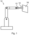
- the apparatus 12 comprises a flexible air hose 22 and a flexible coating medium hose 24. Pressurized air is led from a compressor 26 to the apparatus 12 through the air hose 22.
- the apparatus 12 further comprises a pump 28.
- the pump 28 receives pressurized coating medium from a reservoir 30 to the apparatus 12 through the coating medium hose 24.
- the compressor 26 and the reservoir 30 are arranged outside the apparatus 12.
- the compressor 26 may provide pressurized air to several robots 10. Thus, the available pressure from the compressor 26 is typically substantially higher than what is needed by the apparatus 12.
- the apparatus 12 further comprises a turbine 40.
- the turbine 40 is arranged to be rotated by a turbine air flow to rotate the bell cup 20.
- the turbine air flow may be a flow separate from the shaping air.
- the bell atomizer 18 of this example comprises the turbine 40, the shaping air ring 36, the discharge holes 34 and the bell cup 20.
- the bell atomizer 18 is arranged at the distal end of the manipulator of the robot 10.
- the remaining parts of the apparatus 12 may be arranged in other sections of the robot 10 and/or outside the robot 10.
- the apparatus 12 further comprises a control system 42.
- the control system 42 comprises a data processing device 44 and a memory 46 having a computer program stored thereon.
- the computer program comprises program code which, when executed by the data processing device 44, causes the data processing device 44 to perform various steps, or command performance of various steps, according to the present disclosure.
- the apparatus 12 further comprises an input air pressure sensor 48 for measuring an input air pressure of the shaping air.
- the input air pressure sensor 48 is arranged upstream of the air flow regulator 32, between the compressor 26 and the air flow regulator 32.
- the input air pressure sensor 48 is in signal communication with the control system 42.
- the input air pressure measured by the input air pressure sensor 48 may be used to ensure a sufficient supply pressure to the air flow regulator 32.
- the apparatus 12 further comprises an output air pressure sensor 50 for measuring an output air pressure of the shaping air.
- the output air pressure sensor 50 is arranged downstream of the air flow regulator 32, between the air flow regulator 32 and the discharge holes 34. As shown in Fig. 2 , the output air pressure sensor 50 is arranged on an output air channel upstream of a branching point 52 where the output air channel branches to the discharge holes 34.
- the output air pressure sensor 50 is in signal communication with the control system 42.
- the apparatus 12 further comprises an air flow sensor 54 for measuring the flow of the shaping air.
- the air flow sensor 54 is arranged downstream of the air flow regulator 32, between the air flow regulator 32 and the discharge holes 34. As shown in Fig. 2 , also the air flow regulator 32 is arranged on the output air channel upstream of the branching point 52.
- the air flow sensor 54 is in signal communication with the control system 42.
- the output air pressure sensor 50 is arranged between the air flow regulator 32 and the air flow sensor 54.
- the air flow sensor 54 may be arranged between the air flow regulator 32 and the output air pressure sensor 50.
- the apparatus 12 further comprises an input coating medium pressure sensor 56 for measuring an input coating medium pressure.
- the input coating medium pressure sensor 56 is arranged upstream of the pump 28, between the reservoir 30 and the pump 28.
- the input coating medium pressure sensor 56 is in signal communication with the control system 42.
- the apparatus 12 further comprises an output coating medium pressure sensor 58 for measuring an output coating medium pressure.
- the output coating medium pressure sensor 58 is arranged downstream of the pump 28, between the pump 28 and the coating medium outlet 38.
- pressurized air from the compressor 26 is controlled by the air flow regulator 32 to form shaping air.
- the shaping air exits through the discharge holes 34.
- Rotation of the turbine 40 causes the bell cup 20 to rotate.
- the coating medium from the reservoir 30 is conveyed by the pump 28 to the coating medium outlet 38. Due to the rotation of the bell cup 20, the coating medium flows from the coating medium outlet 38 to the front edge of the rotating bell cup 20.
- the shaping air from the discharge holes 34 is deflected by the bell cup 20, forms a flow of atomizing air, and propels coating medium droplets forward into a mist. The coating medium is thereby atomized.
- control system 42 reads sensor values from the input air pressure sensor 48, the output air pressure sensor 50, the air flow sensor 54, the output coating medium pressure sensor 58 and the input coating medium pressure sensor 56, and controls the air flow regulator 32 and the pump 28.
- the shaping air flow is controlled by controlling the air flow regulator 32 based on flow data from the air flow sensor 54.
- a method of determining a degree of clogging of the discharge holes 34 may be carried out continuously during operation of the apparatus 12, or at selected intervals. Even when there is no clogging of the discharge holes 34, the discharge holes 34 restrict the shaping air therethrough.
- the output air pressure sensor 50 and the air flow sensor 54 are used to measure characteristics of the shaping air.
- the output air pressure is read by the output air pressure sensor 50 and the air flow is read by the air flow sensor 54.
- the degree of clogging is then determined based on the values from the output air pressure sensor 50 and the air flow sensor 54, e.g. by means of an equation.
- a commanded flow may be used as the flow data.
- the method may be carried out with a constant air flow, or with an assumed constant air flow.
- the constants k scale and k bias can be extracted from tests on the apparatus 12, e.g. with various simulated clogging levels of the discharge holes 34.
- the constants b scale and b bias can be extracted from tests on the apparatus 12, e.g. with various simulated clogging levels of the discharge holes 34.
- equation (1) for determining the degree of clogging is only dependent on the flow data and the output air pressure.
- equation (1) is only dependent on the output air pressure. Equation (1) is for example not dependent on the input air pressure.
- the air hose 22 may be temporarily pinched by certain movements of the robot 10. This results in a temporal, additional restriction of the shaping air flow causing the air flow to be reduced, unless the control system 42 can compensate with a higher output air pressure. As soon as the robot 10 moves away from the position causing the air hose 22 to be pinched, the normal (unpinched) condition is restored. On the other hand, clogging of the discharge holes 34 builds up over time, and does not come and go as the pinching of the air hose 22. For this reason, temporal restrictions of the shaping air flow may be classified as hose pinching, while a gradual restriction buildup over time may be classified as clogging of the discharge holes 34.
- Fig. 3 schematically represents a partial front view of the apparatus 12.
- Fig. 4 schematically represents a calibration system 60 comprising the apparatus 12 and a blocking device 62.
- the blocking device 62 is configured to selectively block a plurality of the discharge holes 34.
- the blocking device 62 is here exemplified as an adapter detachably attached onto the shaping air ring 36.
- the blocking device 62 comprises a plurality of restrictor plates 64.
- the blocking device 62 may for example be produced by means of additive manufacturing, such as 3D printing.
- the restrictor plates 64 block a plurality of discharge holes 34. By blocking a plurality of discharge holes 34 by means of the blocking device 62, clogging of the discharge holes 34 can be simulated.
- the characteristics of the clogging degree, the output air pressure and the flow will be different for each implementation.
- simulating different clogging levels of the discharge holes 34 with the blocking device 62 (and optionally a zero clogging level without the blocking device 62) for a constant air flow a corresponding change in output air pressure can be detected.
- simulating different clogging levels of the discharge holes 34 with the blocking device 62 (and optionally a zero clogging level without the blocking device 62) for a constant output air pressure a corresponding change in flow through the air flow regulator 32 can be detected.
- the apparatus 12 can be calibrated, i.e. the clogging characteristics can be determined.
- the output air pressure can be plotted as a function of the clogging degree. The data can then be interpolated to extract equation (1) above.
Landscapes
- Engineering & Computer Science (AREA)
- Robotics (AREA)
- Mechanical Engineering (AREA)
- Physics & Mathematics (AREA)
- Fluid Mechanics (AREA)
- General Physics & Mathematics (AREA)
- Application Of Or Painting With Fluid Materials (AREA)
- Spray Control Apparatus (AREA)
- Details Or Accessories Of Spraying Plant Or Apparatus (AREA)
- Electrostatic Spraying Apparatus (AREA)
Claims (14)
- Verfahren zum Bestimmen eines Verstopfungsgrads von Auslasslöchern (34) einer Vorrichtung (12) zum Aufbringen eines Beschichtungsmediums (14) auf einen Gegenstand (16), wobei die Vorrichtung (12) Folgendes umfasst:- mehrere Auslasslöcher (34) für Formluft;- einen Luftstromregulierer (32), der ausgelegt ist, eine Strömung der Formluft zu den Auslasslöchern (34) zu regulieren;- einen Ausgangsluftdrucksensor (50), der zwischen dem Luftstromregulierer (32) und den Auslasslöchern (34) fluidtechnisch angeordnet ist; und- einen Zerstäuber (18) mit einem drehbaren Ablenkelement (20) stromabwärts der Auslasslöcher (34);wobei das Verfahren Folgendes umfasst:- Leiten von Formluft durch die Auslasslöcher (34);- Bestimmen eines Ausgangsluftdrucks durch den Ausgangsluftdrucksensor (50); und- Bestimmen eines Verstopfungsgrads der Auslasslöcher (34) auf der Grundlage des Ausgangsluftdrucks.
- Verfahren nach Anspruch 1, das ferner das Bestimmen des Verstopfungsgrads auf der Grundlage von Strömungsdaten, die die Strömung angeben, umfasst.
- Verfahren nach Anspruch 2, das ferner das Messen der Strömung zwischen dem Luftstromregulierer (32) und den Auslasslöchern (34) und das Bestimmen der Strömungsdaten auf der Grundlage der gemessenen Strömung umfasst.
- Verfahren nach einem der vorhergehenden Ansprüche, wobei der Ausgangsluftdruck mittels eines Ausgangsluftdrucksensors (50) bestimmt wird.
- Verfahren nach einem der vorhergehenden Ansprüche, wobei der Verstopfungsgrad als ein Verstopfungsprozentsatz bestimmt wird.
- Verfahren nach einem der vorhergehenden Ansprüche, wobei der Verstopfungsgrad unabhängig von einem Eingangsluftdruck der Formluft stromaufwärts des Luftstromregulierers (32) bestimmt wird.
- Verfahren nach einem der vorhergehenden Ansprüche, wobei der Verstopfungsgrad auf der Grundlage einer Gleichung bestimmt wird.
- Verfahren nach Anspruch 7, wobei die Gleichung einen Skalierungsfaktor, der von der Strömung abhängt, umfasst.
- Verfahren nach Anspruch 7 oder 8, wobei die Gleichung einen Versatzterm, der von der Strömung abhängt, umfasst.
- Vorrichtung (12) zum Aufbringen eines Beschichtungsmediums (14) auf einen Gegenstand (16), wobei die Vorrichtung (12) Folgendes umfasst:- mehrere Auslasslöcher (34) zum Auslassen von Formluft;- einen Luftstromregulierer (32), der ausgelegt ist, eine Strömung der Formluft zu den Auslasslöchern (34) zu regulieren; und- einen Ausgangsluftdrucksensor (50), der zwischen dem Luftstromregulierer (32) und den Auslasslöchern (34) fluidtechnisch angeordnet ist und ausgelegt ist, einen Ausgangsluftdruck zu bestimmen;wobei die Vorrichtung (12) einen Zerstäuber (18) mit einem drehbaren Ablenkelement (20) stromabwärts der Auslasslöcher (34) umfasst;dadurch gekennzeichnet, dass die Vorrichtung (12) ferner ein Steuersystem (42) umfasst, das konfiguriert ist, einen Verstopfungsgrad der Auslasslöcher (34) auf der Grundlage des Ausgangsluftdrucks, der durch den Ausgangsluftdrucksensor (50) bestimmt wird, zu bestimmen.
- Vorrichtung (12) nach Anspruch 10, wobei das Steuersystem (42) ferner konfiguriert ist, den Verstopfungsgrad auf der Grundlage von Strömungsdaten, die die Strömung angeben, zu bestimmen.
- Kalibrierungssystem (60), das eine Vorrichtung (12) nach Anspruch 10 oder 11 und eine Sperreinrichtung (62), die konfiguriert ist, mindestens eines der Auslasslöcher (34) zu sperren, wenn sie an der Vorrichtung (12) befestigt ist, und konfiguriert ist, von der Vorrichtung (12) gelöst zu werden, umfasst.
- Industrieroboter (10), der eine Vorrichtung (12) nach Anspruch 10 oder 11 oder ein Kalibrierungssystem (60) nach Anspruch 12 umfasst.
- Verfahren zum Bestimmen von Verstopfungskennlinien einer Vorrichtung (12) zum Aufbringen eines Beschichtungsmediums (14) auf einen Gegenstand (16), wobei das Verfahren Folgendes umfasst:- Leiten von Formluft durch Auslasslöcher (34) der Vorrichtung (12) mit einer ersten Parametereinstellung, wobei die erste Parametereinstellung Strömungsdaten, die eine Durchflussmenge der Formluft angeben, und Verstopfungsdaten, die einen Verstopfungsgrad der Auslasslöcher (34) angeben, umfasst;- Bestimmen eines ersten Ausgangsluftdrucks zwischen einem Luftstromregulierer (32) der Vorrichtung (12) und den Auslasslöchern (34) für die erste Parametereinstellung, wobei der Luftstromregulierer (32) ausgelegt ist, die Strömung zu regulieren;- Leiten von Formluft durch die Auslasslöcher (34) mit einer zweiten Parametereinstellung, wobei die Strömungsdaten und/oder die Verstopfungsdaten von der ersten Parametereinstellung verschieden sind;- Bestimmen eines zweiten Ausgangsluftdrucks zwischen dem Luftstromregulierer (32) und den Auslasslöchern (34) für die zweite Parametereinstellung; und- Bestimmen einer Relation zwischen einem Verstopfungsgrad der Auslasslöcher (34) und dem Ausgangsluftdruck auf der Grundlage der Strömungsdaten der ersten und der zweiten Parametereinstellung, der Verstopfungsdaten der ersten und der zweiten Parametereinstellung, des ersten Ausgangsluftdrucks und des zweiten Ausgangsluftdrucks.
Applications Claiming Priority (1)
| Application Number | Priority Date | Filing Date | Title |
|---|---|---|---|
| PCT/EP2019/074017 WO2021047753A1 (en) | 2019-09-10 | 2019-09-10 | Methods of determining clogging and clogging characteristics of coating medium apparatus, coating medium apparatus, calibration system and industrial robot |
Publications (2)
| Publication Number | Publication Date |
|---|---|
| EP4028176A1 EP4028176A1 (de) | 2022-07-20 |
| EP4028176B1 true EP4028176B1 (de) | 2025-01-29 |
Family
ID=67953767
Family Applications (1)
| Application Number | Title | Priority Date | Filing Date |
|---|---|---|---|
| EP19768756.9A Active EP4028176B1 (de) | 2019-09-10 | 2019-09-10 | Verfahren zur ermittlung des zusetzens sowie der zusetzenmerkmale einer beschichtungsvorrichtung, beschichtungsvorrichtung, kalibrierungssystem und industrieroboter |
Country Status (6)
| Country | Link |
|---|---|
| US (1) | US12055421B2 (de) |
| EP (1) | EP4028176B1 (de) |
| JP (1) | JP7434532B2 (de) |
| CN (1) | CN114340803A (de) |
| ES (1) | ES3024134T3 (de) |
| WO (1) | WO2021047753A1 (de) |
Families Citing this family (3)
| Publication number | Priority date | Publication date | Assignee | Title |
|---|---|---|---|---|
| EP4359146A2 (de) * | 2021-06-24 | 2024-05-01 | Nordson Corporation | Kontaktloser ultraschalldüsenreiniger mit automatischer verstopfungserkennung in einem geschlossenen regelkreis |
| DE102022100401A1 (de) | 2022-01-10 | 2023-07-13 | Dürr Systems Ag | Applikationsanlage und zugehöriges Überwachungsverfahren |
| DE102023123820A1 (de) | 2023-09-05 | 2025-03-06 | Atlas Copco Ias Gmbh | Verfahren zur Überwachung eines Applikators |
Citations (7)
| Publication number | Priority date | Publication date | Assignee | Title |
|---|---|---|---|---|
| JPH08155347A (ja) * | 1994-11-30 | 1996-06-18 | Trinity Ind Corp | 回転霧化式静電塗装装置 |
| WO2006132215A1 (ja) * | 2005-06-06 | 2006-12-14 | Trinity Industrial Corporation | エア制御弁、及び塗装システム |
| JP2007066650A (ja) * | 2005-08-30 | 2007-03-15 | Ntn Corp | パターン修正装置 |
| EP1955776A1 (de) | 2007-02-09 | 2008-08-13 | Abb As | Verfahren und Vorrichtung zur Verbesserung der Kontrolle des Luftdrucks für einen Sprühkopf |
| WO2011035886A1 (de) | 2009-09-24 | 2011-03-31 | Dürr Systems GmbH | Verfahren zur funktionskontrolle eines rotationszerstäubers und entsprechende beschichtungsanlage |
| WO2011125855A1 (ja) * | 2010-04-01 | 2011-10-13 | 本田技研工業株式会社 | 静電塗装装置及び静電塗装方法 |
| US20150275442A1 (en) | 2010-04-06 | 2015-10-01 | Bomag Gmbh | Apparatus For Producing Foamed Bitumen And Method For Its Maintenance |
Family Cites Families (15)
| Publication number | Priority date | Publication date | Assignee | Title |
|---|---|---|---|---|
| JPS6094167A (ja) * | 1983-10-28 | 1985-05-27 | Trinity Ind Corp | 静電塗油装置 |
| JP3974122B2 (ja) | 2004-06-07 | 2007-09-12 | 住友建機製造株式会社 | アスファルト乳剤散布ノズル目詰まり監視装置 |
| JP4494096B2 (ja) * | 2004-06-28 | 2010-06-30 | 住友建機株式会社 | アスファルト乳剤散布ノズル目詰まり除去装置 |
| JP2007101073A (ja) | 2005-10-05 | 2007-04-19 | Chugoku Electric Power Co Inc:The | 媒体噴霧式燃料バーナ及び媒体噴霧式燃料バーナの燃焼制御方法 |
| DE102006054786A1 (de) | 2006-11-21 | 2008-05-29 | Dürr Systems GmbH | Betriebsverfahren für einen Zerstäuber und entsprechende Beschichtungseinrichtung |
| US7444234B2 (en) * | 2007-01-31 | 2008-10-28 | Gm Global Technology Operations, Inc. | Method and apparatus for monitoring an intake air filter |
| KR101239649B1 (ko) * | 2009-06-17 | 2013-03-08 | 주식회사 포스코 | 노즐의 막힘 방지 장치, 이를 구비한 연속 주조 장치, 이를 이용한 노즐 막힘 방지 방법 및 연속 주조 방법 |
| JP5673427B2 (ja) * | 2011-08-08 | 2015-02-18 | 新日鐵住金株式会社 | 2流体スプレーノズルの異常検知方法 |
| JP6094167B2 (ja) | 2012-11-20 | 2017-03-15 | 横河電機株式会社 | 管理装置、通信システム、及び同期方法 |
| US9505017B2 (en) | 2014-08-04 | 2016-11-29 | GM Global Technology Operations LLC | Rotary paint atomizer system and method of monitoring a rotary paint atomizer |
| WO2018183935A1 (en) | 2017-03-31 | 2018-10-04 | Canvas Construction, Inc. | Automated drywall painting system and method |
| JP7325420B2 (ja) * | 2017-09-25 | 2023-08-14 | キャンヴァス コンストラクション インコーポレイテッド | 自動壁仕上げシステム及び方法 |
| US20190358660A1 (en) * | 2018-05-24 | 2019-11-28 | Deere & Company | Plugged spray nozzle detection using electromagnetic radiation |
| EP3946750A1 (de) * | 2019-03-25 | 2022-02-09 | Carlisle Fluid Technologies, Inc. | Elektrostatisches beschichtungssystem und -verfahren |
| US12109581B2 (en) * | 2021-05-28 | 2024-10-08 | Graco Minnesota Inc. | Rotory bell atomizer shaping air configuration and air cap apparatus |
-
2019
- 2019-09-10 EP EP19768756.9A patent/EP4028176B1/de active Active
- 2019-09-10 US US17/753,258 patent/US12055421B2/en active Active
- 2019-09-10 JP JP2022514583A patent/JP7434532B2/ja active Active
- 2019-09-10 ES ES19768756T patent/ES3024134T3/es active Active
- 2019-09-10 CN CN201980099961.3A patent/CN114340803A/zh active Pending
- 2019-09-10 WO PCT/EP2019/074017 patent/WO2021047753A1/en not_active Ceased
Patent Citations (7)
| Publication number | Priority date | Publication date | Assignee | Title |
|---|---|---|---|---|
| JPH08155347A (ja) * | 1994-11-30 | 1996-06-18 | Trinity Ind Corp | 回転霧化式静電塗装装置 |
| WO2006132215A1 (ja) * | 2005-06-06 | 2006-12-14 | Trinity Industrial Corporation | エア制御弁、及び塗装システム |
| JP2007066650A (ja) * | 2005-08-30 | 2007-03-15 | Ntn Corp | パターン修正装置 |
| EP1955776A1 (de) | 2007-02-09 | 2008-08-13 | Abb As | Verfahren und Vorrichtung zur Verbesserung der Kontrolle des Luftdrucks für einen Sprühkopf |
| WO2011035886A1 (de) | 2009-09-24 | 2011-03-31 | Dürr Systems GmbH | Verfahren zur funktionskontrolle eines rotationszerstäubers und entsprechende beschichtungsanlage |
| WO2011125855A1 (ja) * | 2010-04-01 | 2011-10-13 | 本田技研工業株式会社 | 静電塗装装置及び静電塗装方法 |
| US20150275442A1 (en) | 2010-04-06 | 2015-10-01 | Bomag Gmbh | Apparatus For Producing Foamed Bitumen And Method For Its Maintenance |
Non-Patent Citations (20)
| Title |
|---|
| "Einführung in die Technik der Pkw-Lackierung", April 1990, BEHR-INDUSTRIEANLAGEN, article "3 APPLIKATIONSGERÄTE; 7 ZERSTÄUBERANSTEUERUNG, 10 STEUERUNGSTECHNIK", pages: 5/8-8/8; 7/8-8/8; 1/1 |
| ANONYMOUS: "ACU - Basic product presentation", ABB, 5 June 2013 (2013-06-05), XP093335304, Retrieved from the Internet <URL:https://library.e.abb.com/public/75484d3060415da848257b8500247bff/Air+Control+Unit+-+Product+presentation.pdf?x-sign=Fca%2BS3Ov5ME%2BAjv0z250Ypwe%2B0DZiFJMHsqRw3lTt9g%2BZkMBrcDZHsb2NixRF6zf> |
| ANONYMOUS: "Air Control Unit (ACU) - Upgrade to ACU", ABB, 1 January 2016 (2016-01-01), XP093335307, Retrieved from the Internet <URL:https://library.e.abb.com/public/dd15e5ef5e044952b5162c8c36106732/Air+Control+Unit+(ACU)+Upgrade.pdf?x-sign=%2B2BPKMB61ZcBmHZ15vlkWNZfvyLSn2hT%2Blplyef84QC%2BAj4L3oxn1pamPiQZIZNj> |
| ANONYMOUS: "Fluid dynamics", WIKIPEDIA, 23 October 2025 (2025-10-23), XP093335309, Retrieved from the Internet <URL:https://en.wikipedia.org/w/index.php?title=Fluid_dynamics&oldid=1318430953> |
| ANONYMOUS: "Fremddokumentation EcoFlow Serie7C (Rexroth)", DüRR, 1 November 2007 (2007-11-01), XP093335300 |
| D11 - UNTERZEICHNETER VERTRAG |
| D12 - FINAL ACCEPTANCE SHEET |
| D13 - SCHLUSSRECHNUNG |
| D14.1 - STÜCKLISTE (DE07-2101255) |
| D14.2 - Stückliste (DE07-2101255) |
| D14.3 - SCREEN-SHOTS DER EXCEL-TABELLE DER OV4.1 UND OV4.2 |
| D15 - ERWEITERTE LUFTMENGENREGLERFUNKTIONEN BEI ECORPCT - FUNKTIONSBESCHREIBUNG |
| D16 - ERWEITERTE LUFTMENGENREGLERFUNKTIONEN BEI ECORPC - FUNKTIONSINFORMATION |
| D17 - ERWEITERTE LUFTMENGENREGLERFUNKTIONEN BEI ECORPCT – FUNKTIONS- UND BAUSTEINBESCHREIBUNG |
| D18 - TECHNISCHE ZEICHNUNG (DE07-2101255, ROTATIONSZERSTÄUBERTYP 1) |
| D19 - TECHNISCHE ZEICHNUNG (DE07-2101255, ROTATIONSZERSTÄUBERTYP 2) |
| D20 - AUSSCHREIBUNGSUNTERLAGEN |
| D22 - SAP-AUSZUG |
| D23 - PFLICHTENHEFT (DE07-2101255) |
| DIETER ONDRATSCHEK, OLIVER TIEDJE: "besser lackieren - Jahrbuch 2017", 2016, VINCENTZ, ISBN: 978-3-86630-012-5, article "Lackiergeräte und Anlagentechnik heute; Automatisierte Anlagentechnik", pages: 394-398; 505-509 |
Also Published As
| Publication number | Publication date |
|---|---|
| EP4028176A1 (de) | 2022-07-20 |
| US12055421B2 (en) | 2024-08-06 |
| JP7434532B2 (ja) | 2024-02-20 |
| ES3024134T3 (en) | 2025-06-03 |
| CN114340803A (zh) | 2022-04-12 |
| WO2021047753A1 (en) | 2021-03-18 |
| JP2022546770A (ja) | 2022-11-08 |
| US20220364892A1 (en) | 2022-11-17 |
Similar Documents
| Publication | Publication Date | Title |
|---|---|---|
| EP4028176B1 (de) | Verfahren zur ermittlung des zusetzens sowie der zusetzenmerkmale einer beschichtungsvorrichtung, beschichtungsvorrichtung, kalibrierungssystem und industrieroboter | |
| CA2846020C (en) | Nh3 fault and distribution variance detection system | |
| US5481260A (en) | Monitor for fluid dispensing system | |
| US7502665B2 (en) | Networked diagnostic and control system for dispensing apparatus | |
| US4878598A (en) | Method and apparatus for dispensing a substance to a work area | |
| CA2846024A1 (en) | High pressure applicator apparatus and methods | |
| DE102015112361A1 (de) | Rotations-Farbzerstäubersystem und Verfahren zum Überwachen eines Rotations-Farbzerstäubers | |
| EP3222428A1 (de) | Vorrichtung zur messung des durchflusses und der viskosität sowie verwendung davon in einem drucker | |
| EP0864370A1 (de) | Methode zur Ermittlung der Verschiebung eines Beschichtungsmusters und ihrer Korrektur | |
| CN118176065A (zh) | 施加系统及相关监测方法 | |
| US20160016186A1 (en) | System and method for determining component-related delay times for the robot-based spray application of viscous fluids | |
| CN117836733A (zh) | 用于喷涂系统的操作方法及用于执行操作方法的喷涂系统 | |
| US20240141894A1 (en) | Method of Handling Gear Pump, Control System, Coating Apparatus and Robot System | |
| WO2007082637A1 (de) | Verfahren zur verschleissüberwachung von pumpen und pumpe zur durchführung des verfahrens | |
| JP3886021B2 (ja) | 塗装機器機能テスト方法及びその装置 | |
| KR102710656B1 (ko) | 선박 도장 작업의 도료 사용관리 시스템 | |
| JP2024507966A (ja) | コーティング装置の洗浄を監視する方法、コーティング装置を洗浄する方法、コーティング装置、及びロボットシステム | |
| KR20230171883A (ko) | 코팅 물품의 도포를 위한 장치 및 이와 같은 장치의 제어 방법 | |
| JP3330180B2 (ja) | 塗料定量供給システムの診断装置 | |
| JPWO2022184246A5 (de) |
Legal Events
| Date | Code | Title | Description |
|---|---|---|---|
| STAA | Information on the status of an ep patent application or granted ep patent |
Free format text: STATUS: UNKNOWN |
|
| STAA | Information on the status of an ep patent application or granted ep patent |
Free format text: STATUS: THE INTERNATIONAL PUBLICATION HAS BEEN MADE |
|
| PUAI | Public reference made under article 153(3) epc to a published international application that has entered the european phase |
Free format text: ORIGINAL CODE: 0009012 |
|
| STAA | Information on the status of an ep patent application or granted ep patent |
Free format text: STATUS: REQUEST FOR EXAMINATION WAS MADE |
|
| 17P | Request for examination filed |
Effective date: 20220223 |
|
| AK | Designated contracting states |
Kind code of ref document: A1 Designated state(s): AL AT BE BG CH CY CZ DE DK EE ES FI FR GB GR HR HU IE IS IT LI LT LU LV MC MK MT NL NO PL PT RO RS SE SI SK SM TR |
|
| DAV | Request for validation of the european patent (deleted) | ||
| DAX | Request for extension of the european patent (deleted) | ||
| STAA | Information on the status of an ep patent application or granted ep patent |
Free format text: STATUS: EXAMINATION IS IN PROGRESS |
|
| 17Q | First examination report despatched |
Effective date: 20240321 |
|
| GRAP | Despatch of communication of intention to grant a patent |
Free format text: ORIGINAL CODE: EPIDOSNIGR1 |
|
| STAA | Information on the status of an ep patent application or granted ep patent |
Free format text: STATUS: GRANT OF PATENT IS INTENDED |
|
| INTG | Intention to grant announced |
Effective date: 20241025 |
|
| GRAS | Grant fee paid |
Free format text: ORIGINAL CODE: EPIDOSNIGR3 |
|
| GRAA | (expected) grant |
Free format text: ORIGINAL CODE: 0009210 |
|
| STAA | Information on the status of an ep patent application or granted ep patent |
Free format text: STATUS: THE PATENT HAS BEEN GRANTED |
|
| RIN1 | Information on inventor provided before grant (corrected) |
Inventor name: FINNESTAD, YNGVE Inventor name: SKAAR, ANDREAS Inventor name: GUNASELVAM KASTHURI THILAGAM, ARAVINDHAN Inventor name: LANDSNES, OEYVIND Inventor name: MOSSIGE, MORTEN |
|
| AK | Designated contracting states |
Kind code of ref document: B1 Designated state(s): AL AT BE BG CH CY CZ DE DK EE ES FI FR GB GR HR HU IE IS IT LI LT LU LV MC MK MT NL NO PL PT RO RS SE SI SK SM TR |
|
| REG | Reference to a national code |
Ref country code: GB Ref legal event code: FG4D |
|
| REG | Reference to a national code |
Ref country code: CH Ref legal event code: EP |
|
| REG | Reference to a national code |
Ref country code: DE Ref legal event code: R096 Ref document number: 602019065417 Country of ref document: DE |
|
| REG | Reference to a national code |
Ref country code: IE Ref legal event code: FG4D |
|
| REG | Reference to a national code |
Ref country code: ES Ref legal event code: FG2A Ref document number: 3024134 Country of ref document: ES Kind code of ref document: T3 Effective date: 20250603 |
|
| REG | Reference to a national code |
Ref country code: NL Ref legal event code: MP Effective date: 20250129 |
|
| PG25 | Lapsed in a contracting state [announced via postgrant information from national office to epo] |
Ref country code: NL Free format text: LAPSE BECAUSE OF FAILURE TO SUBMIT A TRANSLATION OF THE DESCRIPTION OR TO PAY THE FEE WITHIN THE PRESCRIBED TIME-LIMIT Effective date: 20250129 |
|
| PG25 | Lapsed in a contracting state [announced via postgrant information from national office to epo] |
Ref country code: RS Free format text: LAPSE BECAUSE OF FAILURE TO SUBMIT A TRANSLATION OF THE DESCRIPTION OR TO PAY THE FEE WITHIN THE PRESCRIBED TIME-LIMIT Effective date: 20250429 |
|
| PG25 | Lapsed in a contracting state [announced via postgrant information from national office to epo] |
Ref country code: FI Free format text: LAPSE BECAUSE OF FAILURE TO SUBMIT A TRANSLATION OF THE DESCRIPTION OR TO PAY THE FEE WITHIN THE PRESCRIBED TIME-LIMIT Effective date: 20250129 |
|
| PG25 | Lapsed in a contracting state [announced via postgrant information from national office to epo] |
Ref country code: PL Free format text: LAPSE BECAUSE OF FAILURE TO SUBMIT A TRANSLATION OF THE DESCRIPTION OR TO PAY THE FEE WITHIN THE PRESCRIBED TIME-LIMIT Effective date: 20250129 |
|
| REG | Reference to a national code |
Ref country code: LT Ref legal event code: MG9D |
|
| PG25 | Lapsed in a contracting state [announced via postgrant information from national office to epo] |
Ref country code: NO Free format text: LAPSE BECAUSE OF FAILURE TO SUBMIT A TRANSLATION OF THE DESCRIPTION OR TO PAY THE FEE WITHIN THE PRESCRIBED TIME-LIMIT Effective date: 20250429 Ref country code: IS Free format text: LAPSE BECAUSE OF FAILURE TO SUBMIT A TRANSLATION OF THE DESCRIPTION OR TO PAY THE FEE WITHIN THE PRESCRIBED TIME-LIMIT Effective date: 20250529 |
|
| REG | Reference to a national code |
Ref country code: AT Ref legal event code: MK05 Ref document number: 1762929 Country of ref document: AT Kind code of ref document: T Effective date: 20250129 |
|
| PG25 | Lapsed in a contracting state [announced via postgrant information from national office to epo] |
Ref country code: HR Free format text: LAPSE BECAUSE OF FAILURE TO SUBMIT A TRANSLATION OF THE DESCRIPTION OR TO PAY THE FEE WITHIN THE PRESCRIBED TIME-LIMIT Effective date: 20250129 |
|
| PG25 | Lapsed in a contracting state [announced via postgrant information from national office to epo] |
Ref country code: LV Free format text: LAPSE BECAUSE OF FAILURE TO SUBMIT A TRANSLATION OF THE DESCRIPTION OR TO PAY THE FEE WITHIN THE PRESCRIBED TIME-LIMIT Effective date: 20250129 Ref country code: PT Free format text: LAPSE BECAUSE OF FAILURE TO SUBMIT A TRANSLATION OF THE DESCRIPTION OR TO PAY THE FEE WITHIN THE PRESCRIBED TIME-LIMIT Effective date: 20250529 |
|
| PG25 | Lapsed in a contracting state [announced via postgrant information from national office to epo] |
Ref country code: BG Free format text: LAPSE BECAUSE OF FAILURE TO SUBMIT A TRANSLATION OF THE DESCRIPTION OR TO PAY THE FEE WITHIN THE PRESCRIBED TIME-LIMIT Effective date: 20250129 Ref country code: GR Free format text: LAPSE BECAUSE OF FAILURE TO SUBMIT A TRANSLATION OF THE DESCRIPTION OR TO PAY THE FEE WITHIN THE PRESCRIBED TIME-LIMIT Effective date: 20250430 |
|
| PG25 | Lapsed in a contracting state [announced via postgrant information from national office to epo] |
Ref country code: AT Free format text: LAPSE BECAUSE OF FAILURE TO SUBMIT A TRANSLATION OF THE DESCRIPTION OR TO PAY THE FEE WITHIN THE PRESCRIBED TIME-LIMIT Effective date: 20250129 |
|
| PG25 | Lapsed in a contracting state [announced via postgrant information from national office to epo] |
Ref country code: SE Free format text: LAPSE BECAUSE OF FAILURE TO SUBMIT A TRANSLATION OF THE DESCRIPTION OR TO PAY THE FEE WITHIN THE PRESCRIBED TIME-LIMIT Effective date: 20250129 |
|
| PG25 | Lapsed in a contracting state [announced via postgrant information from national office to epo] |
Ref country code: SM Free format text: LAPSE BECAUSE OF FAILURE TO SUBMIT A TRANSLATION OF THE DESCRIPTION OR TO PAY THE FEE WITHIN THE PRESCRIBED TIME-LIMIT Effective date: 20250129 |
|
| PG25 | Lapsed in a contracting state [announced via postgrant information from national office to epo] |
Ref country code: DK Free format text: LAPSE BECAUSE OF FAILURE TO SUBMIT A TRANSLATION OF THE DESCRIPTION OR TO PAY THE FEE WITHIN THE PRESCRIBED TIME-LIMIT Effective date: 20250129 |
|
| PGFP | Annual fee paid to national office [announced via postgrant information from national office to epo] |
Ref country code: DE Payment date: 20250919 Year of fee payment: 7 |
|
| PG25 | Lapsed in a contracting state [announced via postgrant information from national office to epo] |
Ref country code: IT Free format text: LAPSE BECAUSE OF FAILURE TO SUBMIT A TRANSLATION OF THE DESCRIPTION OR TO PAY THE FEE WITHIN THE PRESCRIBED TIME-LIMIT Effective date: 20250129 |
|
| PGFP | Annual fee paid to national office [announced via postgrant information from national office to epo] |
Ref country code: FR Payment date: 20250922 Year of fee payment: 7 |
|
| PG25 | Lapsed in a contracting state [announced via postgrant information from national office to epo] |
Ref country code: CZ Free format text: LAPSE BECAUSE OF FAILURE TO SUBMIT A TRANSLATION OF THE DESCRIPTION OR TO PAY THE FEE WITHIN THE PRESCRIBED TIME-LIMIT Effective date: 20250129 Ref country code: EE Free format text: LAPSE BECAUSE OF FAILURE TO SUBMIT A TRANSLATION OF THE DESCRIPTION OR TO PAY THE FEE WITHIN THE PRESCRIBED TIME-LIMIT Effective date: 20250129 |
|
| PG25 | Lapsed in a contracting state [announced via postgrant information from national office to epo] |
Ref country code: RO Free format text: LAPSE BECAUSE OF FAILURE TO SUBMIT A TRANSLATION OF THE DESCRIPTION OR TO PAY THE FEE WITHIN THE PRESCRIBED TIME-LIMIT Effective date: 20250129 |
|
| PG25 | Lapsed in a contracting state [announced via postgrant information from national office to epo] |
Ref country code: SK Free format text: LAPSE BECAUSE OF FAILURE TO SUBMIT A TRANSLATION OF THE DESCRIPTION OR TO PAY THE FEE WITHIN THE PRESCRIBED TIME-LIMIT Effective date: 20250129 |
|
| REG | Reference to a national code |
Ref country code: DE Ref legal event code: R026 Ref document number: 602019065417 Country of ref document: DE |
|
| PLBI | Opposition filed |
Free format text: ORIGINAL CODE: 0009260 |
|
| PLAX | Notice of opposition and request to file observation + time limit sent |
Free format text: ORIGINAL CODE: EPIDOSNOBS2 |
|
| 26 | Opposition filed |
Opponent name: DUERR SYSTEMS AG Effective date: 20251029 |