EP4028155B1 - Gepulste elektrische feldkammer - Google Patents
Gepulste elektrische feldkammer Download PDFInfo
- Publication number
- EP4028155B1 EP4028155B1 EP20862456.9A EP20862456A EP4028155B1 EP 4028155 B1 EP4028155 B1 EP 4028155B1 EP 20862456 A EP20862456 A EP 20862456A EP 4028155 B1 EP4028155 B1 EP 4028155B1
- Authority
- EP
- European Patent Office
- Prior art keywords
- pef
- flow
- electrode units
- chamber
- tube
- Prior art date
- Legal status (The legal status is an assumption and is not a legal conclusion. Google has not performed a legal analysis and makes no representation as to the accuracy of the status listed.)
- Active
Links
Images


Classifications
-
- C—CHEMISTRY; METALLURGY
- C02—TREATMENT OF WATER, WASTE WATER, SEWAGE, OR SLUDGE
- C02F—TREATMENT OF WATER, WASTE WATER, SEWAGE, OR SLUDGE
- C02F1/00—Treatment of water, waste water, or sewage
- C02F1/46—Treatment of water, waste water, or sewage by electrochemical methods
- C02F1/4608—Treatment of water, waste water, or sewage by electrochemical methods using electrical discharges
-
- A—HUMAN NECESSITIES
- A23—FOODS OR FOODSTUFFS; TREATMENT THEREOF, NOT COVERED BY OTHER CLASSES
- A23B—PRESERVATION OF FOODS, FOODSTUFFS OR NON-ALCOHOLIC BEVERAGES; CHEMICAL RIPENING OF FRUIT OR VEGETABLES
- A23B2/00—Preservation of foods or foodstuffs, in general
- A23B2/60—Preservation of foods or foodstuffs, in general by treatment with electric currents without heating effect
-
- A—HUMAN NECESSITIES
- A23—FOODS OR FOODSTUFFS; TREATMENT THEREOF, NOT COVERED BY OTHER CLASSES
- A23L—FOODS, FOODSTUFFS OR NON-ALCOHOLIC BEVERAGES, NOT OTHERWISE PROVIDED FOR; PREPARATION OR TREATMENT THEREOF
- A23L5/00—Preparation or treatment of foods or foodstuffs, in general; Food or foodstuffs obtained thereby; Materials therefor
- A23L5/30—Physical treatment, e.g. electrical or magnetic means, wave energy or irradiation
-
- B—PERFORMING OPERATIONS; TRANSPORTING
- B01—PHYSICAL OR CHEMICAL PROCESSES OR APPARATUS IN GENERAL
- B01J—CHEMICAL OR PHYSICAL PROCESSES, e.g. CATALYSIS OR COLLOID CHEMISTRY; THEIR RELEVANT APPARATUS
- B01J19/00—Chemical, physical or physico-chemical processes in general; Their relevant apparatus
- B01J19/08—Processes employing the direct application of electric or wave energy, or particle radiation; Apparatus therefor
- B01J19/087—Processes employing the direct application of electric or wave energy, or particle radiation; Apparatus therefor employing electric or magnetic energy
-
- C—CHEMISTRY; METALLURGY
- C02—TREATMENT OF WATER, WASTE WATER, SEWAGE, OR SLUDGE
- C02F—TREATMENT OF WATER, WASTE WATER, SEWAGE, OR SLUDGE
- C02F1/00—Treatment of water, waste water, or sewage
- C02F1/46—Treatment of water, waste water, or sewage by electrochemical methods
- C02F1/461—Treatment of water, waste water, or sewage by electrochemical methods by electrolysis
- C02F1/46104—Devices therefor; Their operating or servicing
-
- A—HUMAN NECESSITIES
- A23—FOODS OR FOODSTUFFS; TREATMENT THEREOF, NOT COVERED BY OTHER CLASSES
- A23L—FOODS, FOODSTUFFS OR NON-ALCOHOLIC BEVERAGES, NOT OTHERWISE PROVIDED FOR; PREPARATION OR TREATMENT THEREOF
- A23L5/00—Preparation or treatment of foods or foodstuffs, in general; Food or foodstuffs obtained thereby; Materials therefor
- A23L5/30—Physical treatment, e.g. electrical or magnetic means, wave energy or irradiation
- A23L5/36—Physical treatment, e.g. electrical or magnetic means, wave energy or irradiation using irradiation with frequencies of more than 10 MHz
-
- C—CHEMISTRY; METALLURGY
- C02—TREATMENT OF WATER, WASTE WATER, SEWAGE, OR SLUDGE
- C02F—TREATMENT OF WATER, WASTE WATER, SEWAGE, OR SLUDGE
- C02F1/00—Treatment of water, waste water, or sewage
- C02F1/46—Treatment of water, waste water, or sewage by electrochemical methods
- C02F1/461—Treatment of water, waste water, or sewage by electrochemical methods by electrolysis
- C02F1/46104—Devices therefor; Their operating or servicing
- C02F1/46109—Electrodes
- C02F2001/46152—Electrodes characterised by the shape or form
-
- C—CHEMISTRY; METALLURGY
- C02—TREATMENT OF WATER, WASTE WATER, SEWAGE, OR SLUDGE
- C02F—TREATMENT OF WATER, WASTE WATER, SEWAGE, OR SLUDGE
- C02F2201/00—Apparatus for treatment of water, waste water or sewage
- C02F2201/46—Apparatus for electrochemical processes
- C02F2201/461—Electrolysis apparatus
- C02F2201/46105—Details relating to the electrolytic devices
- C02F2201/4616—Power supply
- C02F2201/46175—Electrical pulses
-
- C—CHEMISTRY; METALLURGY
- C02—TREATMENT OF WATER, WASTE WATER, SEWAGE, OR SLUDGE
- C02F—TREATMENT OF WATER, WASTE WATER, SEWAGE, OR SLUDGE
- C02F2301/00—General aspects of water treatment
- C02F2301/02—Fluid flow conditions
- C02F2301/024—Turbulent
Definitions
- the present invention relates to a PEF (pulsed electric field) chamber with optimal electrode geometry for continuous flows.
- PEF chambers There are existing PEF chambers.
- One such is disclosed in WO 2017/184066 where there is described a PEF chamber comprising a PEF treatment tube, a casing and at least two electrode units, wherein said at least two electrode units are insertable to be fixated in the casing and into the PEF treatment tube.
- WO 2016/171610 there is also disclosed a PEF chamber with a geometrical narrowing.
- Other PEF chambers are described in US5549041A and CN101502304B .
- the present invention refers to a PEF chamber which has a geometry and especially an electrode arrangement which are beneficial for several types of applications, such as e.g. for treating different form of food stuffs and other pumpable materials, e.g. slurries or the like.
- the PEF chamber has an optimal electrode geometry for treatment of continuous flows.
- the invention which relates to a PEF (pulsed electric field) chamber as defined in claim 1, said chamber being intended for treating a flow with electric field pulses, said PEF chamber comprising a PEF treatment tube and opposite electrode units, wherein each one of said opposite electrode units has one flow receiving end and one flow exit end, wherein the PEF treatment tube comprises exit flow portions arranged subsequent to the flow exit ends of the electrode units in the intended flow direction, and thus functioning as an extension of the opposite electrode units in the intended flow direction, wherein the exit flow portions of the PEF treatment tube are arranged to provide a geometrical narrowing subsequent to the flow exit ends.
- PEF pulsesed electric field
- the word "tube” should not be interpreted as limited to any specific geometry. Therefore, “tube” may in this be regarded as any geometry defining a certain volume of which at least a part is intended for PEF treatment.
- the PEF chamber according to the present invention is the entire system, which in turn comprises a PEF treatment tube being the part in which there is a PEF treatment volume where PEF treatment is intended. It is in this regard it should be understood that the PEF treatment volume may have many different types of geometry according to the present invention. As such, a tube is not limited to a tube geometry according to the present invention.
- US 5,662,031 there is disclosed treatment systems for treating flowable food products using electrical pulses to inactivate microbes.
- the systems described include one or more stages having flow-through processors and the flow-through processors have first and second electrodes being spaced across a treatment chamber in which an intense electrical field is generated using bipolar electrical pulses.
- US 2008/0279995 there is disclosed a process for extracting useful substances from wine grapes, said process being achieved by electroporation of the must produced from red and/or white grapes.
- the device for carrying out must electroporation comprises a dielectric pipe, the flow duct for the must, in whose wall are arranged two mutually spaced electrodes to form a pulsed electric field between the electrodes.
- the flow receiving ends are rounded in an intended flow direction into the PEF treatment tube.
- the rounded flow receiving ends of the electrodes may also be described as bent ends.
- a PEF chamber according to the present invention may be implemented in many different ways, one suitable alternative is as a vertical PEF chamber. Embodiments of such are shown in the drawings. In such a case, the flow receiving ends are positioned as lower electrode ends.
- the flow to be treated is suitably pumped up through the PEF chamber. This may be beneficial as a controlled needed pump pressure diminishes the risk for air entering into the PEF chamber.
- the PEF chamber according to the present invention may be placed in any geometrical direction and position, and is not limited to a configuration where the flow is pumped up through the chamber.
- the PEF chamber according to the present invention provides several advantages when being compared to existing PEF chambers.
- the present PEF chamber provides a strong homogenous electric field (e-field) with minimized volumes with low e-field and without so called hot spots with high e-fields, which is beneficial since the volumes with low e-field reduces efficiency and the hot spots cause volumes where the temperature increases too much.
- the PEF chamber according to the present invention provides an effective flow profile where there is a low risk of a part of the flow standing still. Such flow portions standing still are also a disadvantage for the treatment efficiency and for the risk of high temperature volumes.
- the PEF chamber according to the present invention comprises two flat parallel electrode units which expose two rectangular surfaces.
- the PEF treatment tube comprises exit flow portions arranged subsequent to the flow exit ends of the electrode units in the intended flow direction, and thus functioning as an extension of the opposite electrode units in the intended flow direction, and wherein the exit flow portions are rounded in an intended flow direction.
- this type of geometry also provides a starting point for making sure that the passing flow of material to be treated is not standing still in the crossing between the electrode units and material subsequent to the electrode units. As the edges of the isolating material subsequent to the electrodes are rounded this also enables the provision of a homogenous electric field.
- the geometrical narrowing is important for the provision of both a homogenous electric field and a channel without positions where the flow is standing still. Further embodiments and possible improvements, such as geometrical narrowing(s), of the geometry are further explained below.
- PEF treatment tube is not limited to a certain geometry.
- the PEF treatment tube should be seen as the device structure as such, i.e. part of the entire PEF chamber, and not only the treatment volume. This may be clear when reviewing the figures.
- each electrode unit is insertable into matching grooves of the PEF treatment tube of the PEF chamber.
- the electrode units are both insertable and detachable, for example arranged with screws to enable this feature.
- One such alternative is shown in the figures. As the electrodes are worn out and has to be replaced by new ones after a certain usage time, this feature may be of interest to provide.
- the opposite electrode units are longitudinal. Embodiments thereof are shown in the figures.
- the electrode units are arranged in the PEF treatment tube to provide a first geometrical narrowing at the flow receiving ends.
- One such embodiment is shown in the figures.
- this geometrical narrowing is of relevance for the provision of a homogenous electric field without hot spots and a through flow geometry where the risk of positions where the flow stands still is diminished.
- the first narrowing suitably is a lower geometrical narrowing as the flow is pumped into the chamber from a bottom and upwards.
- a geometrical narrowing according to the present invention implies that the cross section area of the PEF tube is lowered in the geometrical narrowing when compared with a point before the geometrical narrowing.
- the PEF chamber shown in WO 2017/184066 may also be arranged to provide a geometrical narrowing.
- the PEF chamber may be provided with two round electrodes arranged to form semi-circular pulse surfaces within the tube at the geometrical narrowing.
- the present invention is directed to longitudinal electrodes which ends as such provide the first geometrical narrowing. This is an important difference when being compared to the arrangement shown in fig. 4 of WO 2017/184066 where round electrodes are arranged inside of the geometrical narrowing. It should be noted that with longitudinal electrode units such as according to the present invention, the volume where there are losses are reduced.
- the end positions of the electrode units are the positions where there is an evident risk for losses in relation to the electric field provided.
- a long PEF treatment chamber i.e. with longitudinal electrode units, provides a lower level of volume where losses may exist.
- the limitation of length is decided by the maximum current in the PEF generator and the minimal cross section that the pumped material can have.
- the shape of the chamber is an optimal compromise of avoiding high electric fields and high temperature increases. If the chamber is optimized for avoiding only high electric fields, then problems with still standing zones, high temperatures and overtreatment arise. This will create burning or sparks in the liquid when it becomes steam. If the chamber is optimized for a uniform flow only, then problems with high electric field arise which cause sparks.
- the exit flow portions of the PEF treatment tube are arranged to provide a second geometrical narrowing subsequent to the flow exit ends.
- This second geometrical narrowing may then be seen as an upper geometrical narrowing in the cases of embodiments as shown in the figures where the flow is pumped from bottom up.
- the second geometrical narrowing is provided by the isolating material arranged subsequent to the electrode units.
- the second geometrical narrowing has a lower cross section area than the first geometrical narrowing.
- parallel electrode units this is a given fact, as seen in the figures.
- mechanical solutions of the first and second narrowings may be of different type.
- a relationship of a gap distance (GE) between the opposite electrode units in the PEF chamber to a length (LE) of each electrode unit has a LE/GE ratio of at least 3, preferably at least 6, more preferably at least 8, most preferably at least 10.
- This high ratio according to the present invention ensures that the relative loss volume, as explained above, is kept a low level.
- LE/GE ratio values of at least 10, even above 15, may be important for certain applications, such as e.g. when treating whey protein or dairy products. Such values are possible to obtain according to the present invention.
- a length (LE) of each electrode unit is at least 30 mm, preferably in a range of 30 - 600 mm, e.g. in a range of 50 - 600 mm, more preferably in a range of 30 - 300 mm, more preferably in a range of 30 - 200 mm, and wherein a gap distance (GE) between the opposite electrode units in the PEF chamber is at least 3 mm, preferably in a range of 3 - 45 mm.
- This type of sizes and relationship between length of the electrodes and the gap distance between the electrodes is suitable for the intended applications, such as treatment of continuous feedstuff flows, and suitable sizes of PEF generators.
- a width (WE) of each electrode unit is at least 3 mm, preferably in the range of 3 - 45 mm.
- the width is especially of interest in relation to the gap distance between the electrodes and length of electrodes.
- a relationship of a gap distance (GE) between the opposite electrode units in the PEF chamber, a length (LE) of each electrode unit and a width (WE) of each electrode unit in the form of GE:WE:LE is in a ratio of from 3:3:20 mm to 45:40:200 mm.
- the suitable exact relationships depend on the intended industrial application, such as for treating foodstuffs, and which type of them, e.g. juice or crushed fruit, or if it is other types of materials, such as sewage sludge or the like.
- the first geometrical narrowing is arranged as a gap distance (GE) between the opposite electrode units, which (GE) is in the range of 40 - 80%, preferably in the range of 45 - 64%, of a first tube distance arranged before the opposite electrode units in the intended flow direction.
- the first tube distance is thus the distance between the sides of the isolating material tube before the electrodes.
- the gap distance (GE) is constant as the electrode units suitable are parallel.
- the second geometrical narrowing is arranged with a second tube distance which is in the range of 65 - 95%, preferably in the range of 70 - 80%, of a gap distance (GE) between the opposite electrode units.
- the second tube distance is the thus the distance between the sides of the isolating material tube subsequent to the electrodes.
- the actual rounded shape of the electrode units as well as the isolating material subsequent to the electrode units may also be of importance.
- the flow receiving ends are rounded with a radius to form an angle between a material arranged before the opposite electrode units and the actual opposite electrode units in a range of 70 - 110 degrees.
- angles around 90 degrees are very suitable.
- the exit flow portions are rounded with a radius to form an angle between the flow exit ends of the electrode units and the actual exit flow portions in a range of 70 - 110 degrees. Also here angles around 90 degrees are very suitable.
- the PEF treatment tube comprises a turbulence unit, preferably a helix unit, arranged before the flow receiving ends of the electrode units.
- the turbulence unit is arranged before the electrodes in a flow direction.
- the turbulence unit is arranged to provide turbulence in the flow before the enter of the flow between the electrode units.
- a turbulent flow is more randomized which is preferable when treating a flow with electric pulses. Still standing spots in the flow are inhibited, which are occurring in laminar flows. This is preferable.
- a helix is one possible type of unit which is possible as the turbulence unit.
- a helix may imply an increased flow velocity close to edges inside of the treatment volume and tube. This may be accomplished by the provision of rotation of the flow, which may be obtained by a helix.
- the helix may as such provide a flow velocity which is more or less the same inside of the volume, and not much higher in the middle of the treatment volume.
- the PEF chamber and tube according to the present invention may also instead or in addition comprise other types of units arranged to enable a turbulence flow between the electrodes. Therefore, according to one specific embodiment of the present invention, there is one or more wings arranged on one or both chamber walls beside the opposite electrode units. On the sides of the electrodes and inside of the PEF chamber there are tube walls which do not constitute the electrodes. Here wings or other protruding units may be provided to inhibit a laminar flow profile. Such wings may be arranged as a standalone solution or in addition to a turbulence unit provided before the electrode units.
- a splitter is arranged at the end of a treatment volume of the PEF treatment tube.
- a splitter according to the present invention may decrease the e-field at the end of the electrodes.
- the high e-field spots are as such moved into the middle of the treatment volume where the flow velocity is the highest.
- Such a high e-field spot will then be provided at the beginning of the splitter.
- the splitter may be rounded in shape in this beginning of the splitter.
- the beginning of the splitter will also then have almost the highest flow velocity in the treatment volume. Therefore, the present invention may also ensure that an increased e-field is obtained where the flow velocity is high.
- the present invention is intended for treatment of continuous flows, e.g. foodstuffs or waste water or the like.
- continuous flows e.g. foodstuffs or waste water or the like.
- examples are orange juice, carrot juice, apple juice, waste water or sludge, crushed olives, crushed grapes for wine production, whey protein, dairy products, egg treatment, etc.
- the present invention provides many advantages in comparison to known PEF chambers. To summarize some of these advantages it may be mentioned that the present invention provides an effective flow profile where there is a low risk of a part of the flow standing still and deminishes the problem with hots spots where the electric field is very high at the electrode units. Moroever, the present invention also ensures that there is reduction of the chamber volume where there are losses.
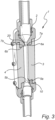
- the PEF chamber 1 comprises a PEF treatment tube 2 and opposite electrode units 3, 4 which are insertable into the PEF chamber 1.
- the electrode units 3, 4 are attachable and detachable by arranged screws.
- the opposite electrode units 3, 4 each has one flow receiving end 5a, 5b and one flow exit end 6a, 6b.
- the flow to be treated is pumped into the bottom and up through the PEF chamber 1 and PEF treatment tube 2.
- the flow receiving ends 5a, 5b are rounded or bent in an intended flow direction into the PEF treatment tube 2.
- the width of the electrode units (WE) is depicted in this embodiment.
- the PEF treatment tube 2 comprises exit flow portions 7a, 7b arranged subsequent to the flow exit ends 6a, 6b of the electrode units 3, 4 in the intended flow direction.
- These exit flow portions 7a, 7b are part of the isolating material arranged subsequent to the electrode units 3, 4, thus functioning as extensions of the opposite electrode units 3, 4 in the intended flow direction.
- these exit flow portions 7a, 7b are rounded or bent in an intended flow direction.
- the electrode units 3, 4 are arranged in the PEF treatment tube 2 to provide a first geometrical narrowing 10 at the flow receiving ends 5a, 5b.
- the exit flow portions 7a, 7b of the PEF treatment tube 2 are also arranged to provide a second geometrical narrowing 20 subsequent to the flow exit ends 6a, 6b. This implies that two geometrical narrowings are provided along the flow path from, in this case, lower inflow side to the upper outflow side.
- fig. 4 there is also shown an embodiment in line with the ones shown in figs. 1-3 .
- a gap distance GE between the opposite electrode units 3, 4 in the PEF chamber and the length LE of the electrodes are also depicted.
- a first tube distance 11 arranged before the opposite electrode units 3, 4 in the intended flow direction is also depicted.
- a second tube distance 21, which is the tube diameter subsequent to the electrodes is also shown in fig. 4 .
Landscapes
- Chemical & Material Sciences (AREA)
- Engineering & Computer Science (AREA)
- Life Sciences & Earth Sciences (AREA)
- Organic Chemistry (AREA)
- Food Science & Technology (AREA)
- Polymers & Plastics (AREA)
- Health & Medical Sciences (AREA)
- Chemical Kinetics & Catalysis (AREA)
- Hydrology & Water Resources (AREA)
- Nutrition Science (AREA)
- Water Supply & Treatment (AREA)
- Environmental & Geological Engineering (AREA)
- Electrochemistry (AREA)
- General Chemical & Material Sciences (AREA)
- Zoology (AREA)
- Wood Science & Technology (AREA)
- Toxicology (AREA)
- General Health & Medical Sciences (AREA)
- Food Preservation Except Freezing, Refrigeration, And Drying (AREA)
- Physical Or Chemical Processes And Apparatus (AREA)
Claims (7)
- PEF-Kammer (gepulste elektrische Feldkammer) (1) zur Behandlung einer Strömung mit elektrischen Feldimpulsen, wobei die PEF-Kammer ein PEF-Behandlungsrohr (2) und gegenüberliegende Elektrodeneinheiten (3, 4) umfasst, wobei die gegenüberliegenden Elektrodeneinheiten (3, 4) zwei flache parallele Elektrodeneinheiten (3, 4) sind, die zwei rechteckige Oberflächen freilegen und so angeordnet sind, dass ein pumpbares zu behandelndes Material zwischen den gegenüberliegenden Elektrodeneinheiten (3, 4) fließen kann, dadurch gekennzeichnet, dass jede der gegenüberliegenden Elektrodeneinheiten (3, 4) ein Strömungsaufnahmeende (5a, 5b) und ein Strömungsaustrittsende (6a, 6b) aufweist, wo die zu behandelnde Strömung zwischen den Strömungsaustrittsenden (6a, 6b) jeder gegenüberliegenden Elektrodeneinheit (3, 4) austritt, wobei das PEF-Behandlungsrohr (2) Austrittsströmungsabschnitte (7a, 7b) umfasst, die anschließend an die Strömungsaustrittsenden (6a, 6b) der Elektrodeneinheiten (3, 4) angeordnet sind, wobei die Austrittsströmungsabschnitte (7a, 7b) Teil des Isoliermaterials sind, das den Elektrodeneinheiten (3, 4) nachgeordnet ist, wobei die Austrittsströmungsabschnitte (7a, 7b) nicht Teil der Elektrodeneinheiten (3, 4) sind, sondern als Verlängerung der gegenüberliegenden Elektrodeneinheiten (3, 4) in der vorgesehenen Strömungsrichtung fungieren, wobei die gegenüberliegenden Elektrodeneinheiten (3, 4) längs verlaufen, wobei die Strömungsaufnahmeenden (5a, 5b) in einer vorgesehenen Strömungsrichtung in das PEF-Behandlungsrohr (2) gerundet sind, wobei die Austrittsströmungsabschnitte (7a, 7b) in einer beabsichtigten Strömungsrichtung gerundet sind, wobei die Elektrodeneinheiten (3, 4) in dem PEF-Behandlungsrohr (2) angeordnet sind, um eine erste geometrische Verengung (10) der Querschnittsfläche des PEF-Behandlungsrohrs (2) an den Strömungsaufnahmeenden (5a, 5b) der gegenüberliegenden Elektrodeneinheiten (3, 4) bereitzustellen, und wobei die Austrittsströmungsabschnitte (7a, 7b) des PEF-Behandlungsrohrs (2) angeordnet sind, um eine zweite geometrische Verengung (20) der Querschnittsfläche des PEF-Behandlungsrohrs (2) im Anschluss an die Strömungsaustrittsenden (6a, 6b) der gegenüberliegenden Elektrodeneinheiten (3, 4) bereitzustellen, wobei beide geometrischen Verengungen (10, 20) so angeordnet sind, dass die Querschnittsfläche des PEF-Behandlungsrohrs (2) in der geometrischen Verengung im Vergleich zu einem Punkt vor der vorgesehenen Strömungsrichtung verringert ist.
- PEF-Kammer (1) nach Anspruch 1, wobei jede Elektrodeneinheit (3, 4) in passende Nuten des PEF-Behandlungsrohrs (2) der PEF-Kammer (2) einsetzbar ist.
- PEF-Kammer (1) nach einem der vorhergehenden Ansprüche, wobei eine Beziehung eines Spaltabstands (GE) zwischen den gegenüberliegenden Elektrodeneinheiten (3, 4) in der PEF-Kammer (2) zu einer Länge (LE) jeder Elektrodeneinheit (3, 4) ein LE/GE-Verhältnis von mindestens 3, vorzugsweise mindestens 6, mehr bevorzugt mindestens 8, am meisten bevorzugt mindestens 10 aufweist, und/oder wobei eine Länge (LE) jeder Elektrodeneinheit (3, 4) mindestens 30 mm beträgt, vorzugsweise in einem Bereich von 30 - 600 mm, mehr bevorzugt in einem Bereich von 30 - 300 mm, mehr bevorzugt in einem Bereich von 30 - 200 mm, und wobei ein Spaltabstand (GE) zwischen den gegenüberliegenden Elektrodeneinheiten (3, 4) in der PEF-Kammer (2) mindestens 3 mm beträgt, vorzugsweise in einem Bereich von 3 - 45 mm und/oder wobei eine Breite (WE) jeder Elektrodeneinheit (3, 4) mindestens 3 mm beträgt, vorzugsweise im Bereich von 3 - 45 mm, und/oder wobei eine Beziehung eines Spaltabstands (GE) zwischen den gegenüberliegenden Elektrodeneinheiten (3, 4) in der PEF-Kammer (2), einer Länge (LE) jeder Elektrodeneinheit (3, 4) und einer Breite (WE) jeder Elektrodeneinheit (3, 4) in der Form von GE:WE:LE in einem Verhältnis von 3:3:20 mm bis 45:40:200 mm vorliegt.
- PEF-Kammer (1) nach einem der Ansprüche 1-3, wobei die erste geometrische Verengung (10) als ein Spaltabstand (GE) zwischen den gegenüberliegenden Elektrodeneinheiten (3, 4) angeordnet ist, wobei der (GE) im Bereich von 40 - 80%, vorzugsweise im Bereich von 45 - 64%, eines in der vorgesehenen Strömungsrichtung unmittelbar vor den gegenüberliegenden Elektrodeneinheiten (3, 4) angeordneten ersten Rohrabstandes (11) liegt, wobei der erste Rohrabstand (11) also der Abstand zwischen den Seiten des Isoliermaterialrohrs unmittelbar vor den gegenüberliegenden Elektrodeneinheiten (3, 4) ist.
- PEF-Kammer (1) nach einem der Ansprüche 1-4, wobei die zweite geometrische Verengung (20) mit einem zweiten Rohrabstand (21) angeordnet ist, der der Abstand zwischen den Seiten des Isoliermaterialrohrs unmittelbar anschließend an die gegenüberliegenden Elektrodeneinheiten (3, 4) ist, der im Bereich von 65 - 95%, vorzugsweise im Bereich von 70 - 80%, eines Spaltabstands (GE) zwischen den gegenüberliegenden Elektrodeneinheiten (3, 4) liegt.
- PEF-Kammer (1) nach einem der vorhergehenden Ansprüche, wobei das PEF-Behandlungsrohr (2) eine Turbulenzeinheit, vorzugsweise eine Helixeinheit, umfasst, die vor den Strömungsaufnahmeenden (5a, 5b) der Elektrodeneinheiten (3, 4) angeordnet ist.
- PEF-Kammer (1) nach einem der vorhergehenden Ansprüche, wobei ein Splitter am Ende eines Behandlungsvolumens des PEF-Behandlungsrohrs (2) angeordnet ist.
Applications Claiming Priority (2)
| Application Number | Priority Date | Filing Date | Title |
|---|---|---|---|
| SE1951028 | 2019-09-11 | ||
| PCT/SE2020/050853 WO2021049997A1 (en) | 2019-09-11 | 2020-09-11 | Pulsed electric field chamber |
Publications (4)
| Publication Number | Publication Date |
|---|---|
| EP4028155A1 EP4028155A1 (de) | 2022-07-20 |
| EP4028155A4 EP4028155A4 (de) | 2023-08-23 |
| EP4028155B1 true EP4028155B1 (de) | 2025-05-14 |
| EP4028155C0 EP4028155C0 (de) | 2025-05-14 |
Family
ID=72934539
Family Applications (1)
| Application Number | Title | Priority Date | Filing Date |
|---|---|---|---|
| EP20862456.9A Active EP4028155B1 (de) | 2019-09-11 | 2020-09-11 | Gepulste elektrische feldkammer |
Country Status (6)
| Country | Link |
|---|---|
| US (1) | US12245624B2 (de) |
| EP (1) | EP4028155B1 (de) |
| CN (2) | CN211770461U (de) |
| ES (1) | ES3038147T3 (de) |
| PL (1) | PL4028155T3 (de) |
| WO (1) | WO2021049997A1 (de) |
Families Citing this family (3)
| Publication number | Priority date | Publication date | Assignee | Title |
|---|---|---|---|---|
| CN211770461U (zh) * | 2019-09-11 | 2020-10-27 | Arc阿罗马珀尔公司 | 脉冲电场室 |
| DE102020209334A1 (de) * | 2020-07-23 | 2022-01-27 | DIL Deutsches Institut für Lebensmitteltechnik e.V. | Kompaktanlage für gepulste elektrische Felder in Behandlungszelle |
| KR102808325B1 (ko) * | 2022-06-15 | 2025-05-14 | 이동후 | 고전압 펄스 전기장 처리 장치 |
Citations (1)
| Publication number | Priority date | Publication date | Assignee | Title |
|---|---|---|---|---|
| CN101502304B (zh) * | 2009-03-12 | 2011-09-21 | 浙江大学 | 用于连续式液态食品灭菌的高压脉冲电场处理室 |
Family Cites Families (24)
| Publication number | Priority date | Publication date | Assignee | Title |
|---|---|---|---|---|
| DE69033273T2 (de) | 1989-06-12 | 1999-12-30 | Purepulse Technologies, Inc. | Gepulste hochspannungssysteme zur verlängerung der haltbarkeit von pumpfähigen nährmtteln |
| US5662031A (en) * | 1994-12-23 | 1997-09-02 | Washington State University Research Foundation, Inc. | Continuous flow electrical treatment of flowable food products |
| US5549041A (en) * | 1995-03-02 | 1996-08-27 | Washington State University Research Foundation | Batch mode food treatment using pulsed electric fields |
| US5690978A (en) * | 1996-09-30 | 1997-11-25 | Ohio State University | High voltage pulsed electric field treatment chambers for the preservation of liquid food products |
| NL1010529C2 (nl) * | 1998-11-11 | 2000-05-15 | Inst Voor Agrotech Onderzoek | Geïntegreerde modulaire opbouw van een pulsed electrical field systeem. |
| NL1014266C2 (nl) * | 2000-02-02 | 2001-08-03 | Stork Food & Dairy Systems Bv | Behandelingsinrichting en werkwijze voor het verduurzamen van verpompbare voedselproducten in een pulserend elektrisch veld. |
| US20040029240A1 (en) * | 2002-05-13 | 2004-02-12 | Acker Jesse L. | Dynamic electroporation apparatus and method |
| DE10349504A1 (de) * | 2003-10-23 | 2005-05-25 | Bayer Technology Services Gmbh | Verfahren zur Herstellung von Isocyanaten in der Gasphase |
| DE102004013762B4 (de) | 2004-03-20 | 2006-08-03 | Forschungszentrum Karlsruhe Gmbh | Verfahren zur besseren und schonenden Freisetzung wertgebender Inhaltsstoffe aus Weinbeeren und ein daraus gewonnener Most |
| PT1906772E (pt) | 2005-05-12 | 2015-10-20 | Estrella Maarud Holding As | Tratamento de batatas |
| JP4719184B2 (ja) * | 2007-06-01 | 2011-07-06 | 株式会社サイアン | 大気圧プラズマ発生装置およびそれを用いるワーク処理装置 |
| DE102008024065A1 (de) * | 2008-05-17 | 2009-11-19 | Forschungszentrum Karlsruhe Gmbh | Einrichtung und Verfahren zur druckgesteuerten und druckgeregelten, elektroporativen Behandlung biologisch pflanzlichem Prozessguts |
| JP2011072905A (ja) * | 2009-09-30 | 2011-04-14 | Sekisui Chem Co Ltd | 水処理装置 |
| NL2003853C2 (nl) * | 2009-11-23 | 2011-05-24 | Sonder Food Systems B V | Inrichting voor het pasteuriseren van een massa voedingswaar. |
| GB2487796A (en) | 2011-02-07 | 2012-08-08 | Cordon Ltd | Pulsed electric field treatment using boron doped diamond electrodes |
| JP5654946B2 (ja) * | 2011-05-11 | 2015-01-14 | 積水化学工業株式会社 | 水処理装置 |
| NL2009466C2 (nl) * | 2012-09-14 | 2014-03-18 | Zwanenberg Food Group B V | Inrichting voor het pasteuriseren van een massa voedingswaar. |
| JP6545171B2 (ja) * | 2013-12-10 | 2019-07-17 | ユニバーシティ オブ ハワイ | 生鮮材料の過冷却法 |
| BR112017022477A2 (pt) | 2015-04-21 | 2018-07-10 | Arc Aroma Pure Ab | câmara de campo elétrico pulsado |
| WO2017184066A1 (en) | 2015-04-21 | 2017-10-26 | Arc Aroma Pure Ab | Pef chamber |
| JP6587159B2 (ja) * | 2017-06-26 | 2019-10-09 | パナソニックIpマネジメント株式会社 | 液体処理装置 |
| DE102018202369A1 (de) * | 2018-02-15 | 2019-08-22 | Deutsches Institut Für Lebensmitteltechnik E.V. | Durchflusszelle zur Behandlung von Flüssigkeiten |
| CN109663556B (zh) * | 2019-01-27 | 2019-12-31 | 浙江大学 | 扰动增强型介质阻挡放电活化二氧化碳的反应装置及方法 |
| CN211770461U (zh) * | 2019-09-11 | 2020-10-27 | Arc阿罗马珀尔公司 | 脉冲电场室 |
-
2019
- 2019-10-23 CN CN201921783166.XU patent/CN211770461U/zh active Active
-
2020
- 2020-09-11 WO PCT/SE2020/050853 patent/WO2021049997A1/en not_active Ceased
- 2020-09-11 PL PL20862456.9T patent/PL4028155T3/pl unknown
- 2020-09-11 CN CN202080064362.0A patent/CN114728259B/zh active Active
- 2020-09-11 EP EP20862456.9A patent/EP4028155B1/de active Active
- 2020-09-11 ES ES20862456T patent/ES3038147T3/es active Active
- 2020-09-11 US US17/642,109 patent/US12245624B2/en active Active
Patent Citations (1)
| Publication number | Priority date | Publication date | Assignee | Title |
|---|---|---|---|---|
| CN101502304B (zh) * | 2009-03-12 | 2011-09-21 | 浙江大学 | 用于连续式液态食品灭菌的高压脉冲电场处理室 |
Also Published As
| Publication number | Publication date |
|---|---|
| WO2021049997A1 (en) | 2021-03-18 |
| CN211770461U (zh) | 2020-10-27 |
| PL4028155T3 (pl) | 2025-11-12 |
| US20220361533A1 (en) | 2022-11-17 |
| CN114728259B (zh) | 2024-03-12 |
| ES3038147T3 (en) | 2025-10-09 |
| CN114728259A (zh) | 2022-07-08 |
| EP4028155C0 (de) | 2025-05-14 |
| EP4028155A1 (de) | 2022-07-20 |
| EP4028155A4 (de) | 2023-08-23 |
| US12245624B2 (en) | 2025-03-11 |
Similar Documents
| Publication | Publication Date | Title |
|---|---|---|
| EP4028155B1 (de) | Gepulste elektrische feldkammer | |
| Huang et al. | Designs of pulsed electric fields treatment chambers for liquid foods pasteurization process: A review | |
| EP2490801B1 (de) | Verfahren zum behandeln eines fluiden mit mikrowellen | |
| TW409036B (en) | Uniform product flow in a high-electric-field treatment cell | |
| US6110423A (en) | High-strength-electric-field pumpable-food-product treatment in a serial-electrode treatment cell | |
| EP2334341B1 (de) | Resonanzkammer, insbesondere für ein gerät zur pasteurisierung von flüssigen produkten | |
| EP1912512B1 (de) | Vorrichtung zum anlegen von oszillierenden elektromagnetischen feldern, insbesondere zur behandlung von flüssigen, pastösen, halbstarren oder körnigen produkten, und verfahren zur verwendung solch einer vorrichtung und sie enthaltendes system | |
| CN102415599A (zh) | 基于耦合场结构优化的高压脉冲电场杀菌系统的共场处理室 | |
| AU2013316183B2 (en) | Device and method for providing a high voltage pulsed electric field to a fluid | |
| JP6030040B2 (ja) | 流動性食品材料の連続通電加熱装置 | |
| UA63001C2 (en) | Method and a device for treating fluids and fluid products | |
| EP1198997A2 (de) | Pulsierter Sterilisierungsapparat | |
| Ghnimi et al. | Tubular and fluid jet units | |
| Kempkes et al. | Scaleup of PEF systems for food and waste streams | |
| Gaudreau et al. | Scaleup of PEF systems for food and waste streams | |
| CN204180838U (zh) | 一种流道形状可调的高压脉冲电场杀菌系统同轴处理室 | |
| CN112357989B (zh) | 流体连续加热设备 | |
| Boyko et al. | Working chamber for processing foodstuffs by a complex action of strong pulsed electric fields | |
| JP2022051486A (ja) | 電界殺菌装置 | |
| Kempkes et al. | PEF systems for food and waste streams | |
| PL212906B1 (pl) | Urządzenie grzewcze cieczy w przepływie |
Legal Events
| Date | Code | Title | Description |
|---|---|---|---|
| STAA | Information on the status of an ep patent application or granted ep patent |
Free format text: STATUS: THE INTERNATIONAL PUBLICATION HAS BEEN MADE |
|
| PUAI | Public reference made under article 153(3) epc to a published international application that has entered the european phase |
Free format text: ORIGINAL CODE: 0009012 |
|
| STAA | Information on the status of an ep patent application or granted ep patent |
Free format text: STATUS: REQUEST FOR EXAMINATION WAS MADE |
|
| 17P | Request for examination filed |
Effective date: 20220407 |
|
| AK | Designated contracting states |
Kind code of ref document: A1 Designated state(s): AL AT BE BG CH CY CZ DE DK EE ES FI FR GB GR HR HU IE IS IT LI LT LU LV MC MK MT NL NO PL PT RO RS SE SI SK SM TR |
|
| DAV | Request for validation of the european patent (deleted) | ||
| DAX | Request for extension of the european patent (deleted) | ||
| REG | Reference to a national code |
Ref country code: DE Ref legal event code: R079 Free format text: PREVIOUS MAIN CLASS: B01J0019080000 Ipc: A61L0002030000 Ref country code: DE Ref legal event code: R079 Ref document number: 602020051392 Country of ref document: DE Free format text: PREVIOUS MAIN CLASS: B01J0019080000 Ipc: A61L0002030000 |
|
| A4 | Supplementary search report drawn up and despatched |
Effective date: 20230720 |
|
| RIC1 | Information provided on ipc code assigned before grant |
Ipc: C02F 1/46 20060101ALI20230714BHEP Ipc: B01J 19/08 20060101ALI20230714BHEP Ipc: A23L 3/32 20060101ALI20230714BHEP Ipc: A61L 2/03 20060101AFI20230714BHEP |
|
| STAA | Information on the status of an ep patent application or granted ep patent |
Free format text: STATUS: EXAMINATION IS IN PROGRESS |
|
| 17Q | First examination report despatched |
Effective date: 20240712 |
|
| REG | Reference to a national code |
Ref country code: DE Ref legal event code: R079 Free format text: PREVIOUS MAIN CLASS: A61L0002030000 Ipc: A23L0005300000 Ref country code: DE Ref legal event code: R079 Ref document number: 602020051392 Country of ref document: DE Free format text: PREVIOUS MAIN CLASS: A61L0002030000 Ipc: A23L0005300000 |
|
| GRAP | Despatch of communication of intention to grant a patent |
Free format text: ORIGINAL CODE: EPIDOSNIGR1 |
|
| STAA | Information on the status of an ep patent application or granted ep patent |
Free format text: STATUS: GRANT OF PATENT IS INTENDED |
|
| RIC1 | Information provided on ipc code assigned before grant |
Ipc: A23L 5/30 20160101AFI20250113BHEP |
|
| INTG | Intention to grant announced |
Effective date: 20250207 |
|
| GRAS | Grant fee paid |
Free format text: ORIGINAL CODE: EPIDOSNIGR3 |
|
| GRAA | (expected) grant |
Free format text: ORIGINAL CODE: 0009210 |
|
| STAA | Information on the status of an ep patent application or granted ep patent |
Free format text: STATUS: THE PATENT HAS BEEN GRANTED |
|
| AK | Designated contracting states |
Kind code of ref document: B1 Designated state(s): AL AT BE BG CH CY CZ DE DK EE ES FI FR GB GR HR HU IE IS IT LI LT LU LV MC MK MT NL NO PL PT RO RS SE SI SK SM TR |
|
| REG | Reference to a national code |
Ref country code: GB Ref legal event code: FG4D |
|
| REG | Reference to a national code |
Ref country code: CH Ref legal event code: EP |
|
| REG | Reference to a national code |
Ref country code: DE Ref legal event code: R096 Ref document number: 602020051392 Country of ref document: DE |
|
| REG | Reference to a national code |
Ref country code: IE Ref legal event code: FG4D |
|
| RAP4 | Party data changed (patent owner data changed or rights of a patent transferred) |
Owner name: OPTICEPT TECHNOLOGIES AB |
|
| U01 | Request for unitary effect filed |
Effective date: 20250613 |
|
| U07 | Unitary effect registered |
Designated state(s): AT BE BG DE DK EE FI FR IT LT LU LV MT NL PT RO SE SI Effective date: 20250620 |
|
| U20 | Renewal fee for the european patent with unitary effect paid |
Year of fee payment: 6 Effective date: 20250815 |
|
| REG | Reference to a national code |
Ref country code: ES Ref legal event code: FG2A Ref document number: 3038147 Country of ref document: ES Kind code of ref document: T3 Effective date: 20251009 |
|
| PG25 | Lapsed in a contracting state [announced via postgrant information from national office to epo] |
Ref country code: NO Free format text: LAPSE BECAUSE OF FAILURE TO SUBMIT A TRANSLATION OF THE DESCRIPTION OR TO PAY THE FEE WITHIN THE PRESCRIBED TIME-LIMIT Effective date: 20250814 |
|
| PGFP | Annual fee paid to national office [announced via postgrant information from national office to epo] |
Ref country code: GR Payment date: 20250827 Year of fee payment: 6 |
|
| PGFP | Annual fee paid to national office [announced via postgrant information from national office to epo] |
Ref country code: GB Payment date: 20250813 Year of fee payment: 6 |
|
| PG25 | Lapsed in a contracting state [announced via postgrant information from national office to epo] |
Ref country code: HR Free format text: LAPSE BECAUSE OF FAILURE TO SUBMIT A TRANSLATION OF THE DESCRIPTION OR TO PAY THE FEE WITHIN THE PRESCRIBED TIME-LIMIT Effective date: 20250514 |
|
| PG25 | Lapsed in a contracting state [announced via postgrant information from national office to epo] |
Ref country code: RS Free format text: LAPSE BECAUSE OF FAILURE TO SUBMIT A TRANSLATION OF THE DESCRIPTION OR TO PAY THE FEE WITHIN THE PRESCRIBED TIME-LIMIT Effective date: 20250814 |
|
| PG25 | Lapsed in a contracting state [announced via postgrant information from national office to epo] |
Ref country code: IS Free format text: LAPSE BECAUSE OF FAILURE TO SUBMIT A TRANSLATION OF THE DESCRIPTION OR TO PAY THE FEE WITHIN THE PRESCRIBED TIME-LIMIT Effective date: 20250914 |
|
| REG | Reference to a national code |
Ref country code: GR Ref legal event code: EP Ref document number: 20250401581 Country of ref document: GR Effective date: 20251009 |
|
| PG25 | Lapsed in a contracting state [announced via postgrant information from national office to epo] |
Ref country code: SM Free format text: LAPSE BECAUSE OF FAILURE TO SUBMIT A TRANSLATION OF THE DESCRIPTION OR TO PAY THE FEE WITHIN THE PRESCRIBED TIME-LIMIT Effective date: 20250514 |
|
| PG25 | Lapsed in a contracting state [announced via postgrant information from national office to epo] |
Ref country code: CZ Free format text: LAPSE BECAUSE OF FAILURE TO SUBMIT A TRANSLATION OF THE DESCRIPTION OR TO PAY THE FEE WITHIN THE PRESCRIBED TIME-LIMIT Effective date: 20250514 |
|
| PGFP | Annual fee paid to national office [announced via postgrant information from national office to epo] |
Ref country code: PL Payment date: 20250801 Year of fee payment: 6 |
|
| PG25 | Lapsed in a contracting state [announced via postgrant information from national office to epo] |
Ref country code: SK Free format text: LAPSE BECAUSE OF FAILURE TO SUBMIT A TRANSLATION OF THE DESCRIPTION OR TO PAY THE FEE WITHIN THE PRESCRIBED TIME-LIMIT Effective date: 20250514 |
|
| PGFP | Annual fee paid to national office [announced via postgrant information from national office to epo] |
Ref country code: ES Payment date: 20251001 Year of fee payment: 6 |