EP4028152B1 - Mischvorrichtung für kosmetika, dispenser und verwendung der mischvorrichtung - Google Patents
Mischvorrichtung für kosmetika, dispenser und verwendung der mischvorrichtung Download PDFInfo
- Publication number
- EP4028152B1 EP4028152B1 EP20761765.5A EP20761765A EP4028152B1 EP 4028152 B1 EP4028152 B1 EP 4028152B1 EP 20761765 A EP20761765 A EP 20761765A EP 4028152 B1 EP4028152 B1 EP 4028152B1
- Authority
- EP
- European Patent Office
- Prior art keywords
- mixing
- mixing device
- passages
- preparations
- dispenser
- Prior art date
- Legal status (The legal status is an assumption and is not a legal conclusion. Google has not performed a legal analysis and makes no representation as to the accuracy of the status listed.)
- Active
Links
Images


Classifications
-
- A—HUMAN NECESSITIES
- A45—HAND OR TRAVELLING ARTICLES
- A45D—HAIRDRESSING OR SHAVING EQUIPMENT; EQUIPMENT FOR COSMETICS OR COSMETIC TREATMENTS, e.g. FOR MANICURING OR PEDICURING
- A45D40/00—Casings or accessories specially adapted for storing or handling solid or pasty toiletry or cosmetic substances, e.g. shaving soaps or lipsticks
- A45D40/26—Appliances specially adapted for applying pasty paint, e.g. using roller, using a ball
-
- B—PERFORMING OPERATIONS; TRANSPORTING
- B01—PHYSICAL OR CHEMICAL PROCESSES OR APPARATUS IN GENERAL
- B01F—MIXING, e.g. DISSOLVING, EMULSIFYING OR DISPERSING
- B01F25/00—Flow mixers; Mixers for falling materials, e.g. solid particles
- B01F25/40—Static mixers
- B01F25/45—Mixers in which the materials to be mixed are pressed together through orifices or interstitial spaces, e.g. between beads
- B01F25/452—Mixers in which the materials to be mixed are pressed together through orifices or interstitial spaces, e.g. between beads characterised by elements provided with orifices or interstitial spaces
- B01F25/4521—Mixers in which the materials to be mixed are pressed together through orifices or interstitial spaces, e.g. between beads characterised by elements provided with orifices or interstitial spaces the components being pressed through orifices in elements, e.g. flat plates or cylinders, which obstruct the whole diameter of the tube
-
- B—PERFORMING OPERATIONS; TRANSPORTING
- B01—PHYSICAL OR CHEMICAL PROCESSES OR APPARATUS IN GENERAL
- B01F—MIXING, e.g. DISSOLVING, EMULSIFYING OR DISPERSING
- B01F33/00—Other mixers; Mixing plants; Combinations of mixers
- B01F33/50—Movable or transportable mixing devices or plants
- B01F33/501—Movable mixing devices, i.e. readily shifted or displaced from one place to another, e.g. portable during use
- B01F33/5011—Movable mixing devices, i.e. readily shifted or displaced from one place to another, e.g. portable during use portable during use, e.g. hand-held
- B01F33/50111—Small portable bottles, flasks, vials, e.g. with means for mixing ingredients or for homogenizing their content, e.g. by hand shaking
-
- B—PERFORMING OPERATIONS; TRANSPORTING
- B01—PHYSICAL OR CHEMICAL PROCESSES OR APPARATUS IN GENERAL
- B01F—MIXING, e.g. DISSOLVING, EMULSIFYING OR DISPERSING
- B01F35/00—Accessories for mixers; Auxiliary operations or auxiliary devices; Parts or details of general application
- B01F35/75—Discharge mechanisms
- B01F35/754—Discharge mechanisms characterised by the means for discharging the components from the mixer
- B01F35/7547—Discharge mechanisms characterised by the means for discharging the components from the mixer using valves, gates, orifices or openings
-
- B—PERFORMING OPERATIONS; TRANSPORTING
- B05—SPRAYING OR ATOMISING IN GENERAL; APPLYING FLUENT MATERIALS TO SURFACES, IN GENERAL
- B05B—SPRAYING APPARATUS; ATOMISING APPARATUS; NOZZLES
- B05B11/00—Single-unit hand-held apparatus in which flow of contents is produced by the muscular force of the operator at the moment of use
- B05B11/01—Single-unit hand-held apparatus in which flow of contents is produced by the muscular force of the operator at the moment of use characterised by the means producing the flow
- B05B11/10—Pump arrangements for transferring the contents from the container to a pump chamber by a sucking effect and forcing the contents out through the dispensing nozzle
- B05B11/1081—Arrangements for pumping several liquids or other fluent materials from several containers, e.g. for mixing them at the moment of pumping
-
- A—HUMAN NECESSITIES
- A45—HAND OR TRAVELLING ARTICLES
- A45D—HAIRDRESSING OR SHAVING EQUIPMENT; EQUIPMENT FOR COSMETICS OR COSMETIC TREATMENTS, e.g. FOR MANICURING OR PEDICURING
- A45D2200/00—Details not otherwise provided for in A45D
- A45D2200/05—Details of containers
- A45D2200/058—Means for mixing different substances prior to application
-
- B—PERFORMING OPERATIONS; TRANSPORTING
- B01—PHYSICAL OR CHEMICAL PROCESSES OR APPARATUS IN GENERAL
- B01F—MIXING, e.g. DISSOLVING, EMULSIFYING OR DISPERSING
- B01F2101/00—Mixing characterised by the nature of the mixed materials or by the application field
- B01F2101/21—Mixing of ingredients for cosmetic or perfume compositions
Definitions
- the invention is a mixing device in particular for cosmetic dispensers.
- Dispenser or dosing dispenser is a term for various manual, semi-automatic or automatic dispensing devices.
- compressed air-operated pump bottles or atomizers
- air-free pump bottles or dispensers in which the product is pushed out of the outlet nozzle in its liquid form by the retracted piston.
- a dispenser has the advantage over an atomizer that no compressed air is required.
- a major disadvantage is the sometimes complicated structure compared to other packaging materials such as tubes or jars.
- the preparation may contain particulate components, spheres, bubbles or other shapes. Some components are partially unstable in the preparation environment, so they are introduced in encapsulated form. These capsules must be crushed or ground before application in order to be able to be applied or so that the encapsulated active ingredient can be released and take effect.
- the invention is a mixing device according to claim 1 for liquid or flowable materials, in particular for cosmetic preparations such as creams, ointments, gels, emulsions.
- the mixing device comprises at least two mixing plates spaced apart from one another, each having a plurality of passages that taper in the direction of flow.
- the mixing device enables the mixing of one or more preparations in a dispenser with a dispensing opening.
- the mixing device comprises at least two mixing plates, each of which has one or more passages.
- the diameters of the passages taper in the direction of the dispensing opening, i.e. in the direction of flow when dispensing the preparation.
- the two or more mixing plates are arranged one after the other in the direction of the dispensing opening so that the preparation can flow through one mixing plate after the other.
- mixing plates are arranged one after the other in the direction of the dispenser's dispensing opening. All diameters of the passages at the flow outlet of a mixing plate are ideally the same. However, according to the invention, the diameters of the passages at the flow outlet of the mixing plates arranged one after the other towards the dispensing opening are always smaller in diameter. This means that the mixing plate at the outlet opening has the passages with the smallest diameters.
- the mixing plate through which the preparations to be mixed flow first has the passages with the largest diameters at the flow outlet.
- the mixing plate through which the mixture flows next has passages whose diameters are smaller at the flow outlet.
- dispensers comprising one or more mixing devices according to the invention, advantageously dispensers for cosmetics.
- the dispensers then comprise one or more preparations to be mixed, with at least one preparation comprising two or more phases.
- the preparations to be mixed are cosmetic preparations that are flowable, pumpable and/or pasty at least at room temperature. It is of course advantageous that they are flowable, pumpable and/or pasty in the temperature range from -50° to 50°C.
- the distance between the mixing plates is advantageously 0.1 to 1 mm, ideally in the range of 0.3 to 0.6 mm.
- the mixing plates advantageously have a thickness of 0.05 to 1.5 mm, ideally in the range of 0.5 mm.
- the passages/passages have a diameter at the flow outlet of 0.1 to 10 mm, ideally in the range of 0.2 to 1 mm, in particular 0.3 to 0.6 mm. In the direction of flow, the passages taper to these smaller diameters at the outlet.
- the passages preferably have the shape of a cone segment.
- the height of the cone segment, the passage corresponds to the thickness of the mixing plate and the specified diameter of the cone segment corresponds to the diameter of the passage at the flow outlet.
- the diameter can be selected relatively arbitrarily; according to the invention, the only decisive factor is that the diameter tapers over the height of the passage/thickness of the mixing plate.
- the taper from the flow inlet to the flow outlet of the passage can be linear, as with the cone segment, curved or in steps. According to the invention, a taper takes place when the diameter of the passage at the flow inlet is larger than the diameter of the passage at the flow outlet.
- the mixing plates are preferably made of plastic.
- the mixing device according to the invention is used in dispensers, pumps, mixing systems, etc., particularly for cosmetics.
- a dispenser comprises two storage containers containing two different preparations which are to be dispensed together.
- the two preparations are pumped in parallel via riser pipes to the dispenser's dispensing opening.
- the mixing device according to the invention can now simply be inserted in front of the dispensing opening of a dispenser.
- the mixing device according to the invention is particularly advantageous when mixing two or more preparations if at least one of these preparations comprises particulate components which are to be divided, split or crushed before application to the skin.
- a preparation comprising particulate constituents, in particular spherical particles advantageously comprises an outer flowable gel-like phase, which optionally contains auxiliary and/or additives customary in cosmetics, and an inner particulate phase which comprises essentially spherical particles whose average diameter is selected from the range of 0.1 to 10 mm, preferably 0.2 to 7.5 mm.
- the particles are advantageously thixotropic to ensure complete dissolution during the mixing process.
- the particles should have a flow limit to avoid dissolution in the suspending medium.
- the preparations to be mixed are therefore flowable to pasty and are advantageously structured in two or more phases.
- At least one of the preparations to be mixed is two- or multi-phase.
- Multiphase means that at least two phases exist within a preparation.
- the phases differ in one or more properties, such as viscosity, density, Lipophilicity and/or state of aggregation.
- This includes, for example, common flowable emulsion-based preparations that contain particulate components.
- the emulsion forms one phase, the particles the other phase.
- the particles in the preparation which contain an active ingredient or dye, for example, can be stored in a transparent dispenser in a visually attractive manner.
- the preparation flows through the mixing device according to the invention and at the end a preparation is applied in which the active ingredient/dye achieves the desired effect on the skin or the desired color effect.
- a cosmetic dispenser for example, has two chambers, each of which contains a cosmetic preparation.
- one chamber contains biopolymer balls distributed in a gel liquid and the second chamber contains an emulsion.
- Both preparations can be pumped up to the outlet via a hose. Pumping is done simply by mechanically pressing down the pump body, which is attached to the cosmetic dispenser. The pump body is then pulled back up again by a stainless steel spring, for example, which creates a vacuum that sucks the contents, the two preparations, into the pump body via the hose.
- Balls made of plastic or glass serve as valves, sealing the pump body towards the hose and towards the outlet opening.
- the mixing device according to the invention is located in the flow path in front of the outlet, the dispensing opening of the dispenser, so that no preparation can be pushed past the edge of the mixing plates.
- the mixing attachment advantageously covers the respective preparation inlets and encloses the mixing plates at the edge so that the preparations can only flow through the mixing plates to the dispensing point.
- both pumps of the dispenser are activated simultaneously.
- the two preparations are pressed into the mixing device by the pumping stroke.
- the preparations flow from below through the passages of the mixing plates. Since the passages taper in the direction of flow towards the flow outlet, the Biopolymer balls and the broken ball components are mixed with the second preparation, the emulsion. A gel cream is created in the mixing device which is then dispensed.
- two or more mixing plates are connected in series according to the invention, an even better mixing result is achieved. It is also preferred if two or more mixing plates each have through holes that become smaller in diameter towards the outlet.
- each mixing plate comprises several passes and advantageously almost the same number of passes.
- the passages of the mixing plate through which the preparations flow first preferably have a larger diameter at the flow outlet than the passages of the mixing plate through which the preparations flow subsequently.
- mixing plates are arranged one behind the other. Then, on the one hand, the end diameters of the passages are reduced from mixing plate to mixing plate and, since according to the invention the passages taper in the direction of flow, the mixing result is further optimized from plate to plate.
- the mixing result is optimized for the mixing result through the static mixing system plus the force that has to be applied in the application, the pressure on the pump button/mechanism.
- the pump output is advantageously 0.1 to 0.5 g, especially in the range of 0.15 to 0.25 g, per pump stroke.
- Figure 1 outlines and illustrates a mixing device according to the invention with 3 mixing plates (1) in which several passages (2) are provided.
- the mixing device comprises a mixing attachment (3) with two openings (4) at the preparation inlet through which the two preparations (5, 6) are pressed into the mixing device.
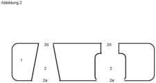
- Figure 2 shows a mixing plate (1) with two geometrically different passages (2).
- the preferred shape of a cone segment is shown on the left. Another possible shape is shown on the right.
- Figure 3 shows 4 mixing plates (1) one above the other in a dispenser.
- the preparations (5, 6) are pressed into the mixing plate (1) from below. They flow through the passages (2) of the first mixing plate.
- the passages (2) of the first mixing plate have a diameter of 0.5 mm at the flow outlet (2d).
- the second mixing plate is spaced 0.55 mm from the first mixing plate (7).
- the passages (2) of the second mixing plate have a diameter at the flow outlet (2d) of 0.45 mm
- the passages (2) of the third mixing plate have a diameter at the flow outlet (2d) of 0.4 mm
- the passages (2) of the fourth mixing plate have a diameter at the flow outlet (2d) of 0.35 mm
- Figure 4 shows a dispenser (9) with 4 mixing plates (1).
- the preparations (5, 6) are transported via the riser pipe through the mixing plates (1) to the outlet (8) of the dispenser.
- mixing plate 1 passage/opening of the mixing plate 2 Diameter of the passage of the mixing plate at the flow inlet 2a Diameter of the passage of the mixing plate at the flow outlet 2d mixing attachment 3 opening/passage of the mixing attachment 4 preparation to be mixed 5, 6 distance between the mixing plates 7 dispenser output 8 dispenser 9
Landscapes
- Chemical & Material Sciences (AREA)
- Chemical Kinetics & Catalysis (AREA)
- Dispersion Chemistry (AREA)
- Containers And Packaging Bodies Having A Special Means To Remove Contents (AREA)
- Accessories For Mixers (AREA)
- Cosmetics (AREA)
Description
- Die Erfindung ist eine Mischvorrichtung insbesondere für Kosmetikdispenser.
- Dispenser oder Dosierspender ist eine Bezeichnung für verschiedene manuelle, halbautomatische oder automatische Ausgabevorrichtungen.
- In der Kosmetik finden Pumpvorrichtungen, Dispenser, insbesondere aus Kunststoff breite Anwendung.
- Man unterscheidet je nach der Austrittsweise des Produkts druckluftbetriebene Pumpflaschen (oder Zerstäuber), bei denen das Produkt durch den in der Flasche herrschenden Überdruck einer Druckluft in ein Aerosol feingeteilt und unter Druck ausgestrahlt wird, und luftfreie Pumpflaschen oder Dispenser, bei denen das Produkt durch den eingefahrenen Kolben aus der Austrittsdüse in seiner flüssigen Form bleibend herausgedrückt wird. Ein Dispenser hat gegenüber einem Zerstäuber die Vorteile, dass keine Druckluft benötigt wird.
- Weitere Spendersysteme sind im Stand der Technik bekannt. Insbesondere sog. Airlesssysteme mit Schleppkolben sind weitverbreitet.
- Spendersysteme mit Schleppkolben erfreuen sich insbesondere in der kosmetischen Industrie großer Beliebtheit. Sie weisen insbesondere folgende Vorteile auf:
- entnommenes Füllvolumen wird nicht durch Luft ersetzt, dadurch auch für oxidationsempfindliche Zubereitungen einsetzbar,
- äußere Gestalt bleibt während des gesamten Benutzungszeitraumes erhalten,
- Behältnis steht nicht unter Druck und
- einfache Dosierung möglich.
- Ein gewichtiger Nachteil ist der teilweise komplizierte Aufbau gegenüber anderen Verpackungsmitteln wie Tuben oder Tiegeln.
- Diese Pumpen sind sehr weit verbreitet und werden für alle Arten von flüssigen und gelartigen, nicht zu festen Seifen, Cremes, Lotion usw. eingesetzt. Dabei wird die Pumpe einfach auf eine PET oder PE Flasche geschraubt und das Füllgut über einen Schlauch nach oben gepumpt. Gepumpt wird einfach durch mechanisches nach unten drücken des Pumpkörpers. Der Pumpkörper wird dann durch eine Edelstahlfeder wieder nach oben gezogen, wodurch ein Vakuum entsteht, welches das Füllgut über den Schlauch in den Pumpenkörper saugt. Als Ventile dienen Kugeln aus Kunststoff oder Glas, welche den Pumpenkörper in Richtung
- Schlauch und in Richtung Austrittsöffnung abdichten. Gleichzeitig werden beim Pumpvorgang Kanäle geöffnet, welche das Einströmen von Luft in den Behälter erlauben, die Flasche würde sich ansonsten zusammenziehen und die Förderleistung der Pumpe wäre negativ beeinträchtigt. Probleme ergeben sich sobald das Füllgut oder eine der zu mischenden Zubereitungen unterschiedliche Phasen aufweisen. Dadurch besteht die Möglichkeit der visuellen Differenzierung sowie die Möglichkeit der Trennung von inkompatiblen Inhalts-/Wirkstoffen. Jedoch ergeben sich daraus auch Probleme der dann doch gewünschten homogenen Ausbringung.
- Beispielsweise sind in der Zubereitung partikuläre Bestandteile, Kugeln, Blasen oder andere Formen enthalten. Manche Bestandteile sind teilweise instabil in der Zubereitungsumgebung, so dass sie verkapselt eingebracht werden. Diese Kapseln müssen vor der Applikation zerkleinert, zerrieben werden um ausgebracht werden zu können bzw. damit der verkapselte Wirkstoff freigesetzt und wirken kann.
- Wünschenswert ist es ein Mischsystem zur Verfügung zu stellen, mit dem Zubereitungen vermischt werden können, die unterschiedliche Phasen aufweisen.
- Dokument
DE 101 26 267 A1 offenbart eine Mischvorrichtung nach dem Oberbegriff des Anspruchs 1. - Die Erfindung ist eine Mischvorrichtung nach Anspruch 1 für flüssige oder fließfähige Materialien, insbesondere für kosmetische Zubereitungen, wie Creme, Salben, Gele, Emulsionen. Die Mischvorrichtung umfasst mindestens zwei voneinander beabstandete Mischplatten, die jeweils mehrere Durchgänge aufweisen, die sich in Fließrichtung verjüngen.
- Die erfindungsgemäße Mischvorrichtung ermöglicht das Mischen von ein oder mehreren Zubereitungen in einem Dispenser mit einer Ausgabeöffnung.
- Die Mischvorrichtung umfasst mindestens zwei Mischplatten, die jeweils ein oder mehrere Durchgänge aufweisen. Die Durchmesser der Durchgänge verjüngen sich in Richtung der Ausgabeöffnung, d.h. in Fließrichtung beim Ausgeben der Zubereitung. Die zwei oder mehreren Mischplatten sind nacheinander in Richtung der Ausgabeöffnung angeordnet, damit die Zubereitung eine Mischplatte nach der anderen durchströmen kann.
- Vorteilhaft sind vier Mischplatten nacheinander in Richtung der Ausgabeöffnung des Dispensers angeordnet. Alle Durchmesser der Durchgänge am Fließausgang einer Mischplatte sind idealerweise gleich. Jedoch werden erfindungsgemäß die Durchmesser der Durchgänge am Fließausgang der nacheinander angeordneten Mischplatten zur Ausgabeöffnung hin immer kleiner im Durchmesser. D.h. die Mischplatte an der Ausgabeöffnung hat die Durchgänge mit den kleinsten Durchmessern.
- So hat die zuerst von der zu mischenden Zubereitungen durchströmten Mischplatte die Durchgänge mit den größten Durchmessern am Fließausgang. Die danach durchströmte Mischplatte hat dann Durchgänge deren Durchmesser am Fließausgang geringer sind.
- Erfindungsgemäß sind ebenso Dispenser umfassend ein oder mehrere erfindungsgemäße Mischvorrichtungen, vorteilhaft Dispenser für Kosmetika.
- Die Dispenser umfassen dann ein oder mehrere zu vermischende Zubereitungen, wobei zumindest eine Zubereitung zwei oder mehrere Phasen umfasst.
- Insbesondere handelt es sich bei den zu vermischenden Zubereitungen um kosmetische Zubereitung, die zumindest bei Raumtemperatur fließfähig, pumpbar und/oder pastös sind. Vorteilhaft ist natürlich, dass sie in Temperaturbereich von - 50° bis 50°C fließfähig, pumpbar und/oder pastös sind.
- Der Abstand zwischen den Mischplatten beträgt vorteilhaft 0,1 bis 1 mm, idealerweise im Bereich von 0,3 bis 0,6 mm.
- Die Mischplatten haben vorteilhaft eine Dicke von 0,05 bis 1,5 mm, idealerweise im Bereich von 0,5 mm. Die Durchgänge/Durchlässe weisen einen Durchmesser am Fließausgang von 0,1 bis 10 mm, idealerweise im Bereich von 0,2 bis 1 mm, insbesondere 0,3 bis 0,6 mm, auf. In Fließrichtung verjüngen sich die Durchgänge auf entsprechend diese kleineren Durchmesser am Ausgang.
- Die Durchgänge haben aufgrund ihrer Verjüngung bevorzugt die Form eines Kegelsegmentes. Die Höhe des Kegelsegmentes, des Durchgangs, entspricht der Dicke der Mischplatte und der angegebene Durchmesser des Kegelsegmentes entspricht dem Durchmesser des Durchganges am Fließausgang.
- Am Fließeingang des Durchganges kann der Durchmesser relativ beliebig gewählt werden, erfindungsgemäß entscheidend ist nur, dass sich über die Höhe des Durchganges/Dicke der Mischplatte der Durchmesser verjüngt.
- Die Verjüngung vom Fließeingang zum Fließausgang des Durchgangs kann linear erfolgen, wie beim Kegelsegment, gewölbt oder in Stufen. Eine Verjüngung findet erfindungsgemäß statt, wenn der Durchmesser des Durchgangs am Fließeingang größer ist als der Durchmesser des Durchgangs am Fließausgang.
- Die Mischplatten bestehen bevorzugt aus Kunststoff.
- Vorteilhaft werden 4 Mischplatten hintereinander beabstandet.
- Die erfindungsgemäße Mischvorrichtung kommt in Dispensern, Pumpen, Mischsystemen o.a. insbesondere für Kosmetika zum Einsatz.
- Beispielsweise umfasst ein Dispenser zwei Vorratsbehälter in denen zwei unterschiedliche Zubereitungen enthalten sind, die aber vermischt ausgegeben werden sollen.
- Über eine Pumpvorrichtung werden die beiden Zubereitungen parallel über Steigrohre zur Ausgabeöffnung des Dispensers gepumpt. Die erfindungsgemäße Mischvorrichtung kann nun einfach vor die Ausgabeöffnung eines Dispensers eingesetzt werden.
- Vorteilhaft zeigt sich die erfindungsgemäße Mischvorrichtung insbesondere bei der Mischung zwei oder mehrerer Zubereitungen, wenn zumindest eine dieser Zubereitungen partikulare Bestandteile umfassen, die vor der Applikation auf der Haut zerteilt, aufgespalten oder zequetscht werden sollen.
- Eine Zubereitung umfassend partikuläre Bestandteile, insbesondere kugelförmige Partikel, umfasst vorteilhaft eine äußere fließfähige gelartige Phase, welche gegebenenfalls in der Kosmetik übliche Hilfs- und oder Zusatzstoffe enthält, und die eine innere partikuläre Phase, welche im wesentlichen kugelförmige Partikel umfasst, deren mittlerer Durchmesser gewählt wird aus dem Bereich von 0,1 bis 10 mm, bevorzugt 0,2 bis 7,5 mm.
- Die Partikel sind vorteilhaft thixotrop um eine vollständige Auflösung beim Mischvorgang zu gewährleisten. Zudem sollten die Partikel eine Fliessgrenze aufweisen um ein Auflösen im suspendierenden Medium zu vermeiden.
- D.h. vorteilhaft, dass der Osmotische Druck zwischen innerem und äusseren Medium ähnlich sein muss, um ein unkontrolliertes Anquellen / Auflösung der Partikel über die Zeit zu vermeiden.
- Die zu mischenden Zubereitungen sind daher fließfähig bis pastös und sind vorteilhaft zwei bis mehrphasig aufgebaut.
- Sofern zwei oder mehrere verschiedene Zubereitungen gemischt werden sollen, ist zumindest ein der zu mischenden Zubereitungen zwei- oder mehrphasig.
- Mehrphasig bedeutet, dass innerhalb einer Zubereitung mindestens zwei Phasen existieren. Die Phasen unterscheiden sich durch ein oder mehrere Eigenschaften, wie Viskosität, Dichte, Lipophilie und/oder Aggregatzustand. Damit sind beispielsweise übliche fließfähige emulsionsbasierte Zubereitungen umfasst in denen partikuläre Bestandteile enthalten sind.
- Die Emulsion bildet die ein Phase, die Partikel die andere Phase. Die in der Zubereitung befindlichen Partikel, die z.B. einen Wirkstoff oder Farbstoff enthalten, können so optisch attraktiv in einem transparenten Dispenser gelagert werden. Beim Ausbringen strömt die Zubereitung durch die erfindungsgemäße Mischvorrichtung und am Ende wird eine Zubereitung ausgebracht bei der der Wirkstoff/Farbstoff die gewünschte Wirkung auf der Haut bzw. den gewünschten Farbeffekt erreicht.
- Ebenso ist es bevorzugt wenn zwei verschiedenen Zubereitungen gemischt werden, wie nachfolgend in den Beispielen exemplarisch erläutert wird.
- Eine erfindungsgemäße Ausführungsform wird nachfolgend beschrieben.
- Ein Kosmetikspender umfasst beispielsweise zwei Kammern in denen sich jeweils eine kosmetische Zubereitungen befindet. Beispielsweise umfasst die eine Kammer Biopolymerkugeln in einer Gelflüssigkeit verteilt und in der zweiten Kammer eine Emulsion. Beide Zubereitungen können über einen Schlauch nach oben zum Auslaß gepumpt werden. Gepumpt wird einfach durch mechanisches nach unten drücken des Pumpkörpers, der am Kosmetikspender angebracht ist. Der Pumpkörper wird dann beispielsweise durch eine Edelstahlfeder wieder nach oben gezogen, wodurch ein Vakuum entsteht, welches das Füllgut, die beiden Zubereitungen, über den Schlauch in den Pumpenkörper saugt. Als Ventile dienen Kugeln aus Kunststoff oder Glas, welche den Pumpenkörper in Richtung Schlauch und in Richtung Austrittsöffnung abdichten.
- Vor dem Auslaß, der Ausgabeöffnung des Dispensers befindet sich die erfindungsgemäße Mischvorrichtung im Strömungsgang, so dass keine Zubereitung am Rand der Mischplatten vorbei gedrückt werden kann.
- Vorteilhaft werden die Mischplatten am Rand durch einen Mischaufsatz begrenzt.
- Der Mischaufsatz umfasst vorteilhaft die jeweiligen Zubereitungseingänge und umschließt die Mischplatten am Rand, so dass die Zubereitungen nur durch die Mischplatten zur Ausgabe strömen können.
- Beim Pumpen werden beide Pumpen des Spenders gleichzeitig betätigt.
- Die beiden Zubereitungen werden durch den Pumpstoss in die Mischvorrichtung gedrückt. Die Zubereitungen strömen von unten durch die Durchgänge der Mischplatten. Da sich die Durchgänge in Strömungsrichtung hin zum Fließauslaß verjüngen brechen die Biopolymerkugeln und es erfolgt eine Vermischung der gebrochenen Kugelbestandteile mit der zweiten Zubereitung, der Emulsion. Es entsteht eine Gelcreme in der Mischvorrichtung die dann ausgegeben wird.
- Wird nun erfindungsgemäß zwei oder mehrere Mischplatten hintereinander geschaltet wird ein noch besseres Mischergebnis erzielt. Ebenso ist es bevorzugt wenn zwei oder mehrere Mischplatten jeweils zum Auslaß hin immer kleiner im Durchmesser werdende Durchgangöffnungen aufweisen.
- Somit werden auch noch nicht zerkleinerte Partikel bis zum End-Auslaß zermahlen und das Mischergebnis ist wiederum verbessert.
- Vorteilhaft umfasst jede Mischplatte mehrere Durchgänge und vorteilhaft nahezu gleich viele Durchgänge.
- Die Durchgänge der Mischplatte, die zuerst von den Zubereitungen durchströmt wird, haben bevorzugt einen größeren Durchmesser am Fließausgang als die Durchgänge der danach durchströmten Mischplatte.
- Vorteilhafterweise werden mehrere, idealerweise 4, Mischplatten hintereinander angeordnet. Dann verkleinern sich einerseits die Enddurchmesser der Durchgänge von Mischplatte zu Mischplatte und da erfindungsgemäß sich die Durchgänge in Strömungsrichtung verjüngen, wird von Platte zu Platte damit das Mischergebnis weiter optimiert.
- Das Mischresultat ist optimiert auf das Mischergebnis durch das statische Mischsystem plus die Kraft die aufzuwenden ist in der Anwendung, dem Druck auf den Pumpbutton/Mechanismus. Die Pumpausbringmenge beträgt vorteilhaft 0,1 bis 0,5 g, insbesondere im Bereich von 0,15 bis 0,25 g, pro Pumpstoß.
-
Abbildung 1 skizziert und veranschaulicht eine erfindungsgemäße Mischvorrichtung mit 3 Mischplatten (1) in denen mehrere Durchgänge (2) vorgesehen sind. Die Mischvorrichtung umfasst am Zubereitungseingang einen Mischaufsatz (3) mit zwei Öffnungen (4) durch die die beiden Zubereitungen (5, 6) in die Mischvorrichtung gedrückt werden. -
Abbildung 2 zeigt eine Mischplatte (1) mit zwei geometrisch verschiedenen Durchgängen (2). Die bevorzugte Form eines Kegelsegmentes ist links abgebildet. Eine andere mögliche Form ist rechts abgebildet. Bei allen möglichen Formen ist entscheidend, dass der Durchmesser der Durchgänge (2) am Fließausgang (2d) kleiner ist als der Durchmesser der Durchgänge am Fießeingang (2a). -
Abbildung 3 zeigt 4 Mischplatten (1) übereinander in einem Dispenser. Von unten werden die Zubereitungen (5, 6) in die Mischplatte (1) gedrückt. Sie fließen durch die Durchgänge (2) der ersten Mischplatte. Die Durchgänge (2) der ersten Mischplatte haben einen Durchmesser am Fließausgang (2d) von 0,5 mm. - Die zweite Mischplatte ist von der ersten Mischplatte um 0,55 mm beabstandet (7).
- Die Durchgänge (2) der zweiten Mischplatte haben einen Durchmesser am Fließausgang (2d) von 0,45 mm, die Durchgänge (2) der dritten Mischplatte haben einen Durchmesser am Fließausgang (2d) von 0,4 mm und die Durchgänge (2) der vierten Mischplatte haben einen Durchmesser am Fließausgang (2d) von 0,35 mm
- Somit erfolgt nicht nur eine Verjüngung innerhalb der jeweiligen Durchgänge (2) einer Mischplatte (1) sondern auch eine Verjüngung von einer Mischplatte zur nächsten, immer in Fließrichtung zur Ausgabe (8) hin bestimmt.
-
Abbildung 4 zeigt einen Dispenser (9) mit 4 Mischplatten (1). Die Zubereitungen (5, 6) werden über das Steigrohr durch die Mischplatten (1) zum Ausgang (8) des Dispenser befördert. -
Mischplatte 1 Durchgang/Öffnung der Mischplatte 2 Durchmesser des Durchganges der Mischplatte am Fließeingang 2a Durchmesser des Durchganges der Mischplatte am Fließausgang 2d Mischaufsatz 3 Öffnung/Durchgang des Mischaufsatzes 4 zu mischende Zubereitung 5, 6 Abstand der Mischplatten 7 Ausgabe des Dispensers 8 Dispenser 9
Claims (9)
- Mischvorrichtung zum Mischen von ein oder mehreren Zubereitungen (5,6) in einem Dispenser (9) mit einer Ausgabeöffnung (8) dadurch gekennzeichnet, dass die Mischvorrichtung mindestens zwei Mischplatten (1) umfasst, die jeweils ein oder mehrere Durchgänge (2) aufweisen, deren Durchmesser sich in Richtung der Ausgabeöffnung (8) verjüngen und die Mischplatten (1) nacheinander in Richtung der Ausgabeöffnung (8) angeordnet sind, dadurch gekennzeichnet, dass die Durchmesser der Durchgänge (2) am Fließausgang (2d) der Mischplatten (1) zum Auslaß (8) hin immer kleiner im Durchmesser werden.
- Mischvorrichtung nach Anspruch 1 dadurch gekennzeichnet, dass vier Mischplatten (1) nacheinander in Richtung der Ausgabeöffnung (8) angeordnet sind.
- Mischvorrichtung nach Anspruch 1 oder 2 dadurch gekennzeichnet, dass der Abstand (7) der Mischplatten (1) 0,1 bis 1 mm, insbesondere 0,3 bis 0,6 mm beträgt.
- Mischvorrichtung nach einem der vorstehenden Ansprüche dadurch gekennzeichnet, dass die Dicke der Mischplatten (1) im Bereich von 0,05 bis 1,5 mm, insbesondere im Bereich von 0,4 bis 0,6 mm gewählt werden.
- Mischvorrichtung nach einem der vorstehenden Ansprüche dadurch gekennzeichnet, dass die Durchgänge (2) einen Durchmesser am Fließausgang (2d) von 0,1 bis 10 mm, insbesondere von 0,2 bis 1 mm, insbesondere von 0,3 bis 0,6 mm, aufweisen.
- Mischvorrichtung nach einem der vorstehenden Ansprüche dadurch gekennzeichnet, dass alle Durchmesser der Durchgänge am Fließausgang (2d) einer Mischplatte (1) gleich sind.
- Dispenser (9) umfassend ein oder mehrerer Mischvorrichtungen nach einem der vorstehenden Ansprüche sowie ein oder mehrere Zubereitungen (5, 6) wobei zumindest eine Zubereitung (5, 6) zwei oder mehrere Phasen umfasst.
- Verwendung einer Mischvorrichtung nach einem der Ansprüche 1 bis 6 zum Vermischen von ein oder mehreren Zubereitungen, wobei mindestens eine Zubereitung zwei- oder mehrphasig ist.
- Verwendung nach Anspruch 8 dadurch gekennzeichnet, dass die zwei -oder mehrphasige Zubereitung partikuläre Bestandteile umfasst.
Applications Claiming Priority (2)
| Application Number | Priority Date | Filing Date | Title |
|---|---|---|---|
| DE102019213645.1A DE102019213645A1 (de) | 2019-09-09 | 2019-09-09 | Mischvorrichtung für Kosmetika |
| PCT/EP2020/073044 WO2021047861A1 (de) | 2019-09-09 | 2020-08-18 | Mischvorrichtung für kosmetika |
Publications (3)
| Publication Number | Publication Date |
|---|---|
| EP4028152A1 EP4028152A1 (de) | 2022-07-20 |
| EP4028152C0 EP4028152C0 (de) | 2024-10-09 |
| EP4028152B1 true EP4028152B1 (de) | 2024-10-09 |
Family
ID=72243081
Family Applications (1)
| Application Number | Title | Priority Date | Filing Date |
|---|---|---|---|
| EP20761765.5A Active EP4028152B1 (de) | 2019-09-09 | 2020-08-18 | Mischvorrichtung für kosmetika, dispenser und verwendung der mischvorrichtung |
Country Status (6)
| Country | Link |
|---|---|
| US (1) | US20220331825A1 (de) |
| EP (1) | EP4028152B1 (de) |
| KR (1) | KR102889530B1 (de) |
| DE (1) | DE102019213645A1 (de) |
| ES (1) | ES2992488T3 (de) |
| WO (1) | WO2021047861A1 (de) |
Families Citing this family (1)
| Publication number | Priority date | Publication date | Assignee | Title |
|---|---|---|---|---|
| USD1077639S1 (en) | 2022-12-02 | 2025-06-03 | The Procter & Gamble Company | Bottle |
Family Cites Families (14)
| Publication number | Priority date | Publication date | Assignee | Title |
|---|---|---|---|---|
| US3856270A (en) * | 1973-10-09 | 1974-12-24 | Fmc Corp | Static fluid mixing apparatus |
| US5492655A (en) * | 1994-05-31 | 1996-02-20 | Schuller International, Inc. | Air/liquid static foam generator |
| US5658537A (en) * | 1995-07-18 | 1997-08-19 | Basf Corporation | Plate-type chemical reactor |
| JP4009035B2 (ja) * | 1999-03-05 | 2007-11-14 | 株式会社フジキン | 静止型混合攪拌装置 |
| US6550960B2 (en) * | 2000-10-11 | 2003-04-22 | The Procter & Gamble Company | Apparatus for in-line mixing and process of making such apparatus |
| DE10126267A1 (de) * | 2001-05-29 | 2002-12-05 | Buehler Ag | Statischer Mischer zum Mischen viskoser Massen |
| DE20305103U1 (de) * | 2003-03-29 | 2003-07-31 | Colux, Gesellschaft für Licht und Leichtbau mbH, 78224 Singen | Sprühkopf für Lackspray |
| JP5624156B2 (ja) * | 2009-12-18 | 2014-11-12 | ザ プロクター アンド ギャンブルカンパニー | パーソナルケア組成物起泡製品及び起泡式ディスペンサ |
| US8187338B2 (en) * | 2009-12-18 | 2012-05-29 | The Procter & Gamble Company | Foam oxidative hair colorant composition |
| FR2994536B1 (fr) * | 2012-08-16 | 2015-09-18 | Capsum | Element de delivrance d'une composition fluide, dispositif de distribution et procede associes |
| US10603647B2 (en) * | 2016-12-01 | 2020-03-31 | Imagine Tf, Llc | Microstructure flow mixing devices |
| DE102017112440A1 (de) * | 2017-06-06 | 2018-12-06 | Shin-Etsu Silicones Europe B.V. | Gebinde und Dosiervorrichtung für viskose Materialien |
| KR20200007370A (ko) * | 2018-07-13 | 2020-01-22 | 펌텍코리아 (주) | 배출판에 스펀지가 인서트되어 일체로 사출된 배출판을 갖는 콤팩트 용기 |
| US11491451B1 (en) * | 2022-03-17 | 2022-11-08 | Alpstories Inc | Portable mixing container |
-
2019
- 2019-09-09 DE DE102019213645.1A patent/DE102019213645A1/de active Pending
-
2020
- 2020-08-18 ES ES20761765T patent/ES2992488T3/es active Active
- 2020-08-18 WO PCT/EP2020/073044 patent/WO2021047861A1/de not_active Ceased
- 2020-08-18 EP EP20761765.5A patent/EP4028152B1/de active Active
- 2020-08-18 US US17/753,525 patent/US20220331825A1/en active Pending
- 2020-08-18 KR KR1020227007887A patent/KR102889530B1/ko active Active
Also Published As
| Publication number | Publication date |
|---|---|
| KR102889530B1 (ko) | 2025-11-20 |
| EP4028152C0 (de) | 2024-10-09 |
| ES2992488T3 (es) | 2024-12-13 |
| WO2021047861A1 (de) | 2021-03-18 |
| US20220331825A1 (en) | 2022-10-20 |
| EP4028152A1 (de) | 2022-07-20 |
| KR20220060533A (ko) | 2022-05-11 |
| DE102019213645A1 (de) | 2021-03-11 |
Similar Documents
| Publication | Publication Date | Title |
|---|---|---|
| DE69803361T2 (de) | Vorrichtung zur abgabe vom fliessfähigen produkt mit verschlussvorrichtung | |
| DE60003311T2 (de) | Aerosol-spender für flüssigkeiten | |
| EP2994008B1 (de) | Applikationsspender für wenigstens eine komponente | |
| DE69230562T2 (de) | Austragvorrichtung für zwei fliessfähige medien | |
| EP0755721A2 (de) | Spender für ein aus zwei Bestandteilen zusammengestelltes flüssiges Medium | |
| DE69006451T2 (de) | Druckknopf für Misch- und Dosiervorrichtung. | |
| DE69322426T2 (de) | Ausgabevorrichtung für zwei Flüssigkeiten, wobei die Flüssigkeiten während der Ausgabe nicht gemischt werden | |
| DE602004011986T2 (de) | Fluidproduktsprühkopf und diesen sprühkopf umfassende abgabepumpe | |
| DE60320379T2 (de) | Aufbewahrungs- und spendevorrichtung für mehrere flüssigkeiten mit mindestens zwei pumpen | |
| WO2000009270A1 (de) | Dosierspender | |
| DE69100348T2 (de) | Dosierpumpe für Druckspritzen mit intrinsischer Sicherheit. | |
| EP3110562A1 (de) | Spender | |
| EP3183065B1 (de) | Austragkopf für einen dosierspender und dosierspender | |
| DE9309652U1 (de) | Spende- und Dosiervorrichtung | |
| DE3202275A1 (de) | Einhandbetaetigter behaelter zur abgabe gleicher oder verschiedener volumenmengen viskoser fuellgueter sowie seine befuellung | |
| EP1344569A2 (de) | Spender für fliessfähige Produkte mit kugelförmig eingekapselten Bestandteilen | |
| EP4028152B1 (de) | Mischvorrichtung für kosmetika, dispenser und verwendung der mischvorrichtung | |
| DE60208925T2 (de) | Abgabevorrichtung für medien | |
| DE1027945B (de) | Abgabeventil | |
| DE2819245A1 (de) | Dosiereinrichtung fuer abfuellanlagen | |
| EP3529171A1 (de) | Mehrkomponentenapplikator | |
| WO2010133209A1 (de) | Misch- und abgabevorrichtung | |
| DE69714986T2 (de) | Zweiphasen-sprühvorrichtung zum sprühen eines flüssigen oder pastösen mediums | |
| DE1548946C3 (de) | Dosierungsventil für Spritzflaschen | |
| DE102012214222A1 (de) | Spender für kosmetische oder pharmazeutische Flüssigkeiten |
Legal Events
| Date | Code | Title | Description |
|---|---|---|---|
| STAA | Information on the status of an ep patent application or granted ep patent |
Free format text: STATUS: UNKNOWN |
|
| STAA | Information on the status of an ep patent application or granted ep patent |
Free format text: STATUS: THE INTERNATIONAL PUBLICATION HAS BEEN MADE |
|
| PUAI | Public reference made under article 153(3) epc to a published international application that has entered the european phase |
Free format text: ORIGINAL CODE: 0009012 |
|
| STAA | Information on the status of an ep patent application or granted ep patent |
Free format text: STATUS: REQUEST FOR EXAMINATION WAS MADE |
|
| 17P | Request for examination filed |
Effective date: 20220411 |
|
| AK | Designated contracting states |
Kind code of ref document: A1 Designated state(s): AL AT BE BG CH CY CZ DE DK EE ES FI FR GB GR HR HU IE IS IT LI LT LU LV MC MK MT NL NO PL PT RO RS SE SI SK SM TR |
|
| DAV | Request for validation of the european patent (deleted) | ||
| DAX | Request for extension of the european patent (deleted) | ||
| REG | Reference to a national code |
Ref country code: DE Ref legal event code: R079 Free format text: PREVIOUS MAIN CLASS: B01F0005060000 Ipc: B01F0025452000 Ref document number: 502020009453 Country of ref document: DE |
|
| GRAP | Despatch of communication of intention to grant a patent |
Free format text: ORIGINAL CODE: EPIDOSNIGR1 |
|
| STAA | Information on the status of an ep patent application or granted ep patent |
Free format text: STATUS: GRANT OF PATENT IS INTENDED |
|
| RIC1 | Information provided on ipc code assigned before grant |
Ipc: B01F 101/21 20220101ALN20240220BHEP Ipc: B05B 11/10 20230101ALI20240220BHEP Ipc: B01F 33/501 20220101ALI20240220BHEP Ipc: B01F 25/452 20220101AFI20240220BHEP |
|
| INTG | Intention to grant announced |
Effective date: 20240325 |
|
| RIC1 | Information provided on ipc code assigned before grant |
Ipc: B01F 101/21 20220101ALN20240315BHEP Ipc: B05B 11/10 20230101ALI20240315BHEP Ipc: B01F 33/501 20220101ALI20240315BHEP Ipc: B01F 25/452 20220101AFI20240315BHEP |
|
| GRAS | Grant fee paid |
Free format text: ORIGINAL CODE: EPIDOSNIGR3 |
|
| GRAA | (expected) grant |
Free format text: ORIGINAL CODE: 0009210 |
|
| STAA | Information on the status of an ep patent application or granted ep patent |
Free format text: STATUS: THE PATENT HAS BEEN GRANTED |
|
| AK | Designated contracting states |
Kind code of ref document: B1 Designated state(s): AL AT BE BG CH CY CZ DE DK EE ES FI FR GB GR HR HU IE IS IT LI LT LU LV MC MK MT NL NO PL PT RO RS SE SI SK SM TR |
|
| REG | Reference to a national code |
Ref country code: CH Ref legal event code: EP |
|
| REG | Reference to a national code |
Ref country code: DE Ref legal event code: R096 Ref document number: 502020009453 Country of ref document: DE |
|
| REG | Reference to a national code |
Ref country code: IE Ref legal event code: FG4D Free format text: LANGUAGE OF EP DOCUMENT: GERMAN |
|
| RAP4 | Party data changed (patent owner data changed or rights of a patent transferred) |
Owner name: LA PRAIRIE GROUP AG |
|
| U01 | Request for unitary effect filed |
Effective date: 20241029 |
|
| U07 | Unitary effect registered |
Designated state(s): AT BE BG DE DK EE FI FR IT LT LU LV MT NL PT RO SE SI Effective date: 20241111 |
|
| REG | Reference to a national code |
Ref country code: ES Ref legal event code: FG2A Ref document number: 2992488 Country of ref document: ES Kind code of ref document: T3 Effective date: 20241213 |
|
| PG25 | Lapsed in a contracting state [announced via postgrant information from national office to epo] |
Ref country code: IS Free format text: LAPSE BECAUSE OF FAILURE TO SUBMIT A TRANSLATION OF THE DESCRIPTION OR TO PAY THE FEE WITHIN THE PRESCRIBED TIME-LIMIT Effective date: 20250209 Ref country code: HR Free format text: LAPSE BECAUSE OF FAILURE TO SUBMIT A TRANSLATION OF THE DESCRIPTION OR TO PAY THE FEE WITHIN THE PRESCRIBED TIME-LIMIT Effective date: 20241009 |
|
| PG25 | Lapsed in a contracting state [announced via postgrant information from national office to epo] |
Ref country code: NO Free format text: LAPSE BECAUSE OF FAILURE TO SUBMIT A TRANSLATION OF THE DESCRIPTION OR TO PAY THE FEE WITHIN THE PRESCRIBED TIME-LIMIT Effective date: 20250109 |
|
| PG25 | Lapsed in a contracting state [announced via postgrant information from national office to epo] |
Ref country code: GR Free format text: LAPSE BECAUSE OF FAILURE TO SUBMIT A TRANSLATION OF THE DESCRIPTION OR TO PAY THE FEE WITHIN THE PRESCRIBED TIME-LIMIT Effective date: 20250110 |
|
| PG25 | Lapsed in a contracting state [announced via postgrant information from national office to epo] |
Ref country code: PL Free format text: LAPSE BECAUSE OF FAILURE TO SUBMIT A TRANSLATION OF THE DESCRIPTION OR TO PAY THE FEE WITHIN THE PRESCRIBED TIME-LIMIT Effective date: 20241009 |
|
| PG25 | Lapsed in a contracting state [announced via postgrant information from national office to epo] |
Ref country code: RS Free format text: LAPSE BECAUSE OF FAILURE TO SUBMIT A TRANSLATION OF THE DESCRIPTION OR TO PAY THE FEE WITHIN THE PRESCRIBED TIME-LIMIT Effective date: 20250109 |
|
| PG25 | Lapsed in a contracting state [announced via postgrant information from national office to epo] |
Ref country code: SM Free format text: LAPSE BECAUSE OF FAILURE TO SUBMIT A TRANSLATION OF THE DESCRIPTION OR TO PAY THE FEE WITHIN THE PRESCRIBED TIME-LIMIT Effective date: 20241009 |
|
| PG25 | Lapsed in a contracting state [announced via postgrant information from national office to epo] |
Ref country code: SK Free format text: LAPSE BECAUSE OF FAILURE TO SUBMIT A TRANSLATION OF THE DESCRIPTION OR TO PAY THE FEE WITHIN THE PRESCRIBED TIME-LIMIT Effective date: 20241009 |
|
| PG25 | Lapsed in a contracting state [announced via postgrant information from national office to epo] |
Ref country code: CZ Free format text: LAPSE BECAUSE OF FAILURE TO SUBMIT A TRANSLATION OF THE DESCRIPTION OR TO PAY THE FEE WITHIN THE PRESCRIBED TIME-LIMIT Effective date: 20241009 |
|
| PLBE | No opposition filed within time limit |
Free format text: ORIGINAL CODE: 0009261 |
|
| STAA | Information on the status of an ep patent application or granted ep patent |
Free format text: STATUS: NO OPPOSITION FILED WITHIN TIME LIMIT |
|
| 26N | No opposition filed |
Effective date: 20250710 |
|
| U20 | Renewal fee for the european patent with unitary effect paid |
Year of fee payment: 6 Effective date: 20250901 |
|
| PGFP | Annual fee paid to national office [announced via postgrant information from national office to epo] |
Ref country code: ES Payment date: 20250926 Year of fee payment: 6 |
|
| PGFP | Annual fee paid to national office [announced via postgrant information from national office to epo] |
Ref country code: GB Payment date: 20250820 Year of fee payment: 6 |
|
| PGFP | Annual fee paid to national office [announced via postgrant information from national office to epo] |
Ref country code: CH Payment date: 20250901 Year of fee payment: 6 |