EP4027755A1 - Induction heating apparatus - Google Patents
Induction heating apparatus Download PDFInfo
- Publication number
- EP4027755A1 EP4027755A1 EP20860057.7A EP20860057A EP4027755A1 EP 4027755 A1 EP4027755 A1 EP 4027755A1 EP 20860057 A EP20860057 A EP 20860057A EP 4027755 A1 EP4027755 A1 EP 4027755A1
- Authority
- EP
- European Patent Office
- Prior art keywords
- inverter
- resistance value
- value
- control circuit
- circuit
- Prior art date
- Legal status (The legal status is an assumption and is not a legal conclusion. Google has not performed a legal analysis and makes no representation as to the accuracy of the status listed.)
- Pending
Links
Images


Classifications
-
- H—ELECTRICITY
- H02—GENERATION; CONVERSION OR DISTRIBUTION OF ELECTRIC POWER
- H02M—APPARATUS FOR CONVERSION BETWEEN AC AND AC, BETWEEN AC AND DC, OR BETWEEN DC AND DC, AND FOR USE WITH MAINS OR SIMILAR POWER SUPPLY SYSTEMS; CONVERSION OF DC OR AC INPUT POWER INTO SURGE OUTPUT POWER; CONTROL OR REGULATION THEREOF
- H02M7/00—Conversion of ac power input into dc power output; Conversion of dc power input into ac power output
- H02M7/42—Conversion of dc power input into ac power output without possibility of reversal
- H02M7/44—Conversion of dc power input into ac power output without possibility of reversal by static converters
- H02M7/48—Conversion of dc power input into ac power output without possibility of reversal by static converters using discharge tubes with control electrode or semiconductor devices with control electrode
- H02M7/4815—Resonant converters
- H02M7/4818—Resonant converters with means for adaptation of resonance frequency, e.g. by modification of capacitance or inductance of resonance circuits
-
- H—ELECTRICITY
- H05—ELECTRIC TECHNIQUES NOT OTHERWISE PROVIDED FOR
- H05B—ELECTRIC HEATING; ELECTRIC LIGHT SOURCES NOT OTHERWISE PROVIDED FOR; CIRCUIT ARRANGEMENTS FOR ELECTRIC LIGHT SOURCES, IN GENERAL
- H05B6/00—Heating by electric, magnetic or electromagnetic fields
- H05B6/02—Induction heating
- H05B6/06—Control, e.g. of temperature, of power
- H05B6/062—Control, e.g. of temperature, of power for cooking plates or the like
-
- H—ELECTRICITY
- H02—GENERATION; CONVERSION OR DISTRIBUTION OF ELECTRIC POWER
- H02M—APPARATUS FOR CONVERSION BETWEEN AC AND AC, BETWEEN AC AND DC, OR BETWEEN DC AND DC, AND FOR USE WITH MAINS OR SIMILAR POWER SUPPLY SYSTEMS; CONVERSION OF DC OR AC INPUT POWER INTO SURGE OUTPUT POWER; CONTROL OR REGULATION THEREOF
- H02M1/00—Details of apparatus for conversion
- H02M1/0067—Converter structures employing plural converter units, other than for parallel operation of the units on a single load
- H02M1/007—Plural converter units in cascade
-
- H—ELECTRICITY
- H02—GENERATION; CONVERSION OR DISTRIBUTION OF ELECTRIC POWER
- H02M—APPARATUS FOR CONVERSION BETWEEN AC AND AC, BETWEEN AC AND DC, OR BETWEEN DC AND DC, AND FOR USE WITH MAINS OR SIMILAR POWER SUPPLY SYSTEMS; CONVERSION OF DC OR AC INPUT POWER INTO SURGE OUTPUT POWER; CONTROL OR REGULATION THEREOF
- H02M1/00—Details of apparatus for conversion
- H02M1/42—Circuits or arrangements for compensating for or adjusting power factor in converters or inverters
- H02M1/4208—Arrangements for improving power factor of AC input
- H02M1/4225—Arrangements for improving power factor of AC input using a non-isolated boost converter
-
- H—ELECTRICITY
- H02—GENERATION; CONVERSION OR DISTRIBUTION OF ELECTRIC POWER
- H02M—APPARATUS FOR CONVERSION BETWEEN AC AND AC, BETWEEN AC AND DC, OR BETWEEN DC AND DC, AND FOR USE WITH MAINS OR SIMILAR POWER SUPPLY SYSTEMS; CONVERSION OF DC OR AC INPUT POWER INTO SURGE OUTPUT POWER; CONTROL OR REGULATION THEREOF
- H02M7/00—Conversion of ac power input into dc power output; Conversion of dc power input into ac power output
- H02M7/02—Conversion of ac power input into dc power output without possibility of reversal
- H02M7/04—Conversion of ac power input into dc power output without possibility of reversal by static converters
- H02M7/12—Conversion of ac power input into dc power output without possibility of reversal by static converters using discharge tubes with control electrode or semiconductor devices with control electrode
- H02M7/21—Conversion of ac power input into dc power output without possibility of reversal by static converters using discharge tubes with control electrode or semiconductor devices with control electrode using devices of a triode or transistor type requiring continuous application of a control signal
- H02M7/217—Conversion of ac power input into dc power output without possibility of reversal by static converters using discharge tubes with control electrode or semiconductor devices with control electrode using devices of a triode or transistor type requiring continuous application of a control signal using semiconductor devices only
- H02M7/219—Conversion of ac power input into dc power output without possibility of reversal by static converters using discharge tubes with control electrode or semiconductor devices with control electrode using devices of a triode or transistor type requiring continuous application of a control signal using semiconductor devices only in a bridge configuration
-
- H—ELECTRICITY
- H02—GENERATION; CONVERSION OR DISTRIBUTION OF ELECTRIC POWER
- H02M—APPARATUS FOR CONVERSION BETWEEN AC AND AC, BETWEEN AC AND DC, OR BETWEEN DC AND DC, AND FOR USE WITH MAINS OR SIMILAR POWER SUPPLY SYSTEMS; CONVERSION OF DC OR AC INPUT POWER INTO SURGE OUTPUT POWER; CONTROL OR REGULATION THEREOF
- H02M7/00—Conversion of ac power input into dc power output; Conversion of dc power input into ac power output
- H02M7/42—Conversion of dc power input into ac power output without possibility of reversal
- H02M7/44—Conversion of dc power input into ac power output without possibility of reversal by static converters
- H02M7/48—Conversion of dc power input into ac power output without possibility of reversal by static converters using discharge tubes with control electrode or semiconductor devices with control electrode
- H02M7/53—Conversion of dc power input into ac power output without possibility of reversal by static converters using discharge tubes with control electrode or semiconductor devices with control electrode using devices of a triode or transistor type requiring continuous application of a control signal
- H02M7/537—Conversion of dc power input into ac power output without possibility of reversal by static converters using discharge tubes with control electrode or semiconductor devices with control electrode using devices of a triode or transistor type requiring continuous application of a control signal using semiconductor devices only, e.g. single switched pulse inverters
- H02M7/5387—Conversion of dc power input into ac power output without possibility of reversal by static converters using discharge tubes with control electrode or semiconductor devices with control electrode using devices of a triode or transistor type requiring continuous application of a control signal using semiconductor devices only, e.g. single switched pulse inverters in a bridge configuration
-
- H—ELECTRICITY
- H05—ELECTRIC TECHNIQUES NOT OTHERWISE PROVIDED FOR
- H05B—ELECTRIC HEATING; ELECTRIC LIGHT SOURCES NOT OTHERWISE PROVIDED FOR; CIRCUIT ARRANGEMENTS FOR ELECTRIC LIGHT SOURCES, IN GENERAL
- H05B6/00—Heating by electric, magnetic or electromagnetic fields
- H05B6/02—Induction heating
- H05B6/10—Induction heating apparatus, other than furnaces, for specific applications
- H05B6/12—Cooking devices
-
- H—ELECTRICITY
- H05—ELECTRIC TECHNIQUES NOT OTHERWISE PROVIDED FOR
- H05B—ELECTRIC HEATING; ELECTRIC LIGHT SOURCES NOT OTHERWISE PROVIDED FOR; CIRCUIT ARRANGEMENTS FOR ELECTRIC LIGHT SOURCES, IN GENERAL
- H05B2213/00—Aspects relating both to resistive heating and to induction heating, covered by H05B3/00 and H05B6/00
- H05B2213/05—Heating plates with pan detection means
-
- Y—GENERAL TAGGING OF NEW TECHNOLOGICAL DEVELOPMENTS; GENERAL TAGGING OF CROSS-SECTIONAL TECHNOLOGIES SPANNING OVER SEVERAL SECTIONS OF THE IPC; TECHNICAL SUBJECTS COVERED BY FORMER USPC CROSS-REFERENCE ART COLLECTIONS [XRACs] AND DIGESTS
- Y02—TECHNOLOGIES OR APPLICATIONS FOR MITIGATION OR ADAPTATION AGAINST CLIMATE CHANGE
- Y02B—CLIMATE CHANGE MITIGATION TECHNOLOGIES RELATED TO BUILDINGS, e.g. HOUSING, HOUSE APPLIANCES OR RELATED END-USER APPLICATIONS
- Y02B40/00—Technologies aiming at improving the efficiency of home appliances, e.g. induction cooking or efficient technologies for refrigerators, freezers or dish washers
-
- Y—GENERAL TAGGING OF NEW TECHNOLOGICAL DEVELOPMENTS; GENERAL TAGGING OF CROSS-SECTIONAL TECHNOLOGIES SPANNING OVER SEVERAL SECTIONS OF THE IPC; TECHNICAL SUBJECTS COVERED BY FORMER USPC CROSS-REFERENCE ART COLLECTIONS [XRACs] AND DIGESTS
- Y02—TECHNOLOGIES OR APPLICATIONS FOR MITIGATION OR ADAPTATION AGAINST CLIMATE CHANGE
- Y02B—CLIMATE CHANGE MITIGATION TECHNOLOGIES RELATED TO BUILDINGS, e.g. HOUSING, HOUSE APPLIANCES OR RELATED END-USER APPLICATIONS
- Y02B70/00—Technologies for an efficient end-user side electric power management and consumption
- Y02B70/10—Technologies improving the efficiency by using switched-mode power supplies [SMPS], i.e. efficient power electronics conversion e.g. power factor correction or reduction of losses in power supplies or efficient standby modes
Definitions
- Methods in which a container is heated using electric energy include a resistance heating method and an induction heating method.
- the resistance heating method heat energy is generated when electric current flows in a metallic resistance wire or a non-metallic heat generation element such as silicon carbide, the generated heat energy is delivered to a container, and the container is heated.
- the induction heating method a magnetic field is generated around a working coil when electric energy is supplied to the working coil, eddy current is produced in a container by the magnetic field, and the container is heated.
- FIG. 1 is a schematic circuit diagram of an induction heating apparatus of the related art.
- the induction heating apparatus of the related art includes a rectifier circuit 104, smoothing circuits L, C 1 , an inverter circuit 106, a working coil 108, a main control circuit 110, and an inverter control circuit 112.
- the rectifier circuit 104 rectifies AC input voltage supplied from a power source 102 and outputs voltage having pulsating waveforms.
- the smoothing circuits L, C 1 smooth the voltage rectified by the rectifier circuit 104 and output DC link voltage.
- the smoothing circuits L, C 1 include an inductor L and a DC link capacitor C 1 .
- the inverter circuit 106 converts the DC link voltage output from the smoothing circuits L, C 1 into AC voltage for driving the working coil 108.
- the inverter circuit 106 includes a first capacitor C 2 , a second capacitor C 3 , a first switching element 120, and a second switching element 122.
- the first switching element 120 and the second switching element 122 included in the inverter circuit 106 are alternatively turned on/turned off by a first inverter driving signal S 1 and a second inverter driving signal S 2 output from the inverter control circuit 112.
- the first inverter driving signal S 1 and the second inverter driving signal S 2 are pulse width modulation (PWM) signals that respectively have a predetermined duty ratio.
- PWM pulse width modulation
- the AC voltage output from the inverter circuit 106 is supplied to the working coil 108.
- the working coil 108 operates.
- a container placed on the working coil 108 is heated while eddy current flows in the container. Magnitude of thermal energy supplied to the container varies depending on magnitude of power generated by the working coil 108 during the driving of the working coil 108, i.e., an output power value of the working coil.
- the main control circuit 110 determines a driving frequency of the inverter circuit 106, and provides a control signal corresponding to the determined driving frequency to the inverter control circuit 112.
- the inverter control circuit 112 outputs inverter driving signals S 1 , S 2 having duty ratios corresponding to the driving frequency determined by the main control circuit 110.
- a user places a container on the working coil 108 of the induction heating apparatus, and sets a heating level for the container. Based on the heating level set by the user, an output power value required of the working coil 108, i.e., a required power value, is determined. For example, when the user sets the heating level to 5, the required power value of the working coil 108 is determined as 4 kW that is a power value corresponding to heating level 5.
- the main control circuit 110 provides a control signal to the inverter control circuit 112 while changing the driving frequency of the inverter circuit 106 until the output power value of the working coil 108 reaches the required power value (e.g., 4 kW). As the output power value of the working coil 108 reaches the required power value, the driving frequency of the inverter circuit 106 is fixed.
- the required power value e.g. 4 kW
- a range of driving frequencies of the inverter circuit 106 is limited to a specific range. Due to a limited range of driving frequencies, limited sorts of containers can be used for the induction heating apparatus. That is, it is difficult to use containers for the induction heating apparatus of the related art, regardless of materials or characteristics of the containers.
- the driving frequency of the inverter circuit 106 changes until the output power value of the working coil 108 reaches the required power value.
- the driving frequency of the inverter circuit 106 changes, conduction loss of the switching elements 120, 122 included in the inverter circuit 106 occurs, and an amount of heat generated in the working coil 108 increases, and impedance of a container, i.e., load impedance, changes.
- power efficiency of the working coil 108 decreases, and easy of control over a heating operation of the induction heating apparatus deteriorates.
- One objective of the present disclosure is to provide an induction heating apparatus where a container made of different materials or having different characteristics can be used.
- Another objective of the present disclosure is to provide an induction heating apparatus that can adjust an output power value of a working coil with no need to change a driving frequency of an inverter circuit.
- Yet another objective of the present disclosure is to provide an induction heating apparatus that can ensure power efficiency higher than that of an induction heating apparatus of the related art and ease of control over a heating operation.
- An induction heating apparatus of one embodiment includes a rectifier circuit configured to rectify AC input voltage supplied by a power source and outputting the rectified voltage, a PFC circuit configured to be driven by a PFC driving signal and controlling and outputting power factors of the rectified voltage and current, a DC link capacitor configured to smooth voltage output from the PFC circuit and outputting DC link voltage, an inverter circuit including a first switching element, a second switching element, a third switching element, a fourth switching element and a variable capacitor circuit, and being driven by an inverter driving signal and converting the DC link voltage into AC voltage for driving a working coil, and a main control circuit adjusting capacitance of the variable capacitor circuit depending on a driving mode of the inverter circuit determined based on a load resistance value of a container placed on the working coil, and adjusting magnitude of the DC link voltage depending on a final voltage value calculated based on equivalent resistance values of the container and the working coil and a required power value of the working coil.
- the main control circuit calculates a current voltage value of the working coil based on a current DC link voltage value, calculates a load resistance value of the container based on the current voltage value of the working coil and a resonance current value of the working coil, and calculates the equivalent resistance values based on the load resistance value and the number of windings of the working coil.
- the main control circuit calculates a target voltage value of the working coil based on the required power value and the equivalent resistance value, and calculates the final voltage value based on the target voltage value.
- the main control circuit adjusts a duty ratio of the PFC driving signal so that the duty ratio can correspond to the final voltage value.
- the PFC circuit includes a boost inductor, a diode connected in series with the boost inductor, and a boost switching element connected in parallel with a connection point between the boost inductor and the diode.
- the main control circuit compares the load resistance value with a predetermined reference resistance value, and based on results of the comparison, determines a driving mode of the inverter circuit.
- the main control circuit sets the driving mode to a three-fold frequency mode when the load resistance value is less than a first predetermined reference resistance value in a state in which a driving frequency of the inverter circuit is set to a first predetermined driving frequency.
- the main control circuit sets the driving mode to a two-fold frequency mode when the load resistance value is less than a second predetermined reference resistance value in a state in which a driving frequency of the inverter circuit is set to a first predetermined driving frequency.
- the main control circuit sets the driving mode to a half bridge mode when the load resistance value is less than a third predetermined reference resistance value in a state in which a driving frequency of the inverter circuit is set to a third predetermined driving frequency.
- the main control circuit sets the driving mode to a full bridge mode when the load resistance value is greater than or equal to a third predetermined reference resistance value in a state in which a driving frequency of the inverter circuit is set to a third predetermined driving frequency.
- the main control circuit limits an output power value of the working coil to a value that is a predetermined reference power value or less, when the load resistance value is greater than or equal to a fourth predetermined reference resistance value in a state in which the driving mode is set to a full bridge mode.
- a container made of different materials or having different characteristics can be used.
- an output power value of a working coil can be adjusted with no need to change a driving frequency of an inverter circuit.
- the induction heating apparatus can ensure high power efficiency and ease of control over a heating operation.
- FIG. 2 is a circuit diagram of an induction heating apparatus of one embodiment.
- the induction heating apparatus of one embodiment includes a rectifier circuit 204, a power factor correction (PFC) circuit 206, an inverter circuit 208, a working coil 210, a main control circuit 20, a PFC control circuit 21, and an inverter control circuit 22.
- PFC power factor correction
- the rectifier circuit 204 rectifies AC input voltage supplied from a power source 202, and outputs voltage having pulsating waveforms.
- the rectifier circuit 204 may include one or more diodes.
- the PFC circuit 206 controls power factors of rectified voltage and current output from the rectifier circuit 204. That is, the PFC circuit 206 removes harmonic components included in the current output from the rectifier circuit 204, and reduces a phase difference between the current and the voltage that are output from the rectifier circuit 204 and controls the power factors of the rectified voltage and current.
- the PFC circuit 206 includes a boost inductor L 1 , a diode D connected in series with the boost inductor L 1 , and a boost switching element 212 connected in parallel with a connection point between the boost inductor L 1 and the diode D.
- the boost switching element 212 is turned on/turned off by a PFC driving signal S P output from the PFC control circuit 21.
- the PFC driving signal S P is a PWM signal having a predetermined duty ratio. As described below, the duty ratio of the PFC driving signal S P may be adjusted by the main control circuit 20, and the PFC control circuit 21 outputs a PFC driving signal S P having a duty ratio set by the main control circuit 20.
- Magnitude of voltage output from the PFC circuit 206 varies, depending on a duty ratio of the PFC driving signal S P . Additionally, magnitude of voltage output from a DC link capacitor C 1 , i.e., DC link voltage, varies depending on magnitude of voltage output from the PFC circuit 206.
- the DC link capacitor C 1 connected to the PFC circuit 206 smoothes voltage output from the PFC circuit 206 and outputs DC link voltage.
- the inverter circuit 208 converts the DC link voltage output from the DC link capacitor C 1 into AC voltage for driving the working coil 210.
- the inverter circuit 208 includes a first switching element 214, a second switching element 216, a third switching element 218, a fourth switching element 220, an inductor L 2 and a variable capacitor circuit 222.
- the first switching element 214, the second switching element 216, the third switching element 218, and the fourth switching element 220 that are included in the inverter circuit 106 are turned on/turned off alternatively by a first inverter driving signal S 1 , a second inverter driving signal S 2 , a third inverter driving signal S 3 , and a fourth inverter driving signal S 4 that are output from an inverter control circuit 112.
- the first inverter driving signal S 1 , the second inverter driving signal S 2 , the third inverter driving signal S 3 , and the fourth inverter driving signal S 4 are respectively a PWM signal having a predetermined duty ratio.
- the first inverter driving signal S 1 , the second inverter driving signal S 2 , the third inverter driving signal S 3 , and the fourth inverter driving signal S 4 are respectively supplied to the first switching element 214, the second switching element 216, the third switching element 218, and the fourth switching element 220, the first switching element 214 and the second switching element 216 are alternatively turned on/turned off, and the third switching element 218 and the fourth switching element 220 are alternatively turned on/turned off.
- duty ratios or waveforms of the first inverter driving signal S 1 , the second inverter driving signal S 2 , the third inverter driving signal S 3 , and the fourth inverter driving signal S 4 may be set differently depending on a driving mode and a driving frequency of the inverter circuit 106.
- the main control circuit 20 determines a driving mode of the inverter circuit 106 depending on characteristics of a container, and a driving frequency of the inverter circuit 106 may be set differently depending on a driving mode of the inverter circuit 106.
- AC voltage output from the inverter circuit 208 is supplied to the working coil 210.
- the working coil 210 operates.
- a container placed on the working coil 210 is heated while eddy current flows in the container. Magnitude of thermal energy supplied to the container varies depending on magnitude of power that is generated by the working coil 210 when the working coil 210 operates, i.e., an output power value of the working coil 210.
- the variable capacitor circuit 222 includes a first capacitor C 2 , a second capacitor C 3 and a third capacitor C 4 that connect to one another in parallel, and a first switch 233, a second switch 234 and a third switch 236 that connect respectively to the capacitors in series.
- the first switch 233, the second switch 234 and the third switch 236 can be respectively opened and closed by a control signal of the main control circuit 20.
- Capacitance of the variable capacitor circuit 222 may vary depending on the opening and closing state of the first switch 233, the second switch 234 and the third switch 236.
- FIG. 2 shows that the variable capacitor circuit 222 includes three capacitors, for example. However, the number of capacitors included in the variable capacitor circuit 222 and a circuit structure may vary depending on embodiment.
- a main control circuit 110 of the induction heating apparatus controls the opening and closing states of the switches 233, 234, 236 included in the variable capacitor circuit 222 to adjust magnitude of capacitance of the variable capacitor circuit 222. As the magnitude of the capacitance of the variable capacitor circuit 222 is adjusted, a resonance frequency of the working coil 210 can be adjusted.
- the main control circuit 20 determines a driving mode of the inverter circuit 106, and supplies a control signal corresponding to the determined driving mode to the inverter control circuit 22.
- the inverter control circuit 22 outputs an inverter driving signal S 1 , S 2 , S 3 , S 4 having a duty ratio or a waveform corresponding to the driving mode determined by the main control circuit 110.
- an output power value required of the working coil 210 is determined based on the heating level set by the user. For example, when the user sets the heating level to 5, the required power value of the working coil 210 is determined as 4 kW that is a power value corresponding to heating level 5.
- the container placed on the working coil 210 has different characteristics depending on a material of the container.
- the main control circuit 20 calculates a resistance value representing the characteristics of the container placed on the working coil 210, i.e., a load resistance value, and based on the calculated load resistance value, determines a driving mode of an inverter circuit 208. As the driving mode of the inverter circuit 208 is determined, a driving frequency of the inverter circuit 208 is determined.
- the main control circuit 20 can calculate a load resistance value, based on an input voltage value measured by a voltage measurement sensor 24 and an input current value measured by a first current measurement sensor 23.
- the main control circuit 20 compares the load resistance value with a predetermined reference resistance value, and based on results of the comparison, determines a driving mode of the inverter circuit 208.
- the main control circuit 20 sets the driving mode of the inverter circuit 208 to a three-fold frequency mode.
- the main control circuit 20 sets the driving mode of the inverter circuit 208 to a two-fold frequency mode.
- the main control circuit 20 sets the driving mode of the inverter circuit 208 to a half bridge mode.
- the main control circuit 20 sets the driving mode of the inverter circuit 208 to a full bridge mode.
- the main control circuit 20 limits the output power value of the working coil 210 to a value less than a predetermined reference power value.
- the main control circuit 20 provides a control signal based on the determined driving mode and driving frequency to the inverter control circuit 22.
- the inverter control circuit 22 provides inverter driving signals S 1 ,S 2 , S 3 ,S 4 having duty ratios and waveforms corresponding to the driving mode determined by the main control circuit 20 respectively to the switching elements 214, 216, 218, 220.
- the induction heating apparatus's driving mode appropriate for a container placed on the working coil 210 is determined as described above, a container made of different materials can be used.
- the main control circuit 20 adjusts the working coil 210's output power value so that the working coil 210's output power value can reach the working coil 210's required power value corresponding to a heating level set by the user.
- the main control circuit 20 adjusts a voltage value of DC link voltage output from the DC link capacitor C 1 rather than the inverter circuit 208's driving frequency, to adjust the working coil 210's output power value, unlike that of the related art.
- the main control circuit 20 calculates a final voltage value, based on an equivalent resistance value that is a resistance value at which resistance of a container and resistance of the working coil 210 are added and the required power value of the working coil 210. Based on the calculated final voltage value, the main control circuit 20 adjusts a duty ratio of a PFC driving signal S P output from the PFC control circuit 21. Accordingly, magnitude of voltage output from the PFC circuit 206 is adjusted, and the voltage value of the DC link voltage is adjusted to the final voltage value. Additionally, since the voltage value of the DC link voltage is adjusted to the final voltage value, the output power value of the working coil 210 reaches the required power value.
- the main control circuit 20 calculates a current voltage value of the working coil 210, based on magnitude of DC link voltage measured by the voltage measurement sensor 24, i.e., a current DC link voltage value.
- the main control circuit 20 calculates a load resistance value of a container, based on the working coil 210's current voltage value, and based on the working coil 210's resonance current value measured by a second current measurement sensor 25, and calculates an equivalent resistance value, based on the load resistance value and the number of windings of the working coil.
- the main control circuit 20 calculates a target voltage value of the working coil 210, based on the required power value and the equivalent resistance value, and calculates a final voltage value, based on the target voltage value.
- the main control circuit 20 adjusts a duty ratio of a PFC driving signal S P so that the duty ratio of the PFC driving signal can correspond to the final voltage value.
- FIG. 3 is a view showing a waveform of resonance current of a working coil, a waveform of bridge voltage, and waveforms of inverter driving signals when the induction heating apparatus of one embodiment operates in a three-fold frequency mode.
- FIG. 4 is a view showing a waveform of resonance current of a working coil, a waveform of bridge voltage, and waveforms of inverter driving signals when the induction heating apparatus of one embodiment operates in a two-fold frequency mode.
- FIG. 5 is a view showing a waveform of resonance current of a working coil, a waveform of bridge voltage, and waveforms of inverter driving signals when the induction heating apparatus of one embodiment operates in a half bridge mode.
- FIG. 3 is a view showing a waveform of resonance current of a working coil, a waveform of bridge voltage, and waveforms of inverter driving signals when the induction heating apparatus of one embodiment operates in a three-fold frequency mode.
- FIG. 4 is a view showing a waveform of resonance current of
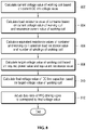
- FIGS. 7 and 8 are flow charts showing a process of driving the induction heating apparatus of one embodiment.
- the main control circuit 20 sets a driving frequency of the inverter circuit 208 to the first predetermined driving frequency (702).
- the first driving frequency may be set to a frequency three times greater than a minimum frequency f min of the inverter circuit 208, i.e., 3 ⁇ f min .
- the inverter circuit 208's minimum frequency f min denotes the inverter circuit 208's driving frequency when the working coil 210's output power value is a minimum value.
- the main control circuit 20 sets the driving frequency of the inverter circuit 208 to the first driving frequency, and provides a control signal corresponding to the first driving frequency to the inverter control circuit 22. Having received the control signal, the inverter control circuit 22 provides a first inverter driving signal S 1 , a second inverter driving signal S 2 , a third inverter driving signal S 3 , and a fourth inverter driving signal S 4 that have a duty ratio corresponding to the first driving frequency, respectively to the first switching element 214, the second switching element 216, the third switching element 218 and the fourth switching element 220.
- the main control circuit 20 calculates a resistance value, i.e., a load resistance value, of the container, using an input voltage value measured by the voltage measurement sensor 24 and an input current value measured by the first current measurement sensor 23 (704).
- P denotes an input power value and is calculated by multiplying the input voltage value V by the input current value I.
- G denotes a predetermined voltage gain value.
- the load resistance value may be calculated, using another method, based on the input voltage value measure by the voltage measurement sensor 24 and the input current value measured by the first current measurement sensor 23.
- the main control circuit 20 compares the calculated load resistance value with a first predetermined reference resistance value K1 (706).
- the first reference resistance value K1 may be set to be the same as Rpot,t,max in [Equation 1] described hereunder.
- R pot , t , max G max ⁇ V in 2 4 P rated
- Gmax denotes a maximum voltage gain value among ratios of output voltages of the inverter circuit 208 to input voltages of the inverter circuit 208, i.e., voltage gain values.
- the maximum voltage gain value may be replaced with a value acquired through an experiment or a previously calculated value.
- Vin denotes an input voltage value measured by the voltage measurement sensor 24.
- Prated denotes maximum rated power of the induction heating apparatus.
- the main control circuit 20 sets the driving mode of the inverter circuit 208 to a three-fold frequency mode (708).
- the main control circuit 20 performs step 802 described below after completion of the setting of the driving mode.
- FIG. 3 shows a wave form of resonance current of the working coil 210, measured by the second current measurement sensor 25, a waveform of bridge voltage Vab that is voltage supplied between an output terminal a and an output terminal b, and waveforms of a first inverter driving signal S 1 , a second inverter driving signal S 2 , a third inverter driving signal S 3 and a fourth inverter driving signal S 4 when the driving mode of the inverter circuit 208 of one embodiment is a three-fold frequency mode.
- the main control circuit 20 supplies a control signal to the inverter control circuit 22 such that the inverter control circuit 22 outputs the first inverter driving signal S 1 , the second inverter driving signal S 2 , the third inverter driving signal S 3 and the fourth inverter driving signal S 4 that have the duty ratios and waveforms illustrated in FIG. 3 .
- the main control circuit 20 sets the resonance current to be output three times for a single period P1 of the first inverter driving signal S 1 , the second inverter driving signal S 2 , the third inverter driving signal S 3 and the fourth inverter driving signal S 4 , as illustrated in FIG. 3 .
- the main control circuit 20 sets the resonance frequency of the working coil 210 to a frequency three times greater than the driving frequency of the inverter circuit 210.
- the main control circuit 20 adjusts the opening and closing states of the switches 233, 234, 236 so that capacitance Cr,t of the variable capacitor circuit 222 can be the same as [Equation 2] described hereunder.
- C r , t 1 2 ⁇ r , t 2 L r
- fr,t denotes a frequency value that is three times greater than the driving frequency of the inverter circuit 208
- Lr denotes inductance of the inductor L 2 .
- the capacitance of the variable capacitor circuit 222 is adjusted to be the same as [Equation 2], and as the first inverter driving signal S 1 , the second inverter driving signal S 2 , the third inverter driving signal S 3 and the fourth inverter driving signal S 4 , illustrated in FIG. 2 , are provided to the inverter circuit 208, the inverter circuit 208 operates in the three-fold frequency mode.
- the main control circuit 20 sets the driving frequency of the inverter circuit 208 to a second predetermined driving frequency (710).
- the second driving frequency may be set to a frequency two times greater than the minimum frequency fmin, i.e., 2 ⁇ f min .
- the main control circuit 20 provides a control signal corresponding to the second driving frequency to the inverter control circuit 22 in the state in the driving frequency of the inverter circuit 208 is set to the second driving frequency.
- the inverter control circuit 22 Having received the control signal, the inverter control circuit 22 provides a first inverter driving signal S 1 , a second inverter driving signal S 2 , a third inverter driving signal S 3 , and a fourth inverter driving signal S 4 that have a duty ratio corresponding to the second driving frequency, respectively to the first switching element 214, the second switching element 216, the third switching element 218 and the fourth switching element 220.
- the main control circuit 20 calculates a resistance value, i.e., a load resistance value, of the container, using an input voltage value measured by the voltage measurement sensor 24 and an input current value measured by the first current measurement sensor 23 (712).
- the main control circuit 20 compares the calculated load resistance value with a second predetermined reference resistance value K2 (714).
- the second reference resistance value K2 may be set to be the same as Rpot,d,max in [Equation 3] described hereunder.
- R pot , d , max G max ⁇ V in 2 4 P rated
- the main control circuit 20 sets the driving mode of the inverter circuit 208 to a two-fold frequency mode (716).
- the main control circuit 20 performs step 802 described below after completion of the setting of the driving mode.
- FIG. 4 shows a wave form of resonance current of the working coil 210, measured by the second current measurement sensor 25, a waveform of bridge voltage Vab that is voltage supplied between the output terminal a and the output terminal b, and waveforms of a first inverter driving signal S 1 , a second inverter driving signal S 2 , a third inverter driving signal S 3 and a fourth inverter driving signal S 4 when the driving mode of the inverter circuit 208 of one embodiment is a two-fold frequency mode.
- the main control circuit 20 supplies a control signal to the inverter control circuit 22 such that the inverter control circuit 22 outputs the first inverter driving signal S 1 , the second inverter driving signal S 2 , the third inverter driving signal S 3 and the fourth inverter driving signal S 4 that have the duty ratios and waveforms illustrated in FIG. 4 .
- the main control circuit 20 sets the resonance current to be output two times for a single period P1 of the first inverter driving signal S 1 , the second inverter driving signal S 2 , the third inverter driving signal S 3 and the fourth inverter driving signal S 4 , as illustrated in FIG. 4 .
- the main control circuit 20 sets the resonance frequency of the working coil 210 to a frequency two times greater than the driving frequency of the inverter circuit 210.
- the main control circuit 20 adjusts the opening and closing states of the switches 233, 234, 236 so that capacitance Cr,d of the variable capacitor circuit 222 can be the same as [Equation 4] described hereunder.
- C r , d 1 2 ⁇ r , d 2 L r
- fr,d denotes a frequency value that is two times greater than the driving frequency of the inverter circuit 208.
- the capacitance of the variable capacitor circuit 222 is adjusted to be the same as [Equation 4], and as the first inverter driving signal S 1 , the second inverter driving signal S 2 , the third inverter driving signal S 3 and the fourth inverter driving signal S 4 , illustrated in FIG. 4 , are provided to the inverter circuit 208, the inverter circuit 208 operates in the two-fold frequency mode.
- the main control circuit 20 sets the driving frequency of the inverter circuit 208 to a third predetermined driving frequency (718).
- the third driving frequency may be set to the minimum frequency fmin.
- the main control circuit 20 provides a control signal corresponding to the third driving frequency to the inverter control circuit 22 in the state in the driving frequency of the inverter circuit 208 is set to the third driving frequency.
- the inverter control circuit 22 Having received the control signal, the inverter control circuit 22 provides a first inverter driving signal S 1 , a second inverter driving signal S 2 , a third inverter driving signal S 3 , and a fourth inverter driving signal S 4 that have a duty ratio corresponding to the third driving frequency, respectively to the first switching element 214, the second switching element 216, the third switching element 218 and the fourth switching element 220.
- the main control circuit 20 calculates a resistance value, i.e., a load resistance value, of the container, using an input voltage value measured by the voltage measurement sensor 24 and an input current value measured by the first current measurement sensor 23 (720).
- the main control circuit 20 compares the calculated load resistance value with a third predetermined reference resistance value K3.
- the third reference resistance value K3 may be set to be the same as Rpot,h,max in [Equation 5] described hereunder.
- R pot , h , max G max ⁇ V in 2 4 P rated
- the main control circuit 20 sets the driving mode of the inverter circuit 208 to a half bridge mode (724).
- the main control circuit 20 performs step 802 described below after completion of the setting of the driving mode.
- FIG. 5 shows a wave form of resonance current of the working coil 210, measured by the second current measurement sensor 25, a waveform of bridge voltage Vab that is voltage supplied between the output terminal a and the output terminal b, and waveforms of a first inverter driving signal S 1 , a second inverter driving signal S 2 , a third inverter driving signal S 3 and a fourth inverter driving signal S 4 when the driving mode of the inverter circuit 208 of one embodiment is a half bridge mode.
- the main control circuit 20 supplies a control signal to the inverter control circuit 22 such that the inverter control circuit 22 outputs the first inverter driving signal S 1 , the second inverter driving signal S 2 , the third inverter driving signal S 3 and the fourth inverter driving signal S 4 that have the duty ratios and waveforms illustrated in FIG. 5 .
- the main control circuit 20 sets the resonance current to be output once for a single period P1 of the first inverter driving signal S 1 , the second inverter driving signal S 2 , the third inverter driving signal S 3 and the fourth inverter driving signal S 4 , as illustrated in FIG. 5 .
- the main control circuit 20 sets the resonance frequency of the working coil 210 to a frequency the same as the driving frequency of the inverter circuit 210.
- the main control circuit 20 adjusts the opening and closing states of the switches 233, 234, 236 so that capacitance Cr,h of the variable capacitor circuit 222 can be the same as [Equation 6] described hereunder.
- C r , h 1 2 ⁇ r , h 2 L r
- fr,h denotes a frequency value that is the same as the driving frequency of the inverter circuit 210.
- the capacitance of the variable capacitor circuit 222 is adjusted to be the same as [Equation 6], and as the first inverter driving signal S 1 , the second inverter driving signal S 2 , the third inverter driving signal S 3 and the fourth inverter driving signal S 4 , illustrated in FIG. 5 , are provided to the inverter circuit 208, the inverter circuit 208 operates in the half bridge mode.
- the main control circuit 20 sets the driving mode to a full bride mode (726).
- the main control circuit 20 performs step 802 described below after completion of the setting of the driving mode.
- FIG. 6 shows a wave form of resonance current of the working coil 210, measured by the second current measurement sensor 25, a waveform of bridge voltage Vab that is voltage supplied between the output terminal a and the output terminal b, and waveforms of a first inverter driving signal S 1 , a second inverter driving signal S 2 , a third inverter driving signal S 3 and a fourth inverter driving signal S 4 when the driving mode of the inverter circuit 208 of one embodiment is a full bridge mode.
- the main control circuit 20 supplies a control signal to the inverter control circuit 22 such that the inverter control circuit 22 outputs the first inverter driving signal S 1 , the second inverter driving signal S 2 , the third inverter driving signal S 3 and the fourth inverter driving signal S 4 that have the duty ratios and waveforms illustrated in FIG. 6 .
- the main control circuit 20 sets the resonance current to be output once for a single period P1 of the first inverter driving signal S 1 , the second inverter driving signal S 2 , the third inverter driving signal S 3 and the fourth inverter driving signal S 4 , as illustrated in FIG. 5 .
- the main control circuit 20 sets the resonance frequency of the working coil 210 to a frequency the same as the driving frequency of the inverter circuit 210.
- the main control circuit 20 adjusts the opening and closing states of the switches 233, 234, 236 so that capacitance Cr,f of the variable capacitor circuit 222 can be the same as [Equation 8] described hereunder.
- C r , f 1 2 ⁇ r , f 2 L r
- fr,f denotes a frequency value that the same as the driving frequency of the inverter circuit 210.
- the capacitance of the variable capacitor circuit 222 is adjusted to be the same as [Equation 8], and as the first inverter driving signal S 1 , the second inverter driving signal S 2 , the third inverter driving signal S 3 and the fourth inverter driving signal S 4 , illustrated in FIG. 6 , are provided to the inverter circuit 208, the inverter circuit 208 operates in the full bridge mode.
- the main control circuit 20 calculates a load resistance value again, and compares the calculated load resistance value with a fourth predetermined reference resistance value K4.
- the fourth reference resistance value K4 may be set to be the same as Rpot,f,max in [Equation 8] described hereunder.
- R pot , f , max G max ⁇ V in 2 P rated
- the main control circuit 20 limits the output power value of the working coil 210 to a value less than a predetermined reference power value. Accordingly, the main control circuit 20 changes the driving frequency of the inverter circuit 208 to a frequency value corresponding to the reference power value, and provides a control signal corresponding to the changed driving frequency to the inverter control circuit 22.
- step 728 when the load resistance value is less than the fourth reference resistance value K4, the driving mode of the inverter circuit 208 remains in the full bridge mode, and the main control circuit 20 performs step 802 described below.
- the main control circuit 20 obtains magnitude of output voltage of the DC link capacitor C 1 , measured through the voltage measurement sensor 24, i.e., a current DC link voltage value.
- the main control circuit 20 calculates a current voltage value of the working coil 210, based on the current DC link voltage value (802).
- the main control circuit 20 may calculate the current voltage value of the working coil 210, based on [Equation 9] described hereunder.
- VC 1 2 2 ⁇ ⁇ 1 2 ⁇ G ⁇ ⁇ VD 1
- VC1 denotes a current voltage value of the working coil 210
- VD1 denotes a current DC link voltage value
- Gv denotes a voltage gain value, and may be replaced with a value acquired through an experiment or a previously calculated value.
- the main control circuit 20 calculates a load resistance value of a container, based on the working coil 210's current voltage value calculated in step 802, and the working coil 210's resonance current value measured through the second current measurement sensor 25 (804).
- Ir denotes a resonance current value measured by the second current measurement sensor 25
- n denotes the number of windings of the working coil 210.
- VC1 denotes the working coil 210's current voltage value calculated in step 802
- Rpot denotes a load resistance value.
- Lm denotes the working coil 210's magnetizing inductance
- T denotes a switching cycle of the inverter circuit 208, i.e., a cycle in which the switching elements of the inverter circuit 208 are turned on/ turned off.
- the main control circuit 20 can calculate a load resistance value Rpot by applying the resonance current value Ir measured by the second current measurement sensor 25, the working coil 210's current voltage value VC1 calculated in step 802, and the number n of windings of the working coil 210 to [Equation 10].
- the main control circuit 20 calculates equivalent resistance values of the container and the working coil, based on the load resistance value calculated in step 804 and the number of windings of the working coil (806). Assuming that the container and the working coil are a single load, the equivalent resistance value is a resistance value of the single load.
- Equation 11 Req denotes an equivalent resistance value, and n denotes the number of windings of the working coil 210. Additionally, Rpot denotes the container's load resistance value calculated in step 804.
- the main control circuit 20 calculates a target voltage value of the working coil 210, based on a required power value required of the working coil 210, corresponding to a heating level set by the user, and the equivalent resistance value calculated in step 806 (808).
- the main control circuit 20 can calculate the target voltage value, based on [Equation 12] described hereunder.
- VC 2 P transfer ⁇ R eq
- VC2 denotes a target voltage value of the working coil 210.
- the main control circuit 20 controls magnitude of voltage supplied to the working coil 210 so that the magnitude of voltage can reach the target voltage value.
- Ptransfer denotes a required power value of the working coil 210
- Req denotes the equivalent resistance value calculated in step 806.
- the main control circuit 20 calculates a final voltage value of the DC link capacitor C 1 , based on the working coil 210's target voltage value calculated in step 808 (810).
- the main control circuit 20 can calculate the final voltage value, based on [Equation 13] described hereunder.
- VD 2 VC 2 ⁇ ⁇ G ⁇ ⁇ 2
- VD2 denotes a final voltage value of the DC link capacitor C 1 .
- VC2 denotes the target voltage value calculated in step 808, and Gv denotes a voltage gain value.
- the main control circuit 20 adjusts a duty ratio of a PFC driving signal S P output from the PFC control circuit 21, based on the calculated final voltage value. Accordingly, magnitude of voltage output from the PFC circuit 206 is adjusted, and a voltage value of voltage output from the DC link capacitor C 1 is adjusted to the final voltage value. Further, as the voltage value of the DC link voltage is adjusted to the final voltage value, an output power value of the working coil 210 reaches the required power value corresponding to the heating level set by the user.
- the induction heating apparatus operates in various modes, depending on characteristics of a container, as described above.
- the induction heating apparatus can ensure a wider operation range, and when it comes to the induction heating apparatus, containers exhibiting various characteristics can be used.
- the induction heating apparatus when the output power of working coil is adjusted, the voltage value of DC link capacitor is adjusted through the PFC circuit, instead of adjusting driving frequency of the induction heating apparatus.
- the induction heating apparatus according to the disclosure which uses a method by which output power is adjusted based on adjustment of a voltage value of the DC link capacitor, ensures higher power efficiency and a wider power adjustment range than an induction heating apparatus of the related art, which uses a method by which output power is adjusted based on adjustment of a frequency.
Landscapes
- Engineering & Computer Science (AREA)
- Power Engineering (AREA)
- Physics & Mathematics (AREA)
- Electromagnetism (AREA)
- Inverter Devices (AREA)
- General Induction Heating (AREA)
- Induction Heating Cooking Devices (AREA)
Abstract
Description
- Disclosed herein is an induction heating apparatus.
- Various types of cooking apparatuses are used at homes or restaurants to heat food items. Gas ranges that use gas as a fuel have been widely used as one of the cooking apparatuses. Currently, apparatuses that heat a cooking container by using electric energy are used.
- Methods in which a container is heated using electric energy include a resistance heating method and an induction heating method. In terms of the resistance heating method, heat energy is generated when electric current flows in a metallic resistance wire or a non-metallic heat generation element such as silicon carbide, the generated heat energy is delivered to a container, and the container is heated. In terms of the induction heating method, a magnetic field is generated around a working coil when electric energy is supplied to the working coil, eddy current is produced in a container by the magnetic field, and the container is heated.
- Induction heating apparatuses include one or more working coils and heat a container using the above-mentioned induction heating method.
FIG. 1 is a schematic circuit diagram of an induction heating apparatus of the related art. - Referring to
FIG. 1 , the induction heating apparatus of the related art includes arectifier circuit 104, smoothing circuits L, C1, aninverter circuit 106, aworking coil 108, amain control circuit 110, and aninverter control circuit 112. - The
rectifier circuit 104 rectifies AC input voltage supplied from apower source 102 and outputs voltage having pulsating waveforms. - The smoothing circuits L, C1 smooth the voltage rectified by the
rectifier circuit 104 and output DC link voltage. The smoothing circuits L, C1 include an inductor L and a DC link capacitor C1. - The
inverter circuit 106 converts the DC link voltage output from the smoothing circuits L, C1 into AC voltage for driving theworking coil 108. Theinverter circuit 106 includes a first capacitor C2, a second capacitor C3, afirst switching element 120, and asecond switching element 122. - The
first switching element 120 and thesecond switching element 122 included in theinverter circuit 106 are alternatively turned on/turned off by a first inverter driving signal S1 and a second inverter driving signal S2 output from theinverter control circuit 112. The first inverter driving signal S1 and the second inverter driving signal S2 are pulse width modulation (PWM) signals that respectively have a predetermined duty ratio. As the first inverter driving signal S1 and the second inverter driving signal S2 are supplied respectively to thefirst switching element 120 and thesecond switching element 122, the DC link voltage is converted into AC voltage while thefirst switching element 120 and thesecond switching element 122 are alternatively turned on/turned off. - The AC voltage output from the
inverter circuit 106 is supplied to theworking coil 108. As the AC voltage is supplied, theworking coil 108 operates. As theworking coil 108 operates, a container placed on theworking coil 108 is heated while eddy current flows in the container. Magnitude of thermal energy supplied to the container varies depending on magnitude of power generated by theworking coil 108 during the driving of theworking coil 108, i.e., an output power value of the working coil. - The
main control circuit 110 determines a driving frequency of theinverter circuit 106, and provides a control signal corresponding to the determined driving frequency to theinverter control circuit 112. Thus, theinverter control circuit 112 outputs inverter driving signals S1, S2 having duty ratios corresponding to the driving frequency determined by themain control circuit 110. - A user places a container on the working
coil 108 of the induction heating apparatus, and sets a heating level for the container. Based on the heating level set by the user, an output power value required of theworking coil 108, i.e., a required power value, is determined. For example, when the user sets the heating level to 5, the required power value of theworking coil 108 is determined as 4 kW that is a power value corresponding to heating level 5. - The
main control circuit 110 provides a control signal to theinverter control circuit 112 while changing the driving frequency of theinverter circuit 106 until the output power value of theworking coil 108 reaches the required power value (e.g., 4 kW). As the output power value of theworking coil 108 reaches the required power value, the driving frequency of theinverter circuit 106 is fixed. - However, in the related art, because of characteristics of the elements included in the induction heating apparatus, a range of driving frequencies of the
inverter circuit 106 is limited to a specific range. Due to a limited range of driving frequencies, limited sorts of containers can be used for the induction heating apparatus. That is, it is difficult to use containers for the induction heating apparatus of the related art, regardless of materials or characteristics of the containers. - Additionally, in the related art, the driving frequency of the
inverter circuit 106 changes until the output power value of theworking coil 108 reaches the required power value. However, each time the driving frequency of theinverter circuit 106 changes, conduction loss of theswitching elements inverter circuit 106 occurs, and an amount of heat generated in theworking coil 108 increases, and impedance of a container, i.e., load impedance, changes. Thus, power efficiency of the workingcoil 108 decreases, and easy of control over a heating operation of the induction heating apparatus deteriorates. - One objective of the present disclosure is to provide an induction heating apparatus where a container made of different materials or having different characteristics can be used.
- Another objective of the present disclosure is to provide an induction heating apparatus that can adjust an output power value of a working coil with no need to change a driving frequency of an inverter circuit.
- Yet another objective of the present disclosure is to provide an induction heating apparatus that can ensure power efficiency higher than that of an induction heating apparatus of the related art and ease of control over a heating operation.
- Aspects according to the present disclosure are not limited to the above ones, and other aspects and advantages that are not mentioned above can be clearly understood from the following description and can be more clearly understood from the embodiments set forth herein. Additionally, the aspects and advantages in the present disclosure can be realized via means and combinations thereof that are described in the appended claims.
- An induction heating apparatus of one embodiment includes a rectifier circuit configured to rectify AC input voltage supplied by a power source and outputting the rectified voltage, a PFC circuit configured to be driven by a PFC driving signal and controlling and outputting power factors of the rectified voltage and current, a DC link capacitor configured to smooth voltage output from the PFC circuit and outputting DC link voltage, an inverter circuit including a first switching element, a second switching element, a third switching element, a fourth switching element and a variable capacitor circuit, and being driven by an inverter driving signal and converting the DC link voltage into AC voltage for driving a working coil, and a main control circuit adjusting capacitance of the variable capacitor circuit depending on a driving mode of the inverter circuit determined based on a load resistance value of a container placed on the working coil, and adjusting magnitude of the DC link voltage depending on a final voltage value calculated based on equivalent resistance values of the container and the working coil and a required power value of the working coil.
- In one embodiment, the main control circuit calculates a current voltage value of the working coil based on a current DC link voltage value, calculates a load resistance value of the container based on the current voltage value of the working coil and a resonance current value of the working coil, and calculates the equivalent resistance values based on the load resistance value and the number of windings of the working coil.
- In one embodiment, the main control circuit calculates a target voltage value of the working coil based on the required power value and the equivalent resistance value, and calculates the final voltage value based on the target voltage value.
- In one embodiment, the main control circuit adjusts a duty ratio of the PFC driving signal so that the duty ratio can correspond to the final voltage value.
- In one embodiment, the PFC circuit includes a boost inductor, a diode connected in series with the boost inductor, and a boost switching element connected in parallel with a connection point between the boost inductor and the diode.
- In one embodiment, the main control circuit compares the load resistance value with a predetermined reference resistance value, and based on results of the comparison, determines a driving mode of the inverter circuit.
- In one embodiment, the main control circuit sets the driving mode to a three-fold frequency mode when the load resistance value is less than a first predetermined reference resistance value in a state in which a driving frequency of the inverter circuit is set to a first predetermined driving frequency.
- In one embodiment, the main control circuit sets the driving mode to a two-fold frequency mode when the load resistance value is less than a second predetermined reference resistance value in a state in which a driving frequency of the inverter circuit is set to a first predetermined driving frequency.
- In one embodiment, the main control circuit sets the driving mode to a half bridge mode when the load resistance value is less than a third predetermined reference resistance value in a state in which a driving frequency of the inverter circuit is set to a third predetermined driving frequency.
- In one embodiment, the main control circuit sets the driving mode to a full bridge mode when the load resistance value is greater than or equal to a third predetermined reference resistance value in a state in which a driving frequency of the inverter circuit is set to a third predetermined driving frequency.
- In one embodiment, the main control circuit limits an output power value of the working coil to a value that is a predetermined reference power value or less, when the load resistance value is greater than or equal to a fourth predetermined reference resistance value in a state in which the driving mode is set to a full bridge mode.
- In an induction heating apparatus according to the present disclosure, a container made of different materials or having different characteristics can be used.
- In the induction heating apparatus according to the present disclosure, an output power value of a working coil can be adjusted with no need to change a driving frequency of an inverter circuit.
- Unlike an induction heating apparatus of the related art, the induction heating apparatus according to the present disclosure can ensure high power efficiency and ease of control over a heating operation.
-
-
FIG. 1 is a circuit diagram of an induction heating apparatus of the related art. -
FIG. 2 is a circuit diagram of an induction heating apparatus of one embodiment. -
FIG. 3 is a view showing a wave form of resonance current of a working coil, a waveform of bridge voltage, and waveforms of inverter driving signals when the induction heating apparatus of one embodiment operates in a three-fold frequency mode. -
FIG. 4 is a view showing a waveform of resonance current of a working coil, a waveform of bridge voltage, and waveforms of inverter driving signals when the induction heating apparatus of one embodiment operates in a two-fold frequency mode. -
FIG. 5 is a view showing a waveform of resonance current of a working coil, a waveform of bridge voltage, and waveforms of inverter driving signals when the induction heating apparatus of one embodiment operates in a half bridge mode. -
FIG. 6 is a view showing a waveform of resonance current of a working coil, a waveform of bridge voltage, and waveforms of inverter driving signals when the induction heating apparatus of one embodiment operates in a full bridge mode. -
FIGs. 7 and8 are flow charts showing a driving process of the induction heating apparatus of one embodiment. - The above-described aspects, features and advantages are specifically described hereunder with reference to the accompanying drawings so that one having ordinary skill in the art to which the present disclosure pertains can easily implement the technical spirit of the disclosure. In the disclosure, detailed description of known technologies in relation to the disclosure is omitted if it is deemed to make the gist of the disclosure unnecessarily vague. Below, preferred embodiments according to the disclosure are specifically described with reference to the accompanying drawings. In the drawings, identical reference numerals can denote identical or similar components.
-
FIG. 2 is a circuit diagram of an induction heating apparatus of one embodiment. - Referring to
FIG. 2 , the induction heating apparatus of one embodiment includes arectifier circuit 204, a power factor correction (PFC)circuit 206, aninverter circuit 208, a workingcoil 210, amain control circuit 20, aPFC control circuit 21, and aninverter control circuit 22. - The
rectifier circuit 204 rectifies AC input voltage supplied from apower source 202, and outputs voltage having pulsating waveforms. Therectifier circuit 204 may include one or more diodes. - The
PFC circuit 206 controls power factors of rectified voltage and current output from therectifier circuit 204. That is, thePFC circuit 206 removes harmonic components included in the current output from therectifier circuit 204, and reduces a phase difference between the current and the voltage that are output from therectifier circuit 204 and controls the power factors of the rectified voltage and current. - The
PFC circuit 206 includes a boost inductor L1, a diode D connected in series with the boost inductor L1, and aboost switching element 212 connected in parallel with a connection point between the boost inductor L1 and the diode D. - The
boost switching element 212 is turned on/turned off by a PFC driving signal SP output from thePFC control circuit 21. The PFC driving signal SP is a PWM signal having a predetermined duty ratio. As described below, the duty ratio of the PFC driving signal SP may be adjusted by themain control circuit 20, and thePFC control circuit 21 outputs a PFC driving signal SP having a duty ratio set by themain control circuit 20. - Magnitude of voltage output from the
PFC circuit 206 varies, depending on a duty ratio of the PFC driving signal SP. Additionally, magnitude of voltage output from a DC link capacitor C1, i.e., DC link voltage, varies depending on magnitude of voltage output from thePFC circuit 206. - Referring back to
FIG. 2 , the DC link capacitor C1 connected to thePFC circuit 206 smoothes voltage output from thePFC circuit 206 and outputs DC link voltage. - The
inverter circuit 208 converts the DC link voltage output from the DC link capacitor C1 into AC voltage for driving the workingcoil 210. Theinverter circuit 208 includes afirst switching element 214, asecond switching element 216, athird switching element 218, afourth switching element 220, an inductor L2 and avariable capacitor circuit 222. - The
first switching element 214, thesecond switching element 216, thethird switching element 218, and thefourth switching element 220 that are included in theinverter circuit 106 are turned on/turned off alternatively by a first inverter driving signal S1, a second inverter driving signal S2, a third inverter driving signal S3, and a fourth inverter driving signal S4 that are output from aninverter control circuit 112. The first inverter driving signal S1, the second inverter driving signal S2, the third inverter driving signal S3, and the fourth inverter driving signal S4 are respectively a PWM signal having a predetermined duty ratio. As the first inverter driving signal S1, the second inverter driving signal S2, the third inverter driving signal S3, and the fourth inverter driving signal S4 are respectively supplied to thefirst switching element 214, thesecond switching element 216, thethird switching element 218, and thefourth switching element 220, thefirst switching element 214 and thesecond switching element 216 are alternatively turned on/turned off, and thethird switching element 218 and thefourth switching element 220 are alternatively turned on/turned off. - In the disclosure, duty ratios or waveforms of the first inverter driving signal S1, the second inverter driving signal S2, the third inverter driving signal S3, and the fourth inverter driving signal S4 may be set differently depending on a driving mode and a driving frequency of the
inverter circuit 106. As described below, themain control circuit 20 determines a driving mode of theinverter circuit 106 depending on characteristics of a container, and a driving frequency of theinverter circuit 106 may be set differently depending on a driving mode of theinverter circuit 106. - AC voltage output from the
inverter circuit 208 is supplied to the workingcoil 210. As the AC voltage is supplied to the workingcoil 210, the workingcoil 210 operates. As the workingcoil 210 operates, a container placed on the workingcoil 210 is heated while eddy current flows in the container. Magnitude of thermal energy supplied to the container varies depending on magnitude of power that is generated by the workingcoil 210 when the workingcoil 210 operates, i.e., an output power value of the workingcoil 210. - The
variable capacitor circuit 222 includes a first capacitor C2, a second capacitor C3 and a third capacitor C4 that connect to one another in parallel, and a first switch 233, asecond switch 234 and athird switch 236 that connect respectively to the capacitors in series. The first switch 233, thesecond switch 234 and thethird switch 236 can be respectively opened and closed by a control signal of themain control circuit 20. Capacitance of thevariable capacitor circuit 222 may vary depending on the opening and closing state of the first switch 233, thesecond switch 234 and thethird switch 236. -
FIG. 2 shows that thevariable capacitor circuit 222 includes three capacitors, for example. However, the number of capacitors included in thevariable capacitor circuit 222 and a circuit structure may vary depending on embodiment. - As AC voltage is supplied to the working
coil 210, resonance is induced by capacitors included in the inductor L2 and thevariable capacitor circuit 222. As is known, when resonance occurs in an LC circuit, a resonance frequency varies depending on magnitude of inductance and magnitude of capacitance. Amain control circuit 110 of the induction heating apparatus according to the present disclosure controls the opening and closing states of theswitches variable capacitor circuit 222 to adjust magnitude of capacitance of thevariable capacitor circuit 222. As the magnitude of the capacitance of thevariable capacitor circuit 222 is adjusted, a resonance frequency of the workingcoil 210 can be adjusted. - The
main control circuit 20 determines a driving mode of theinverter circuit 106, and supplies a control signal corresponding to the determined driving mode to theinverter control circuit 22. Theinverter control circuit 22 outputs an inverter driving signal S1, S2, S3, S4 having a duty ratio or a waveform corresponding to the driving mode determined by themain control circuit 110. - As a user places a container on the working
coil 210 of the induction heating apparatus and set a heating level for the container, an output power value required of the workingcoil 210, i.e., a required power value, is determined based on the heating level set by the user. For example, when the user sets the heating level to 5, the required power value of the workingcoil 210 is determined as 4 kW that is a power value corresponding to heating level 5. - In this case, the container placed on the working
coil 210 has different characteristics depending on a material of the container. Themain control circuit 20 calculates a resistance value representing the characteristics of the container placed on the workingcoil 210, i.e., a load resistance value, and based on the calculated load resistance value, determines a driving mode of aninverter circuit 208. As the driving mode of theinverter circuit 208 is determined, a driving frequency of theinverter circuit 208 is determined. - In one embodiment, the
main control circuit 20 can calculate a load resistance value, based on an input voltage value measured by avoltage measurement sensor 24 and an input current value measured by a firstcurrent measurement sensor 23. - In one embodiment, the
main control circuit 20 compares the load resistance value with a predetermined reference resistance value, and based on results of the comparison, determines a driving mode of theinverter circuit 208. - In one embodiment, when the load resistance value is less than a first predetermined reference resistance value in a state in which the driving frequency of the
inverter circuit 208 is set to a first predetermined driving frequency, themain control circuit 20 sets the driving mode of theinverter circuit 208 to a three-fold frequency mode. - Additionally, in one embodiment, when the load resistance value is less than a second predetermined reference resistance value in the state in which the driving frequency of the
inverter circuit 208 is set to the first predetermined driving frequency, themain control circuit 20 sets the driving mode of theinverter circuit 208 to a two-fold frequency mode. - Further, in one embodiment, when the load resistance value is less than a third predetermined reference resistance value in a state in which the driving frequency of the
inverter circuit 208 is set to a third predetermined driving frequency, themain control circuit 20 sets the driving mode of theinverter circuit 208 to a half bridge mode. - Further, in one embodiment, when the load resistance value is greater than or equal to the third predetermined reference resistance value in the state in which the driving frequency of the
inverter circuit 208 is set to the third predetermined driving frequency, themain control circuit 20 sets the driving mode of theinverter circuit 208 to a full bridge mode. - Furthermore, in one embodiment, when the load resistance value is greater than or equal to a fourth predetermined reference resistance value in the state in which the driving mode of the
inverter circuit 208 is set to the full bridge mode, themain control circuit 20 limits the output power value of the workingcoil 210 to a value less than a predetermined reference power value. - The
main control circuit 20 provides a control signal based on the determined driving mode and driving frequency to theinverter control circuit 22. Theinverter control circuit 22 provides inverter driving signals S1 ,S2, S3 ,S4 having duty ratios and waveforms corresponding to the driving mode determined by themain control circuit 20 respectively to the switchingelements - In the disclosure, since the induction heating apparatus's driving mode appropriate for a container placed on the working
coil 210 is determined as described above, a container made of different materials can be used. - When the driving mode is determined and then the
inverter circuit 208 operates, themain control circuit 20 adjusts the workingcoil 210's output power value so that the workingcoil 210's output power value can reach the workingcoil 210's required power value corresponding to a heating level set by the user. Themain control circuit 20 according to the disclosure adjusts a voltage value of DC link voltage output from the DC link capacitor C1 rather than theinverter circuit 208's driving frequency, to adjust the workingcoil 210's output power value, unlike that of the related art. - In one embodiment, the
main control circuit 20 calculates a final voltage value, based on an equivalent resistance value that is a resistance value at which resistance of a container and resistance of the workingcoil 210 are added and the required power value of the workingcoil 210. Based on the calculated final voltage value, themain control circuit 20 adjusts a duty ratio of a PFC driving signal SP output from thePFC control circuit 21. Accordingly, magnitude of voltage output from thePFC circuit 206 is adjusted, and the voltage value of the DC link voltage is adjusted to the final voltage value. Additionally, since the voltage value of the DC link voltage is adjusted to the final voltage value, the output power value of the workingcoil 210 reaches the required power value. - In one embodiment, the
main control circuit 20 calculates a current voltage value of the workingcoil 210, based on magnitude of DC link voltage measured by thevoltage measurement sensor 24, i.e., a current DC link voltage value. Themain control circuit 20 calculates a load resistance value of a container, based on the workingcoil 210's current voltage value, and based on the workingcoil 210's resonance current value measured by a secondcurrent measurement sensor 25, and calculates an equivalent resistance value, based on the load resistance value and the number of windings of the working coil. - Additionally, in one embodiment, the
main control circuit 20 calculates a target voltage value of the workingcoil 210, based on the required power value and the equivalent resistance value, and calculates a final voltage value, based on the target voltage value. - Further, in one embodiment, the
main control circuit 20 adjusts a duty ratio of a PFC driving signal SP so that the duty ratio of the PFC driving signal can correspond to the final voltage value. - Hereafter, a process of driving the induction heating apparatus of one embodiment is described with reference to
FIGS. 2 to 8 . -
FIG. 3 is a view showing a waveform of resonance current of a working coil, a waveform of bridge voltage, and waveforms of inverter driving signals when the induction heating apparatus of one embodiment operates in a three-fold frequency mode.FIG. 4 is a view showing a waveform of resonance current of a working coil, a waveform of bridge voltage, and waveforms of inverter driving signals when the induction heating apparatus of one embodiment operates in a two-fold frequency mode.FIG. 5 is a view showing a waveform of resonance current of a working coil, a waveform of bridge voltage, and waveforms of inverter driving signals when the induction heating apparatus of one embodiment operates in a half bridge mode.FIG. 6 is a view showing a waveform of resonance current of a working coil, a waveform of bridge voltage, and waveforms of inverter driving signals when the induction heating apparatus of one embodiment operates in a full bridge mode.FIGS. 7 and8 are flow charts showing a process of driving the induction heating apparatus of one embodiment. - Referring to
FIG. 7 , as the user sets a heating level and then performance of a heating operation is requested in a state in which a container is placed on the workingcoil 210, themain control circuit 20 sets a driving frequency of theinverter circuit 208 to the first predetermined driving frequency (702). - In one embodiment, the first driving frequency may be set to a frequency three times greater than a minimum frequency fmin of the
inverter circuit 208, i.e., 3×fmin. Theinverter circuit 208's minimum frequency fmin denotes theinverter circuit 208's driving frequency when the workingcoil 210's output power value is a minimum value. - The
main control circuit 20 sets the driving frequency of theinverter circuit 208 to the first driving frequency, and provides a control signal corresponding to the first driving frequency to theinverter control circuit 22. Having received the control signal, theinverter control circuit 22 provides a first inverter driving signal S1, a second inverter driving signal S2, a third inverter driving signal S3, and a fourth inverter driving signal S4 that have a duty ratio corresponding to the first driving frequency, respectively to thefirst switching element 214, thesecond switching element 216, thethird switching element 218 and thefourth switching element 220. - As the
inverter circuit 208 is driven by the inverter driving signals and then AC voltage is supplied to the workingcoil 210, themain control circuit 20 calculates a resistance value, i.e., a load resistance value, of the container, using an input voltage value measured by thevoltage measurement sensor 24 and an input current value measured by the first current measurement sensor 23 (704). - For example, the
main control circuit 20 may calculate the load resistance value R, using Equation R=(G×V2)/P. Herein, P denotes an input power value and is calculated by multiplying the input voltage value V by the input current value I. Additionally, G denotes a predetermined voltage gain value. Depending on embodiments, the load resistance value may be calculated, using another method, based on the input voltage value measure by thevoltage measurement sensor 24 and the input current value measured by the firstcurrent measurement sensor 23. - The
main control circuit 20 compares the calculated load resistance value with a first predetermined reference resistance value K1 (706). In one embodiment, the first reference resistance value K1 may be set to be the same as Rpot,t,max in [Equation 1] described hereunder.
- In [Equation 1], Gmax denotes a maximum voltage gain value among ratios of output voltages of the
inverter circuit 208 to input voltages of theinverter circuit 208, i.e., voltage gain values. The maximum voltage gain value may be replaced with a value acquired through an experiment or a previously calculated value. - Additionally, Vin denotes an input voltage value measured by the
voltage measurement sensor 24. Further, Prated denotes maximum rated power of the induction heating apparatus. - When the calculated load resistance value is less the first reference resistance value K1 as a result of the comparison between the load resistance value and the first reference resistance value K1, the
main control circuit 20 sets the driving mode of theinverter circuit 208 to a three-fold frequency mode (708). Themain control circuit 20 performsstep 802 described below after completion of the setting of the driving mode. -
FIG. 3 shows a wave form of resonance current of the workingcoil 210, measured by the secondcurrent measurement sensor 25, a waveform of bridge voltage Vab that is voltage supplied between an output terminal a and an output terminal b, and waveforms of a first inverter driving signal S1, a second inverter driving signal S2, a third inverter driving signal S3 and a fourth inverter driving signal S4 when the driving mode of theinverter circuit 208 of one embodiment is a three-fold frequency mode. - As the driving mode of the induction heating apparatus is determined as the three-fold frequency mode as described above, the
main control circuit 20 supplies a control signal to theinverter control circuit 22 such that theinverter control circuit 22 outputs the first inverter driving signal S1, the second inverter driving signal S2, the third inverter driving signal S3 and the fourth inverter driving signal S4 that have the duty ratios and waveforms illustrated inFIG. 3 . - Herein, the
main control circuit 20 sets the resonance current to be output three times for a single period P1 of the first inverter driving signal S1, the second inverter driving signal S2, the third inverter driving signal S3 and the fourth inverter driving signal S4, as illustrated inFIG. 3 . In other words, themain control circuit 20 sets the resonance frequency of the workingcoil 210 to a frequency three times greater than the driving frequency of theinverter circuit 210. To this end, themain control circuit 20 adjusts the opening and closing states of theswitches variable capacitor circuit 222 can be the same as [Equation 2] described hereunder.
- In [Equation 2], fr,t denotes a frequency value that is three times greater than the driving frequency of the
inverter circuit 208, and Lr denotes inductance of the inductor L2. - Depending on the adjustment of the opening and closing states of the
switches variable capacitor circuit 222, the capacitance of thevariable capacitor circuit 222 is adjusted to be the same as [Equation 2], and as the first inverter driving signal S1, the second inverter driving signal S2, the third inverter driving signal S3 and the fourth inverter driving signal S4, illustrated inFIG. 2 , are provided to theinverter circuit 208, theinverter circuit 208 operates in the three-fold frequency mode. - Referring back to
FIG. 7 , when the calculated load resistance value is greater than or equal to the first reference resistance value K1 as a result of the comparison between the load resistance value and the first reference resistance value K1, themain control circuit 20 sets the driving frequency of theinverter circuit 208 to a second predetermined driving frequency (710). In one embodiment, the second driving frequency may be set to a frequency two times greater than the minimum frequency fmin, i.e., 2×fmin. - The
main control circuit 20 provides a control signal corresponding to the second driving frequency to theinverter control circuit 22 in the state in the driving frequency of theinverter circuit 208 is set to the second driving frequency. Having received the control signal, theinverter control circuit 22 provides a first inverter driving signal S1, a second inverter driving signal S2, a third inverter driving signal S3, and a fourth inverter driving signal S4 that have a duty ratio corresponding to the second driving frequency, respectively to thefirst switching element 214, thesecond switching element 216, thethird switching element 218 and thefourth switching element 220. - As the
inverter circuit 208 is driven by the inverter driving signals and then AC voltage is supplied to the workingcoil 210, themain control circuit 20 calculates a resistance value, i.e., a load resistance value, of the container, using an input voltage value measured by thevoltage measurement sensor 24 and an input current value measured by the first current measurement sensor 23 (712). - The
main control circuit 20 compares the calculated load resistance value with a second predetermined reference resistance value K2 (714). In one embodiment, the second reference resistance value K2 may be set to be the same as Rpot,d,max in [Equation 3] described hereunder.
- When the calculated load resistance value is less the second reference resistance value K2 as a result of the comparison between the load resistance value and the second reference resistance value K2, the
main control circuit 20 sets the driving mode of theinverter circuit 208 to a two-fold frequency mode (716). Themain control circuit 20 performsstep 802 described below after completion of the setting of the driving mode. -
FIG. 4 shows a wave form of resonance current of the workingcoil 210, measured by the secondcurrent measurement sensor 25, a waveform of bridge voltage Vab that is voltage supplied between the output terminal a and the output terminal b, and waveforms of a first inverter driving signal S1, a second inverter driving signal S2, a third inverter driving signal S3 and a fourth inverter driving signal S4 when the driving mode of theinverter circuit 208 of one embodiment is a two-fold frequency mode. - As the driving mode of the induction heating apparatus is determined as the two-fold frequency mode as described above, the
main control circuit 20 supplies a control signal to theinverter control circuit 22 such that theinverter control circuit 22 outputs the first inverter driving signal S1, the second inverter driving signal S2, the third inverter driving signal S3 and the fourth inverter driving signal S4 that have the duty ratios and waveforms illustrated inFIG. 4 . - Herein, the
main control circuit 20 sets the resonance current to be output two times for a single period P1 of the first inverter driving signal S1, the second inverter driving signal S2, the third inverter driving signal S3 and the fourth inverter driving signal S4, as illustrated inFIG. 4 . In other words, themain control circuit 20 sets the resonance frequency of the workingcoil 210 to a frequency two times greater than the driving frequency of theinverter circuit 210. To this end, themain control circuit 20 adjusts the opening and closing states of theswitches variable capacitor circuit 222 can be the same as [Equation 4] described hereunder.
- In [Equation 4], fr,d denotes a frequency value that is two times greater than the driving frequency of the
inverter circuit 208. - Depending on the adjustment of the opening and closing states of the
switches variable capacitor circuit 222, the capacitance of thevariable capacitor circuit 222 is adjusted to be the same as [Equation 4], and as the first inverter driving signal S1, the second inverter driving signal S2, the third inverter driving signal S3 and the fourth inverter driving signal S4, illustrated inFIG. 4 , are provided to theinverter circuit 208, theinverter circuit 208 operates in the two-fold frequency mode. - Referring back to
FIG. 7 , when the calculated load resistance value is greater than or equal to the second reference resistance value K2 as a result of the comparison between the load resistance value and the second reference resistance value K2, themain control circuit 20 sets the driving frequency of theinverter circuit 208 to a third predetermined driving frequency (718). In one embodiment, the third driving frequency may be set to the minimum frequency fmin. - The
main control circuit 20 provides a control signal corresponding to the third driving frequency to theinverter control circuit 22 in the state in the driving frequency of theinverter circuit 208 is set to the third driving frequency. Having received the control signal, theinverter control circuit 22 provides a first inverter driving signal S1, a second inverter driving signal S2, a third inverter driving signal S3, and a fourth inverter driving signal S4 that have a duty ratio corresponding to the third driving frequency, respectively to thefirst switching element 214, thesecond switching element 216, thethird switching element 218 and thefourth switching element 220. - As the
inverter circuit 208 is driven by the inverter driving signals and then AC voltage is supplied to the workingcoil 210, themain control circuit 20 calculates a resistance value, i.e., a load resistance value, of the container, using an input voltage value measured by thevoltage measurement sensor 24 and an input current value measured by the first current measurement sensor 23 (720). - The
main control circuit 20 compares the calculated load resistance value with a third predetermined reference resistance value K3. In one embodiment, the third reference resistance value K3 may be set to be the same as Rpot,h,max in [Equation 5] described hereunder.
- When the calculated load resistance value is less the third reference resistance value K3 as a result of the comparison between the load resistance value and the third reference resistance value K3, the
main control circuit 20 sets the driving mode of theinverter circuit 208 to a half bridge mode (724). Themain control circuit 20 performsstep 802 described below after completion of the setting of the driving mode. -
FIG. 5 shows a wave form of resonance current of the workingcoil 210, measured by the secondcurrent measurement sensor 25, a waveform of bridge voltage Vab that is voltage supplied between the output terminal a and the output terminal b, and waveforms of a first inverter driving signal S1, a second inverter driving signal S2, a third inverter driving signal S3 and a fourth inverter driving signal S4 when the driving mode of theinverter circuit 208 of one embodiment is a half bridge mode. - As the driving mode of the
inverter circuit 208 is determined as the half bridge mode as described above, themain control circuit 20 supplies a control signal to theinverter control circuit 22 such that theinverter control circuit 22 outputs the first inverter driving signal S1, the second inverter driving signal S2, the third inverter driving signal S3 and the fourth inverter driving signal S4 that have the duty ratios and waveforms illustrated inFIG. 5 . - Herein, the
main control circuit 20 sets the resonance current to be output once for a single period P1 of the first inverter driving signal S1, the second inverter driving signal S2, the third inverter driving signal S3 and the fourth inverter driving signal S4, as illustrated inFIG. 5 . In other words, themain control circuit 20 sets the resonance frequency of the workingcoil 210 to a frequency the same as the driving frequency of theinverter circuit 210. To this end, themain control circuit 20 adjusts the opening and closing states of theswitches variable capacitor circuit 222 can be the same as [Equation 6] described hereunder.
- In [Equation 6], fr,h denotes a frequency value that is the same as the driving frequency of the
inverter circuit 210. - Depending on the adjustment of the opening and closing states of the
switches variable capacitor circuit 222, the capacitance of thevariable capacitor circuit 222 is adjusted to be the same as [Equation 6], and as the first inverter driving signal S1, the second inverter driving signal S2, the third inverter driving signal S3 and the fourth inverter driving signal S4, illustrated inFIG. 5 , are provided to theinverter circuit 208, theinverter circuit 208 operates in the half bridge mode. - Referring back to
FIG. 7 , when the calculated load resistance value is greater than or equal to the third reference resistance value K3 as a result of the comparison between the load resistance value and the third reference resistance value K3, themain control circuit 20 sets the driving mode to a full bride mode (726). Themain control circuit 20 performsstep 802 described below after completion of the setting of the driving mode. -
FIG. 6 shows a wave form of resonance current of the workingcoil 210, measured by the secondcurrent measurement sensor 25, a waveform of bridge voltage Vab that is voltage supplied between the output terminal a and the output terminal b, and waveforms of a first inverter driving signal S1, a second inverter driving signal S2, a third inverter driving signal S3 and a fourth inverter driving signal S4 when the driving mode of theinverter circuit 208 of one embodiment is a full bridge mode. - As the driving mode of the
inverter circuit 208 is determined as the full bridge mode as described above, themain control circuit 20 supplies a control signal to theinverter control circuit 22 such that theinverter control circuit 22 outputs the first inverter driving signal S1, the second inverter driving signal S2, the third inverter driving signal S3 and the fourth inverter driving signal S4 that have the duty ratios and waveforms illustrated inFIG. 6 . - Herein, the
main control circuit 20 sets the resonance current to be output once for a single period P1 of the first inverter driving signal S1, the second inverter driving signal S2, the third inverter driving signal S3 and the fourth inverter driving signal S4, as illustrated inFIG. 5 . In other words, themain control circuit 20 sets the resonance frequency of the workingcoil 210 to a frequency the same as the driving frequency of theinverter circuit 210. To this end, themain control circuit 20 adjusts the opening and closing states of theswitches variable capacitor circuit 222 can be the same as [Equation 8] described hereunder.
- In [Equation 7], fr,f denotes a frequency value that the same as the driving frequency of the
inverter circuit 210. - Depending on the adjustment of the opening and closing states of the
switches variable capacitor circuit 222, the capacitance of thevariable capacitor circuit 222 is adjusted to be the same as [Equation 8], and as the first inverter driving signal S1, the second inverter driving signal S2, the third inverter driving signal S3 and the fourth inverter driving signal S4, illustrated inFIG. 6 , are provided to theinverter circuit 208, theinverter circuit 208 operates in the full bridge mode. - Then the
main control circuit 20 calculates a load resistance value again, and compares the calculated load resistance value with a fourth predetermined reference resistance value K4. In one embodiment, the fourth reference resistance value K4 may be set to be the same as Rpot,f,max in [Equation 8] described hereunder.
- When the load resistance value is greater than or equal to the fourth reference resistance value K4 as a result of the comparison between the fourth reference resistance value K4 and the load resistance value that is calculated after the driving mode of the
inverter circuit 208 is set to the full bridge mode, themain control circuit 20 limits the output power value of the workingcoil 210 to a value less than a predetermined reference power value. Accordingly, themain control circuit 20 changes the driving frequency of theinverter circuit 208 to a frequency value corresponding to the reference power value, and provides a control signal corresponding to the changed driving frequency to theinverter control circuit 22. - In
step 728, when the load resistance value is less than the fourth reference resistance value K4, the driving mode of theinverter circuit 208 remains in the full bridge mode, and themain control circuit 20 performsstep 802 described below. - Referring to
FIG. 8 , afterstep main control circuit 20 obtains magnitude of output voltage of the DC link capacitor C1, measured through thevoltage measurement sensor 24, i.e., a current DC link voltage value. Themain control circuit 20 calculates a current voltage value of the workingcoil 210, based on the current DC link voltage value (802). Themain control circuit 20 may calculate the current voltage value of the workingcoil 210, based on [Equation 9] described hereunder.
- In [Equation 9], VC1 denotes a current voltage value of the working
coil 210, and VD1 denotes a current DC link voltage value. Additionally, Gv denotes a voltage gain value, and may be replaced with a value acquired through an experiment or a previously calculated value. - Then the
main control circuit 20 calculates a load resistance value of a container, based on the workingcoil 210's current voltage value calculated instep 802, and the workingcoil 210's resonance current value measured through the second current measurement sensor 25 (804). Themain control circuit 20 may calculate the load resistance value, based on [Equation 10] described hereunder.
- In [Equation 10], Ir denotes a resonance current value measured by the second
current measurement sensor 25, and n denotes the number of windings of the workingcoil 210. Additionally, VC1 denotes the workingcoil 210's current voltage value calculated instep 802, and Rpot denotes a load resistance value. Further, Lm denotes the workingcoil 210's magnetizing inductance, and T denotes a switching cycle of theinverter circuit 208, i.e., a cycle in which the switching elements of theinverter circuit 208 are turned on/ turned off. Themain control circuit 20 can calculate a load resistance value Rpot by applying the resonance current value Ir measured by the secondcurrent measurement sensor 25, the workingcoil 210's current voltage value VC1 calculated instep 802, and the number n of windings of the workingcoil 210 to [Equation 10]. - Then the
main control circuit 20 calculates equivalent resistance values of the container and the working coil, based on the load resistance value calculated instep 804 and the number of windings of the working coil (806). Assuming that the container and the working coil are a single load, the equivalent resistance value is a resistance value of the single load. Themain control circuit 20 can calculate the equivalent resistance value, based on [Equation 11] described hereunder.
- In [Equation 11], Req denotes an equivalent resistance value, and n denotes the number of windings of the working
coil 210. Additionally, Rpot denotes the container's load resistance value calculated instep 804. - Then the
main control circuit 20 calculates a target voltage value of the workingcoil 210, based on a required power value required of the workingcoil 210, corresponding to a heating level set by the user, and the equivalent resistance value calculated in step 806 (808). Themain control circuit 20 can calculate the target voltage value, based on [Equation 12] described hereunder.
- In [Equation 12], VC2 denotes a target voltage value of the working
coil 210. Themain control circuit 20 controls magnitude of voltage supplied to the workingcoil 210 so that the magnitude of voltage can reach the target voltage value. Additionally, Ptransfer denotes a required power value of the workingcoil 210, and Req denotes the equivalent resistance value calculated instep 806. - Then the
main control circuit 20 calculates a final voltage value of the DC link capacitor C1, based on the workingcoil 210's target voltage value calculated in step 808 (810). Themain control circuit 20 can calculate the final voltage value, based on [Equation 13] described hereunder.
- In [Equation 13], VD2 denotes a final voltage value of the DC link capacitor C1. Additionally, VC2 denotes the target voltage value calculated in
step 808, and Gv denotes a voltage gain value. - As the final voltage value is calculated in
step 810, themain control circuit 20 adjusts a duty ratio of a PFC driving signal SPoutput from thePFC control circuit 21, based on the calculated final voltage value. Accordingly, magnitude of voltage output from thePFC circuit 206 is adjusted, and a voltage value of voltage output from the DC link capacitor C1 is adjusted to the final voltage value. Further, as the voltage value of the DC link voltage is adjusted to the final voltage value, an output power value of the workingcoil 210 reaches the required power value corresponding to the heating level set by the user. - In the present disclosure, the induction heating apparatus operates in various modes, depending on characteristics of a container, as described above. Thus, the induction heating apparatus can ensure a wider operation range, and when it comes to the induction heating apparatus, containers exhibiting various characteristics can be used.
- Further, in the present disclosure, when the output power of working coil is adjusted, the voltage value of DC link capacitor is adjusted through the PFC circuit, instead of adjusting driving frequency of the induction heating apparatus. The induction heating apparatus according to the disclosure, which uses a method by which output power is adjusted based on adjustment of a voltage value of the DC link capacitor, ensures higher power efficiency and a wider power adjustment range than an induction heating apparatus of the related art, which uses a method by which output power is adjusted based on adjustment of a frequency.
- The embodiments are described above with reference to a number of illustrative embodiments thereof. However, embodiments are not limited to the embodiments and drawings set forth herein, and numerous other modifications and embodiments can be devised by one skilled in the art. Further, the effects and predictable effects based on the configurations in the disclosure are to be included within the range of the disclosure though not explicitly described in the description of the embodiments.
Claims (11)
- An induction heating apparatus, comprising:a rectifier circuit configured to rectify AC input voltage supplied by a power source, andoutputting the rectified voltage;a PFC circuit configured to be driven by a PFC driving signal, and controlling and outputting power factors of the rectified voltage and current;a DC link capacitor configured to smooth voltage output from the PFC circuit and outputting DC link voltage;an inverter circuit comprising a first switching element, a second switching element, a third switching element, a fourth switching element and a variable capacitor circuit, and configured to be driven by an inverter driving signal and converting the DC link voltage into AC voltage for driving a working coil; anda main control circuit configured to adjust capacitance of the variable capacitor circuit depending on a driving mode of the inverter circuit determined based on a load resistance value of a container placed on the working coil, and configured to adjust magnitude of the DC link voltage depending on a final voltage value calculated based on equivalent resistance values of the container and the working coil and a required power value of the working coil.
- The induction heating apparatus of claim 1, wherein the main control circuit calculates a current voltage value of the working coil based on a current DC link voltage value, calculates a load resistance value of the container based on the current voltage value of the working coil and a resonance current value of the working coil, and calculates the equivalent resistance value based on the load resistance values and the number of winds of the working coil.
- The induction heating apparatus of claim 1, wherein the main control circuit calculates a target voltage value of the working coil based on the required power value and the equivalent resistance value, and calculates the final voltage value based on the target voltage value.
- The induction heating apparatus of claim 1, wherein the main control circuit adjusts a duty ratio of the PFC driving signal so that the duty ratio can correspond to the final voltage value.
- The induction heating apparatus of claim 1, the PFC circuit, comprising:a boost inductor;a diode connected in series with the boost inductor; anda boost switching element connected in parallel with a connection point between the boost inductor and the diode.
- The induction heating apparatus of claim 1, wherein the main control circuit compares the load resistance value with a predetermined reference resistance value, and based on results of the comparison, determines a driving mode of the inverter circuit.
- The induction heating apparatus of claim 6, wherein the main control circuit sets the driving mode to a three-fold frequency mode when the load resistance value is less than a first predetermined reference resistance value in a state in which a driving frequency of the inverter circuit is set to a first predetermined driving frequency.
- The induction heating apparatus of claim 6, wherein the main control circuit sets the driving mode to a two-fold frequency mode when the load resistance value is less than a second predetermined reference resistance value in a state in which a driving frequency of the inverter circuit is set to a first predetermined driving frequency.
- The induction heating apparatus of claim 6, wherein the main control circuit sets the driving mode to a half bridge mode when the load resistance value is less than a third predetermined reference resistance value in a state in which a driving frequency of the inverter circuit is set to a third predetermined driving frequency.
- The induction heating apparatus of claim 6, wherein the main control circuit sets the driving mode to a full bridge mode when the load resistance value is greater than or equal to a third predetermined reference resistance value in a state in which a driving frequency of the inverter circuit is set to a third predetermined driving frequency.
- The induction heating apparatus of claim 10, wherein the main control circuit limits an output power value of the working coil to a value that is a predetermined reference power value or less, when the load resistance value is greater than or equal to a fourth predetermined reference resistance value in a state in which the driving mode is set to a full bridge mode.
Applications Claiming Priority (2)
| Application Number | Priority Date | Filing Date | Title |
|---|---|---|---|
| KR1020190110279A KR102201189B1 (en) | 2019-09-05 | 2019-09-05 | Induction heating device |
| PCT/KR2020/010635 WO2021045402A1 (en) | 2019-09-05 | 2020-08-11 | Induction heating apparatus |
Publications (2)
| Publication Number | Publication Date |
|---|---|
| EP4027755A1 true EP4027755A1 (en) | 2022-07-13 |
| EP4027755A4 EP4027755A4 (en) | 2023-09-06 |
Family
ID=74127805
Family Applications (1)
| Application Number | Title | Priority Date | Filing Date |
|---|---|---|---|
| EP20860057.7A Pending EP4027755A4 (en) | 2019-09-05 | 2020-08-11 | Induction heating apparatus |
Country Status (4)
| Country | Link |
|---|---|
| US (1) | US20220346196A1 (en) |
| EP (1) | EP4027755A4 (en) |
| KR (1) | KR102201189B1 (en) |
| WO (1) | WO2021045402A1 (en) |
Families Citing this family (5)
| Publication number | Priority date | Publication date | Assignee | Title |
|---|---|---|---|---|
| KR20210123708A (en) * | 2020-04-03 | 2021-10-14 | 엘지전자 주식회사 | Induction heating apparatus and method for controlling induction heating apparatus |
| KR20210135852A (en) * | 2020-05-06 | 2021-11-16 | 엘지전자 주식회사 | Induction heating apparatus and method for controlling induction heating apparatus |
| KR20220108588A (en) * | 2021-01-27 | 2022-08-03 | 엘지전자 주식회사 | Induction heating apparatus and method for controlling induction heating apparatus |
| CN113852076B (en) * | 2021-09-24 | 2024-04-23 | 上海晶丰明源半导体股份有限公司 | Power supply circuit, compensation circuit and harmonic distortion compensation method thereof |
| CN115774463B (en) * | 2022-12-07 | 2024-03-08 | 广东众创电源技术有限公司 | Method and circuit for digital induction heating temperature control debugging optimization |
Family Cites Families (12)
| Publication number | Priority date | Publication date | Assignee | Title |
|---|---|---|---|---|
| JP3884664B2 (en) * | 2002-03-01 | 2007-02-21 | 松下電器産業株式会社 | Induction heating device |
| JP4444076B2 (en) * | 2004-11-15 | 2010-03-31 | 株式会社東芝 | Induction heating cooker |
| JP4444243B2 (en) * | 2006-06-27 | 2010-03-31 | パナソニック株式会社 | Induction heating device |
| JP5086043B2 (en) * | 2007-11-30 | 2012-11-28 | 日立アプライアンス株式会社 | Power converter and control method of power converter |
| JP4992818B2 (en) * | 2008-05-12 | 2012-08-08 | パナソニック株式会社 | Induction heating device |
| JP2010080359A (en) * | 2008-09-29 | 2010-04-08 | Hitachi Appliances Inc | Electromagnetic induction heater |
| JP5309148B2 (en) * | 2008-10-08 | 2013-10-09 | パナソニック株式会社 | Induction heating device |
| JP2011119057A (en) * | 2009-12-01 | 2011-06-16 | Toshiba Corp | Induction heating cooker |
| JP6522962B2 (en) * | 2015-01-23 | 2019-05-29 | 株式会社沖データ | Heater control device and image forming apparatus |
| KR20180069532A (en) * | 2016-12-15 | 2018-06-25 | 엘지전자 주식회사 | Induction heat cooking apparatus and operating method thereof |
| KR101968553B1 (en) * | 2017-01-04 | 2019-04-12 | 엘지전자 주식회사 | Induction heat cooking apparatus to implement wpt and pfc power converter |
| KR102172413B1 (en) * | 2017-10-11 | 2020-10-30 | 엘지전자 주식회사 | Induction heating apparatus |
-
2019
- 2019-09-05 KR KR1020190110279A patent/KR102201189B1/en active IP Right Grant
-
2020
- 2020-08-11 WO PCT/KR2020/010635 patent/WO2021045402A1/en unknown
- 2020-08-11 EP EP20860057.7A patent/EP4027755A4/en active Pending
- 2020-08-11 US US17/640,310 patent/US20220346196A1/en active Pending
Also Published As
| Publication number | Publication date |
|---|---|
| KR102201189B1 (en) | 2021-01-08 |
| US20220346196A1 (en) | 2022-10-27 |
| WO2021045402A1 (en) | 2021-03-11 |
| EP4027755A4 (en) | 2023-09-06 |
Similar Documents
| Publication | Publication Date | Title |
|---|---|---|
| EP4027755A1 (en) | Induction heating apparatus | |
| US7821801B2 (en) | Power factor correction method for AC/DC converters and corresponding converter | |
| US11523472B2 (en) | Induction heating apparatus | |
| US9831787B1 (en) | Resonant power converter with switchable reflected output voltage | |
| US7420828B2 (en) | Induction heating apparatus | |
| EP3054575A1 (en) | Power factor improvement circuit | |
| EP2586123A1 (en) | Multi-phase converter | |
| EP3908078A1 (en) | Induction heating apparatus and method for controlling same | |
| EP2525485B1 (en) | Method to increase the regulation range of AC-AC Quasi Resonant (QR) converters | |
| CN110957796A (en) | Wireless charging circuit and system | |
| EP3908079A1 (en) | Induction heating apparatus and method for controlling same | |
| US11882640B2 (en) | Induction heating apparatus and method for controlling same | |
| EP3512072A1 (en) | Contactless electrical energy transfer system and operating method thereof | |
| US8897663B2 (en) | Induction heating device and image forming apparatus | |
| JP3150541B2 (en) | Inverter device | |
| WO2004107553A1 (en) | Inverter power source control circuit for high-frequency heater | |
| JP7344740B2 (en) | electromagnetic induction heating device | |
| JP2022130803A (en) | induction heating device | |
| EP3669438B1 (en) | Contactless electrical energy transfer system and operating method thereof | |
| CN218735061U (en) | Electromagnetic induction heating control circuit and electromagnetic induction heating equipment | |
| EP4210438A1 (en) | Induction heating device | |
| CN112653162B (en) | Voltage sag compensation device and method | |
| Shenkman et al. | Pulse converter for induction-heating applications | |
| Shklovski et al. | Indirect Power Factor Correction Method and Corresponding Sensorless Switch-Mode Resonant AC/DC Converter | |
| JP2023037346A (en) | Induction heating equipment |
Legal Events
| Date | Code | Title | Description |
|---|---|---|---|
| STAA | Information on the status of an ep patent application or granted ep patent |
Free format text: STATUS: THE INTERNATIONAL PUBLICATION HAS BEEN MADE |
|
| PUAI | Public reference made under article 153(3) epc to a published international application that has entered the european phase |
Free format text: ORIGINAL CODE: 0009012 |
|
| STAA | Information on the status of an ep patent application or granted ep patent |
Free format text: STATUS: REQUEST FOR EXAMINATION WAS MADE |
|
| 17P | Request for examination filed |
Effective date: 20220405 |
|
| AK | Designated contracting states |
Kind code of ref document: A1 Designated state(s): AL AT BE BG CH CY CZ DE DK EE ES FI FR GB GR HR HU IE IS IT LI LT LU LV MC MK MT NL NO PL PT RO RS SE SI SK SM TR |
|
| DAV | Request for validation of the european patent (deleted) | ||
| DAX | Request for extension of the european patent (deleted) | ||
| A4 | Supplementary search report drawn up and despatched |
Effective date: 20230803 |
|
| RIC1 | Information provided on ipc code assigned before grant |
Ipc: H02M 7/219 20060101ALI20230728BHEP Ipc: H02M 1/42 20070101ALI20230728BHEP Ipc: H05B 6/12 20060101ALI20230728BHEP Ipc: H05B 6/06 20060101AFI20230728BHEP |