EP3908079A1 - Induction heating apparatus and method for controlling same - Google Patents
Induction heating apparatus and method for controlling same Download PDFInfo
- Publication number
- EP3908079A1 EP3908079A1 EP21172584.1A EP21172584A EP3908079A1 EP 3908079 A1 EP3908079 A1 EP 3908079A1 EP 21172584 A EP21172584 A EP 21172584A EP 3908079 A1 EP3908079 A1 EP 3908079A1
- Authority
- EP
- European Patent Office
- Prior art keywords
- working coil
- power value
- inverter circuit
- required power
- value
- Prior art date
- Legal status (The legal status is an assumption and is not a legal conclusion. Google has not performed a legal analysis and makes no representation as to the accuracy of the status listed.)
- Pending
Links
Images


Classifications
-
- H—ELECTRICITY
- H05—ELECTRIC TECHNIQUES NOT OTHERWISE PROVIDED FOR
- H05B—ELECTRIC HEATING; ELECTRIC LIGHT SOURCES NOT OTHERWISE PROVIDED FOR; CIRCUIT ARRANGEMENTS FOR ELECTRIC LIGHT SOURCES, IN GENERAL
- H05B6/00—Heating by electric, magnetic or electromagnetic fields
- H05B6/02—Induction heating
- H05B6/06—Control, e.g. of temperature, of power
- H05B6/062—Control, e.g. of temperature, of power for cooking plates or the like
- H05B6/065—Control, e.g. of temperature, of power for cooking plates or the like using coordinated control of multiple induction coils
-
- H—ELECTRICITY
- H02—GENERATION; CONVERSION OR DISTRIBUTION OF ELECTRIC POWER
- H02M—APPARATUS FOR CONVERSION BETWEEN AC AND AC, BETWEEN AC AND DC, OR BETWEEN DC AND DC, AND FOR USE WITH MAINS OR SIMILAR POWER SUPPLY SYSTEMS; CONVERSION OF DC OR AC INPUT POWER INTO SURGE OUTPUT POWER; CONTROL OR REGULATION THEREOF
- H02M1/00—Details of apparatus for conversion
- H02M1/32—Means for protecting converters other than automatic disconnection
- H02M1/34—Snubber circuits
-
- H—ELECTRICITY
- H02—GENERATION; CONVERSION OR DISTRIBUTION OF ELECTRIC POWER
- H02M—APPARATUS FOR CONVERSION BETWEEN AC AND AC, BETWEEN AC AND DC, OR BETWEEN DC AND DC, AND FOR USE WITH MAINS OR SIMILAR POWER SUPPLY SYSTEMS; CONVERSION OF DC OR AC INPUT POWER INTO SURGE OUTPUT POWER; CONTROL OR REGULATION THEREOF
- H02M7/00—Conversion of ac power input into dc power output; Conversion of dc power input into ac power output
- H02M7/42—Conversion of dc power input into ac power output without possibility of reversal
- H02M7/44—Conversion of dc power input into ac power output without possibility of reversal by static converters
- H02M7/48—Conversion of dc power input into ac power output without possibility of reversal by static converters using discharge tubes with control electrode or semiconductor devices with control electrode
- H02M7/53—Conversion of dc power input into ac power output without possibility of reversal by static converters using discharge tubes with control electrode or semiconductor devices with control electrode using devices of a triode or transistor type requiring continuous application of a control signal
- H02M7/537—Conversion of dc power input into ac power output without possibility of reversal by static converters using discharge tubes with control electrode or semiconductor devices with control electrode using devices of a triode or transistor type requiring continuous application of a control signal using semiconductor devices only, e.g. single switched pulse inverters
- H02M7/5387—Conversion of dc power input into ac power output without possibility of reversal by static converters using discharge tubes with control electrode or semiconductor devices with control electrode using devices of a triode or transistor type requiring continuous application of a control signal using semiconductor devices only, e.g. single switched pulse inverters in a bridge configuration
- H02M7/53871—Conversion of dc power input into ac power output without possibility of reversal by static converters using discharge tubes with control electrode or semiconductor devices with control electrode using devices of a triode or transistor type requiring continuous application of a control signal using semiconductor devices only, e.g. single switched pulse inverters in a bridge configuration with automatic control of output voltage or current
-
- H—ELECTRICITY
- H05—ELECTRIC TECHNIQUES NOT OTHERWISE PROVIDED FOR
- H05B—ELECTRIC HEATING; ELECTRIC LIGHT SOURCES NOT OTHERWISE PROVIDED FOR; CIRCUIT ARRANGEMENTS FOR ELECTRIC LIGHT SOURCES, IN GENERAL
- H05B6/00—Heating by electric, magnetic or electromagnetic fields
- H05B6/02—Induction heating
- H05B6/04—Sources of current
-
- H—ELECTRICITY
- H05—ELECTRIC TECHNIQUES NOT OTHERWISE PROVIDED FOR
- H05B—ELECTRIC HEATING; ELECTRIC LIGHT SOURCES NOT OTHERWISE PROVIDED FOR; CIRCUIT ARRANGEMENTS FOR ELECTRIC LIGHT SOURCES, IN GENERAL
- H05B6/00—Heating by electric, magnetic or electromagnetic fields
- H05B6/02—Induction heating
- H05B6/06—Control, e.g. of temperature, of power
- H05B6/08—Control, e.g. of temperature, of power using compensating or balancing arrangements
-
- H—ELECTRICITY
- H05—ELECTRIC TECHNIQUES NOT OTHERWISE PROVIDED FOR
- H05B—ELECTRIC HEATING; ELECTRIC LIGHT SOURCES NOT OTHERWISE PROVIDED FOR; CIRCUIT ARRANGEMENTS FOR ELECTRIC LIGHT SOURCES, IN GENERAL
- H05B6/00—Heating by electric, magnetic or electromagnetic fields
- H05B6/02—Induction heating
- H05B6/10—Induction heating apparatus, other than furnaces, for specific applications
- H05B6/12—Cooking devices
- H05B6/1209—Cooking devices induction cooking plates or the like and devices to be used in combination with them
- H05B6/1245—Cooking devices induction cooking plates or the like and devices to be used in combination with them with special coil arrangements
- H05B6/1272—Cooking devices induction cooking plates or the like and devices to be used in combination with them with special coil arrangements with more than one coil or coil segment per heating zone
Definitions
- an induction heating apparatus Disclosed herein are an induction heating apparatus and a method of controlling the same.
- Induction heating apparatuses are devices that generate eddy current in a metallic container and heat the container using a magnetic field generated around a working coil.
- an induction heating apparatus When an induction heating apparatus is driven, high-frequency current is supplied to the working coil. Then, an induction magnetic field is generated around the working coil disposed in the induction heating apparatus.
- magnetic line of force of the induction magnetic field passes through a bottom of the metallic container over the working coil, eddy current is generated inside the bottom of the container. Accordingly, the eddy current flows in the container, and the container itself is heated.
- the induction heating apparatus includes two or more heating zones and two or more working coils corresponding to the two or more heating zones. For example, when a user places containers respectively in two heating zones and inputs heating initiation instructions, each of the working coils is driven at a driving frequency corresponding to a required power value set by the user.
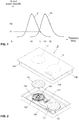
- FIG. 1 is a graph showing curves of resonance characteristics of two working coils respectively when an induction heating apparatus including the two working coils is driven.
- FIG. 1 shows a curve of a resonance characteristic of each of the working coils i.e., a curve 31 of a resonance characteristic of a first working coil and a curve 32 of a resonance characteristic of a second working coil, when the two working coils are respectively driven in a state in which a container is placed in each of the heating zones of the induction heating apparatus.
- a resonance frequency of the first working coil is fr1
- a resonance frequency of the second working coil is fr2.
- a first required power value of the first working coil is PI
- a required power value of the second working coil is P2. Accordingly, the first working coil is driven at a first driving frequency f1 corresponding to the first required power value P1, and the second working coil is driven at a second driving frequency f2 corresponding to the second required power value P2.
- interference noise is generated due to the driving of the working coils when a difference value f2-f1 between the driving frequencies of the working coils is included in an audible frequency band (e.g., 2 kHz to 20 kHz).
- the interference noise may cause inconvenience to a user and cause a user to wonder if the induction heating apparatus is out of order.
- a driving frequency of at least one of the two working coils is randomly adjusted such that the difference value f2-f1 between the driving frequencies of the working coils is out of the audible frequency band.
- the driving frequency of the working coil is randomly adjusted to reduce the interference noise, an output power value of the working coil does not match a required power value set by a user.
- An object of the present invention is to provide an induction heating apparatus and a method for controlling the same that may prevent interference noise caused by driving of two working coils while maintaining output power values and required power values of the working coils at the same value when the working coils are driven at the same time.
- An object of the present invention is to provide an induction heating apparatus and a method for controlling the same that may prevent interference noise caused by driving of working coils when various types of containers having different properties are heated.
- An induction heating apparatus may include a first working coil and a second working coil.
- the first working coil may be driven at a first driving frequency corresponding to a first required power value set by a user
- the second working coil may be driven at a second driving frequency corresponding to a second required power value set by the user.
- a controller may determine a third driving frequency corresponding to the third required power value.
- the driving frequency of the second working coil needs to be changed to the third driving frequency.
- the controller may calculate a difference value between the driving frequency of the working coil (e.g., the first working coil), the required power value of which is not changed, and the third driving frequency, and may compare the calculated difference value with a predetermined first reference range (e.g., a range from 5 kHz to 20 kHz).
- a predetermined first reference range e.g., a range from 5 kHz to 20 kHz.
- the controller may change an operation mode of a first inverter circuit from a full bridge mode to a frequency doubler mode.
- a resonance frequency of the first working coil may be changed, e.g. amplified to a twice a resonance frequency of the first working coil in the full bridge mode.
- the difference value between the driving frequency of the first working coil and the driving frequency of the second working coil may be greater than a boundary value (e.g., 20 kHz) of an audible frequency band.
- a boundary value e.g. 20 kHz
- An induction heating apparatus may include a first working coil, a first inverter circuit driven at a first driving frequency corresponding to a first required power value of the first working coil and configured to supply the first working coil with current, a second working coil, a second inverter circuit driven at a second driving frequency corresponding to a second required power value of the second working coil and configured to supply the second working coil with current, and a controller configured to determine a third driving frequency corresponding to a third required power value when the required power value of the first working coil or the second working coil is changed to the third required power value, to calculate a difference value between the driving frequency of the working coil, the required power value of which is not changed, and the third driving frequency, to change an operation mode of the first inverter circuit when the difference value is included in a predetermined first reference range, and to change an output power value of the working coil, the required power value of which is changed, to the third required power value.
- the controller may change the operation mode of the first inverter circuit to a frequency doubler mode.
- the first inverter circuit may include a variable capacitor part and a relay part connected to the variable capacitor part.
- the controller may set a capacitance value of the variable capacitor part to Cr,d of an equation below (equation 1) by opening or closing a plurality of relays included in the relay part.
- C r . d 1 2 ⁇ f r . d 2 L r
- fr,d may be a twice a frequency of a switching signal input to the first inverter circuit
- Lr may be an inductance value of a second inductor included in the first inverter circuit
- a resonance frequency of the first working coil may be amplified.
- the difference value between the driving frequency of the working coil, the required power value of which is not changed, and the third driving frequency may be a noise avoidance value or greater in an entire power range of the first working coil and an entire power range of the second working coil.
- the first inverter circuit may be a full bridge circuit.
- the second inverter circuit may be a half bridge circuit or a full bridge circuit.
- the controller may change a power control mode of the first working coil to an asymmetric pulse width modulation mode.
- a method for controlling an induction heating apparatus may include driving a first working coil at a first driving frequency corresponding to a first required power value, driving a second working coil at a second driving frequency corresponding to a second required power value, determining a third driving frequency corresponding to a third required power value when the required power value of the first working coil or the second working coil is changed to the third required power value, calculating a difference value between the driving frequency of the working coil, the required power value of which is not changed, and the third driving frequency, changing an operation mode a first inverter circuit configured to supply the first working coil with current when the difference value is included in a predetermined first reference range, and changing an output power value of the working coil, the required power value of which is changed, to the third required power value.
- changing an operation mode a first inverter circuit may include changing the operation mode of the first inverter circuit to a frequency doubler mode when the difference value is included in the predetermined first reference range.
- the first inverter circuit may include a variable capacitor part and a relay part connected to the variable capacitor part, wherein when the operation mode of the first inverter circuit is changed to the frequency doubler mode, a capacitance value of the variable capacitor part may be set to Cr,d of an equation below (equation 1) as a result of opening or closing of a plurality of relays included in the relay part.
- C r . d 1 2 ⁇ f r . d 2 L r
- fr,d may be a twice a frequency of a switching signal input to the first inverter circuit
- Lr may be an inductance value of a second inductor included in the first inverter circuit
- a resonance frequency of the first working coil may be amplified.
- the difference value between the driving frequency of the working coil, the required power value of which is not changed, and the third driving frequency may be a noise avoidance value or greater in an entire power range of the first working coil and an entire power range of the second working coil.
- the first inverter circuit may be a full bridge circuit
- the second inverter circuit configured to supply the second working coil with current may be a half bridge circuit or a full bridge circuit.
- the method for controlling an induction heating apparatus may further include changing a power control mode of the first working coil to an asymmetric pulse width modulation mode when the required power value of the first working coil is changed after the change in the operation mode of the first inverter circuit.
- the controller is checking whether the change of operation in any one of the working coils is causing any noise due to interference of the driving frequencies used for driving the two working coils, one of which is changed in its power and the other not.
- the third required power will be applied.
- the control or driving of the working coil being not changed in its required power is changed to a different mode to thereby drive the working coil being not changed in its required power with a driving frequency not causing any interference or noise.
- An induction heating apparatus may prevent interference noise caused by driving of two working coils while maintaining output power values and required power values of the working coils at the same value when the working coils are driven at the same time.
- the induction heating apparatus may prevent interference noise caused by driving of working coils when various types of containers having different properties are heated.
- FIG. 2 is an exploded perspective view showing an induction heating apparatus according to one embodiment.
- the induction heating apparatus 10 may include a case 102 constituting a main body, and a cover plate 104 coupled to the case 102 and configured to seal the case 102.
- the cover plate 104 may be coupled to an upper surface of the case 102 and may seal a space, formed in the case 102, from the outside.
- the cover plate 104 may include an upper plate 106 on which a container for cooking food is placed.
- the upper plate 106 may be made of tempered glass such as ceramic glass, but a material of the upper plate 106 may vary depending on embodiments.
- Heating zones 12, 14 respectively corresponding to working coil assemblies 122, 124 may be formed on the upper plate 106.
- lines or figures corresponding to the heating zones 12, 14 may be printed or displayed on the upper plate 106.
- the case 102 may have a hexahedron shape an upper portion of which is open.
- the working coil assemblies 122, 124 for heating a container may be arranged in the space formed in the case 102.
- an interface 114 may be arranged in the case 102, may allow a user to supply power or to adjust a power level of each heating zone 12, 14, and may display information in relation to the induction heating apparatus 10.
- the interface 114 may be implemented as a touch panel that makes it possible to input information and to display information as a result of a touch. However, an interface 114 having a different structure may be used depending on embodiments.
- the upper plate 106 may have a manipulation zone 118 at a position corresponding to a position of the interface 114.
- a manipulation zone 118 For a user's manipulation, letters or images and the like may be previously printed in the manipulation zone 118. The user may perform manipulation desired by the user by touching a specific point of the manipulation zone 118 with reference to the letters or images previously printed in the manipulation zone 118.
- Information output by the interface 114 may be displayed though the manipulation zone 118.
- the user may set a power level of each heating zone 12, 14 through the interface 114.
- the power level may be displayed on the manipulation zone 118 as numbers (e.g., 1, 2, 3,..., 9).
- a required power value and a driving frequency of a working coil corresponding to each heating zone 12, 14 may be determined.
- a controller may drive each working coil such that an output power value of each working coil matches the required power value set by the user, based on the determined driving frequency.
- a power supply 112 for supplying power to the working coil assembly 122, 124 or the interface 114 may be disposed in the space formed in the case 102.
- FIG. 2 shows two working coil assemblies, i.e., a first working coil assembly 122 and a second working coil assembly 124 arranged in the case 102 as an example. However, three or more working coil assemblies may be disposed in the case 102 depending on embodiments.
- the working coil assembly 122, 124 may include a working coil 132, 142 that forms an induction magnetic field using high-frequency alternating current supplied by the power supply 112, and a thermal insulation sheet that protects a coil from heat generated by a container.
- the first working coil assembly 122 may include a first working coil 132 for heating a container placed in a first heating zone 12, and a first thermal insulation sheet 130 in FIG. 2 .
- the second working coil assembly 124 may include a second working coil 142 and a second thermal insulation sheet. Depending on embodiments, the thermal insulation sheet may not be provided.
- a temperature sensor 134 may be disposed in a central portion of the one or more working coils 132, 142.
- a temperature sensor 134 may be in a central portion of the first working coil 132 in FIG. 2 .
- the temperature sensor 132 may measure a temperature of a container in each heating zone 12, 14.
- the temperature sensor 134 may be a thermistor temperature sensor having a variable resistance whose resistance value changes according to the temperature of the container, but is not limited thereto.
- the temperature sensor 134 may output sensing voltage corresponding to a temperature of a container, and the sensing voltage output from the temperature sensor 134 may be delivered to the controller 2.
- the controller 2 may check the temperature of the container based on magnitude of the sensing voltage output from the temperature sensor 134, and when the temperature of the container is a predetermined reference value or greater, the controller 2 may perform an overheat prevention function by lowering an output power value of a working coil 132, 142 or by stopping driving of a working coil 132, 142.
- a substrate on which a plurality of circuits or a plurality of elements including the controller 2 are mounted, may be disposed in the space formed in the case 102.
- the controller 2 may perform a heating operation by driving each working coil 132, 142 according to the user's heating initiation instruction input through the interface 114.
- the controller 2 may finish the heating operation by stopping the driving of the working coil 132, 142.
- FIG. 3 is a circuit diagram of an induction heating apparatus according to one embodiment.
- the induction heating apparatus 10 may include a first rectifier circuit 202, a first smoothing circuit L1, C1, a first inverter circuit 204, a first working coil 132, a second rectifier circuit 212, a second smoothing circuit L3, C5, a second inverter circuit 214, a second working coil 142, a first driving circuit 22, a second driving circuit 24, and a controller 2.
- the first rectifier circuit 202 may include a plurality of diode elements D1, D2, D3, D4.
- the first rectifier circuit 202 as illustrated in FIG. 3 , may be a bridge diode circuit, and may be a different circuit depending on embodiments.
- the first rectifier circuit 202 may rectify AC input voltage supplied from a power supply device 20 to output voltage having a pulse waveform.
- the first smoothing circuit L1, C1 may smooth the voltage rectified by the first rectifier circuit 202 and output DC link voltage.
- the first smoothing circuit L1, C1 may include a first inductor L1 and a first DC link capacitor C1.
- the first inverter circuit 204 may include a first switching element SW1, a second switching element SW2, a third switching element SW3, a fourth switching element SW4, a second inductor L2, a variable capacitor C2, C3, C4 including a plurality of capacitors, and a relay part 206.
- the first inverter circuit 204 of the induction heating apparatus 10 may be implemented as a full bridge circuit including the four switching elements SW1, SW2, SW3, SW4.
- the first switching element SW1, the second switching element SW2, the third switching element SW3, and the fourth switching element SW4 may be turned on and turned off by a first switching signal S1, a second switching signal S2, a third switching signal S3, and a fourth switching signal S4 respectively output from the first driving circuit 22.
- Each of the switching elements SW1, SW2, SW3, SW4 may be turned on when each of the switching signals S1, S2, S3, S4 is at a high level, and may be turned off when each of the switching signals S1, S2, S3, S4 is at a low level.
- any switching elements among the switching elements SW1, SW2, SW3, SW4 may be turned on and turned off complementarily.
- the second switching element SW2 may be turned off (turned on) while the first switching element SW1 is turned on (turned off).
- the switching elements that are turned on and turned off complementarily are referred to as "mutually complementary" switching elements.
- any switching elements among the switching elements SW1, SW2, SW3, SW4 may be turned on and turned off identically.
- the first switching element SW1 and the third switching element SW3 may be turned on and turned off at the same timing.
- the switching elements that are turned on and turned off at the same timing are referred to as "mutually corresponding" switching elements.
- DC link voltage input to the first inverter circuit 204 may be converted into AC voltage (AC current) as a result of turn-on and turn-off operations, i.e., switching operations, of the switching elements SW1, SW2, SW3, SW4 included in the first inverter circuit 204.
- the AC voltage (AC current) converted by the first inverter circuit 204 may be supplied to the second inductor L2, the first working coil 132 and the plurality of variable capacitors C2, C3, C4.
- resonance may occur in the first working coil 132, and thermal energy may be supplied to a container.
- the first switching signal S1, the second switching signal S2, the third switching signal S3 and the fourth switching signal S4 may be pulse width modulation (PWM) signals that respectively have a predetermined duty ratio.
- PWM pulse width modulation
- the relay part 206 may include a plurality of relays connected in series with each of the variable capacitors C2, C3, C4. Each relay included in the relay part 206 may be opened or closed by a control signal of the controller 2.
- an entire capacitance value of the variable capacitor C2, C3, C4 may vary. That is, the controller 2 may adjust a capacitance value of the variable capacitor part C2, C3, C4 by opening or closing the relays included in the relay part 206.
- the controller 2 may determine an operation mode of the first inverter circuit 204, and may control open/close state of each of the relays included in the relay part 206 such that the capacitance value of the variable capacitor part C2, C3, C4 corresponds to the operation mode of the first inverter circuit 204. As described below, a frequency of resonance current following in the working coil 132 may be adjusted based on the capacitance value of the variable capacitor part C2, C3, C4.
- variable capacitor part may include three capacitors C2, C3, C4 connected in parallel.
- the number of the capacitors included in the variable capacitor part may vary depending on embodiments.
- a connection (in series and/or in parallel) of the capacitor included in the variable capacitor part may differ depending on embodiments.
- the second rectifier circuit 212 may include a plurality of diode elements D5, D6, D7, D8.
- the second rectifier circuit 212 as illustrated in FIG. 3 , may be a bridge diode circuit, and may be a different circuit depending on embodiments.
- the second rectifier circuit 212 may rectify AC input voltage supplied from a power supply device 20 to output voltage having a pulse waveform.
- the second smoothing circuit L3, C5 may smooth the voltage rectified by the second rectifier circuit 212 and output DC link voltage.
- the second smoothing circuit L3, C5 may include a third inductor L3 and a second DC link capacitor C5.
- the second inverter circuit 214 may include a sixth capacitor C6, a seventh capacitor C7, a fifth switching element SW5, and a sixth switching element SW6. As illustrated in FIG. 3 , the second inverter circuit 214 of the induction heating apparatus 10 according to one embodiment may be implemented as a full bridge circuit including the two switching elements SW5, SW6. However, in another embodiment, the second inverter circuit 214, like the first inverter circuit 204, may also be implemented as a full bridge circuit including four switching elements.
- the fifth switching element SW5 and the sixth switching element SW6 may be complementarily turned on and turned off by a fifth switching signal S5 and a sixth switching signal S6 respectively output from the second driving circuit 24.
- FIG. 3 shows an IGBT element as each of the switching elements SW1, SW2, SW3, SW4, SW5, SW6.
- each of the switching elements SW1, SW2, SW3, SW4, SW5, SW6 may be a different type of switching element (e.g., a BJT or FET element and the like) depending on embodiments.
- DC link voltage input to the second inverter circuit 214 may be converted into AC voltage (AC current).
- the AC voltage (AC current) converted by the second inverter circuit 214 may be supplied to the second working coil 142.
- resonance may occur in the second working coil 142 and thermal energy may be supplied to a container.
- each of the fifth switching signal S5 and the sixth switching signal S6 may be a PWM signal having a predetermined duty ratio.
- each of the working coils 132, 142 When AC current output from each of the inverter circuits 204, 214 is supplied to each of the working coils 132, 142, each of the working coils 132, 142 may be driven. As a result of driving of each of the working coils 132, 142, eddy current may flow in the container placed over each of the working coil 132, 142 and the container may be heated. Magnitude of thermal energy supplied to the container may differ depending on magnitude of power that is actually generated as a result of driving of each of the working coils 132, 142, i.e., depending on an output power value of each of the working coils 132, 142.
- the controller 2 may determine a driving frequency of each of the working coils 132, 142 such that the driving frequency corresponds to a power level of a heating zone set by the user.
- the controller 2 may determine a driving frequency of each of the working coils 132, 142 with reference to a table in which a driving frequency corresponding to each power level is listed or with reference to an equation of a relationship between each power level and a driving frequency.
- magnitude of power, i.e., a required power value, output by each of the working coils 132, 142 may be determined based on the power level set by the user.
- the controller 2 may supply each of the driving circuits 22, 44 with a control signal corresponding to the determined driving frequency.
- Each of the driving circuits 22, 44 may output switching signals S1, S2, S3, S4, S5, S6 having a duty ratio corresponding to the driving frequency determined by the controller 2, based on the control signal output from the controller 2.
- the induction heating apparatus 10 When the induction heating apparatus 10 is powered on as a result of the user's manipulation of the interface 114 of the induction heating apparatus 10, the induction heating apparatus 10 may get into a driving standby state as power is supplied to the induction heating apparatus from the power supply device 20. Then the user may place a container over each of the working coils 132, 142 of the induction heating apparatus 10 and set a power level for the container to input an instruction for initiating a heating process to each of the working coils 132, 142. When the user inputs the heating initiation instruction, a power value required by each of the working coils 132, 142, i.e., a required power value may be determined depending on the power level set by the user.
- the controller 2 may determine a driving frequency corresponding to the required power value of each of the working coils 132, 142, and may supply a control signal corresponding to the determined driving frequency to each of the driving circuits 22, 24. Accordingly, each of the driving circuits 22, 24 may output switching signals S1, S2, S3, S4, S5, S6, and each of the working coils 132, 142 may be driven as the switching signals S1, S2, S3, S4, S5, S6 are respectively input to the switching elements SW1, SW2, SW3, SW4, SW5, SW6. As a result of driving of each of the working coils 132, 142, eddy current may flow in the container, and the container may be heated.
- the required power value of the first working coil 132 or the second working coil 142 may be changed to a third required power value by the user.
- the controller 2 needs to change the driving frequency of the first working coil 132 to a third driving frequency corresponding to the third required power value (e.g., 500 W).
- interference noise may be generated depending on a difference value between the driving frequency of the working coil, whose driving frequency is not changed, and the third driving frequency.
- the controller 2 may determine the third driving frequency corresponding to the third required power value when the required power value of the first working coil 132 or the second working coil 142 is changed to the third required power value.
- the controller 2 may calculate a difference value between the driving frequency of the working coil the required power value of which is not changed, and the third driving frequency.
- a difference value between two driving frequencies denotes a value that is calculated as a result of deduction of a small value from a large value out of the two driving frequencies.
- the controller 2 may change an operation mode of the first inverter circuit 204 when the calculated difference value is included within a predetermined first reference range (e.g., a range from 5 kHz to 20 kHz).
- a predetermined first reference range e.g., a range from 5 kHz to 20 kHz.
- the operation mode of the first inverter circuit 204 may be changed from a full bridge mode to a frequency doubler mode.
- a resonance frequency of the first working coil 132 may be amplified by two times.
- the difference value between the driving frequency of the working coil, the required power value of which is not changed, and the third driving frequency may be a predetermined noise avoidance value or greater.
- the noise avoidance value may be set to a value (e.g., 22 kHz) greater than a maximum value (e.g., 20 kHz) among boundary values of an audible frequency band, and may be set differently depending on embodiments.
- the controller 2 may change an output power value of the working coil, the required power value of which is changed, to the third required power value. As a result of control above, interference noise caused by the driving of the first working coil 132 and the second working coil 142 may be prevented.
- the controller 2 may set the driving frequency of the first working coil 132 and the driving frequency of the second working coil 142 to the same value. As a result of control above, generation of interference noise, caused by the driving of the first working coil 132 and the second working coil 142, may be prevented.
- the controller 2 may set the driving frequency of the working coil, the required power value of which is changed, to the third driving frequency and may not change the driving frequency of the working coil, the required power value of which is not changed.
- interference noise when the difference value between the driving frequency of the working coil, the required power value of which is not changed, and the third driving frequency is not included in the first reference range and the second reference range, interference noise may be prevented.
- boundary values of the first reference range and the second reference range may be set differently depending on embodiments.
- FIG. 4 shows waveforms of switching signals, input voltage and resonance current when an operation mode of a first inverter circuit is a full bridge mode, respectively, in one embodiment.
- the controller 2 may supply a control signal to the driving circuit 22 such that the driving circuit 22 outputs switching signals S1, S2, S3, S4 having waveforms illustrated in FIG. 4 .
- the controller 2 may set a capacitance value of the variable capacitor part C1, C2, C3 to Cr,f as in the following equation (equation 1) such that resonance current supplied to the first working coil 132 is output once during a first cycle TS1 of the switching signal S1, S2, S3, S4, in other words, such that a frequency of resonance current supplied to the first working coil 132 becomes a same value as a frequency of the switching signal S1, S2, S3, S4.
- C r . f 1 2 ⁇ f r . f 2 L r
- Equation 1 fr,f is the same as the frequency of the switching signal S1, S2, S3, S4, and Lr denotes an inductance value of the second inductor L2.
- the controller 2 may open or close each of the relays included in the relay part 206 such that an entire capacitance value of the variable capacitor part C1, C2, C3 matches the capacitance value Cr,f in equation 1.
- the controller 2 may supply the first inverter circuit 204 with switching signals S1, S2, S3, S4 having waveforms illustrated in FIG. 4 through the first driving circuit 22. As a result, a process of heating the container may be performed.
- each of the switching signals may have a turn-on section and a turn-off section within the first cycle TS1.
- time in the turn-on section is referred to as turn-on time TS11
- time in the turn-off section is referred to as turn-off time TS12.
- a ratio of the turn-on time TS11 to the first cycle TS1 is referred to as a duty ratio of the switching signal. For example, under the assumption that the first cycle TS1 of the first switching signal S1 is one second and that the turn-on time TS11 is 0.5 second, the duty ratio of the first switching signal S1 is 50 % (or 0.5).
- the first switching element SW1 and the second switching element SW2 may be complementarily turned-on and turned-off.
- the third switching element SW3 and the fourth switching element SW4 may be complementarily turned-on and turned-off.
- FIG. 4 shows a waveform of Vab that is magnitude of voltage between a node and b node in the circuit diagram of FIG. 4 .
- Vab is the same as an input voltage value Vin that is magnitude of input voltage input to the first working coil 132.
- FIG. 4 also shows a waveform of input current, i.e., resonance current, input to the first working coil 132
- the input voltage Vab and the resonance current have the same frequency. Additionally, the frequencies of the input voltage Vab and the resonance current are the same as the frequency of the switching signal S1, S2, S3, S4. Accordingly, a voltage gain of the first working coil 132 may be maintained at a maximum value (e.g., 1), and power may be supplied to the container reliably.
- a maximum value e.g. 1, 1
- FIG. 5 shows waveforms of switching signals, input voltage, and resonance current when an operation mode of a first inverter circuit is a frequency doubler mode, respectively, in one embodiment.
- the controller 2 may supply a control signal to the first driving circuit 22 such that the first driving circuit 22 outputs switching signals S1, S2, S3, S4 having waveforms illustrated in FIG. 5 .
- the controller 2 may set a capacitance value of the variable capacitor part C1, C2, C3 to Cr,d as in the following equation (equation 2) such that resonance current supplied to the first working coil 132 is output twice during a first cycle TS2 of the switching signal S1, S2, S3, S4, in other words, such that a frequency of resonance current supplied to the first working coil 132 becomes twice a frequency of the switching signal S1, S2, S3, S4.
- Equation 2 1 2 ⁇ f r . d 2 L r
- fr,d denotes a twice the frequency of the switching signal S1, S2, S3, S4, and Lr denotes an inductance value of the second inductor L2.
- the controller 2 may open or close each of the relays included in the relay part 206 such that an entire capacitance value of the variable capacitor part C1, C2, C3 matches the capacitance value Cr,d in equation 2.
- the controller 2 may supply the first inverter circuit 204 with switching signals S1, S2, S3, S4 having waveforms illustrated in FIG. 5 through the first driving circuit 22. As a result, a process of heating the container may be performed.
- the first switching element SW1 and the third switching element SW3 may be complementarily turned-on and turned-off.
- the second switching element SW2 and the fourth switching element SW4 may be complementarily turned on and turned off.
- FIG. 5 shows a waveform of Vab that is magnitude of voltage between a node and b node in the circuit diagram of FIG. 4 .
- Vab is the same as an input voltage value Vin that is magnitude of input voltage input to the first working coil 132.
- FIG. 5 also shows a waveform of input current, i.e., resonance current, input to the first working coil 132.
- the input voltage Vab and the resonance current have the same frequency. Additionally, the frequencies of the input voltage Vab and the resonance current are a twice the frequency of the switching signal S1, S2, S3, S4. Accordingly, a voltage gain of the first working coil 132 may be maintained at a maximum value (e.g., 1), and power may be supplied to the container reliably. Although the resonance frequency band and the driving frequency band of the first working coil 132 are increased, a voltage gain of the first working coil 132 may be maintained at a maximum value (e.g., 1). Thus, when a container such as a non-magnetic container having low power conversion efficiency is used, an input current value Iin of the first working coil 132 may not increase and power may be supplied to the container reliably.
- the controller 2 may determine the power control mode of the first inverter circuit 204 as an asymmetric pulse width modulation mode. In the asymmetric pulse width modulation mode, the controller 2 may adjust the duty ratio of the switching signal S1, S2, S3, S4 while maintaining the frequency of the switching signal S1, S2, S3, S4 to adjust an output power value of the first working coil 132.
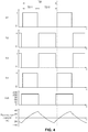
- FIG. 6 shows waveforms of switching signals, input voltage, and resonance current when an operation mode of a first inverter circuit is a frequency doubler mode and a power control mode of the first inverter circuit is an asymmetric pulse width modulation mode, respectively, in one embodiment.
- the controller 2 may adjust the duty ratio of the switching signal S1, S2, S3, S4 to adjust the output power value of the first working coil 132.
- magnitude Vab of input voltage and magnitude of resonance current may respectively change depending on turn-on time TS11 of the first switching signal S1 and the third switching signal S3 (or turn-off time of the second switching signal S2 and the fourth switching signal S4), and turn-on time TS12 of the second switching signal S2 and the fourth switching signal S4 (or turn-off time of the first switching signal S1 and the third switching signal S3).
- the controller 2 may adjust the output power value of the first working coil 132 by adjusting the turn-on time TS11 of the first switching signal S1 and the third switching signal S3, i.e., the duty ratio of the first switching signal S1 and the third switching signal S3.
- the controller 2 may increase the output power value of the first working coil 132 by increasing the turn-on time TS11 of the first switching signal S1 and the third switching signal S3, in other words, by increasing the duty ratio of the first switching signal S1 and the third switching signal S3.
- the controller 2 may decrease the output power value of the first working coil 132 by decreasing the turn-on time TS11 of the first switching signal S1 and the third switching signal S3, in other words, by decreasing the duty ratio of the first switching signal S1 and the third switching signal S3.
- FIG. 7 is a graph showing a curve of a resonance characteristic of a working coil when an operation mode of a first inverter circuit is a frequency doubler mode, in one embodiment.
- FIG. 7 shows a curve 51 of a resonance characteristic of the first working coil 132 in the full bridge operation mode of the first inverter circuit 204, and a curve 52 of a resonance characteristic of the first working coil 132 in the frequency doubler mode of the first inverter circuit 204, respectively.
- a frequency of resonance current of the first working coil 132 may be set to a twice the frequency of the switching signal S1, S2, S3, S4. Accordingly, the resonance frequency of the first working coil 132 may be changed to 2 ⁇ fr that is a two times of fr, as in FIG. 7 .
- a driving frequency of the first working coil 132 with respect to the same output power value may also become higher.
- the driving frequency of the first working coil 132 needs to be set to f1 such that the first working coil 132 outputs power of P1.
- the driving frequency of the first working coil 132 needs to be set to 2 ⁇ f1 that is a twice f1 such that the first working coil 132 outputs the power of P1.
- the driving frequency of the first working coil 132 may not be 2 ⁇ f1.
- the driving frequency band of the first working coil 132 in the frequency doubler mode may be greater than in the full bridge mode.
- the frequency of the input voltage and the frequency of the resonance current may be maintained at the same level, and the voltage gain may be set to a maximum value. Accordingly, although the driving frequency of the first working coil 132 is not set to a high frequency, the output power value of the first working coil 132 may be maintained at a high level.
- FIG. 7 shows a curve 52 of a resonance characteristic of the first working coil 132 at a 50 % duty ratio of the first switching signal S1 and the third switching signal S3 in the frequency doubler mode, and a curve 53 of a resonance characteristic of the first working coil 132 at a 30 % duty ratio of the first switching signal S1 and the third switching signal S3 in the frequency doubler mode, respectively.
- the output power value of the first working coil 132 may be P1.
- the controller 2 reduces the duty ratios of the first switching signal S1 and the third switching signals S3 from 50 % to 30 % while maintaining the driving frequency of the first working coil 132, the output power value of the first working coil 132 may be reduced to P2.
- the controller 2 may adjust the output power value of the first working coil 132 only by adjusting the duty ratios of the first switching signal S1 and the third switching signals S3 according to the asymmetric pulse width modulation method while maintaining the driving frequency of the first working coil 132 at the same value (e.g., 2 ⁇ f1) in the frequency doubler mode.
- FIG. 8 is a graph showing power conversion efficiency of an induction heating apparatus when a power control mode of a first inverter circuit is set to a pulse frequency modulation mode and an asymmetric pulse width modulation mode in a state in which an operation mode of the first inverter circuit is a frequency doubler mode, respectively, in one embodiment.
- FIG. 8 shows a graph 54 of power conversion efficiency with respect to each input power value when the power control mode of the first inverter circuit 204 is the pulse frequency modulation mode, that is, when the controller 2 adjusts the driving frequency of the first working coil 132 to adjust the output power value of the first working coil 132, in the state in which the operation mode of the first inverter circuit 204 is the frequency doubler mode.
- FIG. 8 also shows a graph 55 of power conversion efficiency with respect to each input power value when the power control mode of the first inverter circuit 204 is the asymmetric pulse width modulation mode, that is, when the controller 2 adjusts the duty ratio of the switching signal without changing the driving frequency of the first working coil 132 to adjust the output power value of the first working coil 132, in the state in which the operation mode of the first inverter circuit 204 is the frequency doubler mode.
- the power conversion efficiency denotes a ratio of power actually delivered to a container to power input to the first working coil 132. For example, when the input power of the first working coil 132 is 1000 W and the power conversion efficiency is 80 %, 800 W of power may be actually delivered to a container.
- the power conversion efficiency in the power control mode of the first inverter circuit 204 set to the asymmetric pulse width modulation mode is greater than in the power control mode of the first inverter circuit 204 set to the pulse frequency modulation mode. Accordingly, the power conversion efficiency of the working coil 132 of the induction heating apparatus according to the disclosure is increased compared to a working coil of an induction heating apparatus of the related art, by adjusting the output power value of the first working coil 132 using the asymmetric pulse width modulation method in the state in which the operation mode of the first inverter circuit 204 is set to the half bridge mode.
- the controller 2 may change the power control mode of the first working coil 132 to the asymmetric pulse width modulation mode.
- the induction heating apparatus 10 may set the operation mode of the first inverter circuit 204 as the full bridge mode or the frequency doubler mode to heat a container, thereby making it possible to heat containers having different properties without generating interference noise.
- FIG. 9 is a graph showing a curve of a resonance characteristic of a first working coil and a second working coil when a required power value of the second working coil changes in a state in which a resonance frequency of the first working coil and a resonance frequency of the second working coil differ from each other, respectively, in one embodiment.
- FIG. 10 is a graph showing a curve of a resonance characteristic of each of the first working coil and the second working coil when an operation mode of the first working coil is changed to a frequency doubler mode to prevent interference noise, in the embodiment of FIG. 9 .
- a user may place a container in a first heating zone 12 and input a heating initiation instruction.
- a first required power value of the first working coil 132 corresponding to a power level of the first heating zone 12 set by the user, may be PI, and a driving frequency corresponding to the first required power value PI may be 37 kHz.
- a controller 2 may set an operation mode of a first inverter circuit 204 to a full bridge mode, set a first driving frequency of the first working coil 132 to 37 kHz and supply a control signal to a first driving circuit 22.
- the first working coil 132 may show the same resonance characteristic as that of the curve 61.
- the first working coil 132 may be driven at the driving frequency of 37 kHz, and an output power value of the first working coil 132 may be P1. In this case, a resonance frequency of the first working coil 132 may be 35 kH.
- a second required power value of the second working coil 142 corresponding to a power level of the second heating zone 14 set by the user, may be P2, and a driving frequency corresponding to the second required power value P2 may be 16 kHz.
- the controller 2 may set a second driving frequency of the second working coil 142 to 16 kHz and supply a control signal to a second driving circuit 24.
- the second working coil 142 may show the same resonance characteristic as that of the curve 62.
- the second working coil 142 may be driven at the driving frequency of 16 kHz, and an output power value of the second working coil 142 may be P2. In this case, a resonance frequency of the second working coil 142 may be 14 kHz.
- the user may decrease the power level of the second heating zone 14. As the power level of the second heating zone 14 decreases, the required power value of the second working coil 142 may decrease from P2 to P3.
- the controller 2 may determine a third driving frequency corresponding to a third required power value P3 that is a new required power value of the working coil, i.e., the second working coil 142 the required power value of which is changed. As illustrated in FIG. 9 , the third frequency corresponding to the third required power value P3 may be determined as 19 kHz.
- the controller 2 may calculate a difference value between the third driving frequency of the working coil the required power value of which is changed, and the driving frequency (the first driving frequency) of the working coil (the first working coil 132) the required power value of which is not changed.
- the difference value between the third driving frequency (19 kHz) and the first driving frequency (37 kHz) may be 18.
- the controller 2 may confirm whether the calculated difference value (18) is included in a predetermined first reference range (e.g., a range from 5 kHz to 20 kHz). Since the calculated difference value (18) is included in the first reference range, the controller 2 may change the operation mode of the first inverter circuit 204 to the frequency doubler mode. Accordingly, switching signals S1, S2, S3, S4 having waveforms illustrated in FIG. 5 may be respectively input to the first inverter circuit 204.
- a predetermined first reference range e.g., a range from 5 kHz to 20 kHz.
- a resonance frequency of the first working coil 132 may become a twice an existing resonance frequency.
- the first working coil 132 may show a resonance characteristic that is new and the same as the resonance characteristic of the curve 63 illustrated in FIG. 10 , and the resonance frequency of the first working coil 132 may be changed to 70kHz.
- the first driving frequency corresponding to the first required power value P1 of the first working coil 132 may be changed to 73 kHz.
- the controller 2 may drive the first working coil 132 at the first driving frequency (73 kHz) and drive the second working coil 142 at the third driving frequency (19 kHz).
- interference noise caused by the driving of the first working coil 132 and the second working coil 142 may be prevented although the output power value of the second working coil 142 is changed from P2 to P3.
- the controller 2 may change a power control mode of the first inverter circuit 204 to an asymmetric pulse width modulation mode. That is, the controller 2 may change a duty ratio of the switching signal input to the first inverter circuit 204 without changing the driving frequency of the first working coil 132 to change the output power value of the first working coil1 132.
- the controller 2 may change the diving frequency of the first working coil 132 to change the output power value of the first working coil 132 even after the operation mode of the first inverter circuit 204 is changed to the frequency doubler mode and the required power value of the first working coil 132 is changed as illustrated in FIG. 10 .
- FIG. 11 is a graph showing a curve of a resonance characteristic of a first working coil and a second working coil when a required power value of the first working coil changes in a state in which a resonance frequency of the first working coil and a resonance frequency of the second working coil differ from each other, respectively, in another embodiment.
- FIG. 12 is a graph showing a curve of a resonance characteristic of each of the first working coil and the second working coil when an operation mode of the first working coil is changed to a frequency doubler mode to prevent interference noise, in the embodiment of FIG. 11 .
- a user may place a container in the first heating zone 12 and input a heating initiation instruction.
- a first required power value of the first working coil 132 corresponding to a power level of the first heating zone 12 set by the user, may be PI, and a driving frequency corresponding to the first required power value PI may be 41 kHz.
- the controller 2 may set an operation mode of the first inverter circuit 204 to the full bridge mode, set a first driving frequency of the first working coil 132 to 41 kHz and supply a control signal to the first driving circuit 22.
- the first working coil 132 may show the same resonance characteristic as that of the curve 64.
- the first working coil 132 may be driven at the driving frequency of 41 kHz, and an output power value of the first working coil 132 may be P1. In this case, a resonance frequency of the first working coil 132 may be 35 kHz.
- a second required power value of the second working coil 142 corresponding to a power level of the second heating zone 14 set by the user, may be P2, and a driving frequency corresponding to the second required power value P2 may be 19 kHz.
- the controller 2 may set a second driving frequency of the second working coil 142 to 19 kHz and supply a control signal to the second driving circuit 24.
- the second working coil 142 may show the same resonance characteristic as that of the curve 65.
- the second working coil 142 may be driven at the driving frequency of 19 kHz, and an output power value of the second working coil 142 may be P2. In this case, a resonance frequency of the second working coil 142 may be 14 kHz.
- the user may increase the power level of the first heating zone 12. As the power level of the first heating zone 12 increases, the required power value of the first working coil 132 may increase from P1 to P3.
- the controller 2 may determine a third driving frequency corresponding to a third required power value P3 that is a new required power value of the working coil, i.e., the first working coil 132 the required power value of which is changed. As illustrated in FIG. 11 , the third frequency corresponding to the third required power value P3 may be determined as 37 kHz.
- the controller 2 may calculate a difference value between the third driving frequency of the working coil the required power value of which is changed, and the driving frequency (the second driving frequency) of the working coil (the second working coil 142) the required power value of which is not changed.
- the difference value between the third driving frequency (37 kHz) and the second driving frequency (19 kHz) may be 18.
- the controller 2 may confirm whether the calculated difference value (18) is included in a predetermined first reference range (e.g., a range from 5 kHz to 20 kHz). Since the calculated difference value (18) is included in the first reference range, the controller 2 may change the operation mode of the first inverter circuit 204 to the frequency doubler mode. Accordingly, switching signals S1, S2, S3, S4 having waveforms illustrated in FIG. 5 may be respectively input to the first inverter circuit 204.
- a predetermined first reference range e.g., a range from 5 kHz to 20 kHz.
- a resonance frequency of the first working coil 132 may become a twice an existing resonance frequency.
- the first working coil 132 may show a resonance characteristic that is new and the same as the resonance characteristic of the curve 66 illustrated in FIG. 12 , and the resonance frequency of the first working coil 132 may be changed to 70 kHz.
- the third driving frequency corresponding to the third required power value P3 of the first working coil 132 may be changed to 73 kHz.
- the controller 2 may drive the first working coil 132 at the third driving frequency (73 kHz) and drive the second working coil 142 at the second driving frequency (19 kHz).
- interference noise caused by the driving of the first working coil 132 and the second working coil 142 may be prevented although the output power value of the first working coil 132 is changed from PI to P3.
- the controller 2 may change the power control mode of the first inverter circuit 204 to the asymmetric pulse width modulation mode.
- the controller 2 may change the diving frequency of the first working coil 132 to change the output power value of the first working coil 132 even after the operation mode of the first inverter circuit 204 is changed to the frequency doubler mode and the required power value of the first working coil 132 is changed as illustrated in FIG. 10 .
- FIG. 13 is a graph showing a curve of a resonance characteristic of a first working coil and a second working coil when a required power value of the first working coil changes in a state in which a resonance frequency of the first working coil and a resonance frequency of the second working coil are the same, respectively, in yet another embodiment.
- FIG. 14 is a graph showing a curve of a resonance characteristic of each of the first working coil and the second working coil when an operation mode of the first working coil is changed to a frequency doubler mode to prevent interference noise, in the embodiment of FIG. 13
- a user may place a container in the first heating zone 12 and input a heating initiation instruction.
- a first required power value of the first working coil 132 corresponding to a power level of the first heating zone 12 set by the user, may be PI, and a driving frequency corresponding to the first required power value PI may be 22 kHz.
- the controller 2 may set an operation mode of the first inverter circuit 204 to the full bridge mode, set a first driving frequency of the first working coil 132 to 22 kHz and supply a control signal to the first driving circuit 22.
- the first working coil 132 may show the same resonance characteristic as that of the curve 67.
- the first working coil 132 may be driven at the driving frequency of 22 kHz, and an output power value of the first working coil 132 may be P1. In this case, a resonance frequency of the first working coil 132 may be 20 kHz.
- a second required power value of the second working coil 142 corresponding to a power level of the second heating zone 14 set by the user, may be P2, and a driving frequency corresponding to the second required power value P2 may be 22 kHz.
- the controller 2 may set a second driving frequency of the second working coil 142 to 22 kHz and supply a control signal to the second driving circuit 24.
- the second working coil 142 may show the same resonance characteristic as that of the curve 68.
- the second working coil 142 may be driven at the driving frequency of 22 kHz, and an output power value of the second working coil 142 may be P2.
- a resonance frequency of the second working coil 142 may be 22 kHz. That is, in the embodiment of FIG. 13 , the resonance frequency of the first working coil 132 and the resonance frequency of the second working coil 142 may be the same.
- the user may decrease the power level of the first heating zone 12. As the power level of the first heating zone 12 decreases, the required power value of the first working coil 132 may decrease from PI to P3.
- the controller 2 may determine a third driving frequency corresponding to a third required power value P3 that is a new required power value of the working coil, i.e., the first working coil 132 the required power value of which is changed. As illustrated in FIG. 11 , the third frequency corresponding to the third required power value P3 may be determined as 30 kHz.
- the controller 2 may calculate a difference value between the third driving frequency of the working coil the required power value of which is changed, and the driving frequency (the second driving frequency) of the working coil (the second working coil 142) the required power value of which is not changed.
- the difference value between the third driving frequency (30 kHz) and the second driving frequency (22 kHz) may be 8.
- the controller 2 may confirm whether the calculated difference value (8) is included in a predetermined first reference range (e.g., a range from 5 kHz to 20 kHz). Since the calculated difference value (8) is included in the first reference range, the controller 2 may change the operation mode of the first inverter circuit 204 to the frequency doubler mode. Accordingly, switching signals S1, S2, S3, S4 having waveforms illustrated in FIG. 5 may be respectively input to the first inverter circuit 204.
- a predetermined first reference range e.g., a range from 5 kHz to 20 kHz.
- a resonance frequency of the first working coil 132 may become a twice an existing resonance frequency.
- the first working coil 132 may show a resonance characteristic that is new and the same as the resonance characteristic of the curve 69 illustrated in FIG. 14 , and the resonance frequency of the first working coil 132 may be changed to 40 kHz.
- the third driving frequency corresponding to the third required power value P3 of the first working coil 132 may be changed to 52 kHz.
- the controller 2 may drive the first working coil 132 at the third driving frequency (52 kHz) and drive the second working coil 142 at the second driving frequency (23 kHz).
- interference noise caused by the driving of the first working coil 132 and the second working coil 142 may be prevented although the output power value of the first working coil 132 is changed from PI to P3.
- the controller 2 may change the power control mode of the first inverter circuit 204 to the asymmetric pulse width modulation mode.
- the controller 2 may change the diving frequency of the first working coil 132 to change the output power value of the first working coil 132 even after the operation mode of the first inverter circuit 204 is changed to the frequency doubler mode and the required power value of the first working coil 132 is changed as illustrated in FIG. 10 .
- FIG. 15 is a flow chart showing a method for controlling an induction heating apparatus according to one embodiment.
- a controller 2 of the induction heating apparatus 10 may drive a first working coil 132 at a first driving frequency corresponding to a first required power value set by a user (702). Additionally, the controller 2 may drive a second working coil 142 at a second driving frequency corresponding to a second required power value set by the user (704).
- the controller 2 may determine a third driving frequency corresponding to the third required power value (706).
- the controller 2 may calculate a difference value between the driving frequency of the working coil, the required power value of which is not change, and the third driving frequency (708).
- the controller 2 may change an operation mode of a first inverter circuit 204 configured to supply the first working coil 132 with current when the calculated difference value is included in a predetermined first reference range (710).
- changing the operation mode the first inverter circuit 204 (710) may include changing the operation mode of the first inverter circuit 204 to a frequency doubler mode when the difference value calculated in step 708 is included in the first reference range.
- a resonance frequency of the first working coil 132 may be amplified. Additionally, when the operation mode of the first inverter circuit 204 is changed, the difference value between the driving frequency of the working coil, the required power value of which is not changed, and the third driving frequency may be a noise avoidance value or greater in an entire power range of the first working coil 132 and an entire power range of the second working coil 142.
- the controller 2 may change may change an output power value of the working coil the required power value of which is changed to the third required power value (712).
- the difference value between the driving frequency of the working coil, the required power value of which is changed, and the driving frequency of the working coil, the required power value of which is not changed may be out of a second reference range, thereby preventing generation of interference noise.
- the method for controlling an induction heating apparatus may further include changing a power control mode of the first working coil 132 to an asymmetric pulse width modulation mode when the required power value of the first working coil 132 is changed after the change in the operation mode of the first inverter circuit 204.
Landscapes
- Physics & Mathematics (AREA)
- Electromagnetism (AREA)
- Engineering & Computer Science (AREA)
- Power Engineering (AREA)
- General Induction Heating (AREA)
- Induction Heating Cooking Devices (AREA)
- Control Of High-Frequency Heating Circuits (AREA)
Abstract
In one embodiment, when a user changes a required power value of a first working coil or a second working coil to a third required power value, a controller determines a third driving frequency corresponding to the third required power value. The controller according to one embodiment calculates a difference value between a driving frequency of the working coil, the required power value of which is not changed, and the third driving frequency, and compares the calculated difference value with a predetermined first reference range. When the calculated difference value is included in the first reference range, the controller changes an operation mode of a first inverter circuit from a full bridge mode to a frequency doubler mode, and changes an output power value of the working coil the required power value of which is changed to the third required power value.
Description
- This application claims priority to and the benefit of Korean Patent Application No.
10-2020-0054013, filed on May 6, 2020 - Disclosed herein are an induction heating apparatus and a method of controlling the same.
- Induction heating apparatuses are devices that generate eddy current in a metallic container and heat the container using a magnetic field generated around a working coil. When an induction heating apparatus is driven, high-frequency current is supplied to the working coil. Then, an induction magnetic field is generated around the working coil disposed in the induction heating apparatus. When magnetic line of force of the induction magnetic field passes through a bottom of the metallic container over the working coil, eddy current is generated inside the bottom of the container. Accordingly, the eddy current flows in the container, and the container itself is heated.
- The induction heating apparatus includes two or more heating zones and two or more working coils corresponding to the two or more heating zones. For example, when a user places containers respectively in two heating zones and inputs heating initiation instructions, each of the working coils is driven at a driving frequency corresponding to a required power value set by the user.
-
FIG. 1 is a graph showing curves of resonance characteristics of two working coils respectively when an induction heating apparatus including the two working coils is driven. -
FIG. 1 shows a curve of a resonance characteristic of each of the working coils i.e., acurve 31 of a resonance characteristic of a first working coil and acurve 32 of a resonance characteristic of a second working coil, when the two working coils are respectively driven in a state in which a container is placed in each of the heating zones of the induction heating apparatus. InFIG. 1 , a resonance frequency of the first working coil is fr1, and a resonance frequency of the second working coil is fr2. - In
FIG. 1 , a first required power value of the first working coil is PI, and a required power value of the second working coil is P2. Accordingly, the first working coil is driven at a first driving frequency f1 corresponding to the first required power value P1, and the second working coil is driven at a second driving frequency f2 corresponding to the second required power value P2. - When the two working coils are driven at the same time as illustrated in
FIG. 1 , interference noise is generated due to the driving of the working coils when a difference value f2-f1 between the driving frequencies of the working coils is included in an audible frequency band (e.g., 2 kHz to 20 kHz). The interference noise may cause inconvenience to a user and cause a user to wonder if the induction heating apparatus is out of order. - In the related art, a driving frequency of at least one of the two working coils is randomly adjusted such that the difference value f2-f1 between the driving frequencies of the working coils is out of the audible frequency band. However, when the driving frequency of the working coil is randomly adjusted to reduce the interference noise, an output power value of the working coil does not match a required power value set by a user.
- An object of the present invention is to provide an induction heating apparatus and a method for controlling the same that may prevent interference noise caused by driving of two working coils while maintaining output power values and required power values of the working coils at the same value when the working coils are driven at the same time.
- An object of the present invention is to provide an induction heating apparatus and a method for controlling the same that may prevent interference noise caused by driving of working coils when various types of containers having different properties are heated.
- Aspects according to the present disclosure are not limited to the above ones, and other aspects and advantages that are not mentioned above can be clearly understood from the following description and can be more clearly understood from the embodiments set forth herein. Additionally, the aspects and advantages in the present disclosure can be realized via means and combinations thereof that are described in the appended claims.
- The object is solved by the features of the independent claims. Preferred embodiments are given in the depending claims.
- An induction heating apparatus according to one embodiment may include a first working coil and a second working coil. The first working coil may be driven at a first driving frequency corresponding to a first required power value set by a user, and the second working coil may be driven at a second driving frequency corresponding to a second required power value set by the user.
- In one embodiment, when the user changes the required power value of the first working coil or the second working coil to a third required power value, a controller may determine a third driving frequency corresponding to the third required power value.
- For example, when the user changes the required power value of the second working coil to the third required power value, the driving frequency of the second working coil needs to be changed to the third driving frequency.
- However, when the second working coil is driven at the third driving frequency, interference noise may be caused by the first working coil and the second working coil. To prevent this from happening, the controller according to one embodiment may calculate a difference value between the driving frequency of the working coil (e.g., the first working coil), the required power value of which is not changed, and the third driving frequency, and may compare the calculated difference value with a predetermined first reference range (e.g., a range from 5 kHz to 20 kHz).
- When the calculated difference value is included in the first reference range, it means that interference noise is caused by the first working coil and the second working coil. To prevent the interference noise, the controller according to one embodiment may change an operation mode of a first inverter circuit from a full bridge mode to a frequency doubler mode.
- When the operation mode of the first inverter circuit is changed to the frequency doubler mode, a resonance frequency of the first working coil may be changed, e.g. amplified to a twice a resonance frequency of the first working coil in the full bridge mode.
- As the driving frequency of the first working coil becomes higher, the difference value between the driving frequency of the first working coil and the driving frequency of the second working coil may be greater than a boundary value (e.g., 20 kHz) of an audible frequency band. As a result of control above, the interference noise caused by the driving of the two working coils may be prevented.
- An induction heating apparatus according to one embodiment may include a first working coil, a first inverter circuit driven at a first driving frequency corresponding to a first required power value of the first working coil and configured to supply the first working coil with current, a second working coil, a second inverter circuit driven at a second driving frequency corresponding to a second required power value of the second working coil and configured to supply the second working coil with current, and a controller configured to determine a third driving frequency corresponding to a third required power value when the required power value of the first working coil or the second working coil is changed to the third required power value, to calculate a difference value between the driving frequency of the working coil, the required power value of which is not changed, and the third driving frequency, to change an operation mode of the first inverter circuit when the difference value is included in a predetermined first reference range, and to change an output power value of the working coil, the required power value of which is changed, to the third required power value.
- In one embodiment, when the difference value is included in the predetermined first reference range, the controller may change the operation mode of the first inverter circuit to a frequency doubler mode.
- In one embodiment, the first inverter circuit may include a variable capacitor part and a relay part connected to the variable capacitor part.
- Preferably, the controller may set a capacitance value of the variable capacitor part to Cr,d of an equation below (equation 1) by opening or closing a plurality of relays included in the relay part.

- Herein, fr,d may be a twice a frequency of a switching signal input to the first inverter circuit, and Lr may be an inductance value of a second inductor included in the first inverter circuit.
- In one embodiment, when the operation mode of the first inverter circuit is changed, a resonance frequency of the first working coil may be amplified.
- In one embodiment, when the operation mode of the first inverter circuit is changed, the difference value between the driving frequency of the working coil, the required power value of which is not changed, and the third driving frequency may be a noise avoidance value or greater in an entire power range of the first working coil and an entire power range of the second working coil.
- In one embodiment, the first inverter circuit may be a full bridge circuit.
- The second inverter circuit may be a half bridge circuit or a full bridge circuit.
- In one embodiment, when the required power value of the first working coil is changed after the change in the operation mode of the first inverter circuit, the controller may change a power control mode of the first working coil to an asymmetric pulse width modulation mode.
- A method for controlling an induction heating apparatus according to one embodiment may include driving a first working coil at a first driving frequency corresponding to a first required power value, driving a second working coil at a second driving frequency corresponding to a second required power value, determining a third driving frequency corresponding to a third required power value when the required power value of the first working coil or the second working coil is changed to the third required power value, calculating a difference value between the driving frequency of the working coil, the required power value of which is not changed, and the third driving frequency, changing an operation mode a first inverter circuit configured to supply the first working coil with current when the difference value is included in a predetermined first reference range, and changing an output power value of the working coil, the required power value of which is changed, to the third required power value.
- In one embodiment, changing an operation mode a first inverter circuit may include changing the operation mode of the first inverter circuit to a frequency doubler mode when the difference value is included in the predetermined first reference range.
- In one embodiment, the first inverter circuit may include a variable capacitor part and a relay part connected to the variable capacitor part, wherein when the operation mode of the first inverter circuit is changed to the frequency doubler mode, a capacitance value of the variable capacitor part may be set to Cr,d of an equation below (equation 1) as a result of opening or closing of a plurality of relays included in the relay part.

- Herein, fr,d may be a twice a frequency of a switching signal input to the first inverter circuit, and Lr may be an inductance value of a second inductor included in the first inverter circuit.
- In one embodiment, when the operation mode of the first inverter circuit is changed, a resonance frequency of the first working coil may be amplified.
- In one embodiment, when the operation mode of the first inverter circuit is changed, the difference value between the driving frequency of the working coil, the required power value of which is not changed, and the third driving frequency may be a noise avoidance value or greater in an entire power range of the first working coil and an entire power range of the second working coil.
- In one embodiment, the first inverter circuit may be a full bridge circuit, and the second inverter circuit configured to supply the second working coil with current may be a half bridge circuit or a full bridge circuit.
- The method for controlling an induction heating apparatus according to one embodiment may further include changing a power control mode of the first working coil to an asymmetric pulse width modulation mode when the required power value of the first working coil is changed after the change in the operation mode of the first inverter circuit.
- According to the invention the controller is checking whether the change of operation in any one of the working coils is causing any noise due to interference of the driving frequencies used for driving the two working coils, one of which is changed in its power and the other not.
- If it is noted by the controller that the difference will not cause any interference or noise the third required power will be applied. In case the change will cause any interference or noise the control or driving of the working coil being not changed in its required power is changed to a different mode to thereby drive the working coil being not changed in its required power with a driving frequency not causing any interference or noise.
- An induction heating apparatus according to the present disclosure may prevent interference noise caused by driving of two working coils while maintaining output power values and required power values of the working coils at the same value when the working coils are driven at the same time.
- The induction heating apparatus according to the present disclosure may prevent interference noise caused by driving of working coils when various types of containers having different properties are heated.
- The accompanying drawings constitute a part of the specification, illustrate one or more embodiments in the disclosure, and together with the specification, explain the disclosure, wherein:
-
FIG. 1 is a graph showing curves of resonance characteristics of two working coils respectively when an induction heating apparatus including the two working coils is driven; -
FIG.2 exploded perspective view showing an induction heating apparatus of one embodiment; -
FIG. 3 is a circuit diagram of an induction heating apparatus according to one embodiment; -
FIG. 4 shows waveforms of switching signals, input voltage and resonance current when an operation mode of a first inverter circuit is a full bridge mode, respectively, in one embodiment; -
FIG. 5 shows waveforms of switching signals, input voltage, and resonance current when an operation mode of a first inverter circuit is a frequency doubler mode, respectively, in one embodiment; -
FIG. 6 shows waveforms of switching signals, input voltage, and resonance current when an operation mode of a first inverter circuit is a frequency doubler mode and a power control mode of the first inverter circuit is an asymmetric pulse width modulation mode, respectively, in one embodiment; -
FIG. 7 is a graph showing a curve of a resonance characteristic of a working coil when an operation mode of a first inverter circuit is a frequency doubler mode, in one embodiment; -
FIG. 8 is a graph showing power conversion efficiency of an induction heating apparatus when a power control mode of a first inverter circuit is set to a pulse frequency modulation mode and an asymmetric pulse width modulation mode in a state in which an operation mode of the first inverter circuit is a frequency doubler mode, respectively, in one embodiment; -
FIG. 9 is a graph showing a curve of a resonance characteristic of a first working coil and a second working coil when a required power value of the second working coil changes in a state in which a resonance frequency of the first working coil and a resonance frequency of the second working coil differ from each other, respectively, in one embodiment; -
FIG. 10 is a graph showing a curve of a resonance characteristic of each of the first working coil and the second working coil when an operation mode of the first working coil is changed to a frequency doubler mode to prevent interference noise, in the embodiment ofFIG. 9 ; -
FIG. 11 is a graph showing a curve of a resonance characteristic of a first working coil and a second working coil when a required power value of the first working coil changes in a state in which a resonance frequency of the first working coil and a resonance frequency of the second working coil differ from each other, respectively, in another embodiment; -
FIG. 12 is a graph showing a curve of a resonance characteristic of each of the first working coil and the second working coil when an operation mode of the first working coil is changed to a frequency doubler mode to prevent interference noise, in the embodiment ofFIG. 11 ; -
FIG. 13 is a graph showing a curve of a resonance characteristic of a first working coil and a second working coil when a required power value of the first working coil changes in a state in which a resonance frequency of the first working coil and a resonance frequency of the second working coil are the same, respectively, in yet another embodiment; -
FIG. 14 is a graph showing a curve of a resonance characteristic of each of the first working coil and the second working coil when an operation mode of the first working coil is changed to a frequency doubler mode to prevent interference noise, in the embodiment ofFIG. 13 ; and -
FIG. 15 is a flow chart showing a method for controlling an induction heating apparatus according to one embodiment. - The above-described aspects, features and advantages are specifically described hereunder with reference to the accompanying drawings such that one having ordinary skill in the art to which the present disclosure pertains can easily implement the technical idea of the disclosure. In the disclosure, detailed description of known technologies in relation to the disclosure is omitted if it is deemed to make the gist of the disclosure unnecessarily vague. Below, preferred embodiments according to the disclosure are specifically described with reference to the accompanying drawings. In the drawings, identical reference numerals can denote identical or similar components.
-
FIG. 2 is an exploded perspective view showing an induction heating apparatus according to one embodiment. - Referring to
FIG. 2 , theinduction heating apparatus 10 according to one embodiment may include acase 102 constituting a main body, and acover plate 104 coupled to thecase 102 and configured to seal thecase 102. - The
cover plate 104 may be coupled to an upper surface of thecase 102 and may seal a space, formed in thecase 102, from the outside. Thecover plate 104 may include anupper plate 106 on which a container for cooking food is placed. In one embodiment, theupper plate 106 may be made of tempered glass such as ceramic glass, but a material of theupper plate 106 may vary depending on embodiments. -
Heating zones coil assemblies upper plate 106. For a user to clearly recognize positions of theheating zones heating zones upper plate 106. - The
case 102 may have a hexahedron shape an upper portion of which is open. The workingcoil assemblies case 102. Additionally, aninterface 114 may be arranged in thecase 102, may allow a user to supply power or to adjust a power level of eachheating zone induction heating apparatus 10. Theinterface 114 may be implemented as a touch panel that makes it possible to input information and to display information as a result of a touch. However, aninterface 114 having a different structure may be used depending on embodiments. - Additionally, the
upper plate 106 may have amanipulation zone 118 at a position corresponding to a position of theinterface 114. For a user's manipulation, letters or images and the like may be previously printed in themanipulation zone 118. The user may perform manipulation desired by the user by touching a specific point of themanipulation zone 118 with reference to the letters or images previously printed in themanipulation zone 118. Information output by theinterface 114 may be displayed though themanipulation zone 118. - The user may set a power level of each
heating zone interface 114. The power level may be displayed on themanipulation zone 118 as numbers (e.g., 1, 2, 3,..., 9). When a power level of eachheating zone heating zone - Additionally, a
power supply 112 for supplying power to the workingcoil assembly interface 114 may be disposed in the space formed in thecase 102. -
FIG. 2 shows two working coil assemblies, i.e., a first workingcoil assembly 122 and a second workingcoil assembly 124 arranged in thecase 102 as an example. However, three or more working coil assemblies may be disposed in thecase 102 depending on embodiments. - The working
coil assembly coil power supply 112, and a thermal insulation sheet that protects a coil from heat generated by a container. For example, the first workingcoil assembly 122 may include a first workingcoil 132 for heating a container placed in afirst heating zone 12, and a firstthermal insulation sheet 130 inFIG. 2 . Though not illustrated in the drawing, the second workingcoil assembly 124 may include asecond working coil 142 and a second thermal insulation sheet. Depending on embodiments, the thermal insulation sheet may not be provided. - A
temperature sensor 134 may be disposed in a central portion of the one or more workingcoils temperature sensor 134 may be in a central portion of the first workingcoil 132 inFIG. 2 . Thetemperature sensor 132 may measure a temperature of a container in eachheating zone temperature sensor 134 may be a thermistor temperature sensor having a variable resistance whose resistance value changes according to the temperature of the container, but is not limited thereto. - In one embodiment, the
temperature sensor 134 may output sensing voltage corresponding to a temperature of a container, and the sensing voltage output from thetemperature sensor 134 may be delivered to thecontroller 2. Thecontroller 2 may check the temperature of the container based on magnitude of the sensing voltage output from thetemperature sensor 134, and when the temperature of the container is a predetermined reference value or greater, thecontroller 2 may perform an overheat prevention function by lowering an output power value of a workingcoil coil - Though not illustrated in
FIG. 2 , a substrate, on which a plurality of circuits or a plurality of elements including thecontroller 2 are mounted, may be disposed in the space formed in thecase 102. Thecontroller 2 may perform a heating operation by driving each workingcoil interface 114. When the user inputs a heating termination instruction through theinterface 114, thecontroller 2 may finish the heating operation by stopping the driving of the workingcoil -
FIG. 3 is a circuit diagram of an induction heating apparatus according to one embodiment. - Referring to
FIG. 3 , theinduction heating apparatus 10 according to one embodiment may include afirst rectifier circuit 202, a first smoothing circuit L1, C1, afirst inverter circuit 204, a first workingcoil 132, asecond rectifier circuit 212, a second smoothing circuit L3, C5, asecond inverter circuit 214, asecond working coil 142, afirst driving circuit 22, asecond driving circuit 24, and acontroller 2. - The
first rectifier circuit 202 may include a plurality of diode elements D1, D2, D3, D4. Thefirst rectifier circuit 202, as illustrated inFIG. 3 , may be a bridge diode circuit, and may be a different circuit depending on embodiments. Thefirst rectifier circuit 202 may rectify AC input voltage supplied from apower supply device 20 to output voltage having a pulse waveform. - The first smoothing circuit L1, C1 may smooth the voltage rectified by the
first rectifier circuit 202 and output DC link voltage. The first smoothing circuit L1, C1 may include a first inductor L1 and a first DC link capacitor C1. - The
first inverter circuit 204 may include a first switching element SW1, a second switching element SW2, a third switching element SW3, a fourth switching element SW4, a second inductor L2, a variable capacitor C2, C3, C4 including a plurality of capacitors, and arelay part 206. As illustrated inFIG. 3 , thefirst inverter circuit 204 of theinduction heating apparatus 10 according to one embodiment may be implemented as a full bridge circuit including the four switching elements SW1, SW2, SW3, SW4. - The first switching element SW1, the second switching element SW2, the third switching element SW3, and the fourth switching element SW4 may be turned on and turned off by a first switching signal S1, a second switching signal S2, a third switching signal S3, and a fourth switching signal S4 respectively output from the
first driving circuit 22. Each of the switching elements SW1, SW2, SW3, SW4 may be turned on when each of the switching signals S1, S2, S3, S4 is at a high level, and may be turned off when each of the switching signals S1, S2, S3, S4 is at a low level. - Any switching elements among the switching elements SW1, SW2, SW3, SW4 may be turned on and turned off complementarily. For example, in any operation mode, the second switching element SW2 may be turned off (turned on) while the first switching element SW1 is turned on (turned off). In the present disclosure, the switching elements that are turned on and turned off complementarily are referred to as "mutually complementary" switching elements.
- Additionally, any switching elements among the switching elements SW1, SW2, SW3, SW4 may be turned on and turned off identically. For example, in any operation mode, the first switching element SW1 and the third switching element SW3 may be turned on and turned off at the same timing. In the disclosure, the switching elements that are turned on and turned off at the same timing are referred to as "mutually corresponding" switching elements.
- DC link voltage input to the
first inverter circuit 204 may be converted into AC voltage (AC current) as a result of turn-on and turn-off operations, i.e., switching operations, of the switching elements SW1, SW2, SW3, SW4 included in thefirst inverter circuit 204. The AC voltage (AC current) converted by thefirst inverter circuit 204 may be supplied to the second inductor L2, the first workingcoil 132 and the plurality of variable capacitors C2, C3, C4. When the AC voltage (AC current) is supplied by thefirst inverter circuit 204, resonance may occur in the first workingcoil 132, and thermal energy may be supplied to a container. - In the disclosure, the first switching signal S1, the second switching signal S2, the third switching signal S3 and the fourth switching signal S4 may be pulse width modulation (PWM) signals that respectively have a predetermined duty ratio.
- The
relay part 206 may include a plurality of relays connected in series with each of the variable capacitors C2, C3, C4. Each relay included in therelay part 206 may be opened or closed by a control signal of thecontroller 2. - In the present disclosure, depending on the number of the relays that are closed as a result of control by the
controller 2, an entire capacitance value of the variable capacitor C2, C3, C4 may vary. That is, thecontroller 2 may adjust a capacitance value of the variable capacitor part C2, C3, C4 by opening or closing the relays included in therelay part 206. - In one embodiment, the
controller 2 may determine an operation mode of thefirst inverter circuit 204, and may control open/close state of each of the relays included in therelay part 206 such that the capacitance value of the variable capacitor part C2, C3, C4 corresponds to the operation mode of thefirst inverter circuit 204. As described below, a frequency of resonance current following in the workingcoil 132 may be adjusted based on the capacitance value of the variable capacitor part C2, C3, C4. - In the embodiment of
FIG. 3 , the variable capacitor part may include three capacitors C2, C3, C4 connected in parallel. However, the number of the capacitors included in the variable capacitor part may vary depending on embodiments. Additionally, a connection (in series and/or in parallel) of the capacitor included in the variable capacitor part may differ depending on embodiments. - Referring to back to
FIG. 3 , thesecond rectifier circuit 212 may include a plurality of diode elements D5, D6, D7, D8. Thesecond rectifier circuit 212, as illustrated inFIG. 3 , may be a bridge diode circuit, and may be a different circuit depending on embodiments. Thesecond rectifier circuit 212 may rectify AC input voltage supplied from apower supply device 20 to output voltage having a pulse waveform. - The second smoothing circuit L3, C5 may smooth the voltage rectified by the
second rectifier circuit 212 and output DC link voltage. The second smoothing circuit L3, C5 may include a third inductor L3 and a second DC link capacitor C5. - The
second inverter circuit 214 may include a sixth capacitor C6, a seventh capacitor C7, a fifth switching element SW5, and a sixth switching element SW6. As illustrated inFIG. 3 , thesecond inverter circuit 214 of theinduction heating apparatus 10 according to one embodiment may be implemented as a full bridge circuit including the two switching elements SW5, SW6. However, in another embodiment, thesecond inverter circuit 214, like thefirst inverter circuit 204, may also be implemented as a full bridge circuit including four switching elements. - The fifth switching element SW5 and the sixth switching element SW6 may be complementarily turned on and turned off by a fifth switching signal S5 and a sixth switching signal S6 respectively output from the
second driving circuit 24. -
FIG. 3 shows an IGBT element as each of the switching elements SW1, SW2, SW3, SW4, SW5, SW6. However, each of the switching elements SW1, SW2, SW3, SW4, SW5, SW6 may be a different type of switching element (e.g., a BJT or FET element and the like) depending on embodiments. - As a result of turn-on and turn-off operations, i.e., switching operations of the switching elements SW5, SW6 included in the
second inverter circuit 214, DC link voltage input to thesecond inverter circuit 214 may be converted into AC voltage (AC current). The AC voltage (AC current) converted by thesecond inverter circuit 214 may be supplied to the second workingcoil 142. As a result of supply of the AC voltage (AC current) by thesecond inverter circuit 214, resonance may occur in the second workingcoil 142 and thermal energy may be supplied to a container. - In the disclosure, each of the fifth switching signal S5 and the sixth switching signal S6 may be a PWM signal having a predetermined duty ratio.
- When AC current output from each of the
inverter circuits coils coils coils coil coils coils - The
controller 2 may determine a driving frequency of each of the workingcoils controller 2 may determine a driving frequency of each of the workingcoils coils - The
controller 2 may supply each of the drivingcircuits 22, 44 with a control signal corresponding to the determined driving frequency. Each of the drivingcircuits 22, 44 may output switching signals S1, S2, S3, S4, S5, S6 having a duty ratio corresponding to the driving frequency determined by thecontroller 2, based on the control signal output from thecontroller 2. - When the
induction heating apparatus 10 is powered on as a result of the user's manipulation of theinterface 114 of theinduction heating apparatus 10, theinduction heating apparatus 10 may get into a driving standby state as power is supplied to the induction heating apparatus from thepower supply device 20. Then the user may place a container over each of the workingcoils induction heating apparatus 10 and set a power level for the container to input an instruction for initiating a heating process to each of the workingcoils coils - Having received the user's heating initiation instruction, the
controller 2 may determine a driving frequency corresponding to the required power value of each of the workingcoils circuits circuits coils coils - While the containers are being heated by the first working
coil 132 being driven at a first driving frequency and the second workingcoil 142 being driven at a second driving frequency, the required power value of the first workingcoil 132 or the second workingcoil 142 may be changed to a third required power value by the user. For example, when the required power value of the first workingcoil 132 is changed from a first required power value (e.g., 2000 W) to a third required power value (e.g., 500 W), thecontroller 2 needs to change the driving frequency of the first workingcoil 132 to a third driving frequency corresponding to the third required power value (e.g., 500 W). - When the driving frequency of the first working
coil 132 or the driving frequency of the second workingcoil 142 is changed to the third driving frequency as described above, interference noise may be generated depending on a difference value between the driving frequency of the working coil, whose driving frequency is not changed, and the third driving frequency. - In one embodiment, the
controller 2 may determine the third driving frequency corresponding to the third required power value when the required power value of the first workingcoil 132 or the second workingcoil 142 is changed to the third required power value. - To prevent the interference noise described above, the
controller 2 may calculate a difference value between the driving frequency of the working coil the required power value of which is not changed, and the third driving frequency. - In the present disclosure, a difference value between two driving frequencies denotes a value that is calculated as a result of deduction of a small value from a large value out of the two driving frequencies.
- The
controller 2 may change an operation mode of thefirst inverter circuit 204 when the calculated difference value is included within a predetermined first reference range (e.g., a range from 5 kHz to 20 kHz). - In one embodiment, when the calculated difference value is included in the first reference range, the operation mode of the
first inverter circuit 204 may be changed from a full bridge mode to a frequency doubler mode. - When the operation mode of the
first inverter circuit 204 is changed to the frequency doubler mode, a resonance frequency of the first workingcoil 132 may be amplified by two times. - Accordingly, in an entire power range of the first working
coil 132 and an entire power range of the second workingcoil 142, the difference value between the driving frequency of the working coil, the required power value of which is not changed, and the third driving frequency may be a predetermined noise avoidance value or greater. - In the disclosure, the noise avoidance value may be set to a value (e.g., 22 kHz) greater than a maximum value (e.g., 20 kHz) among boundary values of an audible frequency band, and may be set differently depending on embodiments.
- When the operation mode of the
first inverter circuit 204 is changed, thecontroller 2 may change an output power value of the working coil, the required power value of which is changed, to the third required power value. As a result of control above, interference noise caused by the driving of the first workingcoil 132 and the second workingcoil 142 may be prevented. - In another embodiment, when a difference value between a driving frequency of a working coil, the required power value of which is not changed, and the third driving frequency is included in a predetermined second reference range (e.g., from 2 kHz to 5 kHz), the
controller 2 may set the driving frequency of the first workingcoil 132 and the driving frequency of the second workingcoil 142 to the same value. As a result of control above, generation of interference noise, caused by the driving of the first workingcoil 132 and the second workingcoil 142, may be prevented. - In another embodiment, when the difference value between the driving frequency of the working coil, the required power value of which is not changed, and the third driving frequency is not included in the first reference range and the second reference range, the
controller 2 may set the driving frequency of the working coil, the required power value of which is changed, to the third driving frequency and may not change the driving frequency of the working coil, the required power value of which is not changed. - That is, when the difference value between the driving frequency of the working coil, the required power value of which is not changed, and the third driving frequency is not included in the first reference range and the second reference range, interference noise may be prevented.
- Additionally, boundary values of the first reference range and the second reference range may be set differently depending on embodiments.
-
FIG. 4 shows waveforms of switching signals, input voltage and resonance current when an operation mode of a first inverter circuit is a full bridge mode, respectively, in one embodiment. - When the operation mode of the
first inverter circuit 204 is the full bridge mode, thecontroller 2 may supply a control signal to the drivingcircuit 22 such that the drivingcircuit 22 outputs switching signals S1, S2, S3, S4 having waveforms illustrated inFIG. 4 . - Additionally, the
controller 2, as illustrated inFIG. 4 , may set a capacitance value of the variable capacitor part C1, C2, C3 to Cr,f as in the following equation (equation 1) such that resonance current supplied to the first workingcoil 132 is output once during a first cycle TS1 of the switching signal S1, S2, S3, S4, in other words, such that a frequency of resonance current supplied to the first workingcoil 132 becomes a same value as a frequency of the switching signal S1, S2, S3, S4.
- In
equation 1, fr,f is the same as the frequency of the switching signal S1, S2, S3, S4, and Lr denotes an inductance value of the second inductor L2. - The
controller 2 may open or close each of the relays included in therelay part 206 such that an entire capacitance value of the variable capacitor part C1, C2, C3 matches the capacitance value Cr,f inequation 1. When adjustment of the capacitance value of the variable capacitor part C1, C2, C3 is completed, thecontroller 2 may supply thefirst inverter circuit 204 with switching signals S1, S2, S3, S4 having waveforms illustrated inFIG. 4 through thefirst driving circuit 22. As a result, a process of heating the container may be performed. - As illustrated in
FIG. 4 , each of the switching signals may have a turn-on section and a turn-off section within the first cycle TS1. In the disclosure, time in the turn-on section is referred to as turn-on time TS11, and time in the turn-off section is referred to as turn-off time TS12. Additionally, a ratio of the turn-on time TS11 to the first cycle TS1 is referred to as a duty ratio of the switching signal. For example, under the assumption that the first cycle TS1 of the first switching signal S1 is one second and that the turn-on time TS11 is 0.5 second, the duty ratio of the first switching signal S1 is 50 % (or 0.5). - Referring to
FIG. 4 , the first switching element SW1 and the second switching element SW2 may be complementarily turned-on and turned-off. The third switching element SW3 and the fourth switching element SW4 may be complementarily turned-on and turned-off. -
FIG. 4 shows a waveform of Vab that is magnitude of voltage between a node and b node in the circuit diagram ofFIG. 4 . Herein, Vab is the same as an input voltage value Vin that is magnitude of input voltage input to the first workingcoil 132.FIG. 4 also shows a waveform of input current, i.e., resonance current, input to the first workingcoil 132 - When the operation mode of the
first inverter circuit 204 is the full bridge mode as illustrated inFIG. 4 , the input voltage Vab and the resonance current have the same frequency. Additionally, the frequencies of the input voltage Vab and the resonance current are the same as the frequency of the switching signal S1, S2, S3, S4. Accordingly, a voltage gain of the first workingcoil 132 may be maintained at a maximum value (e.g., 1), and power may be supplied to the container reliably. -
FIG. 5 shows waveforms of switching signals, input voltage, and resonance current when an operation mode of a first inverter circuit is a frequency doubler mode, respectively, in one embodiment. - When the operation mode of the
first inverter circuit 204 is determined as the frequency doubler mode, thecontroller 2 may supply a control signal to thefirst driving circuit 22 such that thefirst driving circuit 22 outputs switching signals S1, S2, S3, S4 having waveforms illustrated inFIG. 5 . - Additionally, the
controller 2, as illustrated inFIG. 5 , may set a capacitance value of the variable capacitor part C1, C2, C3 to Cr,d as in the following equation (equation 2) such that resonance current supplied to the first workingcoil 132 is output twice during a first cycle TS2 of the switching signal S1, S2, S3, S4, in other words, such that a frequency of resonance current supplied to the first workingcoil 132 becomes twice a frequency of the switching signal S1, S2, S3, S4.
- In
equation 2, fr,d denotes a twice the frequency of the switching signal S1, S2, S3, S4, and Lr denotes an inductance value of the second inductor L2. - The
controller 2 may open or close each of the relays included in therelay part 206 such that an entire capacitance value of the variable capacitor part C1, C2, C3 matches the capacitance value Cr,d inequation 2. When adjustment of the capacitance value of the variable capacitor part C1, C2, C3 is completed, thecontroller 2 may supply thefirst inverter circuit 204 with switching signals S1, S2, S3, S4 having waveforms illustrated inFIG. 5 through thefirst driving circuit 22. As a result, a process of heating the container may be performed. - Referring to
FIG. 5 , the first switching element SW1 and the third switching element SW3 may be complementarily turned-on and turned-off. The second switching element SW2 and the fourth switching element SW4 may be complementarily turned on and turned off. -
FIG. 5 shows a waveform of Vab that is magnitude of voltage between a node and b node in the circuit diagram ofFIG. 4 . Herein, Vab is the same as an input voltage value Vin that is magnitude of input voltage input to the first workingcoil 132.FIG. 5 also shows a waveform of input current, i.e., resonance current, input to the first workingcoil 132. - When the operation mode of the
first inverter circuit 204 is the frequency doubler mode as illustrated inFIG. 5 , the input voltage Vab and the resonance current have the same frequency. Additionally, the frequencies of the input voltage Vab and the resonance current are a twice the frequency of the switching signal S1, S2, S3, S4. Accordingly, a voltage gain of the first workingcoil 132 may be maintained at a maximum value (e.g., 1), and power may be supplied to the container reliably. Although the resonance frequency band and the driving frequency band of the first workingcoil 132 are increased, a voltage gain of the first workingcoil 132 may be maintained at a maximum value (e.g., 1). Thus, when a container such as a non-magnetic container having low power conversion efficiency is used, an input current value Iin of the first workingcoil 132 may not increase and power may be supplied to the container reliably. - When the operation mode of the
first inverter circuit 204 is determined as the frequency doubler mode, thecontroller 2 may determine the power control mode of thefirst inverter circuit 204 as an asymmetric pulse width modulation mode. In the asymmetric pulse width modulation mode, thecontroller 2 may adjust the duty ratio of the switching signal S1, S2, S3, S4 while maintaining the frequency of the switching signal S1, S2, S3, S4 to adjust an output power value of the first workingcoil 132. -
FIG. 6 shows waveforms of switching signals, input voltage, and resonance current when an operation mode of a first inverter circuit is a frequency doubler mode and a power control mode of the first inverter circuit is an asymmetric pulse width modulation mode, respectively, in one embodiment. - When the power control mode of the
first inverter circuit 204 is determined as the asymmetric pulse width modulation mode, thecontroller 2 may adjust the duty ratio of the switching signal S1, S2, S3, S4 to adjust the output power value of the first workingcoil 132. As illustrated inFIG. 6 , magnitude Vab of input voltage and magnitude of resonance current may respectively change depending on turn-on time TS11 of the first switching signal S1 and the third switching signal S3 (or turn-off time of the second switching signal S2 and the fourth switching signal S4), and turn-on time TS12 of the second switching signal S2 and the fourth switching signal S4 (or turn-off time of the first switching signal S1 and the third switching signal S3). Since the output power value of the first workingcoil 132 varies depending on the magnitude Vab of the input voltage and the magnitude of the resonance current, thecontroller 2 may adjust the output power value of the first workingcoil 132 by adjusting the turn-on time TS11 of the first switching signal S1 and the third switching signal S3, i.e., the duty ratio of the first switching signal S1 and the third switching signal S3. - For example, the
controller 2 may increase the output power value of the first workingcoil 132 by increasing the turn-on time TS11 of the first switching signal S1 and the third switching signal S3, in other words, by increasing the duty ratio of the first switching signal S1 and the third switching signal S3. On the contrary, thecontroller 2 may decrease the output power value of the first workingcoil 132 by decreasing the turn-on time TS11 of the first switching signal S1 and the third switching signal S3, in other words, by decreasing the duty ratio of the first switching signal S1 and the third switching signal S3. -
FIG. 7 is a graph showing a curve of a resonance characteristic of a working coil when an operation mode of a first inverter circuit is a frequency doubler mode, in one embodiment. -
FIG. 7 shows acurve 51 of a resonance characteristic of the first workingcoil 132 in the full bridge operation mode of thefirst inverter circuit 204, and acurve 52 of a resonance characteristic of the first workingcoil 132 in the frequency doubler mode of thefirst inverter circuit 204, respectively. - When the
controller 2 sets the operation mode of thefirst inverter circuit 204 to the frequency doubler mode as described above, a frequency of resonance current of the first workingcoil 132 may be set to a twice the frequency of the switching signal S1, S2, S3, S4. Accordingly, the resonance frequency of the first workingcoil 132 may be changed to 2×fr that is a two times of fr, as inFIG. 7 . - When the resonance frequency of the first working
coil 132 becomes higher as described, a driving frequency of the first workingcoil 132 with respect to the same output power value may also become higher. For example, in the full bridge mode, the driving frequency of the first workingcoil 132 needs to be set to f1 such that the first workingcoil 132 outputs power of P1. However, in the frequency doubler mode, the driving frequency of the first workingcoil 132 needs to be set to 2×f1 that is a twice f1 such that the first workingcoil 132 outputs the power of P1. Depending on embodiments, the driving frequency of the first workingcoil 132 may not be 2×f1. - As described above, the driving frequency band of the first working
coil 132 in the frequency doubler mode may be greater than in the full bridge mode. However, as described with reference toFIG. 5 , the frequency of the input voltage and the frequency of the resonance current may be maintained at the same level, and the voltage gain may be set to a maximum value. Accordingly, although the driving frequency of the first workingcoil 132 is not set to a high frequency, the output power value of the first workingcoil 132 may be maintained at a high level. -
FIG. 7 shows acurve 52 of a resonance characteristic of the first workingcoil 132 at a 50 % duty ratio of the first switching signal S1 and the third switching signal S3 in the frequency doubler mode, and acurve 53 of a resonance characteristic of the first workingcoil 132 at a 30 % duty ratio of the first switching signal S1 and the third switching signal S3 in the frequency doubler mode, respectively. - When the driving frequency of the first working
coil 132 is 2×f1 in the frequency doubler mode and the duty ratios of the first switching signal S1 and the third switching signals S3 are set to 50 % as illustrated inFIG. 7 , the output power value of the first workingcoil 132 may be P1. However, when thecontroller 2 reduces the duty ratios of the first switching signal S1 and the third switching signals S3 from 50 % to 30 % while maintaining the driving frequency of the first workingcoil 132, the output power value of the first workingcoil 132 may be reduced to P2. Accordingly, thecontroller 2 may adjust the output power value of the first workingcoil 132 only by adjusting the duty ratios of the first switching signal S1 and the third switching signals S3 according to the asymmetric pulse width modulation method while maintaining the driving frequency of the first workingcoil 132 at the same value (e.g., 2×f1) in the frequency doubler mode. -
FIG. 8 is a graph showing power conversion efficiency of an induction heating apparatus when a power control mode of a first inverter circuit is set to a pulse frequency modulation mode and an asymmetric pulse width modulation mode in a state in which an operation mode of the first inverter circuit is a frequency doubler mode, respectively, in one embodiment. -
FIG. 8 shows agraph 54 of power conversion efficiency with respect to each input power value when the power control mode of thefirst inverter circuit 204 is the pulse frequency modulation mode, that is, when thecontroller 2 adjusts the driving frequency of the first workingcoil 132 to adjust the output power value of the first workingcoil 132, in the state in which the operation mode of thefirst inverter circuit 204 is the frequency doubler mode. -
FIG. 8 also shows agraph 55 of power conversion efficiency with respect to each input power value when the power control mode of thefirst inverter circuit 204 is the asymmetric pulse width modulation mode, that is, when thecontroller 2 adjusts the duty ratio of the switching signal without changing the driving frequency of the first workingcoil 132 to adjust the output power value of the first workingcoil 132, in the state in which the operation mode of thefirst inverter circuit 204 is the frequency doubler mode. - In
FIG. 8 , the power conversion efficiency denotes a ratio of power actually delivered to a container to power input to the first workingcoil 132. For example, when the input power of the first workingcoil 132 is 1000 W and the power conversion efficiency is 80 %, 800 W of power may be actually delivered to a container. - As illustrated in
FIG. 8 , across an entire range of input power values, the power conversion efficiency in the power control mode of thefirst inverter circuit 204 set to the asymmetric pulse width modulation mode is greater than in the power control mode of thefirst inverter circuit 204 set to the pulse frequency modulation mode. Accordingly, the power conversion efficiency of the workingcoil 132 of the induction heating apparatus according to the disclosure is increased compared to a working coil of an induction heating apparatus of the related art, by adjusting the output power value of the first workingcoil 132 using the asymmetric pulse width modulation method in the state in which the operation mode of thefirst inverter circuit 204 is set to the half bridge mode. - In one embodiment, when the required power value of the first working
coil 214 is changed after the change in the operation mode of thefirst inverter circuit 204, thecontroller 2 may change the power control mode of the first workingcoil 132 to the asymmetric pulse width modulation mode. - As described above, the
induction heating apparatus 10 according to the disclosure may set the operation mode of thefirst inverter circuit 204 as the full bridge mode or the frequency doubler mode to heat a container, thereby making it possible to heat containers having different properties without generating interference noise. - Embodiments of a method for controlling an induction heating apparatus according to the present disclosure are described hereunder with reference to the accompanying drawings.
-
FIG. 9 is a graph showing a curve of a resonance characteristic of a first working coil and a second working coil when a required power value of the second working coil changes in a state in which a resonance frequency of the first working coil and a resonance frequency of the second working coil differ from each other, respectively, in one embodiment.FIG. 10 is a graph showing a curve of a resonance characteristic of each of the first working coil and the second working coil when an operation mode of the first working coil is changed to a frequency doubler mode to prevent interference noise, in the embodiment ofFIG. 9 . - Referring to
FIG. 9 , a user may place a container in afirst heating zone 12 and input a heating initiation instruction. A first required power value of the first workingcoil 132, corresponding to a power level of thefirst heating zone 12 set by the user, may be PI, and a driving frequency corresponding to the first required power value PI may be 37 kHz. Then acontroller 2 may set an operation mode of afirst inverter circuit 204 to a full bridge mode, set a first driving frequency of the first workingcoil 132 to 37 kHz and supply a control signal to afirst driving circuit 22. Accordingly, the first workingcoil 132 may show the same resonance characteristic as that of thecurve 61. Thefirst working coil 132 may be driven at the driving frequency of 37 kHz, and an output power value of the first workingcoil 132 may be P1. In this case, a resonance frequency of the first workingcoil 132 may be 35 kH. - Additionally, the user may place a container in a
second heating zone 14 and input a heating initiation instruction. A second required power value of the second workingcoil 142, corresponding to a power level of thesecond heating zone 14 set by the user, may be P2, and a driving frequency corresponding to the second required power value P2 may be 16 kHz. Then thecontroller 2 may set a second driving frequency of the second workingcoil 142 to 16 kHz and supply a control signal to asecond driving circuit 24. Accordingly, the second workingcoil 142 may show the same resonance characteristic as that of thecurve 62. Thesecond working coil 142 may be driven at the driving frequency of 16 kHz, and an output power value of the second workingcoil 142 may be P2. In this case, a resonance frequency of the second workingcoil 142 may be 14 kHz. - While the containers are being heated as a result of driving of each of the first working
coil 132 and the second workingcoil 142, the user may decrease the power level of thesecond heating zone 14. As the power level of thesecond heating zone 14 decreases, the required power value of the second workingcoil 142 may decrease from P2 to P3. - The
controller 2 may determine a third driving frequency corresponding to a third required power value P3 that is a new required power value of the working coil, i.e., the second workingcoil 142 the required power value of which is changed. As illustrated inFIG. 9 , the third frequency corresponding to the third required power value P3 may be determined as 19 kHz. - The
controller 2 may calculate a difference value between the third driving frequency of the working coil the required power value of which is changed, and the driving frequency (the first driving frequency) of the working coil (the first working coil 132) the required power value of which is not changed. In the embodiment ofFIG. 9 , the difference value between the third driving frequency (19 kHz) and the first driving frequency (37 kHz) may be 18. - The
controller 2 may confirm whether the calculated difference value (18) is included in a predetermined first reference range (e.g., a range from 5 kHz to 20 kHz). Since the calculated difference value (18) is included in the first reference range, thecontroller 2 may change the operation mode of thefirst inverter circuit 204 to the frequency doubler mode. Accordingly, switching signals S1, S2, S3, S4 having waveforms illustrated inFIG. 5 may be respectively input to thefirst inverter circuit 204. - When the
first inverter circuit 204 is driven in the frequency doubler mode, a resonance frequency of the first workingcoil 132 may become a twice an existing resonance frequency. Thus, the first workingcoil 132 may show a resonance characteristic that is new and the same as the resonance characteristic of thecurve 63 illustrated inFIG. 10 , and the resonance frequency of the first workingcoil 132 may be changed to 70kHz. Additionally, the first driving frequency corresponding to the first required power value P1 of the first workingcoil 132 may be changed to 73 kHz. - When the first driving frequency of the first working
coil 132 is changed as a result of change in the operation mode of thefirst inverter circuit 204, a difference value (54) between the third driving frequency (19 kHz) of the second workingcoil 142 and the first driving frequency (73 kHz) of the first workingcoil 132 is out of a second reference range. Accordingly, thecontroller 2 may drive the first workingcoil 132 at the first driving frequency (73 kHz) and drive the second workingcoil 142 at the third driving frequency (19 kHz). As a result of control above, interference noise caused by the driving of the first workingcoil 132 and the second workingcoil 142 may be prevented although the output power value of the second workingcoil 142 is changed from P2 to P3. - When the required power value of the first working
coil 132 is changed after the operation mode of thefirst inverter circuit 204 is changed to the frequency doubler mode as illustrated inFIG. 10 , thecontroller 2 may change a power control mode of thefirst inverter circuit 204 to an asymmetric pulse width modulation mode. That is, thecontroller 2 may change a duty ratio of the switching signal input to thefirst inverter circuit 204 without changing the driving frequency of the first workingcoil 132 to change the output power value of the first workingcoil1 132. In another embodiment, thecontroller 2 may change the diving frequency of the first workingcoil 132 to change the output power value of the first workingcoil 132 even after the operation mode of thefirst inverter circuit 204 is changed to the frequency doubler mode and the required power value of the first workingcoil 132 is changed as illustrated inFIG. 10 . -
FIG. 11 is a graph showing a curve of a resonance characteristic of a first working coil and a second working coil when a required power value of the first working coil changes in a state in which a resonance frequency of the first working coil and a resonance frequency of the second working coil differ from each other, respectively, in another embodiment.FIG. 12 is a graph showing a curve of a resonance characteristic of each of the first working coil and the second working coil when an operation mode of the first working coil is changed to a frequency doubler mode to prevent interference noise, in the embodiment ofFIG. 11 . - Referring to
FIG. 11 , a user may place a container in thefirst heating zone 12 and input a heating initiation instruction. A first required power value of the first workingcoil 132, corresponding to a power level of thefirst heating zone 12 set by the user, may be PI, and a driving frequency corresponding to the first required power value PI may be 41 kHz. Then thecontroller 2 may set an operation mode of thefirst inverter circuit 204 to the full bridge mode, set a first driving frequency of the first workingcoil 132 to 41 kHz and supply a control signal to thefirst driving circuit 22. Accordingly, the first workingcoil 132 may show the same resonance characteristic as that of thecurve 64. Thefirst working coil 132 may be driven at the driving frequency of 41 kHz, and an output power value of the first workingcoil 132 may be P1. In this case, a resonance frequency of the first workingcoil 132 may be 35 kHz. - Additionally, the user may place a container in the
second heating zone 14 and input a heating initiation instruction. A second required power value of the second workingcoil 142, corresponding to a power level of thesecond heating zone 14 set by the user, may be P2, and a driving frequency corresponding to the second required power value P2 may be 19 kHz. Then thecontroller 2 may set a second driving frequency of the second workingcoil 142 to 19 kHz and supply a control signal to thesecond driving circuit 24. Accordingly, the second workingcoil 142 may show the same resonance characteristic as that of thecurve 65. Thesecond working coil 142 may be driven at the driving frequency of 19 kHz, and an output power value of the second workingcoil 142 may be P2. In this case, a resonance frequency of the second workingcoil 142 may be 14 kHz. - While the containers are being heated as a result of driving of each of the first working
coil 132 and the second workingcoil 142, the user may increase the power level of thefirst heating zone 12. As the power level of thefirst heating zone 12 increases, the required power value of the first workingcoil 132 may increase from P1 to P3. - The
controller 2 may determine a third driving frequency corresponding to a third required power value P3 that is a new required power value of the working coil, i.e., the first workingcoil 132 the required power value of which is changed. As illustrated inFIG. 11 , the third frequency corresponding to the third required power value P3 may be determined as 37 kHz. - The
controller 2 may calculate a difference value between the third driving frequency of the working coil the required power value of which is changed, and the driving frequency (the second driving frequency) of the working coil (the second working coil 142) the required power value of which is not changed. In the embodiment ofFIG. 11 , the difference value between the third driving frequency (37 kHz) and the second driving frequency (19 kHz) may be 18. - The
controller 2 may confirm whether the calculated difference value (18) is included in a predetermined first reference range (e.g., a range from 5 kHz to 20 kHz). Since the calculated difference value (18) is included in the first reference range, thecontroller 2 may change the operation mode of thefirst inverter circuit 204 to the frequency doubler mode. Accordingly, switching signals S1, S2, S3, S4 having waveforms illustrated inFIG. 5 may be respectively input to thefirst inverter circuit 204. - When the
first inverter circuit 204 is driven in the frequency doubler mode, a resonance frequency of the first workingcoil 132 may become a twice an existing resonance frequency. Thus, the first workingcoil 132 may show a resonance characteristic that is new and the same as the resonance characteristic of thecurve 66 illustrated inFIG. 12 , and the resonance frequency of the first workingcoil 132 may be changed to 70 kHz. Additionally, the third driving frequency corresponding to the third required power value P3 of the first workingcoil 132 may be changed to 73 kHz. - When the third driving frequency of the first working
coil 132 is changed as a result of change in the operation mode of thefirst inverter circuit 204, a difference value (54) between the third driving frequency (73 kHz) of the first workingcoil 132 and the second driving frequency (19 kHz) of the second workingcoil 142 is out of a second reference range. Accordingly, thecontroller 2 may drive the first workingcoil 132 at the third driving frequency (73 kHz) and drive the second workingcoil 142 at the second driving frequency (19 kHz). As a result of control above, interference noise caused by the driving of the first workingcoil 132 and the second workingcoil 142 may be prevented although the output power value of the first workingcoil 132 is changed from PI to P3. - When the required power value of the first working
coil 132 is changed after the change in the operation mode of thefirst inverter circuit 204 to the frequency doubler mode as illustrated inFIG. 12 , thecontroller 2 may change the power control mode of thefirst inverter circuit 204 to the asymmetric pulse width modulation mode. However, in another embodiment, thecontroller 2 may change the diving frequency of the first workingcoil 132 to change the output power value of the first workingcoil 132 even after the operation mode of thefirst inverter circuit 204 is changed to the frequency doubler mode and the required power value of the first workingcoil 132 is changed as illustrated inFIG. 10 . -
FIG. 13 is a graph showing a curve of a resonance characteristic of a first working coil and a second working coil when a required power value of the first working coil changes in a state in which a resonance frequency of the first working coil and a resonance frequency of the second working coil are the same, respectively, in yet another embodiment.FIG. 14 is a graph showing a curve of a resonance characteristic of each of the first working coil and the second working coil when an operation mode of the first working coil is changed to a frequency doubler mode to prevent interference noise, in the embodiment ofFIG. 13 - Referring to
FIG. 13 , a user may place a container in thefirst heating zone 12 and input a heating initiation instruction. A first required power value of the first workingcoil 132, corresponding to a power level of thefirst heating zone 12 set by the user, may be PI, and a driving frequency corresponding to the first required power value PI may be 22 kHz. Then thecontroller 2 may set an operation mode of thefirst inverter circuit 204 to the full bridge mode, set a first driving frequency of the first workingcoil 132 to 22 kHz and supply a control signal to thefirst driving circuit 22. Accordingly, the first workingcoil 132 may show the same resonance characteristic as that of thecurve 67. Thefirst working coil 132 may be driven at the driving frequency of 22 kHz, and an output power value of the first workingcoil 132 may be P1. In this case, a resonance frequency of the first workingcoil 132 may be 20 kHz. - Additionally, the user may place a container in the
second heating zone 14 and input a heating initiation instruction. A second required power value of the second workingcoil 142, corresponding to a power level of thesecond heating zone 14 set by the user, may be P2, and a driving frequency corresponding to the second required power value P2 may be 22 kHz. Then thecontroller 2 may set a second driving frequency of the second workingcoil 142 to 22 kHz and supply a control signal to thesecond driving circuit 24. Accordingly, the second workingcoil 142 may show the same resonance characteristic as that of thecurve 68. Thesecond working coil 142 may be driven at the driving frequency of 22 kHz, and an output power value of the second workingcoil 142 may be P2. In this case, a resonance frequency of the second workingcoil 142 may be 22 kHz. That is, in the embodiment ofFIG. 13 , the resonance frequency of the first workingcoil 132 and the resonance frequency of the second workingcoil 142 may be the same. - While the containers are being heated as a result of driving of each of the first working
coil 132 and the second workingcoil 142, the user may decrease the power level of thefirst heating zone 12. As the power level of thefirst heating zone 12 decreases, the required power value of the first workingcoil 132 may decrease from PI to P3. - The
controller 2 may determine a third driving frequency corresponding to a third required power value P3 that is a new required power value of the working coil, i.e., the first workingcoil 132 the required power value of which is changed. As illustrated inFIG. 11 , the third frequency corresponding to the third required power value P3 may be determined as 30 kHz. - The
controller 2 may calculate a difference value between the third driving frequency of the working coil the required power value of which is changed, and the driving frequency (the second driving frequency) of the working coil (the second working coil 142) the required power value of which is not changed. In the embodiment ofFIG. 11 , the difference value between the third driving frequency (30 kHz) and the second driving frequency (22 kHz) may be 8. - The
controller 2 may confirm whether the calculated difference value (8) is included in a predetermined first reference range (e.g., a range from 5 kHz to 20 kHz). Since the calculated difference value (8) is included in the first reference range, thecontroller 2 may change the operation mode of thefirst inverter circuit 204 to the frequency doubler mode. Accordingly, switching signals S1, S2, S3, S4 having waveforms illustrated inFIG. 5 may be respectively input to thefirst inverter circuit 204. - When the
first inverter circuit 204 is driven in the frequency doubler mode, a resonance frequency of the first workingcoil 132 may become a twice an existing resonance frequency. Thus, the first workingcoil 132 may show a resonance characteristic that is new and the same as the resonance characteristic of thecurve 69 illustrated inFIG. 14 , and the resonance frequency of the first workingcoil 132 may be changed to 40 kHz. Additionally, the third driving frequency corresponding to the third required power value P3 of the first workingcoil 132 may be changed to 52 kHz. - When the third driving frequency of the first working
coil 132 is changed as a result of change in the operation mode of thefirst inverter circuit 204, a difference value (29) between the third driving frequency (52 kHz) of the first workingcoil 132 and the second driving frequency (23 kHz) of the second workingcoil 142 is out of a second reference range. Accordingly, thecontroller 2 may drive the first workingcoil 132 at the third driving frequency (52 kHz) and drive the second workingcoil 142 at the second driving frequency (23 kHz). As a result of control above, interference noise caused by the driving of the first workingcoil 132 and the second workingcoil 142 may be prevented although the output power value of the first workingcoil 132 is changed from PI to P3. - When the required power value of the first working
coil 132 is changed after the change in the operation mode of thefirst inverter circuit 204 to the frequency doubler mode as illustrated inFIG. 14 , thecontroller 2 may change the power control mode of thefirst inverter circuit 204 to the asymmetric pulse width modulation mode. However, in another embodiment, thecontroller 2 may change the diving frequency of the first workingcoil 132 to change the output power value of the first workingcoil 132 even after the operation mode of thefirst inverter circuit 204 is changed to the frequency doubler mode and the required power value of the first workingcoil 132 is changed as illustrated inFIG. 10 . -
FIG. 15 is a flow chart showing a method for controlling an induction heating apparatus according to one embodiment. - A
controller 2 of theinduction heating apparatus 10 according to one embodiment may drive a first workingcoil 132 at a first driving frequency corresponding to a first required power value set by a user (702). Additionally, thecontroller 2 may drive asecond working coil 142 at a second driving frequency corresponding to a second required power value set by the user (704). - When the user changes the required power value of the first working
coil 132 or the second workingcoil 142 to a third required power value in the state in which the first workingcoil 132 and the second workingcoil 142 are being driven, thecontroller 2 may determine a third driving frequency corresponding to the third required power value (706). - The
controller 2 may calculate a difference value between the driving frequency of the working coil, the required power value of which is not change, and the third driving frequency (708). - The
controller 2 may change an operation mode of afirst inverter circuit 204 configured to supply the first workingcoil 132 with current when the calculated difference value is included in a predetermined first reference range (710). In one embodiment, changing the operation mode the first inverter circuit 204 (710) may include changing the operation mode of thefirst inverter circuit 204 to a frequency doubler mode when the difference value calculated instep 708 is included in the first reference range. - When the operation mode of the
first inverter circuit 204 is changed, a resonance frequency of the first workingcoil 132 may be amplified. Additionally, when the operation mode of thefirst inverter circuit 204 is changed, the difference value between the driving frequency of the working coil, the required power value of which is not changed, and the third driving frequency may be a noise avoidance value or greater in an entire power range of the first workingcoil 132 and an entire power range of the second workingcoil 142. - The
controller 2 may change may change an output power value of the working coil the required power value of which is changed to the third required power value (712). When the output power value of the working coil the required power value of which is changed to the third required power value, the difference value between the driving frequency of the working coil, the required power value of which is changed, and the driving frequency of the working coil, the required power value of which is not changed, may be out of a second reference range, thereby preventing generation of interference noise. - Though not illustrated in
FIG. 15 , the method for controlling an induction heating apparatus according to one embodiment may further include changing a power control mode of the first workingcoil 132 to an asymmetric pulse width modulation mode when the required power value of the first workingcoil 132 is changed after the change in the operation mode of thefirst inverter circuit 204. - The embodiments are described above with reference to a number of illustrative embodiments thereof. However, the present disclosure is not intended to limit the embodiments and drawings set forth herein, and numerous other modifications and embodiments can be devised by one skilled in the art without departing from the technical idea of the disclosure. Further, the effects and predictable effects based on the configurations in the disclosure are to be included within the range of the disclosure though not explicitly described in the description of the embodiments.
Claims (14)
- An induction heating apparatus, comprising:a first working coil (132);a first inverter circuit (204) configured to be driven at a first driving frequency corresponding to a first required power value of the first working coil (132) and configured to supply the first working coil (132) with current;a second working coil (142);a second inverter circuit (214) configured to be driven at a second driving frequency corresponding to a second required power value of the second working coil (142) and configured to supply the second working coil (142) with current; anda controller (2) configuredto determine a third driving frequency corresponding to a third required power value when the required power value of the first working coil (132) or the second working coil (142) is changed to the third required power value,to calculate a difference value between the driving frequency of the working coil (132, 142), the required power value of which is not changed, and the third driving frequency,to change an operation mode of the first inverter circuit (204) when the difference value is included in a predetermined first reference range, andto change an output power value of the working coil, the required power value of which is changed, to the third required power value.
- The induction heating apparatus of claim 1, wherein when the difference value is included in the predetermined first reference range, the controller (2) is configured to change the operation mode of the first inverter circuit (204) to a frequency doubler mode.
- The induction heating apparatus of claim 1 or 2, the first inverter circuit (204), comprising:a variable capacitor part (C2, C3, C4); anda relay part (206) connected to the variable capacitor part (C2, C3, C4),wherein the controller (2) is configured to set a capacitance value of the variable capacitor part (C2, C3, C4) to Cr,d of an equation below (equation 1) by opening or closing a plurality of relays included in the relay part (206)., wherein fr,d is a twice a frequency of a switching signal (S1-S4) input to the first inverter circuit (204), and Lr is an inductance value of a second inductor (L2) included in the first inverter circuit (204).

- The induction heating apparatus of any one of the preceding claims, wherein when the operation mode of the first inverter circuit (204) is changed, a resonance frequency of the first working coil (132) is amplified.
- The induction heating apparatus of any one of the preceding claims, wherein when the operation mode of the first inverter circuit (204) is changed, the difference value between the driving frequency of the working coil, the required power value of which is not changed, and the third driving frequency is a noise avoidance value or greater in an entire power range of the first working coil (132) and an entire power range of the second working coil (142).
- The induction heating apparatus of any one of the preceding claims, wherein the first inverter circuit (204) is a full bridge circuit, and the second inverter circuit (214) is a half bridge circuit or a full bridge circuit.
- The induction heating apparatus of any one of the preceding claims, wherein when the required power value of the first working coil (132) is changed after the change in the operation mode of the first inverter circuit (204), the controller (2) is configured to change a power control mode of the first working coil (132) to an asymmetric pulse width modulation mode.
- A method for controlling an induction heating apparatus, comprising:driving (702) a first working coil (132) at a first driving frequency corresponding to a first required power value;driving (704) a second working coil (142) at a second driving frequency corresponding to a second required power value;determining (706) a third driving frequency corresponding to a third required power value when the required power value of the first working coil (132) or the second working coil (142) is changed to the third required power value;calculating (708) a difference value between the driving frequency of the working coil, the required power value of which is not changed, and the third driving frequency;changing (710) an operation mode a first inverter circuit (204) configured to supply the first working coil (132) with current when the difference value is included in a predetermined first reference range; andchanging (712) an output power value of the working coil, the required power value of which is changed, to the third required power value.
- The method of claim 8, wherein changing an operation mode a first inverter circuit (204) comprises changing the operation mode of the first inverter circuit (204) to a frequency doubler mode when the difference value is included in the predetermined first reference range.
- The method of claim 8 or 9, the first inverter circuit (204), comprising:a variable capacitor part (C2, C3, C4); anda relay part (206) connected to the variable capacitor part (C2, C3, C4),wherein when the operation mode of the first inverter circuit (204) is changed to the frequency doubler mode, a capacitance value of the variable capacitor part (C2, C3, C4) is set to Cr,d of an equation below (equation 1) as a result of opening or closing of a plurality of relays included in the relay part.wherein, fr,d is a twice a frequency of a switching signal (S1-S4) input to the first inverter circuit (204), and Lr is an inductance value of a second inductor (L2) included in the first inverter circuit (204).

- The method of any one of claims 8, 9 or 10 wherein when the operation mode of the first inverter circuit (204) is changed, a resonance frequency of the first working coil (132) is amplified.
- The method of any one of the preceding claims , wherein when the operation mode of the first inverter circuit (204) is changed, the difference value between the driving frequency of the working coil, the required power value of which is not changed, and the third driving frequency is a noise avoidance value or greater in an entire power range of the first working coil (132) and an entire power range of the second working coil (142).
- The method of any one of the preceding claims, wherein the first inverter circuit is a full bridge circuit, and
the second inverter circuit configured to supply the second working coil with current is a half bridge circuit or a full bridge circuit. - The method of claim 8, wherein the method further comprises changing a power control mode of the first working coil to an asymmetric pulse width modulation mode when the required power value of the first working coil is changed after the change in the operation mode of the first inverter circuit.
Applications Claiming Priority (1)
| Application Number | Priority Date | Filing Date | Title |
|---|---|---|---|
| KR1020200054013A KR20210135853A (en) | 2020-05-06 | 2020-05-06 | Induction heating apparatus and method for controlling induction heating apparatus |
Publications (1)
| Publication Number | Publication Date |
|---|---|
| EP3908079A1 true EP3908079A1 (en) | 2021-11-10 |
Family
ID=75825727
Family Applications (1)
| Application Number | Title | Priority Date | Filing Date |
|---|---|---|---|
| EP21172584.1A Pending EP3908079A1 (en) | 2020-05-06 | 2021-05-06 | Induction heating apparatus and method for controlling same |
Country Status (6)
| Country | Link |
|---|---|
| US (1) | US20210352775A1 (en) |
| EP (1) | EP3908079A1 (en) |
| KR (1) | KR20210135853A (en) |
| CN (1) | CN115553064A (en) |
| AU (1) | AU2021267081B2 (en) |
| WO (1) | WO2021225375A1 (en) |
Families Citing this family (2)
| Publication number | Priority date | Publication date | Assignee | Title |
|---|---|---|---|---|
| US11336206B2 (en) * | 2020-09-23 | 2022-05-17 | Rockwell Automation Technoligies, Inc. | Switching frequency and PWM control to extend power converter lifetime |
| WO2023106651A1 (en) * | 2021-12-08 | 2023-06-15 | 삼성전자 주식회사 | Induction-heating apparatus |
Citations (5)
| Publication number | Priority date | Publication date | Assignee | Title |
|---|---|---|---|---|
| JP2011150799A (en) * | 2010-01-19 | 2011-08-04 | Panasonic Corp | Induction heating apparatus |
| JP2012226900A (en) * | 2011-04-18 | 2012-11-15 | Mitsubishi Electric Corp | Induction heating cooker |
| WO2019074246A1 (en) * | 2017-10-11 | 2019-04-18 | 엘지전자 주식회사 | Induction heating apparatus |
| EP3618568A1 (en) * | 2018-08-30 | 2020-03-04 | LG Electronics Inc. -1- | Induction heating device and method for controlling induction heating device |
| KR20200054013A (en) | 2018-11-09 | 2020-05-19 | 주식회사 엘지화학 | Method for Detecting Battery Having Disconnection of Terminal |
Family Cites Families (4)
| Publication number | Priority date | Publication date | Assignee | Title |
|---|---|---|---|---|
| JP2016058176A (en) * | 2014-09-08 | 2016-04-21 | パナソニックIpマネジメント株式会社 | Induction heating device |
| KR102382949B1 (en) * | 2015-12-23 | 2022-04-06 | 쿠쿠전자 주식회사 | Induction heating cooker |
| WO2020046048A1 (en) * | 2018-08-30 | 2020-03-05 | Lg Electronics Inc. | Induction heating device and method of controlling the same |
| KR102620662B1 (en) * | 2018-10-18 | 2024-01-04 | 삼성전자주식회사 | Cooking apparatus and method for controlling thereof |
-
2020
- 2020-05-06 KR KR1020200054013A patent/KR20210135853A/en unknown
-
2021
- 2021-05-06 CN CN202180033304.6A patent/CN115553064A/en active Pending
- 2021-05-06 US US17/313,500 patent/US20210352775A1/en active Pending
- 2021-05-06 WO PCT/KR2021/005648 patent/WO2021225375A1/en active Application Filing
- 2021-05-06 EP EP21172584.1A patent/EP3908079A1/en active Pending
- 2021-05-06 AU AU2021267081A patent/AU2021267081B2/en active Active
Patent Citations (5)
| Publication number | Priority date | Publication date | Assignee | Title |
|---|---|---|---|---|
| JP2011150799A (en) * | 2010-01-19 | 2011-08-04 | Panasonic Corp | Induction heating apparatus |
| JP2012226900A (en) * | 2011-04-18 | 2012-11-15 | Mitsubishi Electric Corp | Induction heating cooker |
| WO2019074246A1 (en) * | 2017-10-11 | 2019-04-18 | 엘지전자 주식회사 | Induction heating apparatus |
| EP3618568A1 (en) * | 2018-08-30 | 2020-03-04 | LG Electronics Inc. -1- | Induction heating device and method for controlling induction heating device |
| KR20200054013A (en) | 2018-11-09 | 2020-05-19 | 주식회사 엘지화학 | Method for Detecting Battery Having Disconnection of Terminal |
Also Published As
| Publication number | Publication date |
|---|---|
| AU2021267081A1 (en) | 2023-01-19 |
| US20210352775A1 (en) | 2021-11-11 |
| AU2021267081B2 (en) | 2024-05-02 |
| WO2021225375A1 (en) | 2021-11-11 |
| CN115553064A (en) | 2022-12-30 |
| KR20210135853A (en) | 2021-11-16 |
Similar Documents
| Publication | Publication Date | Title |
|---|---|---|
| EP3908078A1 (en) | Induction heating apparatus and method for controlling same | |
| KR102172413B1 (en) | Induction heating apparatus | |
| EP3908079A1 (en) | Induction heating apparatus and method for controlling same | |
| EP3908077A1 (en) | Induction heating apparatus and method for controlling same | |
| EP3890439A1 (en) | Induction heating apparatus and method of controlling the same | |
| EP3570637A1 (en) | Induction heat cooking apparatus to implement wpt and pfc power converter | |
| EP4132220A1 (en) | Inductive heating device and method for controlling inductive heating device | |
| EP4033858B1 (en) | Induction heating apparatus and method for controlling the same | |
| EP4044768A1 (en) | Induction heating apparatus and method for controlling induction heating apparatus | |
| EP4048026A1 (en) | Induction heating apparatus and method for controlling the same | |
| EP4027756B1 (en) | Induction heating apparatus and method for controlling the same | |
| EP4061095A1 (en) | Induction heating apparatus and method for controlling the same | |
| US20230103228A1 (en) | Induction heating device and method for controlling induction heating device | |
| EP4040918A1 (en) | Induction heating apparatus and method for controlling the same | |
| JP4231812B2 (en) | Induction heating cooker | |
| KR20220105601A (en) | Induction heating apparatus and method for controlling induction heating apparatus | |
| KR20220115364A (en) | Induction heating apparatus and method for controlling induction heating apparatus |
Legal Events
| Date | Code | Title | Description |
|---|---|---|---|
| PUAI | Public reference made under article 153(3) epc to a published international application that has entered the european phase |
Free format text: ORIGINAL CODE: 0009012 |
|
| STAA | Information on the status of an ep patent application or granted ep patent |
Free format text: STATUS: REQUEST FOR EXAMINATION WAS MADE |
|
| 17P | Request for examination filed |
Effective date: 20210506 |
|
| AK | Designated contracting states |
Kind code of ref document: A1 Designated state(s): AL AT BE BG CH CY CZ DE DK EE ES FI FR GB GR HR HU IE IS IT LI LT LU LV MC MK MT NL NO PL PT RO RS SE SI SK SM TR |
|
| B565 | Issuance of search results under rule 164(2) epc |
Effective date: 20211001 |
|
| RBV | Designated contracting states (corrected) |
Designated state(s): AL AT BE BG CH CY CZ DE DK EE ES FI FR GB GR HR HU IE IS IT LI LT LU LV MC MK MT NL NO PL PT RO RS SE SI SK SM TR |