EP4026716A1 - Battery pack and electric vehicle - Google Patents
Battery pack and electric vehicle Download PDFInfo
- Publication number
- EP4026716A1 EP4026716A1 EP22159247.0A EP22159247A EP4026716A1 EP 4026716 A1 EP4026716 A1 EP 4026716A1 EP 22159247 A EP22159247 A EP 22159247A EP 4026716 A1 EP4026716 A1 EP 4026716A1
- Authority
- EP
- European Patent Office
- Prior art keywords
- lock
- shaft
- groove
- rod
- battery pack
- Prior art date
- Legal status (The legal status is an assumption and is not a legal conclusion. Google has not performed a legal analysis and makes no representation as to the accuracy of the status listed.)
- Pending
Links
- 229910000831 Steel Inorganic materials 0.000 claims abstract description 26
- 239000010959 steel Substances 0.000 claims abstract description 26
- 238000009434 installation Methods 0.000 claims description 7
- 238000004891 communication Methods 0.000 claims description 3
- 210000002105 tongue Anatomy 0.000 description 43
- 238000000034 method Methods 0.000 description 9
- 239000000725 suspension Substances 0.000 description 4
- 230000005484 gravity Effects 0.000 description 2
- 238000003780 insertion Methods 0.000 description 2
- 230000037431 insertion Effects 0.000 description 2
- 238000012986 modification Methods 0.000 description 2
- 230000004048 modification Effects 0.000 description 2
- 230000007547 defect Effects 0.000 description 1
- 230000003467 diminishing effect Effects 0.000 description 1
- 230000006698 induction Effects 0.000 description 1
- 230000014759 maintenance of location Effects 0.000 description 1
- 239000011368 organic material Substances 0.000 description 1
- 230000000630 rising effect Effects 0.000 description 1
Images


Classifications
-
- B—PERFORMING OPERATIONS; TRANSPORTING
- B60—VEHICLES IN GENERAL
- B60L—PROPULSION OF ELECTRICALLY-PROPELLED VEHICLES; SUPPLYING ELECTRIC POWER FOR AUXILIARY EQUIPMENT OF ELECTRICALLY-PROPELLED VEHICLES; ELECTRODYNAMIC BRAKE SYSTEMS FOR VEHICLES IN GENERAL; MAGNETIC SUSPENSION OR LEVITATION FOR VEHICLES; MONITORING OPERATING VARIABLES OF ELECTRICALLY-PROPELLED VEHICLES; ELECTRIC SAFETY DEVICES FOR ELECTRICALLY-PROPELLED VEHICLES
- B60L53/00—Methods of charging batteries, specially adapted for electric vehicles; Charging stations or on-board charging equipment therefor; Exchange of energy storage elements in electric vehicles
- B60L53/80—Exchanging energy storage elements, e.g. removable batteries
-
- B—PERFORMING OPERATIONS; TRANSPORTING
- B60—VEHICLES IN GENERAL
- B60K—ARRANGEMENT OR MOUNTING OF PROPULSION UNITS OR OF TRANSMISSIONS IN VEHICLES; ARRANGEMENT OR MOUNTING OF PLURAL DIVERSE PRIME-MOVERS IN VEHICLES; AUXILIARY DRIVES FOR VEHICLES; INSTRUMENTATION OR DASHBOARDS FOR VEHICLES; ARRANGEMENTS IN CONNECTION WITH COOLING, AIR INTAKE, GAS EXHAUST OR FUEL SUPPLY OF PROPULSION UNITS IN VEHICLES
- B60K1/00—Arrangement or mounting of electrical propulsion units
- B60K1/04—Arrangement or mounting of electrical propulsion units of the electric storage means for propulsion
-
- B—PERFORMING OPERATIONS; TRANSPORTING
- B60—VEHICLES IN GENERAL
- B60L—PROPULSION OF ELECTRICALLY-PROPELLED VEHICLES; SUPPLYING ELECTRIC POWER FOR AUXILIARY EQUIPMENT OF ELECTRICALLY-PROPELLED VEHICLES; ELECTRODYNAMIC BRAKE SYSTEMS FOR VEHICLES IN GENERAL; MAGNETIC SUSPENSION OR LEVITATION FOR VEHICLES; MONITORING OPERATING VARIABLES OF ELECTRICALLY-PROPELLED VEHICLES; ELECTRIC SAFETY DEVICES FOR ELECTRICALLY-PROPELLED VEHICLES
- B60L50/00—Electric propulsion with power supplied within the vehicle
- B60L50/50—Electric propulsion with power supplied within the vehicle using propulsion power supplied by batteries or fuel cells
- B60L50/60—Electric propulsion with power supplied within the vehicle using propulsion power supplied by batteries or fuel cells using power supplied by batteries
- B60L50/64—Constructional details of batteries specially adapted for electric vehicles
-
- H—ELECTRICITY
- H01—ELECTRIC ELEMENTS
- H01M—PROCESSES OR MEANS, e.g. BATTERIES, FOR THE DIRECT CONVERSION OF CHEMICAL ENERGY INTO ELECTRICAL ENERGY
- H01M50/00—Constructional details or processes of manufacture of the non-active parts of electrochemical cells other than fuel cells, e.g. hybrid cells
- H01M50/20—Mountings; Secondary casings or frames; Racks, modules or packs; Suspension devices; Shock absorbers; Transport or carrying devices; Holders
- H01M50/249—Mountings; Secondary casings or frames; Racks, modules or packs; Suspension devices; Shock absorbers; Transport or carrying devices; Holders specially adapted for aircraft or vehicles, e.g. cars or trains
-
- H—ELECTRICITY
- H01—ELECTRIC ELEMENTS
- H01M—PROCESSES OR MEANS, e.g. BATTERIES, FOR THE DIRECT CONVERSION OF CHEMICAL ENERGY INTO ELECTRICAL ENERGY
- H01M50/00—Constructional details or processes of manufacture of the non-active parts of electrochemical cells other than fuel cells, e.g. hybrid cells
- H01M50/20—Mountings; Secondary casings or frames; Racks, modules or packs; Suspension devices; Shock absorbers; Transport or carrying devices; Holders
- H01M50/262—Mountings; Secondary casings or frames; Racks, modules or packs; Suspension devices; Shock absorbers; Transport or carrying devices; Holders with fastening means, e.g. locks
- H01M50/264—Mountings; Secondary casings or frames; Racks, modules or packs; Suspension devices; Shock absorbers; Transport or carrying devices; Holders with fastening means, e.g. locks for cells or batteries, e.g. straps, tie rods or peripheral frames
-
- B—PERFORMING OPERATIONS; TRANSPORTING
- B60—VEHICLES IN GENERAL
- B60K—ARRANGEMENT OR MOUNTING OF PROPULSION UNITS OR OF TRANSMISSIONS IN VEHICLES; ARRANGEMENT OR MOUNTING OF PLURAL DIVERSE PRIME-MOVERS IN VEHICLES; AUXILIARY DRIVES FOR VEHICLES; INSTRUMENTATION OR DASHBOARDS FOR VEHICLES; ARRANGEMENTS IN CONNECTION WITH COOLING, AIR INTAKE, GAS EXHAUST OR FUEL SUPPLY OF PROPULSION UNITS IN VEHICLES
- B60K1/00—Arrangement or mounting of electrical propulsion units
- B60K1/04—Arrangement or mounting of electrical propulsion units of the electric storage means for propulsion
- B60K2001/0455—Removal or replacement of the energy storages
- B60K2001/0472—Removal or replacement of the energy storages from below
-
- B—PERFORMING OPERATIONS; TRANSPORTING
- B60—VEHICLES IN GENERAL
- B60Y—INDEXING SCHEME RELATING TO ASPECTS CROSS-CUTTING VEHICLE TECHNOLOGY
- B60Y2200/00—Type of vehicle
- B60Y2200/90—Vehicles comprising electric prime movers
- B60Y2200/91—Electric vehicles
-
- H—ELECTRICITY
- H01—ELECTRIC ELEMENTS
- H01M—PROCESSES OR MEANS, e.g. BATTERIES, FOR THE DIRECT CONVERSION OF CHEMICAL ENERGY INTO ELECTRICAL ENERGY
- H01M2220/00—Batteries for particular applications
- H01M2220/20—Batteries in motive systems, e.g. vehicle, ship, plane
-
- Y—GENERAL TAGGING OF NEW TECHNOLOGICAL DEVELOPMENTS; GENERAL TAGGING OF CROSS-SECTIONAL TECHNOLOGIES SPANNING OVER SEVERAL SECTIONS OF THE IPC; TECHNICAL SUBJECTS COVERED BY FORMER USPC CROSS-REFERENCE ART COLLECTIONS [XRACs] AND DIGESTS
- Y02—TECHNOLOGIES OR APPLICATIONS FOR MITIGATION OR ADAPTATION AGAINST CLIMATE CHANGE
- Y02T—CLIMATE CHANGE MITIGATION TECHNOLOGIES RELATED TO TRANSPORTATION
- Y02T10/00—Road transport of goods or passengers
- Y02T10/60—Other road transportation technologies with climate change mitigation effect
- Y02T10/70—Energy storage systems for electromobility, e.g. batteries
-
- Y—GENERAL TAGGING OF NEW TECHNOLOGICAL DEVELOPMENTS; GENERAL TAGGING OF CROSS-SECTIONAL TECHNOLOGIES SPANNING OVER SEVERAL SECTIONS OF THE IPC; TECHNICAL SUBJECTS COVERED BY FORMER USPC CROSS-REFERENCE ART COLLECTIONS [XRACs] AND DIGESTS
- Y02—TECHNOLOGIES OR APPLICATIONS FOR MITIGATION OR ADAPTATION AGAINST CLIMATE CHANGE
- Y02T—CLIMATE CHANGE MITIGATION TECHNOLOGIES RELATED TO TRANSPORTATION
- Y02T10/00—Road transport of goods or passengers
- Y02T10/60—Other road transportation technologies with climate change mitigation effect
- Y02T10/7072—Electromobility specific charging systems or methods for batteries, ultracapacitors, supercapacitors or double-layer capacitors
-
- Y—GENERAL TAGGING OF NEW TECHNOLOGICAL DEVELOPMENTS; GENERAL TAGGING OF CROSS-SECTIONAL TECHNOLOGIES SPANNING OVER SEVERAL SECTIONS OF THE IPC; TECHNICAL SUBJECTS COVERED BY FORMER USPC CROSS-REFERENCE ART COLLECTIONS [XRACs] AND DIGESTS
- Y02—TECHNOLOGIES OR APPLICATIONS FOR MITIGATION OR ADAPTATION AGAINST CLIMATE CHANGE
- Y02T—CLIMATE CHANGE MITIGATION TECHNOLOGIES RELATED TO TRANSPORTATION
- Y02T90/00—Enabling technologies or technologies with a potential or indirect contribution to GHG emissions mitigation
- Y02T90/10—Technologies relating to charging of electric vehicles
- Y02T90/12—Electric charging stations
Definitions
- the present disclosure relates to a technical field of electric vehicles, and more particularly to a battery pack and an electric vehicle.
- a battery of an existing electric vehicle is generally installed in a fixed way or in a replaceable type.
- the fixed battery is usually fixed to the vehicle, and the vehicle is directly charged during charging.
- the replaceable battery is usually installed in a movable manner, and the battery can be removed at any time for replacement or for charging and then be installed to the vehicle body after replacement or charging.
- a battery may be replaced by a manual operation or an automatic operation. Either way, the battery is mounted to a chassis of the electric vehicle, and the installed battery needs to be locked to the vehicle body. Due to a relatively large weight of the battery, a structure using multiple locking positions to lock simultaneously is employed, but an existing locking structure fails to meet requirements in terms of speed and automation.
- the present disclosure aims to provide a battery pack and an electric vehicle, to overcome the defect in the related art that the position of the battery pack cannot be easily determined in time.
- a battery pack is provided according to an embodiment.
- a plurality of lock shafts is mounted on an outer side of the battery pack.
- Each of the lock shafts includes a shaft seat and a shaft rod; the lock shaft is mounted to the outer side of the battery pack by the shaft seat; a concave positioning hole is arranged at an end of the shaft rod away from the shaft seat, and a first positioning steel magnet is mounted in the positioning hole.
- the shaft seat has a circular or triangular plate-like structure.
- first fixing holes are provided around a center of a circle of the shaft seat, and the shaft seat is mounted to a side edge of the battery pack by the first fixing holes.
- three or four first fixing holes are symmetrically distributed.
- the shaft rod is perpendicularly arranged to a surface of the shaft seat, and shaft rod is perpendicularly connected to a center of a circle of the shaft seat.
- a sleeve is fitted over the shaft rod to prevent the first positioning steel magnet from coming off, the sleeve is fitted over an outer circumference of an end of the shaft rod to which the first positioning steel magnet is mounted, and the sleeve and the shaft rod are connected in a sliding manner.
- the shaft rod has two ends provided with a retaining ring or retaining flange, separately, and a diameter of the retaining flange is greater than a diameter of the shaft rod, and the retaining ring is snap-fitted in a groove of the shaft rod.
- a connecting end of the shaft rod with the shaft seat passes through a shaft hole in the center of the circle of the shaft seat and is exposed from the other end.
- a snap ring is arranged at a passing end of the shaft rod to prevent the shaft rod from coming off, and the snap ring is snap-fitted in a groove of the shaft rod.
- An electric vehicle include the above battery pack, a fixing seat configured to install the battery pack, and a locking device.
- the fixing seat is mounted to a vehicle body;
- the locking device is mounted to an inner lateral surface of the fixing seat opposite to the battery pack; and
- the locking device includes a lock base configured to provide a locking position, the lock base including a lock body having a surface provided with a lock groove recessed towards the inside of the lock body, and a lock shaft being inserted into the lock groove to perform locking.
- a back surface of the lock body is provided with a lock shaft sensing hole in communication with the lock groove; a sensing device is mounted at a position of the fixing seat of the vehicle body corresponding to the lock shaft sensing hole; when the lock shaft enters the lock groove, the first positioning steel magnet is sensed by the sensing device when passing through the lock shaft sensing hole, such that it is determined whether the battery currently enters the lock groove; when a battery-changing mobile platform drives the shaft rod to move in the lock groove, the first positioning steel magnet at a front end of the shaft rod passes through the sensing device mounted on the fixing seat, such that the battery-changing mobile platform obtains a current installation position of the battery and makes the next action in time.
- the lock body is provided with a lock tongue groove and a lock tongue movably mounted in the lock tongue groove, and the lock tongue groove is communicated with the lock groove.
- the lock groove extends along a surface of the lock body, and has a first end provided with an opening leading to the outside of the lock body, and a second end away from the opening and provided with an elastic pad and an elastic pad mounting hole;
- the elastic pad mounting hole is arranged in a side wall of the second end of the lock groove, and the elastic pad is inserted into the elastic pad mounting hole through a pillar protruding from a surface of the elastic pad.
- the locking device further includes a lock connecting rod movably connected with the lock base through a lock tongue.
- the lock connecting rod includes a rod member configured to drive the lock tongue to move under the action of an external force; the rod member is provided with an unlocking block on a side facing the lock base; the unlocking block is configured as an arc protrusion formed outwardly by the rod member; and the unlocking block has a top configured as an inner arc groove recessed towards the rod member.
- a spring pull tab is fixed on a side of the rod member facing the unlocking block, and an exposed end of the spring pull tab is provided with a hooking hole.
- the inner lateral surface of the fixing seat is located below the lock connecting rod and is further provided with an elastic component, and the elastic component has a first end fixedly connected with the fixing seat and a second end connected to the hooking hole.
- the lock shaft according to the present disclosure is provided with the positioning steel magnet which can be sensed by an external sensing device, such that the battery-changing mobile platform can obtain the current installation position of the battery and make the next action in time, improving the battery change efficiency.
- the present disclosure can fix the battery to the electric vehicle in such a way that a plurality of lock shafts distributed on a side edge of the battery are simultaneously inserted into a plurality of lock bases of the electric vehicle, and can simultaneously lock the plurality of lock shafts to the lock bases in an automatic manner by means of the action of the lock connecting rod, thereby improving the efficiency of assembling or disassembling the battery greatly.
- the lock base of the present disclosure can provide the battery with a balanced suspension platform, and the elastic pad arranged at the end of the lock groove can reduce the collision between the battery and the fixing seat during the installation and during driving, thereby improving the service life of various locking components.
- the lock shaft of the present disclosure can reduce the friction with the lock base, improve the locking and unlocking process, and offer clear motion state information to provide a basis for automatic unlocking and automatic locking.
- the present disclosure utilizes a single lock connecting rod to simultaneously control the lock tongues of the plurality of lock bases, realizes a function of synchronously unlocking and locking the plurality of lock bases, so as to improve the unlocking process of the battery and accelerate the battery replacement efficiency.
- a locking device of an embodiment of the present disclosure generally includes a lock base 20 configured to provide a locking position, a lock shaft 30 configured to be inserted into the lock base 20, and a lock connecting rod 10 configured to unlock the lock shaft 30 after being inserted.
- the lock base 20 includes a lock body 25 having a rectangular shape. A front surface of the lock body 25 is provided with a lock groove 21 recessed towards the inside of the lock body 25.
- the lock base 20 further includes a lock tongue groove 22 and a lock tongue 24 mounted in the lock tongue groove 22.
- the lock tongue groove 22 is communicated with the lock groove 21, and the lock tongue 24 is movably mounted in the lock tongue groove 22.
- the lock shaft 30 includes a shaft seat 34 having a fixing hole, and a shaft rod 31 perpendicularly arranged to a surface of the shaft seat 34 and configured to be inserted into the lock groove 21 of the lock base 20 so as to perform locking.
- the lock connecting rod 10 may include an elongated rod member 11 movably connected to the lock tongue 24 of the lock base 20.
- the locking device in the embodiment can be used to lock a power battery of an electric vehicle, in which the lock shafts 30 are mounted around a battery pack, and the lock bases 20 and the lock connecting rod 10 are mounted to an inner lateral surface of a vehicle body fixing seat for fixing the battery and arranged at positions corresponding to the positions of the lock shafts 30.
- the lock groove 21 has a certain length in the horizontal direction, and the lock groove 21 has a side provided with an opening 211 communicated with a bottom surface of the lock body 25 and leading to the outside of the lock body, in which the opening 211 is used for the lock shaft 30 mounted on the battery to enter.
- the lock tongue groove 22 has an opening which leads to a top surface of the lock body, and the lock tongue passes through this opening to be movably connected with the lock connecting rod 10.
- a side of the lock tongue adjacent to the lock groove 21 is provided with a stopping device 2A, and the stopping device 2A is configured to close the opening 211 of the lock groove 21.
- the lock body 25 has a back surface fixedly fixed to the vehicle body fixing seat, and a front surface facing the battery to be installed.
- the lock connecting rod 10 is movably mounted above the lock base 20 through the lock tongue.
- the lock shaft 30 is mounted on an outer side of the battery pack by the shaft seat at a position corresponding to the lock base 20.
- the battery When in use, the battery enters the fixing seat from the bottom of the electric vehicle under a lifting action of a battery-changing mobile platform, and a unlocking member pushes the lock connecting rod 10 to move upwards and drives the lock tongue to open the opening 211 of the lock groove 21, such that the lock shaft 30 around the battery is inserted into the lock groove 21 through the opening 211 of the lock groove 21 of the corresponding lock base 20 by means of the shaft rod 31, and then is moved to the other side of the lock groove 21 under the push of the battery-changing mobile platform until the lock shaft comes into contact with the other end of the lock groove. In such a way, a suspension process of the battery is completed.
- the lock connecting rod 10 drives the stopping device 2A to move upwardly, under the push of the unlocking member, and when the shaft rod 31 enters a locking region in the lock groove 21 beyond the position of the stopping device 2A, the stopping device 2A falls under the gravity of the lock connecting rod 10 to laterally block a return path of the shaft rod 31.
- the battery is in a state of being completely locked to the electric vehicle.
- an unlocking device on the battery-changing mobile platform contacts the lock connecting rod 10 and pushes the lock connecting rod 10 to rise, so that the lock tongue leaves the lock groove 21, and at this time, the battery is moved to cause the shaft rod 31 to be withdrawn from the lock groove 21, thereby completing a battery removal process.
- an elastic pad 23 is mounted on the other end of the lock groove 21 away from the opening 211, and an elastic pad mounting hole 251 is provided in a side wall of the other end.
- the elastic pad 23 may be installed in the elastic pad mounting hole 251 through a pillar 231 on a surface of the elastic pad.
- the pillar 231 may adopt a tensioning structure with an opening, and after being inserted into the elastic pad mounting hole 251, the protrusion may be automatically clamped to prevent an unintentional escape of the elastic pad 23.
- the elastic pad 23 may be specifically made of an organic material such as rubber or plastic, so as to have certain stiffness and meanwhile avoid causing hard damage to the lock shaft 30.
- the lock groove 21 may adopt an L-shaped structure, which can provide the battery with a stable suspension platform, and at the same time, the elastic pad 23 is arranged at the end of the lock groove 21, which can reduce the collision between the battery and the fixing seat during the installation and during driving, thereby improving the service life of various locking components.
- the lock groove 21 may also adopt a curved shape or other shapes capable of providing the suspension platform.
- the stopping device 2A may be specifically configured as a stop block 243 protruding from the lock tongue 24 towards a side of the lock groove 21, and the stop block 243 is used to close the opening 211 of the lock groove 21 to prevent the shaft rod 31 inserted into the lock groove 21 from sliding out of the lock groove 21.
- the lock tongue 24 is connected in the lock tongue groove 22 through a shaft, and the lock tongue 24 includes a lock tongue groove shaft hole 241 connected to the lock tongue groove 22, and a lock connecting rod shaft hole 242 connected to the lock connecting rod 10 which pushes the lock tongue 24 to rotate.
- the lock tongue 24 in a normal state is simultaneously connected to the lock base 20 and the lock connecting rod 10 through shafts. Since the lock connecting rod 10 is in an active state, the lock tongue 24 can be rotated about a shaft connection point with the lock base 20 by the movement of the lock connecting rod 10, so that the stop block 243 of the lock tongue 24 can be switched between a state of entering the lock groove 21 and a state of leaving the lock groove 21.
- the lock connecting rod 10 is pushed to move upwards by the external unlocking device, such that the lock tongue is moved upwards, and the stop block 243 leaves the lock groove 21.
- the shaft rod 31 of the lock shaft 30 enters the lock groove 21 from the opening 211, and is translated into the locking region of the lock groove 21 under the push of the battery-changing mobile platform.
- the unlocking device is removed, the lock connecting rod 10 moves downwards by gravity, the lock tongue is also moved downwards, and the stop block 243 blocks the opening 211 of the lock groove 21, such that the shaft rod is locked in the lock groove 21, and the corresponding battery is also stably fixed in the fixing seat of the electric vehicle.
- the unlocking device on the battery-changing mobile platform pushes the lock connecting rod 10 upwardly in an upward lifting process, and the movement of the lock connecting rod 10 naturally drives the stop block 243 of the lock tongue 24 to leave the lock groove 21.
- the battery can be moved to remove the lock shaft 30 from the opening 211 of the lock groove 21, thereby completing the unlocking of the battery.
- a diameter of a first end of the opening 211 at the bottom surface may be larger than a diameter of a second end of the opening 211 at the lock groove 21.
- the bottom surface of the lock body 25 and the front surface of the lock body 25 may be connected through tangent surfaces. This structure can reduce the collision with the lock base 20 in a rising process of the battery.
- the back surface of the lock body 25 is provided with a lock shaft sensing hole in communication with the lock groove 21.
- a sensing device may be installed at a position of the fixing seat corresponding to the lock shaft sensing hole.
- a concave positioning hole 321 is provided in an end of the shaft rod 31 away from the shaft seat 34, and the first positioning steel magnet 32 is mounted in the positioning hole 321.
- a sleeve 33 is fitted over the shaft rod 31 to prevent the first positioning steel magnet 32 from coming off.
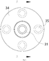
- the shaft seat 34 may have a circular plate-like structure, first fixing holes 35 are provided around a center of the circle, and the shaft seat 34 is fixed to a side edge of the battery.
- the shaft rod 31 is perpendicularly connected to the center of the shaft seat 34, the concave positioning hole 321 is provided in the end away from the shaft seat 34, and after the shaft seat 34 is fixed to the battery, the shaft rod 31 perpendicularly projects outwards.
- the first positioning steel magnet 32 is mounted in the positioning hole 321 of the shaft rod 31, and configured to provide sensing information to an external sensing device, so as to indicate the current position of the battery.
- the sleeve 33 is fitted over an outer circumference of one end of the shaft rod 31 to which the first positioning steel magnet 32 is mounted, and the sleeve 33 and the shaft rod 31 may be in a sliding relationship.
- a plurality of the lock shafts 30 may be provided, and they are fixed, through the first fixing holes 35 in the shaft seat 34, to a side edge of the battery in contact with the fixing seat of the electric vehicle.
- the positions of the fixed lock shafts 30 correspond to the positions of the lock bases 20 on the fixing seat.
- Each of the shaft rods 31 protrudes perpendicularly from the side edge of the battery.
- the battery-changing mobile platform drives the shaft rod 31 to move in the lock groove 21
- the first positioning steel magnet 32 at a front end of the shaft rod 31 passes through the sensing device mounted on the fixing seat, so that the battery-changing mobile platform clearly knows the current installation position of the battery and can make the next action in time.
- the friction between the lock shaft 30 and the lock base 20 can be reduced, the locking and unlocking processes can be improved, and clear movement state information of the battery can be offered to provide a basis for automatic unlocking and automatic locking.
- a retaining ring or a retaining flange may be provided at both ends of the shaft rod 31.
- An outwardly protruding retaining flange 36 is provided at an end of the shaft rod close to the shaft seat 34, and has a diameter larger than a diameter of the shaft rod 31, so that the sleeve 33 can be restricted at a specified position of the shaft rod 31 to achieve better contact with the lock groove 21.
- the retaining flange 36 may also prevent the shaft seat 34 from rubbing against the lock base 20 and hence avoid causing damage to the corresponding components.
- a retaining ring 331 may be provided at an end of the shaft rod 31 away from the shaft seat 34 and be configured to prevent the sleeve 33 from coming off.
- the retaining ring 331 may be mounted to the shaft rod 31 by a structure that is snapped in a groove of the shaft rod 31.
- the shaft seat 34 of the lock shaft 30 may be circular or triangular, and three to four first fixing holes 35 are provided and symmetrically distributed around the center of the shaft seat 34.
- a connecting end of the shaft rod 31 with the shaft seat 34 may pass through a shaft hole in the center of the circle and may be exposed from the other end.
- a snap ring may be provided to the passing end of the shaft rod 31 to prevent the shaft rod 31 from coming off.
- the snap ring may be mounted in the same way as the aforementioned retaining ring 331.
- the shaft rod 31 and the shaft seat 34 are movably mounted, the shaft rod 31 may be integrally formed with the shaft seat 34 in other embodiments.
- the lock connecting rod 10 may specifically include an elongated rod-like member 11, and the lock connecting rod 10 may be movably connected with a plurality of lock bases 20 to be locked through the lock tongues.
- the lock connecting rod has a length corresponding to the distance among the plurality of lock bases 20 to be locked, and a through hole 16 is provided at a position corresponding to each of the lock bases 20 and configured to be connected with the lock tongue 24 through a shaft.
- the through hole 16 facilitates the insertion of the lock tongue, and the number of the through holes 16 corresponds to the number of the lock bases.
- the rod member 11 is further provided with an unlocking block 12 on a side corresponding to the position of the lock base 20, and the unlocking block 12 is used to lift the rod member 11 under the push of the unlocking device of the battery-changing mobile platform, so that the lock connecting rod 10 drives the lock tongue 24 to switch between an unlocking state and a locking state.
- the lock connecting rod 10 When installed, the lock connecting rod 10 is connected with the lock tongue 24 through shaft and hence is located above each lock base 20, and the lock tongue 24 is also connected with the lock base 20 by a shaft, so that the rise and fall of the lock connecting rod 10 can drive the lock tongue 24 to rotate around a shaft connection point in the lock base 20, to realize the switch between the state of being snapped into the lock groove 21 and the state of leaving the lock groove 21.
- This embodiment employs a single lock connecting rod 10 to simultaneously control the lock tongues 24 of the plurality of lock bases 20, thereby realizing a function of synchronously unlocking and locking the plurality of lock bases 20, so as to improve the unlocking process of the battery and accelerate the battery replacement efficiency.
- each lock connecting rod 10 may be provided with three through holes 16, and a second fixing hole 14 may be provided in the through hole 16 and configured to be connected with the lock tongue by means of a shaft.
- Each second fixing hole 14 corresponds to and is connected with the lock tongue 24 of one lock base 20.
- the second fixing hole 14 runs through the through hole 16 in a manner perpendicular to a lateral surface of the rod member 11.
- the unlocking block 12 may be an arc protrusion formed outwardly by the rod member 11.
- the top of the unlocking block 12 is configured as an inner arc groove 121 recessed towards the rod member 11.
- the use of the arc protrusion prevents the lock connecting rod 10 from being blocked by other components during its movement.
- the arc protrusion facilitates contact with the unlocking device of the battery-changing mobile platform, to enable the unlocking device to move the lock connecting rod 10 along the arc protrusion in a transverse direction instead of being stuck in a certain position.
- the structure of the inner arc groove 121 on the top of the unlocking block 12 can form an optimal unlocking position with the unlocking device, and at this position, the lock connecting rod 10 has been fully unlocked and the retention of the unlocking device is facilitated.
- the position of the unlocking block 12 may be specifically arranged on the rod member 11 between the two through holes, as long as the movement of the lock connecting rod 10 is not affected.
- a spring pull tab 101 on the same side of the unlocking block 12 may be fixedly mounted on the rod member 11, and an exposed end of the spring pull tab 101 is provided with a hooking hole.
- the spring pull tab 101 is used to connect a spring fixed to the fixing seat of the electric vehicle, and the spring applies a pulling force to the lock connecting rod 10 towards the lock base 20 to improve the stability of the lock connecting rod 10 in the locked state.
- a second positioning steel magnet 13 may be mounted on the rod member 11, and the second positioning steel magnet 13 may generate induction with an external magnetic detecting device to determine the current position of the rod member 11 according to a sensing signal.
- the second positioning steel magnet 13 may be specifically mounted at an end of the rod member 11 and may be cylindrical; the end of the rod member 11 is provided with a steel magnet mounting hole 131 passing through the rod member 11; and the second positioning steel magnet 13 is inserted in the steel magnet positioning hole 131.
- a corresponding sensing device is provided on a moving track of the second positioning steel magnet 13. When the rod member 11 is moved, the second positioning steel magnet 13 stays at or passes through the sensing device to determine whether the lock connecting rod 10 is currently in the unlocked state or in the locked state.
Abstract
Description
- The present disclosure relates to a technical field of electric vehicles, and more particularly to a battery pack and an electric vehicle.
- A battery of an existing electric vehicle is generally installed in a fixed way or in a replaceable type. The fixed battery is usually fixed to the vehicle, and the vehicle is directly charged during charging. The replaceable battery is usually installed in a movable manner, and the battery can be removed at any time for replacement or for charging and then be installed to the vehicle body after replacement or charging.
- At present, a battery may be replaced by a manual operation or an automatic operation. Either way, the battery is mounted to a chassis of the electric vehicle, and the installed battery needs to be locked to the vehicle body. Due to a relatively large weight of the battery, a structure using multiple locking positions to lock simultaneously is employed, but an existing locking structure fails to meet requirements in terms of speed and automation.
- In addition, during a battery change process in the related art, a position of a battery pack cannot be easily determined in time, diminishing the battery change efficiency.
- The present disclosure aims to provide a battery pack and an electric vehicle, to overcome the defect in the related art that the position of the battery pack cannot be easily determined in time.
- A battery pack is provided according to an embodiment. A plurality of lock shafts is mounted on an outer side of the battery pack. Each of the lock shafts includes a shaft seat and a shaft rod; the lock shaft is mounted to the outer side of the battery pack by the shaft seat; a concave positioning hole is arranged at an end of the shaft rod away from the shaft seat, and a first positioning steel magnet is mounted in the positioning hole.
- In an embodiment of the present disclosure, the shaft seat has a circular or triangular plate-like structure.
- In an embodiment of the present disclosure, first fixing holes are provided around a center of a circle of the shaft seat, and the shaft seat is mounted to a side edge of the battery pack by the first fixing holes.
- In an embodiment of the present disclosure, three or four first fixing holes are symmetrically distributed.
- In an embodiment of the present disclosure, the shaft rod is perpendicularly arranged to a surface of the shaft seat, and shaft rod is perpendicularly connected to a center of a circle of the shaft seat.
- In an embodiment of the present disclosure, a sleeve is fitted over the shaft rod to prevent the first positioning steel magnet from coming off, the sleeve is fitted over an outer circumference of an end of the shaft rod to which the first positioning steel magnet is mounted, and the sleeve and the shaft rod are connected in a sliding manner.
- In an embodiment of the present disclosure, the shaft rod has two ends provided with a retaining ring or retaining flange, separately, and a diameter of the retaining flange is greater than a diameter of the shaft rod, and the retaining ring is snap-fitted in a groove of the shaft rod.
- In an embodiment of the present disclosure, a connecting end of the shaft rod with the shaft seat passes through a shaft hole in the center of the circle of the shaft seat and is exposed from the other end.
- In an embodiment of the present disclosure, a snap ring is arranged at a passing end of the shaft rod to prevent the shaft rod from coming off, and the snap ring is snap-fitted in a groove of the shaft rod.
- An electric vehicle include the above battery pack, a fixing seat configured to install the battery pack, and a locking device. The fixing seat is mounted to a vehicle body; the locking device is mounted to an inner lateral surface of the fixing seat opposite to the battery pack; and the locking device includes a lock base configured to provide a locking position, the lock base including a lock body having a surface provided with a lock groove recessed towards the inside of the lock body, and a lock shaft being inserted into the lock groove to perform locking.
- In an embodiment of the present disclosure, a back surface of the lock body is provided with a lock shaft sensing hole in communication with the lock groove; a sensing device is mounted at a position of the fixing seat of the vehicle body corresponding to the lock shaft sensing hole; when the lock shaft enters the lock groove, the first positioning steel magnet is sensed by the sensing device when passing through the lock shaft sensing hole, such that it is determined whether the battery currently enters the lock groove; when a battery-changing mobile platform drives the shaft rod to move in the lock groove, the first positioning steel magnet at a front end of the shaft rod passes through the sensing device mounted on the fixing seat, such that the battery-changing mobile platform obtains a current installation position of the battery and makes the next action in time.
- In an embodiment of the present disclosure, the lock body is provided with a lock tongue groove and a lock tongue movably mounted in the lock tongue groove, and the lock tongue groove is communicated with the lock groove.
- In an embodiment of the present disclosure, the lock groove extends along a surface of the lock body, and has a first end provided with an opening leading to the outside of the lock body, and a second end away from the opening and provided with an elastic pad and an elastic pad mounting hole; the elastic pad mounting hole is arranged in a side wall of the second end of the lock groove, and the elastic pad is inserted into the elastic pad mounting hole through a pillar protruding from a surface of the elastic pad.
- In an embodiment of the present disclosure, the locking device further includes a lock connecting rod movably connected with the lock base through a lock tongue. The lock connecting rod includes a rod member configured to drive the lock tongue to move under the action of an external force; the rod member is provided with an unlocking block on a side facing the lock base; the unlocking block is configured as an arc protrusion formed outwardly by the rod member; and the unlocking block has a top configured as an inner arc groove recessed towards the rod member.
- In an embodiment of the present disclosure, a spring pull tab is fixed on a side of the rod member facing the unlocking block, and an exposed end of the spring pull tab is provided with a hooking hole.
- In an embodiment of the present disclosure, the inner lateral surface of the fixing seat is located below the lock connecting rod and is further provided with an elastic component, and the elastic component has a first end fixedly connected with the fixing seat and a second end connected to the hooking hole.
- The lock shaft according to the present disclosure is provided with the positioning steel magnet which can be sensed by an external sensing device, such that the battery-changing mobile platform can obtain the current installation position of the battery and make the next action in time, improving the battery change efficiency.
- The present disclosure can fix the battery to the electric vehicle in such a way that a plurality of lock shafts distributed on a side edge of the battery are simultaneously inserted into a plurality of lock bases of the electric vehicle, and can simultaneously lock the plurality of lock shafts to the lock bases in an automatic manner by means of the action of the lock connecting rod, thereby improving the efficiency of assembling or disassembling the battery greatly.
- By adopting the above-mentioned lock groove structure, the lock base of the present disclosure can provide the battery with a balanced suspension platform, and the elastic pad arranged at the end of the lock groove can reduce the collision between the battery and the fixing seat during the installation and during driving, thereby improving the service life of various locking components.
- The lock shaft of the present disclosure can reduce the friction with the lock base, improve the locking and unlocking process, and offer clear motion state information to provide a basis for automatic unlocking and automatic locking.
- The present disclosure utilizes a single lock connecting rod to simultaneously control the lock tongues of the plurality of lock bases, realizes a function of synchronously unlocking and locking the plurality of lock bases, so as to improve the unlocking process of the battery and accelerate the battery replacement efficiency.
-
-
Fig. 1 illustrates a schematic view of a locking device according to an embodiment of the present disclosure. -
Fig. 2 illustrates a sectional view of a lock shaft along an axis according to an embodiment of the present disclosure. -
Fig. 3 illustrates a schematic view of a lock base according to an embodiment of the present disclosure. -
Fig. 4 is a perspective view ofFig. 3 . -
Fig. 5 is a right view ofFig. 4 . -
Fig. 6 illustrates a front view of a lock shaft according to an embodiment of the present disclosure. -
Fig. 7 illustrates a schematic view of a lock connecting rod according to an embodiment of the present disclosure. -
Fig. 8 illustrates a schematic view of a lock connecting rod according to an embodiment of the present disclosure. -
Fig. 9 is a top view ofFig. 8 . -
Fig. 10 is a perspective view ofFig. 9 . - As shown in
Figs. 1-6 , a locking device of an embodiment of the present disclosure generally includes alock base 20 configured to provide a locking position, alock shaft 30 configured to be inserted into thelock base 20, and alock connecting rod 10 configured to unlock thelock shaft 30 after being inserted. - The
lock base 20 includes alock body 25 having a rectangular shape. A front surface of thelock body 25 is provided with alock groove 21 recessed towards the inside of thelock body 25. Thelock base 20 further includes alock tongue groove 22 and alock tongue 24 mounted in thelock tongue groove 22. Thelock tongue groove 22 is communicated with thelock groove 21, and thelock tongue 24 is movably mounted in thelock tongue groove 22. - The
lock shaft 30 includes ashaft seat 34 having a fixing hole, and ashaft rod 31 perpendicularly arranged to a surface of theshaft seat 34 and configured to be inserted into thelock groove 21 of thelock base 20 so as to perform locking. - The
lock connecting rod 10 may include anelongated rod member 11 movably connected to thelock tongue 24 of thelock base 20. - The locking device in the embodiment can be used to lock a power battery of an electric vehicle, in which the
lock shafts 30 are mounted around a battery pack, and thelock bases 20 and thelock connecting rod 10 are mounted to an inner lateral surface of a vehicle body fixing seat for fixing the battery and arranged at positions corresponding to the positions of thelock shafts 30. As shown inFigs. 2 and3 , in an embodiment of the present disclosure, thelock groove 21 has a certain length in the horizontal direction, and thelock groove 21 has a side provided with anopening 211 communicated with a bottom surface of thelock body 25 and leading to the outside of the lock body, in which theopening 211 is used for thelock shaft 30 mounted on the battery to enter. Thelock tongue groove 22 has an opening which leads to a top surface of the lock body, and the lock tongue passes through this opening to be movably connected with thelock connecting rod 10. A side of the lock tongue adjacent to thelock groove 21 is provided with astopping device 2A, and thestopping device 2A is configured to close the opening 211 of thelock groove 21. - The
lock body 25 has a back surface fixedly fixed to the vehicle body fixing seat, and a front surface facing the battery to be installed. Thelock connecting rod 10 is movably mounted above thelock base 20 through the lock tongue. Thelock shaft 30 is mounted on an outer side of the battery pack by the shaft seat at a position corresponding to thelock base 20. - When in use, the battery enters the fixing seat from the bottom of the electric vehicle under a lifting action of a battery-changing mobile platform, and a unlocking member pushes the
lock connecting rod 10 to move upwards and drives the lock tongue to open the opening 211 of thelock groove 21, such that thelock shaft 30 around the battery is inserted into thelock groove 21 through the opening 211 of thelock groove 21 of thecorresponding lock base 20 by means of theshaft rod 31, and then is moved to the other side of thelock groove 21 under the push of the battery-changing mobile platform until the lock shaft comes into contact with the other end of the lock groove. In such a way, a suspension process of the battery is completed. During the insertion of theshaft rod 31, thelock connecting rod 10 drives the stoppingdevice 2A to move upwardly, under the push of the unlocking member, and when theshaft rod 31 enters a locking region in thelock groove 21 beyond the position of the stoppingdevice 2A, the stoppingdevice 2A falls under the gravity of thelock connecting rod 10 to laterally block a return path of theshaft rod 31. At this time, the battery is in a state of being completely locked to the electric vehicle. When the battery needs to be replaced, an unlocking device on the battery-changing mobile platform contacts thelock connecting rod 10 and pushes thelock connecting rod 10 to rise, so that the lock tongue leaves thelock groove 21, and at this time, the battery is moved to cause theshaft rod 31 to be withdrawn from thelock groove 21, thereby completing a battery removal process. - As shown in
Fig. 5 , in an embodiment of the present disclosure, anelastic pad 23 is mounted on the other end of thelock groove 21 away from theopening 211, and an elasticpad mounting hole 251 is provided in a side wall of the other end. Theelastic pad 23 may be installed in the elasticpad mounting hole 251 through apillar 231 on a surface of the elastic pad. By providing theelastic pad 23 at the other end of the lock groove, after the lock shaft is inserted into thelock groove 21, the friction between thelock shaft 30 and thelock groove 21 can be reduced to protect thelock shaft 30. This structure facilitates the installation and removal of theelastic pad 23. Thepillar 231 may adopt a tensioning structure with an opening, and after being inserted into the elasticpad mounting hole 251, the protrusion may be automatically clamped to prevent an unintentional escape of theelastic pad 23. Theelastic pad 23 may be specifically made of an organic material such as rubber or plastic, so as to have certain stiffness and meanwhile avoid causing hard damage to thelock shaft 30. - In an embodiment of the present disclosure, the
lock groove 21 may adopt an L-shaped structure, which can provide the battery with a stable suspension platform, and at the same time, theelastic pad 23 is arranged at the end of thelock groove 21, which can reduce the collision between the battery and the fixing seat during the installation and during driving, thereby improving the service life of various locking components. In other embodiments, thelock groove 21 may also adopt a curved shape or other shapes capable of providing the suspension platform. - In an embodiment of the present disclosure, the stopping
device 2A may be specifically configured as astop block 243 protruding from thelock tongue 24 towards a side of thelock groove 21, and thestop block 243 is used to close theopening 211 of thelock groove 21 to prevent theshaft rod 31 inserted into thelock groove 21 from sliding out of thelock groove 21. Thelock tongue 24 is connected in thelock tongue groove 22 through a shaft, and thelock tongue 24 includes a lock tonguegroove shaft hole 241 connected to thelock tongue groove 22, and a lock connectingrod shaft hole 242 connected to thelock connecting rod 10 which pushes thelock tongue 24 to rotate. - The
lock tongue 24 in a normal state is simultaneously connected to thelock base 20 and thelock connecting rod 10 through shafts. Since thelock connecting rod 10 is in an active state, thelock tongue 24 can be rotated about a shaft connection point with thelock base 20 by the movement of thelock connecting rod 10, so that the stop block 243 of thelock tongue 24 can be switched between a state of entering thelock groove 21 and a state of leaving thelock groove 21. Thelock connecting rod 10 is pushed to move upwards by the external unlocking device, such that the lock tongue is moved upwards, and the stop block 243 leaves thelock groove 21. Theshaft rod 31 of thelock shaft 30 enters thelock groove 21 from theopening 211, and is translated into the locking region of thelock groove 21 under the push of the battery-changing mobile platform. At this time, the unlocking device is removed, thelock connecting rod 10 moves downwards by gravity, the lock tongue is also moved downwards, and the stop block 243 blocks theopening 211 of thelock groove 21, such that the shaft rod is locked in thelock groove 21, and the corresponding battery is also stably fixed in the fixing seat of the electric vehicle. - During the battery replacement, the unlocking device on the battery-changing mobile platform pushes the
lock connecting rod 10 upwardly in an upward lifting process, and the movement of thelock connecting rod 10 naturally drives the stop block 243 of thelock tongue 24 to leave thelock groove 21. At this time, the battery can be moved to remove thelock shaft 30 from theopening 211 of thelock groove 21, thereby completing the unlocking of the battery. - In an embodiment of the present disclosure, a diameter of a first end of the
opening 211 at the bottom surface may be larger than a diameter of a second end of theopening 211 at thelock groove 21. The use of such an open structure facilitates the entry of thelock shaft 30 and also reduces the collision damage to thelock base 20. - In an embodiment of the present disclosure, the bottom surface of the
lock body 25 and the front surface of thelock body 25 may be connected through tangent surfaces. This structure can reduce the collision with thelock base 20 in a rising process of the battery. - In an embodiment of the present disclosure, the back surface of the
lock body 25 is provided with a lock shaft sensing hole in communication with thelock groove 21. A sensing device may be installed at a position of the fixing seat corresponding to the lock shaft sensing hole. When thelock shaft 30 enters thelock groove 21, a firstpositioning steel magnet 32 mounted thereon is sensed by the sensing device when passing through the lock shaft sensing hole, such that it is determined whether the battery currently enters thelock groove 21 or not, thereby determining the next action. - As shown in
Fig. 2 , in an embodiment of the present disclosure, aconcave positioning hole 321 is provided in an end of theshaft rod 31 away from theshaft seat 34, and the firstpositioning steel magnet 32 is mounted in thepositioning hole 321. Asleeve 33 is fitted over theshaft rod 31 to prevent the firstpositioning steel magnet 32 from coming off. Theshaft seat 34 may have a circular plate-like structure, first fixing holes 35 are provided around a center of the circle, and theshaft seat 34 is fixed to a side edge of the battery. Theshaft rod 31 is perpendicularly connected to the center of theshaft seat 34, theconcave positioning hole 321 is provided in the end away from theshaft seat 34, and after theshaft seat 34 is fixed to the battery, theshaft rod 31 perpendicularly projects outwards. The firstpositioning steel magnet 32 is mounted in thepositioning hole 321 of theshaft rod 31, and configured to provide sensing information to an external sensing device, so as to indicate the current position of the battery. Thesleeve 33 is fitted over an outer circumference of one end of theshaft rod 31 to which the firstpositioning steel magnet 32 is mounted, and thesleeve 33 and theshaft rod 31 may be in a sliding relationship. - In the present embodiment, a plurality of the
lock shafts 30 may be provided, and they are fixed, through the first fixing holes 35 in theshaft seat 34, to a side edge of the battery in contact with the fixing seat of the electric vehicle. The positions of the fixedlock shafts 30 correspond to the positions of the lock bases 20 on the fixing seat. Each of theshaft rods 31 protrudes perpendicularly from the side edge of the battery. When the battery is snapped into the fixing seat of the electric vehicle under the control of the battery-changing mobile platform, theshaft rods 31 of thelock shafts 30 are inserted into thelock grooves 21 of the corresponding lock bases 20, and the friction of theshaft rod 31 in the moving contact with thelock groove 21 can be reduced by thesleeve 33. When the battery-changing mobile platform drives theshaft rod 31 to move in thelock groove 21, the firstpositioning steel magnet 32 at a front end of theshaft rod 31 passes through the sensing device mounted on the fixing seat, so that the battery-changing mobile platform clearly knows the current installation position of the battery and can make the next action in time. - In the present embodiment, the friction between the
lock shaft 30 and thelock base 20 can be reduced, the locking and unlocking processes can be improved, and clear movement state information of the battery can be offered to provide a basis for automatic unlocking and automatic locking. - In an embodiment of the present disclosure, in order to define the position of the
sleeve 33, a retaining ring or a retaining flange may be provided at both ends of theshaft rod 31. An outwardly protruding retainingflange 36 is provided at an end of the shaft rod close to theshaft seat 34, and has a diameter larger than a diameter of theshaft rod 31, so that thesleeve 33 can be restricted at a specified position of theshaft rod 31 to achieve better contact with thelock groove 21. The retainingflange 36 may also prevent theshaft seat 34 from rubbing against thelock base 20 and hence avoid causing damage to the corresponding components. Further, a retainingring 331 may be provided at an end of theshaft rod 31 away from theshaft seat 34 and be configured to prevent thesleeve 33 from coming off. The retainingring 331 may be mounted to theshaft rod 31 by a structure that is snapped in a groove of theshaft rod 31. - In order to facilitate the fixation of the
lock shaft 30, in an embodiment of the present disclosure, theshaft seat 34 of thelock shaft 30 may be circular or triangular, and three to four first fixing holes 35 are provided and symmetrically distributed around the center of theshaft seat 34. - In an embodiment of the present disclosure, a connecting end of the
shaft rod 31 with theshaft seat 34 may pass through a shaft hole in the center of the circle and may be exposed from the other end. A snap ring may be provided to the passing end of theshaft rod 31 to prevent theshaft rod 31 from coming off. The snap ring may be mounted in the same way as theaforementioned retaining ring 331. Although theshaft rod 31 and theshaft seat 34 are movably mounted, theshaft rod 31 may be integrally formed with theshaft seat 34 in other embodiments. - As shown in
Figs. 7-10 , in an embodiment of the present disclosure, thelock connecting rod 10 may specifically include an elongated rod-like member 11, and thelock connecting rod 10 may be movably connected with a plurality oflock bases 20 to be locked through the lock tongues. The lock connecting rod has a length corresponding to the distance among the plurality oflock bases 20 to be locked, and a throughhole 16 is provided at a position corresponding to each of the lock bases 20 and configured to be connected with thelock tongue 24 through a shaft. The throughhole 16 facilitates the insertion of the lock tongue, and the number of the throughholes 16 corresponds to the number of the lock bases. Therod member 11 is further provided with an unlockingblock 12 on a side corresponding to the position of thelock base 20, and the unlockingblock 12 is used to lift therod member 11 under the push of the unlocking device of the battery-changing mobile platform, so that thelock connecting rod 10 drives thelock tongue 24 to switch between an unlocking state and a locking state. - When installed, the
lock connecting rod 10 is connected with thelock tongue 24 through shaft and hence is located above eachlock base 20, and thelock tongue 24 is also connected with thelock base 20 by a shaft, so that the rise and fall of thelock connecting rod 10 can drive thelock tongue 24 to rotate around a shaft connection point in thelock base 20, to realize the switch between the state of being snapped into thelock groove 21 and the state of leaving thelock groove 21. This embodiment employs a singlelock connecting rod 10 to simultaneously control thelock tongues 24 of the plurality oflock bases 20, thereby realizing a function of synchronously unlocking and locking the plurality oflock bases 20, so as to improve the unlocking process of the battery and accelerate the battery replacement efficiency. - The
rod member 11 of eachlock connecting rod 10 may be provided with three throughholes 16, and asecond fixing hole 14 may be provided in the throughhole 16 and configured to be connected with the lock tongue by means of a shaft. Eachsecond fixing hole 14 corresponds to and is connected with thelock tongue 24 of onelock base 20. Thesecond fixing hole 14 runs through the throughhole 16 in a manner perpendicular to a lateral surface of therod member 11. - In an embodiment of the present disclosure, the unlocking
block 12 may be an arc protrusion formed outwardly by therod member 11. The top of the unlockingblock 12 is configured as aninner arc groove 121 recessed towards therod member 11. The use of the arc protrusion prevents thelock connecting rod 10 from being blocked by other components during its movement. At this time, the arc protrusion facilitates contact with the unlocking device of the battery-changing mobile platform, to enable the unlocking device to move thelock connecting rod 10 along the arc protrusion in a transverse direction instead of being stuck in a certain position. The structure of theinner arc groove 121 on the top of the unlockingblock 12 can form an optimal unlocking position with the unlocking device, and at this position, thelock connecting rod 10 has been fully unlocked and the retention of the unlocking device is facilitated. The position of the unlockingblock 12 may be specifically arranged on therod member 11 between the two through holes, as long as the movement of thelock connecting rod 10 is not affected. - In an embodiment of the present disclosure, a
spring pull tab 101 on the same side of the unlockingblock 12 may be fixedly mounted on therod member 11, and an exposed end of thespring pull tab 101 is provided with a hooking hole. Thespring pull tab 101 is used to connect a spring fixed to the fixing seat of the electric vehicle, and the spring applies a pulling force to thelock connecting rod 10 towards thelock base 20 to improve the stability of thelock connecting rod 10 in the locked state. - In an embodiment of the present disclosure, in order to determine the current position of the
lock connecting rod 10, a secondpositioning steel magnet 13 may be mounted on therod member 11, and the secondpositioning steel magnet 13 may generate induction with an external magnetic detecting device to determine the current position of therod member 11 according to a sensing signal. - The second
positioning steel magnet 13 may be specifically mounted at an end of therod member 11 and may be cylindrical; the end of therod member 11 is provided with a steelmagnet mounting hole 131 passing through therod member 11; and the secondpositioning steel magnet 13 is inserted in the steelmagnet positioning hole 131. A corresponding sensing device is provided on a moving track of the secondpositioning steel magnet 13. When therod member 11 is moved, the secondpositioning steel magnet 13 stays at or passes through the sensing device to determine whether thelock connecting rod 10 is currently in the unlocked state or in the locked state. - It would be appreciated by those skilled in the art that various exemplary embodiments of the present disclosure have been shown and described in detail, but many other variations or modifications consistent with the principles of the present disclosure may be directly determined or derived based on the present disclosure without departing from the scope of the present disclosure. Therefore, the scope of the present disclosure should be understood and construed to cover all such other variations or modifications.
Claims (16)
- A battery pack, wherein a plurality of lock shafts (30) are mounted on an outer side of the battery pack, and each of the lock shafts (30) comprises a shaft seat (34) and a shaft rod (31); the lock shaft (30) is mounted to the outer side of the battery pack by the shaft seat (34); a concave positioning hole (321) is arranged at an end of the shaft rod (31) away from the shaft seat (34), and a first positioning steel magnet (32) is mounted in the positioning hole (321).
- The battery pack according to claim 1, wherein the shaft seat (34) has a circular or triangular plate-like structure.
- The battery pack according to claim 2, wherein first fixing holes (35) are provided around a center of a circle of the shaft seat (34), and the shaft seat (34) is mounted to a side edge of the battery pack by the first fixing holes (35).
- The battery pack according to claim 3, wherein three or four first fixing holes (35) are symmetrically distributed.
- The battery pack according to claim 2, wherein the shaft rod (31) is perpendicularly arranged to a surface of the shaft seat (34), and the shaft rod (31) is perpendicularly connected to a center of a circle of the shaft seat (34).
- The battery pack according to any one of claims 1 to 5, wherein a sleeve (33) is fitted over the shaft rod (31) to prevent the first positioning steel magnet (32) from coming off, the sleeve (33) is fitted over an outer circumference of an end of the shaft rod (31) to which the first positioning steel magnet (32) is mounted, and the sleeve (33) and the shaft rod (31) are connected in a sliding manner.
- The battery pack according to claim 6, wherein the shaft rod (31) has two ends provided with a retaining ring (331) or retaining flange (36), separately, and a diameter of the retaining flange (36) is greater than a diameter of the shaft rod (31), and the retaining ring (331) is snap-fitted in a groove of the shaft rod (31).
- The battery pack according to claim 5, wherein a connecting end of the shaft rod (31) with the shaft seat (34) passes through a shaft hole in the center of the circle of the shaft seat (34) and is exposed from the other end.
- The battery pack according to claim 8, wherein a snap ring is arranged at a passing end of the shaft rod (31) to prevent the shaft rod (31) from coming off, and the snap ring is snap-fitted in a groove of the shaft rod (31).
- An electric vehicle, comprising a battery pack according to any one of claims 1 to 9, a fixing seat configured to install the battery pack, and a locking device, wherein the fixing seat is mounted to a vehicle body; the locking device is mounted to an inner lateral surface of the fixing seat opposite to the battery pack; and the locking device comprises a lock base (20) configured to provide a locking position, the lock base (20) comprising a lock body (25) having a surface provided with a lock groove (21) recessed towards the inside of the lock body (25), and a lock shaft (30) being inserted into the lock groove (21) to perform locking.
- The electric vehicle according to claim 10, wherein a back surface of the lock body (25) is provided with a lock shaft sensing hole in communication with the lock groove (21); a sensing device is mounted at a position of the fixing seat of the vehicle body corresponding to the lock shaft sensing hole; when the lock shaft (30) enters the lock groove (21), the first positioning steel magnet (32) is sensed by the sensing device when passing through the lock shaft sensing hole, such that it is determined whether the battery currently enters the lock groove (21); when a battery-changing mobile platform drives the shaft rod (31) to move in the lock groove (21), the first positioning steel magnet (32) at a front end of the shaft rod (31) passes through the sensing device mounted on the fixing seat, such that the battery-changing mobile platform obtains a current installation position of the battery and makes the next action in time.
- The electric vehicle according to claim 10, wherein the lock body (25) is provided with a lock tongue groove (22) and a lock tongue movably mounted in the lock tongue groove (22), and the lock tongue groove (22) is communicated with the lock groove (21).
- The electric vehicle according to claim 11, wherein the lock groove (21) extends along a surface of the lock body (25), and has a first end provided with an opening leading to the outside of the lock body (25), and a second end away from the opening and provided with an elastic pad (23) and an elastic pad mounting hole (251); the elastic pad mounting hole (251) is arranged in a side wall of the second end of the lock groove (21), and the elastic pad (23) is inserted into the elastic pad mounting hole (251) through a pillar (231) protruding from a surface of the elastic pad (23).
- The electric vehicle according to claim 13, wherein the locking device further comprises a lock connecting rod (10) movably connected with the lock base (20) through a lock tongue (24), wherein the lock connecting rod (10) comprises a rod member (11) configured to drive the lock tongue (24) to move under the action of an external force; the rod member (11) is provided with an unlocking block (12) on a side facing the lock base (20); the unlocking block (12) is configured as an arc protrusion formed outwardly by the rod member (11); and the unlocking block (12) has a top configured as an inner arc groove recessed towards the rod member (11).
- The electric vehicle according to claim 14, wherein a spring pull tab (101) is fixed on a side of the rod member (11) facing the unlocking block (12), and an exposed end of the spring pull tab (101) is provided with a hooking hole.
- The electric vehicle according to claim 15, wherein the inner lateral surface of the fixing seat is located below the lock connecting rod (10) and is further provided with an elastic component, and the elastic component has a first end fixedly connected with the fixing seat and a second end connected to the hooking hole.
Applications Claiming Priority (3)
| Application Number | Priority Date | Filing Date | Title |
|---|---|---|---|
| CN201611041220.4A CN106427514B (en) | 2016-11-21 | 2016-11-21 | Locking device and electric automobile |
| PCT/CN2017/111994 WO2018090996A1 (en) | 2016-11-21 | 2017-11-21 | Locking device, fixed base and electric vehicle |
| EP17871600.7A EP3543078B1 (en) | 2016-11-21 | 2017-11-21 | Locking device, fixed base and electric vehicle |
Related Parent Applications (2)
| Application Number | Title | Priority Date | Filing Date |
|---|---|---|---|
| EP17871600.7A Division EP3543078B1 (en) | 2016-11-21 | 2017-11-21 | Locking device, fixed base and electric vehicle |
| EP17871600.7A Division-Into EP3543078B1 (en) | 2016-11-21 | 2017-11-21 | Locking device, fixed base and electric vehicle |
Publications (1)
| Publication Number | Publication Date |
|---|---|
| EP4026716A1 true EP4026716A1 (en) | 2022-07-13 |
Family
ID=58218076
Family Applications (4)
| Application Number | Title | Priority Date | Filing Date |
|---|---|---|---|
| EP17871600.7A Active EP3543078B1 (en) | 2016-11-21 | 2017-11-21 | Locking device, fixed base and electric vehicle |
| EP22159245.4A Pending EP4026741A1 (en) | 2016-11-21 | 2017-11-21 | Locking device and electric vehicle |
| EP22159244.7A Pending EP4026740A1 (en) | 2016-11-21 | 2017-11-21 | Locking method and unlocking method |
| EP22159247.0A Pending EP4026716A1 (en) | 2016-11-21 | 2017-11-21 | Battery pack and electric vehicle |
Family Applications Before (3)
| Application Number | Title | Priority Date | Filing Date |
|---|---|---|---|
| EP17871600.7A Active EP3543078B1 (en) | 2016-11-21 | 2017-11-21 | Locking device, fixed base and electric vehicle |
| EP22159245.4A Pending EP4026741A1 (en) | 2016-11-21 | 2017-11-21 | Locking device and electric vehicle |
| EP22159244.7A Pending EP4026740A1 (en) | 2016-11-21 | 2017-11-21 | Locking method and unlocking method |
Country Status (11)
| Country | Link |
|---|---|
| US (4) | US11364781B2 (en) |
| EP (4) | EP3543078B1 (en) |
| JP (2) | JP6912593B2 (en) |
| KR (4) | KR102308689B1 (en) |
| CN (8) | CN114103720A (en) |
| ES (1) | ES2921703T3 (en) |
| MX (3) | MX2019005909A (en) |
| PL (1) | PL3543078T3 (en) |
| SG (1) | SG10202107731UA (en) |
| WO (1) | WO2018090996A1 (en) |
| ZA (1) | ZA201903225B (en) |
Families Citing this family (36)
| Publication number | Priority date | Publication date | Assignee | Title |
|---|---|---|---|---|
| CN114103720A (en) * | 2016-11-21 | 2022-03-01 | 上海电巴新能源科技有限公司 | Battery pack and electric automobile |
| CN108132641B (en) * | 2017-04-01 | 2020-10-23 | 上海电巴新能源科技有限公司 | Control method and system of stacker crane and electric vehicle battery replacement control method and system |
| EP3718838A4 (en) * | 2017-11-30 | 2021-09-01 | Shanghai Dianba New Energy Technology Co., Ltd. | Battery locking/unlocking system, and electric vehicle battery swapping control system and control method thereof |
| CN109895750A (en) | 2017-12-08 | 2019-06-18 | 上海电巴新能源科技有限公司 | Change electric system |
| CN111933851B (en) * | 2017-12-29 | 2023-01-31 | 上海电巴新能源科技有限公司 | Supporting device, battery fixing seat and electric vehicle |
| CN113910968B (en) * | 2017-12-29 | 2024-02-13 | 上海电巴新能源科技有限公司 | Locking mechanism for battery pack, locking assembly, quick-change bracket assembly and electric vehicle |
| CN109986941B (en) * | 2017-12-29 | 2021-07-16 | 上海电巴新能源科技有限公司 | Locking mechanism, quick change bracket component and electric automobile |
| CN109987063B (en) * | 2017-12-29 | 2022-06-10 | 上海电巴新能源科技有限公司 | Battery replacing equipment for horizontally installing and taking battery and battery disassembling and installing method |
| CN114161988B (en) * | 2017-12-29 | 2024-02-13 | 上海电巴新能源科技有限公司 | Locking system and quick-change bracket assembly comprising same |
| BR112020013375A2 (en) | 2017-12-29 | 2020-12-01 | Shanghai Dianba New Energy Technology Co., Ltd. | locking mechanism, locking system, quick-change bracket assembly and electronic vehicle |
| ES2939953T3 (en) | 2017-12-29 | 2023-04-28 | Shanghai Dianba New Energy Tech Co Ltd | Lock mechanism, lock assembly, quick change support frame assembly and electric vehicle |
| WO2019129287A1 (en) * | 2017-12-29 | 2019-07-04 | 上海电巴新能源科技有限公司 | Unlocking mechanism for battery pack, locking device comprising same, and power changing device |
| CN114400411A (en) * | 2017-12-29 | 2022-04-26 | 上海电巴新能源科技有限公司 | Trade spacing subassembly of electricity direction, battery package assembly and contain its electric motor car |
| KR102437941B1 (en) | 2017-12-29 | 2022-08-29 | 상하이 디안바 뉴 에너지 테크놀러지 코., 엘티디. | Battery holder, battery exchange device, electric vehicle and installation method for electric vehicle |
| CN110203071B (en) * | 2018-02-28 | 2022-05-06 | 奥动新能源汽车科技有限公司 | Electric automobile and battery box detection device thereof |
| DE102018212574B3 (en) * | 2018-07-27 | 2019-09-05 | Robert Bosch Gmbh | Holding system for an energy storage and two-wheeler with this holding system |
| JP2022538315A (en) * | 2019-06-27 | 2022-09-01 | 奥動新能源汽車科技有限公司 | Positioning seats, positioning pins, positioning mechanisms, quick change holder parts and electric vehicles |
| CN112477677B (en) * | 2019-09-10 | 2022-11-22 | 广州汽车集团股份有限公司 | Battery quick change mechanism and car |
| CN110509756A (en) * | 2019-09-12 | 2019-11-29 | 博众精工科技股份有限公司 | A kind of displacement unlocking mechanism changes level platform |
| CN113733884B (en) * | 2020-05-13 | 2023-07-25 | 帝亚一维新能源汽车有限公司 | Battery pack quick-change fixing structure of portable battery-change electric vehicle |
| CN216648459U (en) * | 2020-09-17 | 2022-05-31 | 奥动新能源汽车科技有限公司 | Battery pack for horizontal hanging connection on electric automobile and electric automobile |
| CN114312445B (en) * | 2020-09-30 | 2023-05-12 | 奥动新能源汽车科技有限公司 | Locking control and unlocking control method and system for battery pack |
| CN112389179B (en) * | 2020-10-10 | 2022-04-26 | 东风汽车集团有限公司 | Vehicle battery package locking and unlocking device and assembly |
| EP3988359B1 (en) * | 2020-10-26 | 2023-08-30 | Volvo Truck Corporation | An energy storage mounting system |
| CN115347310A (en) * | 2021-01-15 | 2022-11-15 | 张木念 | Unmanned aerial vehicle battery compartment |
| CN113320373B (en) * | 2021-06-30 | 2022-07-22 | 东风柳州汽车有限公司 | Fixing assembly, battery pack assembly and vehicle |
| CN113715687B (en) * | 2021-09-30 | 2023-07-21 | 北京胜能能源科技有限公司 | Method and device for detecting battery state of vehicle, electronic equipment and vehicle |
| CN114217133B (en) * | 2021-11-16 | 2024-03-29 | 国网辽宁省电力有限公司大连供电公司 | State monitoring system based on Internet of things of power system |
| CN115312958A (en) * | 2021-11-30 | 2022-11-08 | 奥动新能源汽车科技有限公司 | Battery package subassembly reaches electric automobile including it |
| CN114542556B (en) * | 2022-03-21 | 2023-09-12 | 山西支点科技有限公司 | Quick dismantling/locking mechanical structure |
| CN115450993A (en) * | 2022-04-02 | 2022-12-09 | 奥动新能源汽车科技有限公司 | Unlocking assembly |
| CN114789672A (en) * | 2022-04-11 | 2022-07-26 | 中国第一汽车股份有限公司 | Self-locking battery quick-change device with vehicle-end control function, vehicle and method |
| CN114454703B (en) * | 2022-04-12 | 2022-06-28 | 中国重汽集团济南动力有限公司 | Electric automobile battery locking device, electric automobile and battery replacing method |
| CN115131918B (en) * | 2022-06-29 | 2023-07-18 | 惠州市贝斯天泰科技有限公司 | Mobile shared charging product based on plastic product |
| CN115465070B (en) * | 2022-09-21 | 2023-03-10 | 上海理工大学 | New energy automobile battery changes device with hidden handle |
| CN116607379B (en) * | 2023-05-23 | 2024-02-23 | 中国水利水电第三工程局有限公司 | Road surface patching device |
Citations (4)
| Publication number | Priority date | Publication date | Assignee | Title |
|---|---|---|---|---|
| CN102673361A (en) * | 2012-05-28 | 2012-09-19 | 奇瑞汽车股份有限公司 | Mechanism and method for quickly exchanging power battery of electric automobile |
| CN202764685U (en) * | 2012-07-24 | 2013-03-06 | 上海电巴新能源科技有限公司 | Clamping mechanism and locking device |
| CN105109321A (en) * | 2015-08-20 | 2015-12-02 | 北京新能源汽车股份有限公司 | Locking mechanism, quick battery pack replacing device with same and vehicle |
| CN105150820A (en) * | 2015-10-19 | 2015-12-16 | 北京新能源汽车股份有限公司 | Battery pack quick-changing control system for electric automobile |
Family Cites Families (57)
| Publication number | Priority date | Publication date | Assignee | Title |
|---|---|---|---|---|
| US3799063A (en) * | 1972-08-16 | 1974-03-26 | D Reed | Vehicle battery changing device |
| FR2354897A1 (en) * | 1976-06-17 | 1978-01-13 | Peugeot | DEVICE FOR THE QUICK EXCHANGE OF AN ACCUMULATOR BATTERY ON AN ELECTRIC VEHICLE |
| US4365681A (en) * | 1980-12-22 | 1982-12-28 | General Motors Corporation | Battery support structure |
| US6631775B1 (en) * | 2000-07-06 | 2003-10-14 | George T. Chaney | Electric vehicle chassis with removable battery module and a method for battery module replacement |
| US7602143B2 (en) * | 2005-11-04 | 2009-10-13 | Peter David Capizzo | System for replenishing energy sources onboard different types of automotive vehicles |
| US8006793B2 (en) * | 2008-09-19 | 2011-08-30 | Better Place GmbH | Electric vehicle battery system |
| US20110223459A1 (en) | 2008-09-19 | 2011-09-15 | Yoav Heichal | Multi-Motor Latch Assembly |
| JP2010125867A (en) * | 2008-11-25 | 2010-06-10 | Nissan Motor Co Ltd | Battery fixing structure of electric powered vehicle |
| JP2010129181A (en) * | 2008-11-25 | 2010-06-10 | Nissan Motor Co Ltd | Battery fastening structure and battery fastening method of motor-driven vehicle |
| FR2946593B1 (en) * | 2009-06-16 | 2013-02-08 | Renault Sas | SECURE ARRANGEMENT OF A BATTERY IN A MOTOR VEHICLE |
| JP5136539B2 (en) * | 2009-11-06 | 2013-02-06 | 株式会社豊田自動織機 | Electric vehicle battery mounting structure |
| US8256553B2 (en) * | 2010-02-17 | 2012-09-04 | Roberto De Paschoal | Electric vehicles |
| CN102858570B (en) * | 2010-04-08 | 2016-03-23 | 马格纳斯泰尔汽车技术两合公司 | Anchor fitting |
| US8858152B1 (en) * | 2010-05-06 | 2014-10-14 | Steven D. McDaniel | System for replacing batteries in electric cars |
| CN101890941A (en) * | 2010-07-16 | 2010-11-24 | 李立国 | Lockout mechanism for battery box |
| JP5273187B2 (en) * | 2011-03-15 | 2013-08-28 | 株式会社豊田自動織機 | Vehicle battery exchange device |
| CN202098262U (en) * | 2011-05-27 | 2012-01-04 | 山东鲁能智能技术有限公司 | Battery box locking mechanism for electric automobile chassis |
| JP5141795B2 (en) * | 2011-06-20 | 2013-02-13 | 株式会社豊田自動織機 | Battery unit mounting device for vehicle |
| US8925983B2 (en) * | 2011-06-20 | 2015-01-06 | Kabushiki Kaisha Toyota Jidoshokki | Locking apparatus for vehicle |
| CN102390364B (en) * | 2011-08-09 | 2014-07-02 | 上海电巴新能源科技有限公司 | Locking device for vehicle-mounted power battery |
| CN202417086U (en) * | 2011-11-15 | 2012-09-05 | 中国电力科学研究院 | Unlocking device for vehicular power battery box |
| JP5737162B2 (en) * | 2011-12-06 | 2015-06-17 | 株式会社豊田自動織機 | Battery unit mounting device for electric vehicle and battery unit transfer device for electric vehicle |
| JP6004774B2 (en) * | 2011-12-16 | 2016-10-12 | モテックス プロダクツ カンパニー リミテッド | Battery removal device for electric vehicles |
| FR2988041B1 (en) * | 2012-03-15 | 2014-02-28 | Renault Sas | SYSTEM FOR LOCKING / UNLOCKING AN OBJECT UNDER A RECOVERY AND SUPPORT CROCHET STRUCTURE |
| CN102785562B (en) * | 2012-08-08 | 2015-07-01 | 沈阳中科正方新能源技术有限公司 | Battery positioning locking and unlocking system of electric vehicle |
| CN202767682U (en) * | 2012-08-29 | 2013-03-06 | 宁波生久柜锁有限公司 | Strike-type hasp of electric car |
| FR2994894B1 (en) * | 2012-08-30 | 2015-06-05 | Renault Sa | ARRANGEMENT HAVING A RETENTION MECHANISM OF AN ENERGY STORAGE DEVICE, AND VEHICLE THEREFOR |
| CN202782627U (en) * | 2012-09-17 | 2013-03-13 | 上海电巴新能源科技有限公司 | Power battery locking device for electric charging electromobile |
| CN202743033U (en) * | 2012-09-18 | 2013-02-20 | 国家电网公司 | Locking device and battery box |
| JP6036315B2 (en) * | 2013-01-11 | 2016-11-30 | 株式会社豊田自動織機 | Lock structure |
| CN103321510B (en) * | 2013-06-19 | 2017-06-16 | 国家电网公司 | A kind of mechanical button lock |
| CN203644363U (en) | 2013-11-25 | 2014-06-11 | 陕西银河网电科技有限公司 | Vehicle-mounted advertisement screen |
| JP6036667B2 (en) * | 2013-12-04 | 2016-11-30 | 株式会社豊田自動織機 | Battery unit holding device for vehicle |
| CN104724080B (en) * | 2013-12-20 | 2017-04-12 | 国家电网公司 | Unlocking device |
| CN204161073U (en) * | 2014-10-10 | 2015-02-18 | 杭州厚达自动化系统有限公司 | For the power supply rack of magnetic steering load-carrying vehicle |
| JP6418385B2 (en) * | 2014-10-22 | 2018-11-07 | 三菱自動車工業株式会社 | Charging connector lock device |
| DK3227133T3 (en) * | 2014-12-04 | 2021-10-04 | HTLC IP Holdings No 1 Pty Ltd | AN APPARATUS AND SYSTEM FOR PROVIDING A SECONDARY POWER SOURCE FOR AN ELECTRIC VEHICLE |
| CN105083236B (en) * | 2015-05-29 | 2017-08-29 | 谢子聪 | A kind of control system of electric passenger vehicle dynamic battery changing |
| CN205034089U (en) * | 2015-10-08 | 2016-02-17 | 北京新能源汽车股份有限公司 | Electric automobile's power battery's quick change system |
| CN205081160U (en) * | 2015-11-11 | 2016-03-09 | 林德(中国)叉车有限公司 | Battery securing device is changed to side |
| CN105437945A (en) * | 2015-11-17 | 2016-03-30 | 简式国际汽车设计(北京)有限公司 | Locking mechanism of rechargeable battery box for electric passenger vehicle |
| CN105383276B (en) * | 2015-11-19 | 2019-08-27 | 简式国际汽车设计(北京)有限公司 | Electric installation is changed in a kind of electric car side |
| CN205429031U (en) | 2016-02-03 | 2016-08-03 | 浙江诺力机械股份有限公司 | Storage battery keying constructs |
| US9758030B2 (en) * | 2016-02-09 | 2017-09-12 | NextEv USA, Inc. | Replaceable battery assembly having a latching mechanism |
| US9722223B1 (en) * | 2016-03-02 | 2017-08-01 | Ford Global Technologies, Llc | Battery pack retention assembly and method |
| CN105857048B (en) * | 2016-05-06 | 2018-01-05 | 臻昊(北京)新能源科技有限公司 | A kind of generalization monoblock type battery change system for electric automobile |
| CN205573600U (en) * | 2016-05-10 | 2016-09-14 | 上海电巴新能源科技有限公司 | Passenger car locking detection device |
| CN105946609B (en) * | 2016-05-11 | 2018-05-04 | 北京新能源汽车股份有限公司 | Connection status monitoring method and device for the quick change battery of electric automobile |
| CN106080159B (en) * | 2016-05-25 | 2019-03-22 | 上海蔚来汽车有限公司 | Lock body component, power battery, its lockable mechanism and application method, the vehicles |
| US10230083B2 (en) * | 2016-11-01 | 2019-03-12 | Ford Global Technologies, Llc | Traction battery retention assembly |
| CN206186768U (en) * | 2016-11-21 | 2017-05-24 | 上海电巴新能源科技有限公司 | Locking means and electric automobile |
| CN114103720A (en) | 2016-11-21 | 2022-03-01 | 上海电巴新能源科技有限公司 | Battery pack and electric automobile |
| KR102437941B1 (en) * | 2017-12-29 | 2022-08-29 | 상하이 디안바 뉴 에너지 테크놀러지 코., 엘티디. | Battery holder, battery exchange device, electric vehicle and installation method for electric vehicle |
| CN115139773A (en) * | 2017-12-29 | 2022-10-04 | 上海电巴新能源科技有限公司 | Battery box unlocking device, battery box and battery box quick battery changing system |
| CN112368879A (en) * | 2018-06-22 | 2021-02-12 | 株式会社杰士汤浅国际 | Electricity storage device |
| US11177531B2 (en) * | 2018-08-31 | 2021-11-16 | David Kinnich | Apparatus and system for locking a battery to a transportation device |
| CN113241493B (en) * | 2021-05-11 | 2023-09-26 | 中创新航科技股份有限公司 | Battery pack box, battery pack with box and vehicle with battery pack |
-
2016
- 2016-11-21 CN CN202111531724.5A patent/CN114103720A/en active Pending
- 2016-11-21 CN CN202111530178.3A patent/CN114148211B/en active Active
- 2016-11-21 CN CN201611041220.4A patent/CN106427514B/en active Active
- 2016-11-21 CN CN202111530179.8A patent/CN114148212A/en active Pending
- 2016-11-21 CN CN202111531725.XA patent/CN114103721A/en active Pending
- 2016-11-21 CN CN202111531730.0A patent/CN114103722B/en active Active
- 2016-11-21 CN CN202111530177.9A patent/CN114148210B/en active Active
- 2016-11-21 CN CN202111528962.0A patent/CN113997826B/en active Active
-
2017
- 2017-11-21 SG SG10202107731UA patent/SG10202107731UA/en unknown
- 2017-11-21 EP EP17871600.7A patent/EP3543078B1/en active Active
- 2017-11-21 EP EP22159245.4A patent/EP4026741A1/en active Pending
- 2017-11-21 MX MX2019005909A patent/MX2019005909A/en unknown
- 2017-11-21 EP EP22159244.7A patent/EP4026740A1/en active Pending
- 2017-11-21 KR KR1020217019440A patent/KR102308689B1/en active IP Right Grant
- 2017-11-21 PL PL17871600.7T patent/PL3543078T3/en unknown
- 2017-11-21 JP JP2019547750A patent/JP6912593B2/en active Active
- 2017-11-21 KR KR1020217007997A patent/KR102270497B1/en active IP Right Grant
- 2017-11-21 US US16/462,828 patent/US11364781B2/en active Active
- 2017-11-21 KR KR1020217031128A patent/KR102420304B1/en active IP Right Grant
- 2017-11-21 ES ES17871600T patent/ES2921703T3/en active Active
- 2017-11-21 KR KR1020197017972A patent/KR102231149B1/en active IP Right Grant
- 2017-11-21 EP EP22159247.0A patent/EP4026716A1/en active Pending
- 2017-11-21 WO PCT/CN2017/111994 patent/WO2018090996A1/en unknown
-
2019
- 2019-05-20 MX MX2022012258A patent/MX2022012258A/en unknown
- 2019-05-20 MX MX2022012230A patent/MX2022012230A/en unknown
- 2019-05-22 ZA ZA2019/03225A patent/ZA201903225B/en unknown
-
2021
- 2021-07-08 JP JP2021113337A patent/JP7258957B2/en active Active
-
2022
- 2022-05-09 US US17/739,499 patent/US11958351B2/en active Active
- 2022-05-09 US US17/739,546 patent/US20220258589A1/en active Pending
- 2022-05-09 US US17/739,522 patent/US20220258588A1/en active Pending
Patent Citations (4)
| Publication number | Priority date | Publication date | Assignee | Title |
|---|---|---|---|---|
| CN102673361A (en) * | 2012-05-28 | 2012-09-19 | 奇瑞汽车股份有限公司 | Mechanism and method for quickly exchanging power battery of electric automobile |
| CN202764685U (en) * | 2012-07-24 | 2013-03-06 | 上海电巴新能源科技有限公司 | Clamping mechanism and locking device |
| CN105109321A (en) * | 2015-08-20 | 2015-12-02 | 北京新能源汽车股份有限公司 | Locking mechanism, quick battery pack replacing device with same and vehicle |
| CN105150820A (en) * | 2015-10-19 | 2015-12-16 | 北京新能源汽车股份有限公司 | Battery pack quick-changing control system for electric automobile |
Also Published As
Similar Documents
| Publication | Publication Date | Title |
|---|---|---|
| US20220258589A1 (en) | Battery pack and electric vehicle | |
| US20220109311A1 (en) | Battery holder, power transfer device, electric vehicle and installation method for electric vehicle | |
| CN110228498A (en) | The dustproof cover and gauge-changeable wheelsets of gauge-changeable wheelsets retaining mechanism | |
| CN102493984A (en) | Connecting piece | |
| US9384776B2 (en) | Clamping device of spindle motor including case having inclination surface | |
| KR20080105815A (en) | Clamping apparatus of spindle motor | |
| CN110806418A (en) | X-ray detection device based on five-axis motion platform |
Legal Events
| Date | Code | Title | Description |
|---|---|---|---|
| PUAI | Public reference made under article 153(3) epc to a published international application that has entered the european phase |
Free format text: ORIGINAL CODE: 0009012 |
|
| STAA | Information on the status of an ep patent application or granted ep patent |
Free format text: STATUS: THE APPLICATION HAS BEEN PUBLISHED |
|
| AC | Divisional application: reference to earlier application |
Ref document number: 3543078 Country of ref document: EP Kind code of ref document: P |
|
| AK | Designated contracting states |
Kind code of ref document: A1 Designated state(s): AL AT BE BG CH CY CZ DE DK EE ES FI FR GB GR HR HU IE IS IT LI LT LU LV MC MK MT NL NO PL PT RO RS SE SI SK SM TR |
|
| STAA | Information on the status of an ep patent application or granted ep patent |
Free format text: STATUS: REQUEST FOR EXAMINATION WAS MADE |
|
| 17P | Request for examination filed |
Effective date: 20230110 |
|
| RBV | Designated contracting states (corrected) |
Designated state(s): AL AT BE BG CH CY CZ DE DK EE ES FI FR GB GR HR HU IE IS IT LI LT LU LV MC MK MT NL NO PL PT RO RS SE SI SK SM TR |
|
| GRAP | Despatch of communication of intention to grant a patent |
Free format text: ORIGINAL CODE: EPIDOSNIGR1 |
|
| STAA | Information on the status of an ep patent application or granted ep patent |
Free format text: STATUS: GRANT OF PATENT IS INTENDED |