EP4024632B1 - Elektrisch isolierte tülle zur verhinderung eines unbeabsichtigten kontakts mit stromführenden elektrischen leitern - Google Patents
Elektrisch isolierte tülle zur verhinderung eines unbeabsichtigten kontakts mit stromführenden elektrischen leitern Download PDFInfo
- Publication number
- EP4024632B1 EP4024632B1 EP21217604.4A EP21217604A EP4024632B1 EP 4024632 B1 EP4024632 B1 EP 4024632B1 EP 21217604 A EP21217604 A EP 21217604A EP 4024632 B1 EP4024632 B1 EP 4024632B1
- Authority
- EP
- European Patent Office
- Prior art keywords
- cover
- boot
- electrically insulated
- electrical conductors
- side wall
- Prior art date
- Legal status (The legal status is an assumption and is not a legal conclusion. Google has not performed a legal analysis and makes no representation as to the accuracy of the status listed.)
- Active
Links
Images


Classifications
-
- H—ELECTRICITY
- H02—GENERATION; CONVERSION OR DISTRIBUTION OF ELECTRIC POWER
- H02B—BOARDS, SUBSTATIONS OR SWITCHING ARRANGEMENTS FOR THE SUPPLY OR DISTRIBUTION OF ELECTRIC POWER
- H02B1/00—Frameworks, boards, panels, desks, casings; Details of substations or switching arrangements
- H02B1/015—Boards, panels, desks; Parts thereof or accessories therefor
- H02B1/06—Boards, panels, desks; Parts thereof or accessories therefor having associated enclosures, e.g. for preventing access to live parts
- H02B1/066—Boards, panels, desks; Parts thereof or accessories therefor having associated enclosures, e.g. for preventing access to live parts with hinged covers
-
- H—ELECTRICITY
- H01—ELECTRIC ELEMENTS
- H01H—ELECTRIC SWITCHES; RELAYS; SELECTORS; EMERGENCY PROTECTIVE DEVICES
- H01H9/00—Details of switching devices, not covered by groups H01H1/00 - H01H7/00
-
- H—ELECTRICITY
- H02—GENERATION; CONVERSION OR DISTRIBUTION OF ELECTRIC POWER
- H02B—BOARDS, SUBSTATIONS OR SWITCHING ARRANGEMENTS FOR THE SUPPLY OR DISTRIBUTION OF ELECTRIC POWER
- H02B1/00—Frameworks, boards, panels, desks, casings; Details of substations or switching arrangements
- H02B1/26—Casings; Parts thereof or accessories therefor
- H02B1/46—Boxes; Parts thereof or accessories therefor
-
- H—ELECTRICITY
- H01—ELECTRIC ELEMENTS
- H01B—CABLES; CONDUCTORS; INSULATORS; SELECTION OF MATERIALS FOR THEIR CONDUCTIVE, INSULATING OR DIELECTRIC PROPERTIES
- H01B17/00—Insulators or insulating bodies characterised by their form
- H01B17/56—Insulating bodies
- H01B17/58—Tubes, sleeves, beads, or bobbins through which the conductor passes
-
- H—ELECTRICITY
- H01—ELECTRIC ELEMENTS
- H01B—CABLES; CONDUCTORS; INSULATORS; SELECTION OF MATERIALS FOR THEIR CONDUCTIVE, INSULATING OR DIELECTRIC PROPERTIES
- H01B17/00—Insulators or insulating bodies characterised by their form
- H01B17/56—Insulating bodies
- H01B17/60—Composite insulating bodies
-
- H—ELECTRICITY
- H01—ELECTRIC ELEMENTS
- H01H—ELECTRIC SWITCHES; RELAYS; SELECTORS; EMERGENCY PROTECTIVE DEVICES
- H01H1/00—Contacts
- H01H1/58—Electric connections to or between contacts; Terminals
-
- H—ELECTRICITY
- H01—ELECTRIC ELEMENTS
- H01H—ELECTRIC SWITCHES; RELAYS; SELECTORS; EMERGENCY PROTECTIVE DEVICES
- H01H1/00—Contacts
- H01H1/58—Electric connections to or between contacts; Terminals
- H01H1/5855—Electric connections to or between contacts; Terminals characterised by the use of a wire clamping screw or nut
-
- H—ELECTRICITY
- H02—GENERATION; CONVERSION OR DISTRIBUTION OF ELECTRIC POWER
- H02B—BOARDS, SUBSTATIONS OR SWITCHING ARRANGEMENTS FOR THE SUPPLY OR DISTRIBUTION OF ELECTRIC POWER
- H02B1/00—Frameworks, boards, panels, desks, casings; Details of substations or switching arrangements
- H02B1/14—Shutters or guards for preventing access to contacts
-
- H—ELECTRICITY
- H02—GENERATION; CONVERSION OR DISTRIBUTION OF ELECTRIC POWER
- H02G—INSTALLATION OF ELECTRIC CABLES OR LINES, OR OF COMBINED OPTICAL AND ELECTRIC CABLES OR LINES
- H02G5/00—Installations of bus-bars
- H02G5/02—Open installations
-
- H—ELECTRICITY
- H01—ELECTRIC ELEMENTS
- H01R—ELECTRICALLY-CONDUCTIVE CONNECTIONS; STRUCTURAL ASSOCIATIONS OF A PLURALITY OF MUTUALLY-INSULATED ELECTRICAL CONNECTING ELEMENTS; COUPLING DEVICES; CURRENT COLLECTORS
- H01R13/00—Details of coupling devices of the kinds covered by groups H01R12/70 or H01R24/00 - H01R33/00
- H01R13/44—Means for preventing access to live contacts
- H01R13/447—Shutter or cover plate
-
- H—ELECTRICITY
- H01—ELECTRIC ELEMENTS
- H01R—ELECTRICALLY-CONDUCTIVE CONNECTIONS; STRUCTURAL ASSOCIATIONS OF A PLURALITY OF MUTUALLY-INSULATED ELECTRICAL CONNECTING ELEMENTS; COUPLING DEVICES; CURRENT COLLECTORS
- H01R4/00—Electrically-conductive connections between two or more conductive members in direct contact, i.e. touching one another; Means for effecting or maintaining such contact; Electrically-conductive connections having two or more spaced connecting locations for conductors and using contact members penetrating insulation
- H01R4/70—Insulation of connections
-
- H—ELECTRICITY
- H01—ELECTRIC ELEMENTS
- H01R—ELECTRICALLY-CONDUCTIVE CONNECTIONS; STRUCTURAL ASSOCIATIONS OF A PLURALITY OF MUTUALLY-INSULATED ELECTRICAL CONNECTING ELEMENTS; COUPLING DEVICES; CURRENT COLLECTORS
- H01R9/00—Structural associations of a plurality of mutually-insulated electrical connecting elements, e.g. terminal strips or terminal blocks; Terminals or binding posts mounted upon a base or in a case; Bases therefor
- H01R9/16—Fastening of connecting parts to base or case; Insulating connecting parts from base or case
- H01R9/18—Fastening by means of screw or nut
-
- H—ELECTRICITY
- H02—GENERATION; CONVERSION OR DISTRIBUTION OF ELECTRIC POWER
- H02B—BOARDS, SUBSTATIONS OR SWITCHING ARRANGEMENTS FOR THE SUPPLY OR DISTRIBUTION OF ELECTRIC POWER
- H02B1/00—Frameworks, boards, panels, desks, casings; Details of substations or switching arrangements
- H02B1/20—Bus-bar or other wiring layouts, e.g. in cubicles, in switchyards
-
- H—ELECTRICITY
- H02—GENERATION; CONVERSION OR DISTRIBUTION OF ELECTRIC POWER
- H02B—BOARDS, SUBSTATIONS OR SWITCHING ARRANGEMENTS FOR THE SUPPLY OR DISTRIBUTION OF ELECTRIC POWER
- H02B11/00—Switchgear having carriage withdrawable for isolation
- H02B11/02—Details
Definitions
- the invention is generally directed to electrical equipment requiring regular maintenance and particularly to electrically insulating boots preventing unintended contact with live electrical conductors.
- US 2006/246781 A1 discloses an electrical insulating boot according to the preamble of independent claim 1. Further electrical insulating boots are disclosed by US 2020/076168 A1 , KR 2013 0133634 A , JP 2013 033604 A and US 2007/105442 A1 .
- the problem cited above is solved by the present invention, which provides a flexible nonconductive boot according to independent claim 1 that can enclose areas of the electrical conductors that have mechanical fasteners.
- Mechanical fasteners require periodic maintenance to ensure that the proper torque for a positive electrical connection between electrical conductors is maintained. For a proper visual and mechanical check of the electrical connection an easy means for accessing the conductors and mechanical fasteners is required.
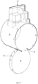
- FIG. 1 the back side 10 of a medium voltage control device 14 is illustrated.
- Electrical conductors 18, commonly known as busbars, are shown at the top and bottom of the back side 10 of a medium voltage control device 14 .
- One set of electrical conductors 18 are input conductors bringing power to the medium voltage control device and the other set of electrical conductors 18 are output conductors providing power to a load (not shown), which could be a single electrical device, a group of electrical devices, a particular section of a facility or other device(s) that consume electrical energy.
- a control device (not shown), which could be a circuit breaker, switch or other means of controlling the electrical energy being provided to the load.
- Each electrical conductor 18 is electrically connected to a primary electrical contact 54 (shown in Figure 2 ) by a mechanical fastener 22 , such as a bolt or similar threaded fastener.
- a boot 26 surrounds each of the electrical connections and a short section of the electrical conductor 18 adjacent the to the electrical connection.
- the boot 26 is made from a pliable electrically insulating material such as plastisol.
- the boot 26 is generally circular in shape and includes a side wall 30 and a cover 34 .
- the side wall 30 forms a tube-like structure which surrounds the electrical connection, mechanical fasteners 22 and immediately adjacent portions of the electrical conductors 18 .
- the cover 34 prevents unintentional contact with the electrical conductors 18 and mechanical fasteners 22 of the electrical connection when closed and permits direct access to the mechanical fasteners 22 when opened for periodic maintenance such as checking the torque of the mechanical fasteners 22 .
- the cover 34 is molded integrally with the side wall 30 forming a hinge 38 at their juncture. The cover 34 is permitted to rotate with respect to the side wall 30 between its closed position and its open position via the hinge 38 .
- the cover 34 defines an outwardly extending flange 42 around its perimeter which fits snugly in a circular opening 46 defined by the side wall 30 of the boot 26 .
- the cover 34 when in its closed and open positions, is approximately at 90 degrees with respect to the side wall 30 .
- the cover 34 is held in its closed position by any easily removable and replaceable means that can secure the cover flange 42 to the side wall 30 , such as wire ties 50 . It is to be understood that the means for holding the cover 34 in the closed position can include other methods that are part of the molding operation such as interlocking ribs and grooves.
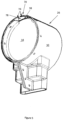
- the boot 26 and electrical connection are illustrated in cross-section.
- the electrical conductors 18 are electrically connected to a primary electrical contact 54 by the mechanical fasteners 22 .
- the primary electrical contact 54 is the electrical interface between the electrical conductors 18 and the electrical control devices located in a front part of the medium voltage control device 14 .
- the primary electrical contact 54 is secured to an electrically insulating bushing 58 .
- the boot 26 includes a securing means 62 which surrounds at least one of the electrical conductors 18 .
- the securing means 62 and boot side wall 30 which engages a portion of the insulating bushing 58 , hold the boot 26 in place around the electrical connection.
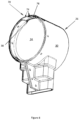
- the boot 26 is shown in more detail with the cover 34 closed and in the orientation for receiving electrical conductors 18 from above. If wire ties 50 are used to secure the cover flange 42 to the side wall 30 holes 66 can easily be punched in the cover flange 42 and side wall 3 0.
- the boot 26 is shown in more detail with the cover 34 open and in the orientation for receiving electrical conductors 18 from above.
- cover hold-open feature 70 is integrally molded in the side wall 30 of the boot.
- the cover hold-open feature 70 is a gate or pair of gates 74 , extending from one or both sides side of a gap 78 in the side wall 30 above the hinge 38. The cover 34 must be pushed past the gate(s) 74 to open position and pushed past the gate(s) 74 to close position.
- FIGS 5-7 illustrate generally triangular shaped gates 74 and figures 8-10 illustrate generally rectangular gates 74 . It is to be understood that the gate(s) 74 could have other shapes and still provide the function of the cover hold-open feature 70 .
Landscapes
- Engineering & Computer Science (AREA)
- Power Engineering (AREA)
- Physics & Mathematics (AREA)
- Electromagnetism (AREA)
- Connector Housings Or Holding Contact Members (AREA)
- Insulating Bodies (AREA)
- Casings For Electric Apparatus (AREA)
- Switch Cases, Indication, And Locking (AREA)
Claims (9)
- Elektrisch isolierte Tülle, die zum Umschließen einer elektrischen Verbindung zwischen zwei oder mehr elektrischen Leitern konfiguriert ist, umfassend:eine Tülle (26) mit einer Seitenwand (30), die eine Öffnung (46) zum Zugreifen auf die elektrische Verbindung definiert;eine Abdeckung (34), die an der Seitenwand (30) durch ein Scharnier (38) befestigt ist, so dass die Abdeckung (34) selektiv zwischen einer geschlossenen Position, die den Zugang zu den umschlossenen elektrischen Leitern verhindert, und einer offenen Position, die den Zugang zu den umschlossenen elektrischen Leitern ermöglicht, bewegt werden kann;ein Abdeckungssicherungsmittel, das verhindert, dass die Abdeckung (34) unbeabsichtigt von der geschlossenen Position in die offene Position bewegt wird;und ein Tüllensicherungsmittel (62) zum Verhindern, dass die Tülle (26) von den elektrischen Leitern entfernt wird, wobei die Tülle (26) und das Scharnier (38) aus einem biegsamen elektrisch isolierenden Material gebildet sind, und wobei das Scharnier (38) ein integraler Teil der Seitenwand (30) und der Abdeckung (34) ist, dadurch gekennzeichnet, dass ein Offenhaltemerkmal (70), das integral aus der Seitenwand (30) gebildet ist, konfiguriert ist, um die Abdeckung (34) in der offenen Position zu halten, wobei das Offenhaltemerkmal (70) ein Tor (74) ist, durch das das Scharnier (38) hindurchtreten muss, wenn die Abdeckung (34) von einer der offenen oder geschlossenen Positionen in die andere der offenen oder geschlossenen Positionen bewegt wird.
- Elektrisch isolierte Tülle nach Anspruch 1, wobei die Seitenwand (30) eine röhrenartige Struktur definiert, die konfiguriert ist, um die elektrische Verbindung der elektrischen Leiter zu umgeben.
- Elektrisch isolierte Tülle nach einem der Ansprüche 1 oder 2, wobei die Abdeckung (34) einen Flansch (42) umfasst, der sich um ihren Umfang nach außen erstreckt.
- Elektrisch isolierte Tülle nach Anspruch 3, wobei der Abdeckungsflansch (42) passgenau in die Öffnung (46) passt.
- Elektrisch isolierte Tülle nach Anspruch 3 oder 4, wobei das Abdeckungssicherungsmittel durch übereinstimmende Durchbrechungen in der Seitenwand (30) und dem Abdeckungsflansch (42) verläuft.
- Elektrisch isolierte Tülle nach einem der Ansprüche 1 - 5, wobei das Tüllensicherungsmittel (62) konfiguriert ist, um einen Abschnitt von mindestens einem der elektrischen Leiter zu umschließen.
- Elektrisch isolierte Tülle nach Anspruch 1, wobei die Form der Öffnung (46) und die Form der Abdeckung (34) identisch sind.
- Elektrisch isolierte Tülle nach Anspruch 7, wobei die Abdeckung (34) den Flansch (42) aufweist, der in die Seitenwand (30) eingreift, wenn die Abdeckung (34) geschlossen ist.
- Elektrisch isolierte Tülle nach einem der Ansprüche 7 oder 8, wobei das Sicherungsmittel ein Kabelbinder oder eine ähnliche Vorrichtung ist, die leicht eingebaut oder entfernt werden kann.
Applications Claiming Priority (1)
| Application Number | Priority Date | Filing Date | Title |
|---|---|---|---|
| US202063131514P | 2020-12-29 | 2020-12-29 |
Publications (3)
| Publication Number | Publication Date |
|---|---|
| EP4024632A1 EP4024632A1 (de) | 2022-07-06 |
| EP4024632C0 EP4024632C0 (de) | 2025-06-04 |
| EP4024632B1 true EP4024632B1 (de) | 2025-06-04 |
Family
ID=79164835
Family Applications (1)
| Application Number | Title | Priority Date | Filing Date |
|---|---|---|---|
| EP21217604.4A Active EP4024632B1 (de) | 2020-12-29 | 2021-12-23 | Elektrisch isolierte tülle zur verhinderung eines unbeabsichtigten kontakts mit stromführenden elektrischen leitern |
Country Status (3)
| Country | Link |
|---|---|
| US (1) | US12407150B2 (de) |
| EP (1) | EP4024632B1 (de) |
| CN (1) | CN114694988A (de) |
Citations (2)
| Publication number | Priority date | Publication date | Assignee | Title |
|---|---|---|---|---|
| US20070105442A1 (en) * | 2004-05-12 | 2007-05-10 | Fci | Plug connector and method for preassembly thereof |
| JP2013033604A (ja) * | 2011-08-01 | 2013-02-14 | Furukawa Electric Co Ltd:The | 端子カバー |
Family Cites Families (33)
| Publication number | Priority date | Publication date | Assignee | Title |
|---|---|---|---|---|
| US3278674A (en) * | 1964-06-12 | 1966-10-11 | Burndy Corp | Connector insulating housing |
| US3812279A (en) * | 1973-02-12 | 1974-05-21 | H Voegeli | Cable television housing with lockably joined cover and base |
| US4063110A (en) * | 1976-01-12 | 1977-12-13 | Glick Michael B | Security device |
| US4138187A (en) * | 1977-12-12 | 1979-02-06 | Harvey Hubbell, Incorporated | Lift cover assembly for electrical wiring device |
| US4593541A (en) * | 1984-05-07 | 1986-06-10 | Nathaniel Hollis | Locking electrical outlet box |
| US4712861A (en) * | 1985-02-07 | 1987-12-15 | Northern Telecom Limited | Two-channel hermaphroditic fiber connector |
| US4676569A (en) * | 1985-11-20 | 1987-06-30 | Lambert Harry S | Protective cover for cable television distribution taps |
| US4707043A (en) * | 1986-11-03 | 1987-11-17 | Reed Charlie C | Electrical connector |
| US4850014A (en) * | 1987-03-10 | 1989-07-18 | Communications Systems, Inc. | Multiple dwelling interface box |
| US4749359A (en) * | 1987-08-27 | 1988-06-07 | Siecor Corporation | Security override network interface device |
| US4957446A (en) * | 1989-12-11 | 1990-09-18 | Belsky Ronald R | Lockout device for electrically operated equipment and devices |
| US5052939A (en) * | 1990-02-02 | 1991-10-01 | Koch William C | Utility protector |
| US5190475A (en) * | 1992-02-05 | 1993-03-02 | E. I. Du Pont De Nemours And Company | Electrically insulative connector boots |
| US5288239A (en) * | 1992-11-12 | 1994-02-22 | Johnson Jack L | Device for preventing the theft of electrical appliances |
| DE9315054U1 (de) * | 1993-10-05 | 1993-12-16 | Seewald, Gerhard, 90542 Eckental | Bewegliche Steckdose |
| US5645449A (en) * | 1995-02-21 | 1997-07-08 | The Whitaker Corporation | Low profile mixed media information outlet |
| ES2182158T3 (es) * | 1995-12-19 | 2003-03-01 | Fresenius Ag | Un sistema de comunicacion, por ejemplo para aplicaciones biomedicas. |
| ATE231971T1 (de) * | 1996-09-27 | 2003-02-15 | Inverness Medical Switzerland | Test-kit und vorrichtungen |
| WO1998053531A1 (en) * | 1997-05-22 | 1998-11-26 | Thomas & Betts International, Inc. | Cable splice closure |
| US6007353A (en) * | 1998-04-22 | 1999-12-28 | Webster; Stephen L. | Electrical connector enclosure |
| US7717740B2 (en) * | 2004-12-30 | 2010-05-18 | Thomas & Betts International, Inc. | Electrical connector including viewing window assembly and associated methods |
| US7094094B2 (en) * | 2004-12-30 | 2006-08-22 | Homac Mfg Company | Electrical connector including insulating boots and associated methods |
| KR100868255B1 (ko) * | 2005-04-19 | 2008-11-11 | 주식회사 엘지화학 | 단자 연결장치 |
| US7450368B2 (en) * | 2006-09-08 | 2008-11-11 | Eaton Corporation | Front access electrical enclosure and electrical bus assembly therefor |
| US7440260B2 (en) * | 2006-09-08 | 2008-10-21 | Eaton Corporation | Electrical bus member mounting system and electrical enclosure employing the same |
| US9935442B2 (en) * | 2011-07-26 | 2018-04-03 | Kolex PTY LTD. | Weather resistant power outlets |
| KR20130133634A (ko) * | 2012-05-29 | 2013-12-09 | 최영수 | 배선용 체결부재의 절연커버 |
| US9509097B2 (en) * | 2014-09-27 | 2016-11-29 | Albert E. Peckham | Safety electrical outlet arrangement |
| GB2546106B (en) * | 2016-01-11 | 2019-11-06 | Ford Global Tech Llc | Improvements in or relating to chargeports |
| US10559945B1 (en) * | 2018-08-30 | 2020-02-11 | Siemens Industy, Inc. | Insulative boots and power distribution assemblies |
| US12034244B2 (en) * | 2019-01-29 | 2024-07-09 | Brady Worldwide, Inc. | Battery connector lockout device |
| JP2020140817A (ja) * | 2019-02-27 | 2020-09-03 | 住友電装株式会社 | コネクタ |
| US11121503B1 (en) * | 2020-07-15 | 2021-09-14 | Kinsun Industries Inc. | Quickly assembled cable connector |
-
2021
- 2021-12-23 EP EP21217604.4A patent/EP4024632B1/de active Active
- 2021-12-27 US US17/562,292 patent/US12407150B2/en active Active
- 2021-12-29 CN CN202111637632.5A patent/CN114694988A/zh active Pending
Patent Citations (2)
| Publication number | Priority date | Publication date | Assignee | Title |
|---|---|---|---|---|
| US20070105442A1 (en) * | 2004-05-12 | 2007-05-10 | Fci | Plug connector and method for preassembly thereof |
| JP2013033604A (ja) * | 2011-08-01 | 2013-02-14 | Furukawa Electric Co Ltd:The | 端子カバー |
Also Published As
| Publication number | Publication date |
|---|---|
| EP4024632C0 (de) | 2025-06-04 |
| US20220209512A1 (en) | 2022-06-30 |
| CN114694988A (zh) | 2022-07-01 |
| EP4024632A1 (de) | 2022-07-06 |
| US12407150B2 (en) | 2025-09-02 |
Similar Documents
| Publication | Publication Date | Title |
|---|---|---|
| US4079439A (en) | Loadcenter having a dual purpose neutral rail | |
| US4389021A (en) | Panel mounted connector for use in confined areas | |
| US9515462B2 (en) | Shutter device for an electrical switchgear panel, and related switchgear panel | |
| US11638358B2 (en) | High-voltage device | |
| EP0677214B1 (de) | Kabelkanalabdeckung | |
| EP4024632B1 (de) | Elektrisch isolierte tülle zur verhinderung eines unbeabsichtigten kontakts mit stromführenden elektrischen leitern | |
| KR910016118A (ko) | 전면방호 터미네이터 및 전면무방호 터미네이터와 조합한 개폐장치 | |
| US2888529A (en) | Interlock means for bus duct plug-in units | |
| US9667041B2 (en) | Electrically insulating cover for terminal assembly | |
| DE102011082191B4 (de) | Isolationsvorrichtung, Schutzschaltgerät und Sammelschienen-verbund | |
| KR102034893B1 (ko) | 배전반 | |
| EP2667394B1 (de) | Mehrpoliger Schalter und/oder Trennschalter für Niederspannung | |
| US7262519B1 (en) | Actuator unit with at least two actuators and a secure control unit | |
| KR100746787B1 (ko) | 안전 잠금 장치를 구비한 분전함 | |
| EP3930125B1 (de) | Polkomponente und schutzschalter damit | |
| KR102166906B1 (ko) | 링메인유닛 | |
| US12119633B2 (en) | Tap off box | |
| JP2007533083A (ja) | 開閉機器 | |
| KR101830843B1 (ko) | 수배전반의 전력용 퓨즈 | |
| US9812241B2 (en) | Transformer security enclosure | |
| US3436602A (en) | Electric wiring device comprising automatic switch and socket | |
| KR102267102B1 (ko) | 다중 접속 구조의 개폐기기 | |
| KR20170003079U (ko) | 소형 배선용 차단기 | |
| CN218299729U (zh) | 一种断路器 | |
| EP4708334A2 (de) | Schutzanordnungen für wildtiere und verfahren zur verwendung davon |
Legal Events
| Date | Code | Title | Description |
|---|---|---|---|
| PUAI | Public reference made under article 153(3) epc to a published international application that has entered the european phase |
Free format text: ORIGINAL CODE: 0009012 |
|
| STAA | Information on the status of an ep patent application or granted ep patent |
Free format text: STATUS: THE APPLICATION HAS BEEN PUBLISHED |
|
| AK | Designated contracting states |
Kind code of ref document: A1 Designated state(s): AL AT BE BG CH CY CZ DE DK EE ES FI FR GB GR HR HU IE IS IT LI LT LU LV MC MK MT NL NO PL PT RO RS SE SI SK SM TR |
|
| STAA | Information on the status of an ep patent application or granted ep patent |
Free format text: STATUS: REQUEST FOR EXAMINATION WAS MADE |
|
| 17P | Request for examination filed |
Effective date: 20230105 |
|
| RBV | Designated contracting states (corrected) |
Designated state(s): AL AT BE BG CH CY CZ DE DK EE ES FI FR GB GR HR HU IE IS IT LI LT LU LV MC MK MT NL NO PL PT RO RS SE SI SK SM TR |
|
| STAA | Information on the status of an ep patent application or granted ep patent |
Free format text: STATUS: EXAMINATION IS IN PROGRESS |
|
| GRAP | Despatch of communication of intention to grant a patent |
Free format text: ORIGINAL CODE: EPIDOSNIGR1 |
|
| STAA | Information on the status of an ep patent application or granted ep patent |
Free format text: STATUS: GRANT OF PATENT IS INTENDED |
|
| 17Q | First examination report despatched |
Effective date: 20241206 |
|
| RIC1 | Information provided on ipc code assigned before grant |
Ipc: H02B 1/20 20060101ALN20241211BHEP Ipc: H01R 13/447 20060101ALN20241211BHEP Ipc: H01R 9/18 20060101ALN20241211BHEP Ipc: H01R 4/70 20060101ALN20241211BHEP Ipc: H02B 11/02 20060101ALN20241211BHEP Ipc: H02G 5/02 20060101ALI20241211BHEP Ipc: H01B 17/58 20060101ALI20241211BHEP Ipc: H02B 1/14 20060101ALI20241211BHEP Ipc: H02B 1/06 20060101AFI20241211BHEP |
|
| INTG | Intention to grant announced |
Effective date: 20250103 |
|
| GRAS | Grant fee paid |
Free format text: ORIGINAL CODE: EPIDOSNIGR3 |
|
| GRAA | (expected) grant |
Free format text: ORIGINAL CODE: 0009210 |
|
| STAA | Information on the status of an ep patent application or granted ep patent |
Free format text: STATUS: THE PATENT HAS BEEN GRANTED |
|
| AK | Designated contracting states |
Kind code of ref document: B1 Designated state(s): AL AT BE BG CH CY CZ DE DK EE ES FI FR GB GR HR HU IE IS IT LI LT LU LV MC MK MT NL NO PL PT RO RS SE SI SK SM TR |
|
| REG | Reference to a national code |
Ref country code: GB Ref legal event code: FG4D |
|
| REG | Reference to a national code |
Ref country code: CH Ref legal event code: EP |
|
| REG | Reference to a national code |
Ref country code: IE Ref legal event code: FG4D |
|
| U01 | Request for unitary effect filed |
Effective date: 20250604 |
|
| U07 | Unitary effect registered |
Designated state(s): AT BE BG DE DK EE FI FR IT LT LU LV MT NL PT RO SE SI Effective date: 20250611 |
|
| PG25 | Lapsed in a contracting state [announced via postgrant information from national office to epo] |
Ref country code: ES Free format text: LAPSE BECAUSE OF FAILURE TO SUBMIT A TRANSLATION OF THE DESCRIPTION OR TO PAY THE FEE WITHIN THE PRESCRIBED TIME-LIMIT Effective date: 20250604 |
|
| PG25 | Lapsed in a contracting state [announced via postgrant information from national office to epo] |
Ref country code: NO Free format text: LAPSE BECAUSE OF FAILURE TO SUBMIT A TRANSLATION OF THE DESCRIPTION OR TO PAY THE FEE WITHIN THE PRESCRIBED TIME-LIMIT Effective date: 20250904 Ref country code: GR Free format text: LAPSE BECAUSE OF FAILURE TO SUBMIT A TRANSLATION OF THE DESCRIPTION OR TO PAY THE FEE WITHIN THE PRESCRIBED TIME-LIMIT Effective date: 20250905 |
|
| PG25 | Lapsed in a contracting state [announced via postgrant information from national office to epo] |
Ref country code: PL Free format text: LAPSE BECAUSE OF FAILURE TO SUBMIT A TRANSLATION OF THE DESCRIPTION OR TO PAY THE FEE WITHIN THE PRESCRIBED TIME-LIMIT Effective date: 20250604 |
|
| PG25 | Lapsed in a contracting state [announced via postgrant information from national office to epo] |
Ref country code: HR Free format text: LAPSE BECAUSE OF FAILURE TO SUBMIT A TRANSLATION OF THE DESCRIPTION OR TO PAY THE FEE WITHIN THE PRESCRIBED TIME-LIMIT Effective date: 20250604 |
|
| PG25 | Lapsed in a contracting state [announced via postgrant information from national office to epo] |
Ref country code: RS Free format text: LAPSE BECAUSE OF FAILURE TO SUBMIT A TRANSLATION OF THE DESCRIPTION OR TO PAY THE FEE WITHIN THE PRESCRIBED TIME-LIMIT Effective date: 20250904 |
|
| PG25 | Lapsed in a contracting state [announced via postgrant information from national office to epo] |
Ref country code: IS Free format text: LAPSE BECAUSE OF FAILURE TO SUBMIT A TRANSLATION OF THE DESCRIPTION OR TO PAY THE FEE WITHIN THE PRESCRIBED TIME-LIMIT Effective date: 20251004 |
|
| PGFP | Annual fee paid to national office [announced via postgrant information from national office to epo] |
Ref country code: GB Payment date: 20251223 Year of fee payment: 5 |
|
| PG25 | Lapsed in a contracting state [announced via postgrant information from national office to epo] |
Ref country code: SM Free format text: LAPSE BECAUSE OF FAILURE TO SUBMIT A TRANSLATION OF THE DESCRIPTION OR TO PAY THE FEE WITHIN THE PRESCRIBED TIME-LIMIT Effective date: 20250604 |
|
| PG25 | Lapsed in a contracting state [announced via postgrant information from national office to epo] |
Ref country code: CZ Free format text: LAPSE BECAUSE OF FAILURE TO SUBMIT A TRANSLATION OF THE DESCRIPTION OR TO PAY THE FEE WITHIN THE PRESCRIBED TIME-LIMIT Effective date: 20250604 |
|
| PG25 | Lapsed in a contracting state [announced via postgrant information from national office to epo] |
Ref country code: SK Free format text: LAPSE BECAUSE OF FAILURE TO SUBMIT A TRANSLATION OF THE DESCRIPTION OR TO PAY THE FEE WITHIN THE PRESCRIBED TIME-LIMIT Effective date: 20250604 |
|
| U20 | Renewal fee for the european patent with unitary effect paid |
Year of fee payment: 5 Effective date: 20251223 |