EP4024000B1 - Apparatus for automatically cleaning heat exchanger bundle - Google Patents
Apparatus for automatically cleaning heat exchanger bundle Download PDFInfo
- Publication number
- EP4024000B1 EP4024000B1 EP19916543.2A EP19916543A EP4024000B1 EP 4024000 B1 EP4024000 B1 EP 4024000B1 EP 19916543 A EP19916543 A EP 19916543A EP 4024000 B1 EP4024000 B1 EP 4024000B1
- Authority
- EP
- European Patent Office
- Prior art keywords
- heat exchanger
- bundle
- washing
- module
- exchanger bundle
- Prior art date
- Legal status (The legal status is an assumption and is not a legal conclusion. Google has not performed a legal analysis and makes no representation as to the accuracy of the status listed.)
- Active
Links
Images




Classifications
-
- F—MECHANICAL ENGINEERING; LIGHTING; HEATING; WEAPONS; BLASTING
- F28—HEAT EXCHANGE IN GENERAL
- F28G—CLEANING OF INTERNAL OR EXTERNAL SURFACES OF HEAT-EXCHANGE OR HEAT-TRANSFER CONDUITS, e.g. WATER TUBES OR BOILERS
- F28G1/00—Non-rotary, e.g. reciprocated, appliances
- F28G1/16—Non-rotary, e.g. reciprocated, appliances using jets of fluid for removing debris
- F28G1/163—Non-rotary, e.g. reciprocated, appliances using jets of fluid for removing debris from internal surfaces of heat exchange conduits
-
- F—MECHANICAL ENGINEERING; LIGHTING; HEATING; WEAPONS; BLASTING
- F28—HEAT EXCHANGE IN GENERAL
- F28G—CLEANING OF INTERNAL OR EXTERNAL SURFACES OF HEAT-EXCHANGE OR HEAT-TRANSFER CONDUITS, e.g. WATER TUBES OR BOILERS
- F28G3/00—Rotary appliances
- F28G3/16—Rotary appliances using jets of fluid for removing debris
- F28G3/163—Rotary appliances using jets of fluid for removing debris from internal surfaces of heat exchange conduits
-
- F—MECHANICAL ENGINEERING; LIGHTING; HEATING; WEAPONS; BLASTING
- F28—HEAT EXCHANGE IN GENERAL
- F28G—CLEANING OF INTERNAL OR EXTERNAL SURFACES OF HEAT-EXCHANGE OR HEAT-TRANSFER CONDUITS, e.g. WATER TUBES OR BOILERS
- F28G15/00—Details
- F28G15/003—Control arrangements
-
- F—MECHANICAL ENGINEERING; LIGHTING; HEATING; WEAPONS; BLASTING
- F28—HEAT EXCHANGE IN GENERAL
- F28G—CLEANING OF INTERNAL OR EXTERNAL SURFACES OF HEAT-EXCHANGE OR HEAT-TRANSFER CONDUITS, e.g. WATER TUBES OR BOILERS
- F28G15/00—Details
- F28G15/02—Supports for cleaning appliances, e.g. frames
-
- F—MECHANICAL ENGINEERING; LIGHTING; HEATING; WEAPONS; BLASTING
- F28—HEAT EXCHANGE IN GENERAL
- F28G—CLEANING OF INTERNAL OR EXTERNAL SURFACES OF HEAT-EXCHANGE OR HEAT-TRANSFER CONDUITS, e.g. WATER TUBES OR BOILERS
- F28G15/00—Details
- F28G15/08—Locating position of cleaning appliances within conduits
-
- F—MECHANICAL ENGINEERING; LIGHTING; HEATING; WEAPONS; BLASTING
- F28—HEAT EXCHANGE IN GENERAL
- F28G—CLEANING OF INTERNAL OR EXTERNAL SURFACES OF HEAT-EXCHANGE OR HEAT-TRANSFER CONDUITS, e.g. WATER TUBES OR BOILERS
- F28G9/00—Cleaning by flushing or washing, e.g. with chemical solvents
-
- F—MECHANICAL ENGINEERING; LIGHTING; HEATING; WEAPONS; BLASTING
- F28—HEAT EXCHANGE IN GENERAL
- F28G—CLEANING OF INTERNAL OR EXTERNAL SURFACES OF HEAT-EXCHANGE OR HEAT-TRANSFER CONDUITS, e.g. WATER TUBES OR BOILERS
- F28G15/00—Details
- F28G2015/006—Arrangements for processing a cleaning fluid after use, e.g. filtering and recycling
Definitions
- the present invention relates to an automatic washing apparatus for a heat exchanger bundle and, more particularly, to an automatic washing apparatus for a heat exchanger bundle, the automatic washing apparatus being able to automatically recognize tens of tubes of a heat exchanger bundle and automatically wash the tubes in accordance with a program.
- a heat exchanger is used as a condenser in some cases to decrease the temperature of a turbine lubricant using cooling water that circulates in a turbine lubricant cooler or to keep food fresh at a low temperature without spoiling in a refrigerator that is used at home.
- An air spray type washing apparatus is a device that washes a tube of a heat exchanger by putting a tube of a cooler in a container fully filled with a detergent, generating bubbles and making the detergent flow using the density difference between the bubbles and the detergent.
- Prior patent document US9863727B1 discloses an automatic washing apparatus for a heat exchanger bundle according to the preamble of claim 1 and describes a mobile multi-function hydro-blast cleaning and tube lancing apparatus and system.
- Prior patent document KR1020120133356A describes an automated pipe welding and expanding apparatus.
- Prior patent document US20170364096A1 describes a system and method for cleaning of heat exchanger tubes.
- Prior patent document US6681839B1 describes a heat exchanger exchange-tube cleaning lance positioning system.
- an objective of the present invention is to provide an automatic washing apparatus for a heat exchanger bundle, the automatic washing apparatus being able to quickly wash the inside of a tube by accurately recognizing the position of a heat exchanger bundle tube and set coordinates on a map.
- Another objective of the present invention is to provide an automatic washing apparatus for a heat exchanger bundle, the automatic washing apparatus being able to automatically wash an external bundle and an internal tube of a heat exchanger using a control module in accordance with set operation patterns of an external washing module and an internal washing module.
- Another objective of the present invention is to provide an automatic washing apparatus for a heat exchanger bundle, the automatic washing apparatus being able to rotate a heat exchanger bundle while adjusting a gap for supporting the bottom of the heat exchanger bundle regardless of the length of a heat exchanger.
- Another objective of the present invention is to provide an automatic washing apparatus for a heat exchanger bundle, the automatic washing apparatus in which a nozzle feeder of an internal washing module is inserted into or taken out of a tube at an accurate position by automatically recognizing the position of the heat exchanger tube.
- Another objective of the present invention is to provide an automatic washing apparatus for a heat exchanger bundle, the automatic washing apparatus being able to reuse the washing water used for washing a heat exchanger by reprocessing the washing water.
- the automatic washing apparatus for a heat exchanger of the present invention since tubes of a heat exchanger bundle are recognized through a camera and the inside of the tubes of the heat exchanger bundle are automatically washed by a program that designates coordinates on the basis of a map, whereby quick and accurate washing is possible.
- washing water used for washing a heat exchanger Since it is possible to reuse washing water used for washing a heat exchanger as washing water by reprocessing the washing water, there is an effect that eco-friendly work is possible and the cost is reduced.
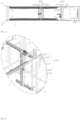
- FIG. 1 is a perspective view of an automatic washing apparatus for a heat exchanger bundle according to an embodiment of the present invention
- FIG. 2 is a side view of FIG. 1
- FIG. 3 is a plan view of FIG. 1 .
- an automatic washing apparatus for a heat exchanger bundle fundamentally includes a chamber 100, an internal washing module 200, a camera 300, and a control module 400, and may further include an external washing module 500, a bundle rotation module 600, and a waste water processing unit (not shown).
- the chamber 100 is a structure that can accommodate a heat exchanger bundle 1 therein.
- the internal washing module 200, the camera 300, and the control module 400 may be installed in the chamber 100 to wash the heat exchanger bundle 1 disposed in the chamber 100. Further, a frame 120 is installed in the chamber 120 and the internal washing module 200 can be hung on the frame 120.
- the chamber 100 has a long hexahedron shape, keeps the heat exchanger bundle 1, and provides an internal darkroom, so photographing by the camera 300 can be smoothly performed and it is possible to prevent washed contaminants from be sprayed outside in washing.
- one side and the top of the chamber 100 may be open so that a worker can check a washing process. Further, one side of the chamber 100 may be opened and closed so that it is possible to put and wash the heat exchanger bundle 1 in the chamber 100 and take the heat exchanger bundle 1 out of the chamber 100 after finishing washing.
- guide rails 601 may be installed on the floor inside the chamber 100 so that the heat exchanger bundle 1 can be smoothly moved by the bundle rotation module 600.
- the internal washing module 200 is a part for washing the insides of tubes 2 of the heat exchanger bundle 1.
- the internal washing module 200 is disposed on the frame 120 in the chamber 100.
- the internal washing module 200 is laterally moved by a motor and sprays washing water into the tubes 2 of the heat exchanger bundle 1.
- the internal washing module 200 includes an internal washer 210, a nozzle feeder actuator 220 ( FIG. 3 ), a tube Y-axis actuator 230, and a tube Z-axis actuator 240.
- the internal washer 210 has a nozzle feeder that sprays washing water into the tubes 2 of the heat exchanger bundle 1 and is moved by the nozzle feeder actuator 220 ( FIG. 3 ), the tube Y-axis actuator 230, and the tube Z-axis actuator 240
- the nozzle feeder actuator 220 ( FIG. 3 ) can move the internal washer 210 in the X-axial direction, so it inserts or takes the nozzle feeder into or out of the tube 2 of the heat exchanger bundle 1.
- the tube Y-axis actuator 230 moves the internal washer 210 left and right with respect to the bundle 210.
- the tube Y-axis actuator 230 has an extension shaft 250 that is operated by rotation of a motor and gears are disposed at the upper end and the lower end of the extension shaft and can rotate in mesh with rails on an upper frame and a lower frame.
- the tube Z-axis actuator 240 moves the internal washer 210 up and down with respect to the bundle.
- the internal washing module 200 further includes rails, driving wheels, and rollers to be able to axially move, but these components are not described.
- the camera 300 is a part that photographs the tubes of the heat exchanger bundle.
- the camera 300 is installed in the chamber 100 and can photograph the tubes 2 of the heat exchanger bundle 1 under the darkroom condition of the chamber 100, whereby it is possible to check the number of the tubes 2.
- a separate light 310 may be installed at the upper, lower, and rear portions of the camera 300. It is possible to check the number and shape of tubes 2 by taking pictures of the tubes 2 of the heat exchanger bundle 1 using the camera 300.
- the control module 400 is a part that controls washing of the heat exchanger bundle.
- the control module 400 may be composed of a computer 410 and a PLC 420.
- the computer 410 is connected with the camera 300, receives an image of the tubes 2 of the heat exchanger bundle 1, makes a map by setting coordinates of each of the tubes 2 of the heat exchanger bundle 1, and transmits the coordinates to the PLC 420.
- the computer 410 can increase the recognition rate of the insides of the tubes 2 of the heat exchanger bundle 1, that is, holes, using deep learning software, and has a function of keeping a map. When there is an error in recognition of a hole, a worker can perform adding or removing.
- the computer 410 can recognize the insides of the tubes as holes from the image of the tubes 2 of the heat exchanger bundle 1 transmitted from the camera 300, digitize the diameters of the holes and the distances between the holes, and show a hole as an error when the diameter of the hole is out of a predetermined tolerance range from an average value or is out of a predetermined tolerance range from an average value of the distance of the hole. A worker can correct the error.
- the PLC 420 controls the operation of the internal washing module 200 in the Y-axial and Z-axial directions in accordance with the coordinates on the basis of the map, whereby it is possible to sequentially wash the insides of the tubes 2 of the heat exchanger bundle 1.
- the number of nozzle feeders of the internal washing module 200 is selectively programmed in a control module, so a tube is washed on the basis of the number of nozzle feeders and it is required to prevent repeated washing.
- the movement distance of the external washing module 500 is checked by an encoder installed in each module, and when there is an error in the movement distance, position correction is performed to further move the external washing module 500 by the error.
- the external washing module 500 is disposed at front and rear portions of the frame 110 to wash the outside of the heat exchanger bundle 1.
- the external washing module 500 can be axially moved by a motor and can wash the outside of the heat exchanger bundle by spraying washing water.
- the external washing module 500 includes an external washer 510, a bundle X-axis actuator 520, a bundle Y-axis actuator 530, and a bundle Z-axis actuator 540.
- the external washer 510 has a nozzle head 511 for spraying washing water to the outer side of the heat exchanger bundle 1 and is moved by the bundle X-axis actuator 520, the bundle Y-axis actuator 530, and the bundle Z-axis actuator 540.
- the bundle X-axis actuator 520 moves the external washer 510 in the longitudinal direction of the heat exchanger bundle.
- the bundle Y-axis actuator 530 moves the external washer 510 left and right with respect to the heat exchanger bundle.
- the bundle Z-axis actuator 540 moves the external washer 510 up and down with respect to the heat exchanger bundle.
- the external washing module 500 further includes rails, driving wheels, and rollers to be able to axially move.
- the rails are disposed in the X-axial, Y-axial, and Z-axial directions and have a plurality of movement guide holes longitudinally formed with predetermined gaps on a side.
- the driving wheels are formed in gear shapes, are rotated by a motor, and are axially moved while teeth are sequentially inserted into the movement guide holes of the rails.
- the rollers are symmetrically disposed on a side and the other side of each of the rails and enables smooth movement by distributing load that is applied to the driving wheels.
- the bundle rotation modules 600 are disposed at both sides under the frame 110, are operated to be able to support and rotate the heat exchanger bundle, and move a heat exchanger into or out of the chamber 110 along the guide rails 601.
- the bundle rotation module 600 includes bundle rotors 610, connection brackets 620, and bundle movers 630.
- the bundle rotors 610 are formed in roller shapes, are symmetrically disposed front and back in the longitudinal direction of the bundle, and can support and rotate the bundle.
- a motor 50 and a reducer 640 are connected to the rotors 610 and can be driven by the control module.
- the bundle rotors 610 may be disposed at both ends of the heat exchanger bundle, and may be additionally disposed at the center of a bundle, depending on the length of a heat exchanger, thereby being able to make rotation smooth.
- connection brackets 620 are formed in rectangular frame shapes and are coupled to the bottom of a pair of bundle rotors 610, thereby connecting the bundle rotors 610.
- the connection brackets 620 may have a structure that can support the weight of a heat exchanger bundle.
- the bundle movers 630 are disposed at the both front and rear lower ends of the connection brackets 620 to correspond to the positions of the pair of bundle rotors 610, and the positions of the bundle movers 630 can be adjusted in accordance with the length of a heat exchanger bundle.
- control module 400 controls the operations of the internal washing module 200, the external washing module 500, and the bundle rotation module 600 in accordance with set operation patterns.
- the control module 400 may be composed of an electric controller, a PLC electronic controller, and a pneumatic circuit.
- a work result is shown in an output panel 450, so a worker can easily check the work result.
- a worker inputs an external washing pattern mode 441 and an internal washing pattern mode 442 through an input panel 440 of the control module 400, whereby the operations of the internal washing module 200, the external washing module 500, and the bundle rotation module 600 can be set in advance.
- the operation pattern of the external washing module 500 is set in accordance with the washing position and washing order of a heat exchanger bundle.
- the control module 400 enables the entire surface of a bundle to be uniformly washed by rotating the bundle with predetermined intervals by driving the bundle rotation module 600 in accordance with the external washing pattern mode 441 when washing a heat exchanger bundle.
- the operation pattern of the internal washing module 200 is set in accordance with the washing positions and washing order of the tubes on the basis of coordinates received from the computer of the control module 400.
- a map is made by recognizing the position of a tube through the camera and setting coordinates through the computer, whereby the internal washer of the internal washing module 200 can be automatically driven by PLC setting.
- the operations of the internal washing module 200, the external washing module 500, and the bundle rotation module 600 are automatically controlled in accordance with the external washing pattern mode 441 and the internal washing pattern mode 442 set in the control module 400, whereby it is possible to wash a large amount of heat exchange within a short time and it is possible to accurately and completely wash set points.
- the waste water processing unit 700 which filters washing water used in the internal washing pattern mode 442 and the external washing pattern mode 441 to reuse the wash in water, includes a water collection tank, a water separator 720, a filter 730, a washing blower 740, a backwash tank 750, and a processing tank 760.
- the water collection tank collects washing water used by the internal washing module 200 and the external washing module 500 and supplies the washing water to the water separator 720.
- the water separator 720 receives washing water from the water collection tank and separates the washing water into water and oil, has a structure in which a plurality of plates having egg plate shapes are stacked, thereby being able to separate washing water into water and oil within a short time.
- the filter 730 which filters out foreign substances from the water separated by the water separator 720, has a plurality of stacked fiber filters, thereby being able to secure a large filtering area.
- the washing blower 740 is disposed at the inlet of the filter 730 and increases the flow rate of washing water.
- the backwash tank 750 is connected to the filter 730 to wash out the filtered floating particles.
- the processing tank 760 is disposed at the outlet of the filter 730 to supply the filtered washing water back to the internal washing module 200 and the external washing module 500.
- the fundamental concept of the present invention is to provide an automatic washing apparatus for a heat exchanger, the automatic washing apparatus being able to automatically wash the outside of a heat exchanger bundle and the inside of a tube in accordance with the set operation patterns of an internal washing module and an external washing module and being able to reuse washing water used for washing a heat exchanger as washing water by reprocessing the washing water.
Landscapes
- Engineering & Computer Science (AREA)
- Chemical & Material Sciences (AREA)
- Combustion & Propulsion (AREA)
- Mechanical Engineering (AREA)
- General Engineering & Computer Science (AREA)
- Cleaning By Liquid Or Steam (AREA)
Description
- The present invention relates to an automatic washing apparatus for a heat exchanger bundle and, more particularly, to an automatic washing apparatus for a heat exchanger bundle, the automatic washing apparatus being able to automatically recognize tens of tubes of a heat exchanger bundle and automatically wash the tubes in accordance with a program.
- A heat exchanger is used as a condenser in some cases to decrease the temperature of a turbine lubricant using cooling water that circulates in a turbine lubricant cooler or to keep food fresh at a low temperature without spoiling in a refrigerator that is used at home.
- In order to wash such heat exchangers, a worker washed bundles and tubes by manually spraying washing water using compressed air or performed washing using an air spray type washing apparatus. An air spray type washing apparatus is a device that washes a tube of a heat exchanger by putting a tube of a cooler in a container fully filled with a detergent, generating bubbles and making the detergent flow using the density difference between the bubbles and the detergent.
- When a worker manually washes a tube of a heat exchanger, there is a problem that the worker has difficulty in washing due to fine dust produced when a detergent is sprayed, and it takes long time to completely wash the tube.
- Further, when washing a heat exchanger using an air spray type washing apparatus, it is required to fill up a container with a detergent and it is required to additionally inject a detergent into the container because the detergent is evaporated by production of bubbles, so there is a problem that too much detergent is consumed. Further, since only the portions that the detergent comes in contact due to bubbles are washed, uniform washing is difficult.
- In order to solve this problem, an apparatus for washing a tube bundle of a cooler has been disclosed in
Korean Utility Model Registration No. 20-0476774 US9863727B1 claim 1 and describes a mobile multi-function hydro-blast cleaning and tube lancing apparatus and system. Prior patent documentKR1020120133356A US20170364096A1 describes a system and method for cleaning of heat exchanger tubes. Prior patent documentUS6681839B1 describes a heat exchanger exchange-tube cleaning lance positioning system. - Accordingly, in order to solve the problems of the related art, an objective of the present invention is to provide an automatic washing apparatus for a heat exchanger bundle, the automatic washing apparatus being able to quickly wash the inside of a tube by accurately recognizing the position of a heat exchanger bundle tube and set coordinates on a map.
- Another objective of the present invention is to provide an automatic washing apparatus for a heat exchanger bundle, the automatic washing apparatus being able to automatically wash an external bundle and an internal tube of a heat exchanger using a control module in accordance with set operation patterns of an external washing module and an internal washing module.
- Another objective of the present invention is to provide an automatic washing apparatus for a heat exchanger bundle, the automatic washing apparatus being able to rotate a heat exchanger bundle while adjusting a gap for supporting the bottom of the heat exchanger bundle regardless of the length of a heat exchanger.
- Another objective of the present invention is to provide an automatic washing apparatus for a heat exchanger bundle, the automatic washing apparatus in which a nozzle feeder of an internal washing module is inserted into or taken out of a tube at an accurate position by automatically recognizing the position of the heat exchanger tube.
- Another objective of the present invention is to provide an automatic washing apparatus for a heat exchanger bundle, the automatic washing apparatus being able to reuse the washing water used for washing a heat exchanger by reprocessing the washing water.
- The invention is defined in the appended claims. In order to achieve the objectives, an automatic washing apparatus for a heat exchanger bundle according to
claim 1 is provided. Further advantageous embodiments of the invention are defined in claims 2-8. - According to the automatic washing apparatus for a heat exchanger of the present invention, since tubes of a heat exchanger bundle are recognized through a camera and the inside of the tubes of the heat exchanger bundle are automatically washed by a program that designates coordinates on the basis of a map, whereby quick and accurate washing is possible.
- It is possible to automatically wash an external bundle and internal tubes of a heat exchanger by driving an external washing module and an internal washing module in accordance with a washing position and a washing order set by a worker.
- Since it is possible to adjust the gaps of bundle rotation modules that support a heat exchanger bundle, it is possible to heat exchanger bundles having various lengths.
- It is possible to wash the entire surface of a heat exchanger bundle by automatically rotating the heat exchanger bundle and a worker can visually check a position not sufficiently washed or a position that needs to be washed.
- Since the positions of heat exchanger tubes are automatically recognized and nozzle feeders of the internal washing module are inserted into or taken out of tubes at accurate positions, work time can be reduced and work cost can be decreased by automation.
- Since it is possible to reuse washing water used for washing a heat exchanger as washing water by reprocessing the washing water, there is an effect that eco-friendly work is possible and the cost is reduced.
-
-
FIG. 1 is a perspective view of an automatic washing apparatus for a heat exchanger bundle according to an embodiment of the present invention; -
FIG. 2 is a side view ofFIG. 1 ; -
FIG. 3 is a plan view ofFIG. 1 ; -
FIG. 4 is a partially enlarged view of the portion C ofFIG. 1 ; -
FIG. 5 is a cross-sectional view showing a side of the cross-section A-A ofFIG. 2 ; -
FIG. 6 is a partial enlarged view of the portion D ofFIG. 1 ; -
FIG. 7 is a view showing the configuration of a bundle rotation module according to an embodiment of the present invention; -
FIG. 8 is a view showing a process of processing washing water according to an embodiment of the present invention; -
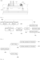
FIG. 9 is a block diagram of a control module according to an embodiment of the present invention; -
FIG. 10 is a view showing control of an automatic washing apparatus for a heat exchanger bundle according to an embodiment of the present invention; and -
FIG. 11 is a perspective view of a waste water processing unit according to an embodiment of the present invention. - Hereinafter, embodiments of the present invention will be described in detail with reference to the accompanying drawings. However, in the following description of the present invention, well-known functions or configurations will not be described to make the spirit of the present invention clear.
- Further, in the following description of the present invention, terms indicating directions define relative directions so that those skilled in the art can clearly understand the present invention, and the right range of the present invention is not limited thereto.
-
FIG. 1 is a perspective view of an automatic washing apparatus for a heat exchanger bundle according to an embodiment of the present invention,FIG. 2 is a side view ofFIG. 1 , andFIG. 3 is a plan view ofFIG. 1 . - Referring to
FIGS. 1, 2 , and3 , an automatic washing apparatus for a heat exchanger bundle according to an embodiment of the present invention fundamentally includes achamber 100, aninternal washing module 200, acamera 300, and acontrol module 400, and may further include anexternal washing module 500, abundle rotation module 600, and a waste water processing unit (not shown). - The
chamber 100 is a structure that can accommodate aheat exchanger bundle 1 therein. - The
internal washing module 200, thecamera 300, and thecontrol module 400 may be installed in thechamber 100 to wash theheat exchanger bundle 1 disposed in thechamber 100. Further, aframe 120 is installed in thechamber 120 and theinternal washing module 200 can be hung on theframe 120. - The
chamber 100 has a long hexahedron shape, keeps theheat exchanger bundle 1, and provides an internal darkroom, so photographing by thecamera 300 can be smoothly performed and it is possible to prevent washed contaminants from be sprayed outside in washing. - If necessary, one side and the top of the
chamber 100 may be open so that a worker can check a washing process. Further, one side of thechamber 100 may be opened and closed so that it is possible to put and wash theheat exchanger bundle 1 in thechamber 100 and take theheat exchanger bundle 1 out of thechamber 100 after finishing washing. In this configuration,guide rails 601 may be installed on the floor inside thechamber 100 so that theheat exchanger bundle 1 can be smoothly moved by thebundle rotation module 600. - The
internal washing module 200 is a part for washing the insides oftubes 2 of theheat exchanger bundle 1. - The
internal washing module 200 is disposed on theframe 120 in thechamber 100. Theinternal washing module 200 is laterally moved by a motor and sprays washing water into thetubes 2 of theheat exchanger bundle 1. - In detail, referring to
FIGS. 4 and5 , theinternal washing module 200 includes aninternal washer 210, a nozzle feeder actuator 220 (FIG. 3 ), a tube Y-axis actuator 230, and a tube Z-axis actuator 240. - The
internal washer 210 has a nozzle feeder that sprays washing water into thetubes 2 of theheat exchanger bundle 1 and is moved by the nozzle feeder actuator 220 (FIG. 3 ), the tube Y-axis actuator 230, and the tube Z-axis actuator 240 - The nozzle feeder actuator 220 (
FIG. 3 ) can move theinternal washer 210 in the X-axial direction, so it inserts or takes the nozzle feeder into or out of thetube 2 of theheat exchanger bundle 1. - The tube Y-
axis actuator 230 moves theinternal washer 210 left and right with respect to thebundle 210. The tube Y-axis actuator 230 has anextension shaft 250 that is operated by rotation of a motor and gears are disposed at the upper end and the lower end of the extension shaft and can rotate in mesh with rails on an upper frame and a lower frame. - The tube Z-
axis actuator 240 moves theinternal washer 210 up and down with respect to the bundle. - The
internal washing module 200 further includes rails, driving wheels, and rollers to be able to axially move, but these components are not described. - The
camera 300 is a part that photographs the tubes of the heat exchanger bundle. - In detail, the
camera 300 is installed in thechamber 100 and can photograph thetubes 2 of theheat exchanger bundle 1 under the darkroom condition of thechamber 100, whereby it is possible to check the number of thetubes 2. Further, a separate light 310 may be installed at the upper, lower, and rear portions of thecamera 300. It is possible to check the number and shape oftubes 2 by taking pictures of thetubes 2 of theheat exchanger bundle 1 using thecamera 300. - The
control module 400 is a part that controls washing of the heat exchanger bundle. - The
control module 400 may be composed of acomputer 410 and aPLC 420. - The
computer 410 is connected with thecamera 300, receives an image of thetubes 2 of theheat exchanger bundle 1, makes a map by setting coordinates of each of thetubes 2 of theheat exchanger bundle 1, and transmits the coordinates to thePLC 420. Thecomputer 410 can increase the recognition rate of the insides of thetubes 2 of theheat exchanger bundle 1, that is, holes, using deep learning software, and has a function of keeping a map. When there is an error in recognition of a hole, a worker can perform adding or removing. - In the present invention, it is possible to set coordinates of tubes or holes and sequentially express coordinates Ym and Zm (m is the order, which may be set to sequentially increase from a reference order 1).
- The
computer 410 can recognize the insides of the tubes as holes from the image of thetubes 2 of theheat exchanger bundle 1 transmitted from thecamera 300, digitize the diameters of the holes and the distances between the holes, and show a hole as an error when the diameter of the hole is out of a predetermined tolerance range from an average value or is out of a predetermined tolerance range from an average value of the distance of the hole. A worker can correct the error. - The
PLC 420 controls the operation of theinternal washing module 200 in the Y-axial and Z-axial directions in accordance with the coordinates on the basis of the map, whereby it is possible to sequentially wash the insides of thetubes 2 of theheat exchanger bundle 1. The number of nozzle feeders of theinternal washing module 200 is selectively programmed in a control module, so a tube is washed on the basis of the number of nozzle feeders and it is required to prevent repeated washing. - The movement distance of the
external washing module 500 is checked by an encoder installed in each module, and when there is an error in the movement distance, position correction is performed to further move theexternal washing module 500 by the error. - It is possible to display a
tube 2, which has been washed, on a display by transmitting information of the tube that has been washed of thetubes 2 of theheat exchanger bundle 1 to thecomputer 410. - The
external washing module 500 is disposed at front and rear portions of theframe 110 to wash the outside of theheat exchanger bundle 1. Theexternal washing module 500 can be axially moved by a motor and can wash the outside of the heat exchanger bundle by spraying washing water. - In detail, referring to
FIG. 6 , theexternal washing module 500 includes anexternal washer 510, a bundleX-axis actuator 520, a bundle Y-axis actuator 530, and a bundle Z-axis actuator 540. - The
external washer 510 has anozzle head 511 for spraying washing water to the outer side of theheat exchanger bundle 1 and is moved by the bundleX-axis actuator 520, the bundle Y-axis actuator 530, and the bundle Z-axis actuator 540. - The bundle
X-axis actuator 520 moves theexternal washer 510 in the longitudinal direction of the heat exchanger bundle. - The bundle Y-
axis actuator 530 moves theexternal washer 510 left and right with respect to the heat exchanger bundle. - The bundle Z-
axis actuator 540 moves theexternal washer 510 up and down with respect to the heat exchanger bundle. - The
external washing module 500 further includes rails, driving wheels, and rollers to be able to axially move. The rails are disposed in the X-axial, Y-axial, and Z-axial directions and have a plurality of movement guide holes longitudinally formed with predetermined gaps on a side. The driving wheels are formed in gear shapes, are rotated by a motor, and are axially moved while teeth are sequentially inserted into the movement guide holes of the rails. The rollers are symmetrically disposed on a side and the other side of each of the rails and enables smooth movement by distributing load that is applied to the driving wheels. - In
FIG. 1 , thebundle rotation modules 600 are disposed at both sides under theframe 110, are operated to be able to support and rotate the heat exchanger bundle, and move a heat exchanger into or out of thechamber 110 along the guide rails 601. - The
bundle rotation module 600, referring toFIG. 7 , includesbundle rotors 610,connection brackets 620, and bundlemovers 630. - The
bundle rotors 610 are formed in roller shapes, are symmetrically disposed front and back in the longitudinal direction of the bundle, and can support and rotate the bundle. A motor 50 and areducer 640 are connected to therotors 610 and can be driven by the control module. Thebundle rotors 610 may be disposed at both ends of the heat exchanger bundle, and may be additionally disposed at the center of a bundle, depending on the length of a heat exchanger, thereby being able to make rotation smooth. - The
connection brackets 620 are formed in rectangular frame shapes and are coupled to the bottom of a pair ofbundle rotors 610, thereby connecting thebundle rotors 610. Theconnection brackets 620 may have a structure that can support the weight of a heat exchanger bundle. - The
bundle movers 630 are disposed at the both front and rear lower ends of theconnection brackets 620 to correspond to the positions of the pair ofbundle rotors 610, and the positions of thebundle movers 630 can be adjusted in accordance with the length of a heat exchanger bundle. - Referring to
FIGS. 8 to 10 , thecontrol module 400 controls the operations of theinternal washing module 200, theexternal washing module 500, and thebundle rotation module 600 in accordance with set operation patterns. Thecontrol module 400 may be composed of an electric controller, a PLC electronic controller, and a pneumatic circuit. A work result is shown in anoutput panel 450, so a worker can easily check the work result. - Referring to
FIGS. 8 to 10 , a worker inputs an externalwashing pattern mode 441 and an internalwashing pattern mode 442 through aninput panel 440 of thecontrol module 400, whereby the operations of theinternal washing module 200, theexternal washing module 500, and thebundle rotation module 600 can be set in advance. - In the external
washing pattern mode 441, the operation pattern of theexternal washing module 500 is set in accordance with the washing position and washing order of a heat exchanger bundle. Thecontrol module 400 enables the entire surface of a bundle to be uniformly washed by rotating the bundle with predetermined intervals by driving thebundle rotation module 600 in accordance with the externalwashing pattern mode 441 when washing a heat exchanger bundle. - In the internal
washing pattern mode 442, the operation pattern of theinternal washing module 200 is set in accordance with the washing positions and washing order of the tubes on the basis of coordinates received from the computer of thecontrol module 400. In particular, a map is made by recognizing the position of a tube through the camera and setting coordinates through the computer, whereby the internal washer of theinternal washing module 200 can be automatically driven by PLC setting. - The operations of the
internal washing module 200, theexternal washing module 500, and thebundle rotation module 600 are automatically controlled in accordance with the externalwashing pattern mode 441 and the internalwashing pattern mode 442 set in thecontrol module 400, whereby it is possible to wash a large amount of heat exchange within a short time and it is possible to accurately and completely wash set points. - Referring to
FIGS. 1 and11 , the wastewater processing unit 700, which filters washing water used in the internalwashing pattern mode 442 and the externalwashing pattern mode 441 to reuse the wash in water, includes a water collection tank, awater separator 720, afilter 730, awashing blower 740, abackwash tank 750, and aprocessing tank 760. - The water collection tank collects washing water used by the
internal washing module 200 and theexternal washing module 500 and supplies the washing water to thewater separator 720. - The
water separator 720, receives washing water from the water collection tank and separates the washing water into water and oil, has a structure in which a plurality of plates having egg plate shapes are stacked, thereby being able to separate washing water into water and oil within a short time. - The
filter 730, which filters out foreign substances from the water separated by thewater separator 720, has a plurality of stacked fiber filters, thereby being able to secure a large filtering area. - The
washing blower 740 is disposed at the inlet of thefilter 730 and increases the flow rate of washing water. - The
backwash tank 750 is connected to thefilter 730 to wash out the filtered floating particles. - The
processing tank 760 is disposed at the outlet of thefilter 730 to supply the filtered washing water back to theinternal washing module 200 and theexternal washing module 500. - As described above, it can be seen that the fundamental concept of the present invention is to provide an automatic washing apparatus for a heat exchanger, the automatic washing apparatus being able to automatically wash the outside of a heat exchanger bundle and the inside of a tube in accordance with the set operation patterns of an internal washing module and an external washing module and being able to reuse washing water used for washing a heat exchanger as washing water by reprocessing the washing water.
- The present invention may be modified in various ways by those skilled in the art within the scope of the present invention as defined in the appended claims.
Claims (8)
- An automatic washing apparatus for a heat exchanger bundle (1), the automatic washing apparatus comprising:a chamber (100) being able to accommodate a heat exchanger bundle (1) therein and having a frame (120) therein; andan internal washing module (200) disposed at a side of the frame (120), being able to move in X-axial, Y-axial, and Z-axial directions of the chamber (100), enabling washing water to be sprayed into tubes (2) of the heat exchanger bundle (1),characterised in that the automatic washing apparatus further comprises:a camera (300) photographing the tubes (2) of the heat exchanger bundle (1); anda control module (400) connected with the camera (300), receiving a photograph of the tubes (2) of the heat exchanger bundle (1), making a map by setting coordinates of each of the tubes (2) of the heat exchanger bundle (1) on the basis of a predetermined program, and controlling operation of the internal washing module (200) on the basis of the map,wherein the control module (400) includes a computer (410) setting coordinates of the image, and a PLC (420) controlling the internal washing module (200) on the basis of the coordinates transmitted from the computer (410) and being able to correct a movement difference when an error is generated, andwherein the computer (410) recognizes insides of the tubes (2) as holes from the image of the tubes (2) of the heat exchanger bundle (1) transmitted from the camera (300), digitizes diameters of the holes and distances between the holes, and shows a hole as an error when the diameter of the hole is out of a predetermined tolerance range from an average value or is out of a predetermined tolerance range from an average value of the distances of the holes.
- The automatic washing apparatus of claim 1, wherein the internal washing module (200) includes:an internal washer (210) having nozzle feeders spraying washing water into the tubes (2);a nozzle feeder actuator (220) being able to move the nozzle feeders in the X-axial direction by inserting or taking the nozzle feeders into or out of the tubes (2) of the heat exchanger bundle (1);a tube Y-axis actuator (230) moving the internal washer (210) left and right with respect to the tubes (2) of the heat exchanger bundle (1); anda tube Z-axis actuator (240) moving the internal washer (210) up and down with respect to the tubes (2) of the heat exchanger bundle (1).
- The automatic washing apparatus of claim 1, further comprising an external washing module (500) disposed on the frame (120) and spraying washing water to an outer side of the heat exchanger bundle (1) while moving in the X-axial, Y-axial, and Z-axial directions.
- The automatic washing apparatus of claim 3, further comprising a waste water processing unit (700) including a water separator (720) that separates washing water used by the external washing module (500) and the internal washing module (200) into water and oil and a filter (730) that filters out foreign substances from the water separated by the water separator (720), and re-supplying and circulating the water filtered by the filter to the external washing module (500) and the internal washing module (200) to reuse the water.
- The automatic washing apparatus of claim 3, wherein the external washing module (500) includes:an external washer (510) having a nozzle head (511) spraying washing water to the outer side of the heat exchanger bundle (1);a bundle X-axis actuator (520) moving the external washer (510) in a longitudinal direction of the heat exchanger bundle (1) ;a bundle Y-axis actuator (530) moving the external washer (510) left and right with respect to the heat exchanger bundle (1); anda bundle Z-axis actuator (540) moving the external washer (510) up and down with respect to the heat exchanger bundle (1) .
- The automatic washing apparatus of claim 3, wherein the control module (400) includes:an external washing pattern mode in which an operation pattern of the external washing module (500) is set in accordance with a washing position and a washing order of the heat exchanger bundle (1); andan internal washing pattern mode in which an operation pattern of the internal washing module (200) is set in accordance with washing positions and a washing order of the tubes (2) of the heat exchanger bundle (1).
- The automatic washing apparatus of claim 1, further comprising a bundle rotation module (600) disposed under the frame (120) and operating to be able to support and rotate the heat exchanger bundle (1).
- The automatic washing apparatus of claim 7, wherein the bundle rotation module (600) includes:a pair of bundle rotors (610) formed in roller shapes, arranged in a longitudinal direction of the heat exchanger bundle (1), and disposed symmetrically left and right under the heat exchanger bundle (1);connection brackets (620) formed in rectangular frame shapes and mounted on bottoms of the pair of bundle rotors (610); andbundle movers (630) disposed at both left and right lower ends of the connection brackets (620) to correspond to the positions of the pair of bundle rotors (610), and being able to be adjusted in position in accordance with a length of the heat exchanger bundle (1).
Applications Claiming Priority (2)
| Application Number | Priority Date | Filing Date | Title |
|---|---|---|---|
| KR1020190138415A KR102190488B1 (en) | 2019-11-01 | 2019-11-01 | Heat exchanger bundle automatic cleaning device |
| PCT/KR2019/016439 WO2021085728A1 (en) | 2019-11-01 | 2019-11-27 | Apparatus for automatically cleaning heat exchanger bundle |
Publications (4)
| Publication Number | Publication Date |
|---|---|
| EP4024000A1 EP4024000A1 (en) | 2022-07-06 |
| EP4024000A4 EP4024000A4 (en) | 2023-11-08 |
| EP4024000C0 EP4024000C0 (en) | 2024-09-18 |
| EP4024000B1 true EP4024000B1 (en) | 2024-09-18 |
Family
ID=75688913
Family Applications (1)
| Application Number | Title | Priority Date | Filing Date |
|---|---|---|---|
| EP19916543.2A Active EP4024000B1 (en) | 2019-11-01 | 2019-11-27 | Apparatus for automatically cleaning heat exchanger bundle |
Country Status (3)
| Country | Link |
|---|---|
| US (1) | US11454466B2 (en) |
| EP (1) | EP4024000B1 (en) |
| JP (1) | JP7130286B2 (en) |
Families Citing this family (7)
| Publication number | Priority date | Publication date | Assignee | Title |
|---|---|---|---|---|
| EP4024000B1 (en) * | 2019-11-01 | 2024-09-18 | BC Taechan Industrial Corp. | Apparatus for automatically cleaning heat exchanger bundle |
| US11713932B2 (en) * | 2020-08-18 | 2023-08-01 | Stoneage, Inc. | Flexible tube cleaning lance positioner frame apparatus |
| CN114251647B (en) * | 2021-12-22 | 2024-03-12 | 一重集团大连核电石化有限公司 | A fully automatic cleaning device for tube bundles |
| DE102023208426A1 (en) * | 2023-09-01 | 2025-03-06 | Siemens Mobility GmbH | Heat exchanger for air conditioning unit for a rail-guided vehicle, air conditioning unit and rail-guided vehicle |
| KR102759021B1 (en) * | 2024-03-06 | 2025-01-23 | 주식회사 에네스지 | Maintenance apparatus of a venturi flowmeter for main feedwater of the nuclear power plant |
| KR102759019B1 (en) * | 2024-03-06 | 2025-01-23 | 주식회사 에네스지 | Venturi turning apparatus for Maintenance of a nuclear power plant venturi flowmeter |
| KR102801147B1 (en) * | 2024-03-08 | 2025-04-30 | 주식회사 에네스지 | Maintenance apparatus of a venturi flowmeter for main feedwater of the nuclear power plant |
Family Cites Families (30)
| Publication number | Priority date | Publication date | Assignee | Title |
|---|---|---|---|---|
| US2685293A (en) * | 1948-12-31 | 1954-08-03 | Standard Oil Dev Co | Apparatus for cleaning tube bundles |
| US2857922A (en) * | 1951-10-09 | 1958-10-28 | Shell Dev | Apparatus for cleaning tube bundles |
| US3060064A (en) * | 1959-11-18 | 1962-10-23 | Dow Chemical Co | Method of cleaning tube bundles |
| US3052245A (en) * | 1960-03-02 | 1962-09-04 | Texaco Inc | Apparatus for cleaning heat exchanger tube bundles |
| US3225777A (en) * | 1964-07-16 | 1965-12-28 | Halliburton Co | Apparatus for cleaning tube bundles |
| US3703905A (en) * | 1970-06-26 | 1972-11-28 | Hydro Vel Services Inc | Heat exchanger cleaning system |
| JP2892406B2 (en) * | 1989-12-28 | 1999-05-17 | 株式会社日立製作所 | Movement control method of working robot in heat exchanger |
| US5018544A (en) * | 1990-03-06 | 1991-05-28 | Ohmstede Mechanical Services, Inc. | Apparatus for cleaning heat exchanger tube bundles |
| US6681839B1 (en) * | 2001-02-23 | 2004-01-27 | Brent A. Balzer | Heat exchanger exchange-tube cleaning lance positioning system |
| KR100470804B1 (en) | 2001-10-11 | 2005-02-21 | 임호권 | waste-heat recovering system and cleaning-water auto filtering system and exhaust-gas regenerative system for tenter |
| JP5219756B2 (en) * | 2008-11-18 | 2013-06-26 | 岩井機械工業株式会社 | Maintenance method for heat exchanger plate of plate heat exchanger |
| KR20120133356A (en) * | 2011-05-31 | 2012-12-10 | 대우조선해양 주식회사 | Automatic apparatus for welding and expanding pipe diameter of shell and tube type heat exchanger |
| US9062921B2 (en) * | 2011-08-16 | 2015-06-23 | Terydon, Inc. | Apparatus, system and method for cleaning heat exchanger tubes |
| US20130233350A1 (en) * | 2012-03-07 | 2013-09-12 | Michael Tomkins | Method and system for removing hydrocarbon deposits from heat exchanger tube bundles |
| US10401878B2 (en) * | 2013-05-09 | 2019-09-03 | Terydon, Inc. | Indexer, indexer retrofit kit and method of use thereof |
| JP6303396B2 (en) | 2013-10-24 | 2018-04-04 | 栗田エンジニアリング株式会社 | Tube bundle cleaning device |
| KR200476774Y1 (en) | 2013-10-31 | 2015-03-31 | 한국남부발전 주식회사 | Apparatus for washing tube bundle of cooler |
| US9612063B2 (en) * | 2014-07-31 | 2017-04-04 | Altex Industries Inc. | Support for a heat exchanger tube bundle |
| US20160209135A1 (en) * | 2015-01-21 | 2016-07-21 | Brad R. Moring | Lance apparatus |
| JP6599746B2 (en) * | 2015-12-10 | 2019-10-30 | 関電プラント株式会社 | Capillary cleaning system |
| US9863727B1 (en) * | 2016-07-11 | 2018-01-09 | David C. Van Fleet | Mobile hydro-blasting equipment and tube lancing containment system |
| KR101858814B1 (en) * | 2016-07-12 | 2018-05-17 | 두산중공업 주식회사 | Heat transfer tube for condensor coating system |
| US11300981B2 (en) * | 2016-08-30 | 2022-04-12 | Terydon, Inc. | Rotary tool with smart indexer |
| DE102017117547A1 (en) * | 2017-08-02 | 2019-02-07 | Alfred Kärcher SE & Co. KG | Device for cleaning workpieces, in particular bundles connected pipes |
| US11441856B2 (en) * | 2018-10-26 | 2022-09-13 | Stoneage, Inc. | Auto-indexing lance positioner apparatus and system |
| US11517947B2 (en) * | 2018-10-26 | 2022-12-06 | Stoneage, Inc. | Auto-indexing lance positioner apparatus and system |
| US11326844B2 (en) * | 2019-04-18 | 2022-05-10 | Amerapex NDT LLC | Heat exchanger integrated services |
| KR20200125036A (en) * | 2019-04-25 | 2020-11-04 | 비씨태창산업(유) | Waste water reprocessing based heat exchanger bundle automatic cleaning device |
| US20210065356A1 (en) * | 2019-08-30 | 2021-03-04 | Bwxt Nuclear Energy, Inc. | Apparatus and method for heat exchanger inspection |
| EP4024000B1 (en) * | 2019-11-01 | 2024-09-18 | BC Taechan Industrial Corp. | Apparatus for automatically cleaning heat exchanger bundle |
-
2019
- 2019-11-27 EP EP19916543.2A patent/EP4024000B1/en active Active
- 2019-11-27 JP JP2021523892A patent/JP7130286B2/en active Active
-
2020
- 2020-08-27 US US17/004,269 patent/US11454466B2/en active Active
Also Published As
| Publication number | Publication date |
|---|---|
| JP2022510110A (en) | 2022-01-26 |
| EP4024000C0 (en) | 2024-09-18 |
| US20210131755A1 (en) | 2021-05-06 |
| JP7130286B2 (en) | 2022-09-05 |
| EP4024000A1 (en) | 2022-07-06 |
| EP4024000A4 (en) | 2023-11-08 |
| US11454466B2 (en) | 2022-09-27 |
Similar Documents
| Publication | Publication Date | Title |
|---|---|---|
| US11454466B2 (en) | Automatic washing apparatus for heat exchanger bundle | |
| KR102190488B1 (en) | Heat exchanger bundle automatic cleaning device | |
| KR20200125036A (en) | Waste water reprocessing based heat exchanger bundle automatic cleaning device | |
| WO2016173739A1 (en) | Method and inspection system for determining and checking the degree of surface cleanliness of industrially cleaned workpieces or machine parts | |
| CN112893273A (en) | Stepping type comprehensive cleaning device | |
| CN215965385U (en) | Gas cylinder cleaning equipment | |
| CN110947687B (en) | An ultrasonic cleaning device for positive and negative electrode plates | |
| JP2022112839A (en) | MACHINE TOOL, MACHINE TOOL CONTROL METHOD, AND MACHINE TOOL CONTROL PROGRAM | |
| CN118045820A (en) | A quartz tube cleaning tank, a cleaning machine and a cleaning method | |
| CN211134764U (en) | Stepping through type automatic cleaning machine for iron tongs | |
| CN113427089A (en) | Mobile monitoring fixing base multi-process automatic tapping equipment and tapping process thereof | |
| CN119793979A (en) | A fully automatic cleaning machine for semiconductor wafer manufacturing SIC parts | |
| CN119368494B (en) | Robot, method and controller for cleaning screen printing plate | |
| CN214052840U (en) | Full-automatic soaking type stripping cleaning machine | |
| SK36695A3 (en) | Elimination method of burr and chamber of edges of borders of passing openings and device for its realization | |
| CN212760023U (en) | Purging device for special-shaped piece | |
| CN107335294B (en) | Filter self-cleaning device | |
| CN115709207A (en) | Feed mechanism and full-automatic brush board cleaning device | |
| CN223669795U (en) | Spare part belt cleaning device | |
| CN209020859U (en) | Cleaning device and cleaning equipment | |
| CN218963386U (en) | Cleaning agent supply mechanism and full-automatic brush plate cleaning equipment | |
| CN218169607U (en) | Digit control machine tool with self-cleaning function | |
| CN120362561B (en) | A metal casting processing device and method capable of remote monitoring based on the Internet of Things | |
| US20250205843A1 (en) | Coolant Supply System | |
| CN119406832A (en) | A cleaning line equipment |
Legal Events
| Date | Code | Title | Description |
|---|---|---|---|
| STAA | Information on the status of an ep patent application or granted ep patent |
Free format text: STATUS: UNKNOWN |
|
| STAA | Information on the status of an ep patent application or granted ep patent |
Free format text: STATUS: THE INTERNATIONAL PUBLICATION HAS BEEN MADE |
|
| PUAI | Public reference made under article 153(3) epc to a published international application that has entered the european phase |
Free format text: ORIGINAL CODE: 0009012 |
|
| STAA | Information on the status of an ep patent application or granted ep patent |
Free format text: STATUS: REQUEST FOR EXAMINATION WAS MADE |
|
| 17P | Request for examination filed |
Effective date: 20200902 |
|
| AK | Designated contracting states |
Kind code of ref document: A1 Designated state(s): AL AT BE BG CH CY CZ DE DK EE ES FI FR GB GR HR HU IE IS IT LI LT LU LV MC MK MT NL NO PL PT RO RS SE SI SK SM TR |
|
| DAV | Request for validation of the european patent (deleted) | ||
| DAX | Request for extension of the european patent (deleted) | ||
| A4 | Supplementary search report drawn up and despatched |
Effective date: 20231006 |
|
| RIC1 | Information provided on ipc code assigned before grant |
Ipc: F28G 15/08 20060101ALI20230929BHEP Ipc: F28G 1/16 20060101ALI20230929BHEP Ipc: F28G 15/02 20060101ALI20230929BHEP Ipc: F28G 15/00 20060101ALI20230929BHEP Ipc: F28G 9/00 20060101AFI20230929BHEP |
|
| GRAP | Despatch of communication of intention to grant a patent |
Free format text: ORIGINAL CODE: EPIDOSNIGR1 |
|
| STAA | Information on the status of an ep patent application or granted ep patent |
Free format text: STATUS: GRANT OF PATENT IS INTENDED |
|
| INTG | Intention to grant announced |
Effective date: 20240418 |
|
| GRAS | Grant fee paid |
Free format text: ORIGINAL CODE: EPIDOSNIGR3 |
|
| GRAA | (expected) grant |
Free format text: ORIGINAL CODE: 0009210 |
|
| STAA | Information on the status of an ep patent application or granted ep patent |
Free format text: STATUS: THE PATENT HAS BEEN GRANTED |
|
| AK | Designated contracting states |
Kind code of ref document: B1 Designated state(s): AL AT BE BG CH CY CZ DE DK EE ES FI FR GB GR HR HU IE IS IT LI LT LU LV MC MK MT NL NO PL PT RO RS SE SI SK SM TR |
|
| REG | Reference to a national code |
Ref country code: GB Ref legal event code: FG4D |
|
| REG | Reference to a national code |
Ref country code: CH Ref legal event code: EP |
|
| REG | Reference to a national code |
Ref country code: IE Ref legal event code: FG4D |
|
| REG | Reference to a national code |
Ref country code: DE Ref legal event code: R096 Ref document number: 602019059296 Country of ref document: DE |
|
| U01 | Request for unitary effect filed |
Effective date: 20241011 |
|
| U07 | Unitary effect registered |
Designated state(s): AT BE BG DE DK EE FI FR IT LT LU LV MT NL PT RO SE SI Effective date: 20241030 |
|
| U20 | Renewal fee for the european patent with unitary effect paid |
Year of fee payment: 6 Effective date: 20241104 |
|
| PG25 | Lapsed in a contracting state [announced via postgrant information from national office to epo] |
Ref country code: NO Free format text: LAPSE BECAUSE OF FAILURE TO SUBMIT A TRANSLATION OF THE DESCRIPTION OR TO PAY THE FEE WITHIN THE PRESCRIBED TIME-LIMIT Effective date: 20241218 |
|
| PG25 | Lapsed in a contracting state [announced via postgrant information from national office to epo] |
Ref country code: GR Free format text: LAPSE BECAUSE OF FAILURE TO SUBMIT A TRANSLATION OF THE DESCRIPTION OR TO PAY THE FEE WITHIN THE PRESCRIBED TIME-LIMIT Effective date: 20241219 |
|
| PG25 | Lapsed in a contracting state [announced via postgrant information from national office to epo] |
Ref country code: HR Free format text: LAPSE BECAUSE OF FAILURE TO SUBMIT A TRANSLATION OF THE DESCRIPTION OR TO PAY THE FEE WITHIN THE PRESCRIBED TIME-LIMIT Effective date: 20240918 |
|
| PG25 | Lapsed in a contracting state [announced via postgrant information from national office to epo] |
Ref country code: RS Free format text: LAPSE BECAUSE OF FAILURE TO SUBMIT A TRANSLATION OF THE DESCRIPTION OR TO PAY THE FEE WITHIN THE PRESCRIBED TIME-LIMIT Effective date: 20241218 |
|
| PG25 | Lapsed in a contracting state [announced via postgrant information from national office to epo] |
Ref country code: RS Free format text: LAPSE BECAUSE OF FAILURE TO SUBMIT A TRANSLATION OF THE DESCRIPTION OR TO PAY THE FEE WITHIN THE PRESCRIBED TIME-LIMIT Effective date: 20241218 Ref country code: NO Free format text: LAPSE BECAUSE OF FAILURE TO SUBMIT A TRANSLATION OF THE DESCRIPTION OR TO PAY THE FEE WITHIN THE PRESCRIBED TIME-LIMIT Effective date: 20241218 Ref country code: HR Free format text: LAPSE BECAUSE OF FAILURE TO SUBMIT A TRANSLATION OF THE DESCRIPTION OR TO PAY THE FEE WITHIN THE PRESCRIBED TIME-LIMIT Effective date: 20240918 Ref country code: GR Free format text: LAPSE BECAUSE OF FAILURE TO SUBMIT A TRANSLATION OF THE DESCRIPTION OR TO PAY THE FEE WITHIN THE PRESCRIBED TIME-LIMIT Effective date: 20241219 |
|
| PG25 | Lapsed in a contracting state [announced via postgrant information from national office to epo] |
Ref country code: IS Free format text: LAPSE BECAUSE OF FAILURE TO SUBMIT A TRANSLATION OF THE DESCRIPTION OR TO PAY THE FEE WITHIN THE PRESCRIBED TIME-LIMIT Effective date: 20250118 |
|
| PG25 | Lapsed in a contracting state [announced via postgrant information from national office to epo] |
Ref country code: SM Free format text: LAPSE BECAUSE OF FAILURE TO SUBMIT A TRANSLATION OF THE DESCRIPTION OR TO PAY THE FEE WITHIN THE PRESCRIBED TIME-LIMIT Effective date: 20240918 |
|
| PG25 | Lapsed in a contracting state [announced via postgrant information from national office to epo] |
Ref country code: ES Free format text: LAPSE BECAUSE OF FAILURE TO SUBMIT A TRANSLATION OF THE DESCRIPTION OR TO PAY THE FEE WITHIN THE PRESCRIBED TIME-LIMIT Effective date: 20240918 |
|
| PG25 | Lapsed in a contracting state [announced via postgrant information from national office to epo] |
Ref country code: PL Free format text: LAPSE BECAUSE OF FAILURE TO SUBMIT A TRANSLATION OF THE DESCRIPTION OR TO PAY THE FEE WITHIN THE PRESCRIBED TIME-LIMIT Effective date: 20240918 Ref country code: CZ Free format text: LAPSE BECAUSE OF FAILURE TO SUBMIT A TRANSLATION OF THE DESCRIPTION OR TO PAY THE FEE WITHIN THE PRESCRIBED TIME-LIMIT Effective date: 20240918 |
|
| PG25 | Lapsed in a contracting state [announced via postgrant information from national office to epo] |
Ref country code: SK Free format text: LAPSE BECAUSE OF FAILURE TO SUBMIT A TRANSLATION OF THE DESCRIPTION OR TO PAY THE FEE WITHIN THE PRESCRIBED TIME-LIMIT Effective date: 20240918 |
|
| REG | Reference to a national code |
Ref country code: CH Ref legal event code: PL |
|
| PG25 | Lapsed in a contracting state [announced via postgrant information from national office to epo] |
Ref country code: MC Free format text: LAPSE BECAUSE OF FAILURE TO SUBMIT A TRANSLATION OF THE DESCRIPTION OR TO PAY THE FEE WITHIN THE PRESCRIBED TIME-LIMIT Effective date: 20240918 |
|
| REG | Reference to a national code |
Ref country code: CH Ref legal event code: PL |
|
| PG25 | Lapsed in a contracting state [announced via postgrant information from national office to epo] |
Ref country code: CH Free format text: LAPSE BECAUSE OF NON-PAYMENT OF DUE FEES Effective date: 20241130 |
|
| PLBE | No opposition filed within time limit |
Free format text: ORIGINAL CODE: 0009261 |
|
| STAA | Information on the status of an ep patent application or granted ep patent |
Free format text: STATUS: NO OPPOSITION FILED WITHIN TIME LIMIT |
|
| 26N | No opposition filed |
Effective date: 20250619 |
|
| GBPC | Gb: european patent ceased through non-payment of renewal fee |
Effective date: 20241218 |
|
| PG25 | Lapsed in a contracting state [announced via postgrant information from national office to epo] |
Ref country code: GB Free format text: LAPSE BECAUSE OF NON-PAYMENT OF DUE FEES Effective date: 20241218 |
|
| PG25 | Lapsed in a contracting state [announced via postgrant information from national office to epo] |
Ref country code: IE Free format text: LAPSE BECAUSE OF NON-PAYMENT OF DUE FEES Effective date: 20241127 |
|
| U20 | Renewal fee for the european patent with unitary effect paid |
Year of fee payment: 7 Effective date: 20250912 |
|
| PG25 | Lapsed in a contracting state [announced via postgrant information from national office to epo] |
Ref country code: HU Free format text: LAPSE BECAUSE OF FAILURE TO SUBMIT A TRANSLATION OF THE DESCRIPTION OR TO PAY THE FEE WITHIN THE PRESCRIBED TIME-LIMIT; INVALID AB INITIO Effective date: 20191127 |
|
| PG25 | Lapsed in a contracting state [announced via postgrant information from national office to epo] |
Ref country code: CY Free format text: LAPSE BECAUSE OF FAILURE TO SUBMIT A TRANSLATION OF THE DESCRIPTION OR TO PAY THE FEE WITHIN THE PRESCRIBED TIME-LIMIT; INVALID AB INITIO Effective date: 20191127 |