EP4023971B1 - Vorrichtung zur luftdesinfektion für einen kühlschrank und kühlschrank - Google Patents
Vorrichtung zur luftdesinfektion für einen kühlschrank und kühlschrank Download PDFInfo
- Publication number
- EP4023971B1 EP4023971B1 EP21214887.8A EP21214887A EP4023971B1 EP 4023971 B1 EP4023971 B1 EP 4023971B1 EP 21214887 A EP21214887 A EP 21214887A EP 4023971 B1 EP4023971 B1 EP 4023971B1
- Authority
- EP
- European Patent Office
- Prior art keywords
- air
- inlet
- fan
- housing
- wall
- Prior art date
- Legal status (The legal status is an assumption and is not a legal conclusion. Google has not performed a legal analysis and makes no representation as to the accuracy of the status listed.)
- Active
Links
Images


Classifications
-
- F—MECHANICAL ENGINEERING; LIGHTING; HEATING; WEAPONS; BLASTING
- F25—REFRIGERATION OR COOLING; COMBINED HEATING AND REFRIGERATION SYSTEMS; HEAT PUMP SYSTEMS; MANUFACTURE OR STORAGE OF ICE; LIQUEFACTION SOLIDIFICATION OF GASES
- F25D—REFRIGERATORS; COLD ROOMS; ICE-BOXES; COOLING OR FREEZING APPARATUS NOT OTHERWISE PROVIDED FOR
- F25D17/00—Arrangements for circulating cooling fluids; Arrangements for circulating gas, e.g. air, within refrigerated spaces
- F25D17/04—Arrangements for circulating cooling fluids; Arrangements for circulating gas, e.g. air, within refrigerated spaces for circulating air, e.g. by convection
- F25D17/06—Arrangements for circulating cooling fluids; Arrangements for circulating gas, e.g. air, within refrigerated spaces for circulating air, e.g. by convection by forced circulation
- F25D17/062—Arrangements for circulating cooling fluids; Arrangements for circulating gas, e.g. air, within refrigerated spaces for circulating air, e.g. by convection by forced circulation in household refrigerators
-
- A—HUMAN NECESSITIES
- A61—MEDICAL OR VETERINARY SCIENCE; HYGIENE
- A61L—METHODS OR APPARATUS FOR STERILISING MATERIALS OR OBJECTS IN GENERAL; DISINFECTION, STERILISATION OR DEODORISATION OF AIR; CHEMICAL ASPECTS OF BANDAGES, DRESSINGS, ABSORBENT PADS OR SURGICAL ARTICLES; MATERIALS FOR BANDAGES, DRESSINGS, ABSORBENT PADS OR SURGICAL ARTICLES
- A61L9/00—Disinfection, sterilisation or deodorisation of air
- A61L9/015—Disinfection, sterilisation or deodorisation of air using gaseous or vaporous substances, e.g. ozone
-
- A—HUMAN NECESSITIES
- A61—MEDICAL OR VETERINARY SCIENCE; HYGIENE
- A61L—METHODS OR APPARATUS FOR STERILISING MATERIALS OR OBJECTS IN GENERAL; DISINFECTION, STERILISATION OR DEODORISATION OF AIR; CHEMICAL ASPECTS OF BANDAGES, DRESSINGS, ABSORBENT PADS OR SURGICAL ARTICLES; MATERIALS FOR BANDAGES, DRESSINGS, ABSORBENT PADS OR SURGICAL ARTICLES
- A61L9/00—Disinfection, sterilisation or deodorisation of air
- A61L9/16—Disinfection, sterilisation or deodorisation of air using physical phenomena
- A61L9/18—Radiation
- A61L9/20—Ultraviolet radiation
-
- A—HUMAN NECESSITIES
- A61—MEDICAL OR VETERINARY SCIENCE; HYGIENE
- A61L—METHODS OR APPARATUS FOR STERILISING MATERIALS OR OBJECTS IN GENERAL; DISINFECTION, STERILISATION OR DEODORISATION OF AIR; CHEMICAL ASPECTS OF BANDAGES, DRESSINGS, ABSORBENT PADS OR SURGICAL ARTICLES; MATERIALS FOR BANDAGES, DRESSINGS, ABSORBENT PADS OR SURGICAL ARTICLES
- A61L9/00—Disinfection, sterilisation or deodorisation of air
- A61L9/16—Disinfection, sterilisation or deodorisation of air using physical phenomena
- A61L9/22—Ionisation
-
- B—PERFORMING OPERATIONS; TRANSPORTING
- B01—PHYSICAL OR CHEMICAL PROCESSES OR APPARATUS IN GENERAL
- B01D—SEPARATION
- B01D46/00—Filters or filtering processes specially modified for separating dispersed particles from gases or vapours
- B01D46/0039—Filters or filtering processes specially modified for separating dispersed particles from gases or vapours with flow guiding by feed or discharge devices
- B01D46/0047—Filters or filtering processes specially modified for separating dispersed particles from gases or vapours with flow guiding by feed or discharge devices for discharging the filtered gas
- B01D46/0049—Filters or filtering processes specially modified for separating dispersed particles from gases or vapours with flow guiding by feed or discharge devices for discharging the filtered gas containing fixed gas displacement elements or cores
-
- B—PERFORMING OPERATIONS; TRANSPORTING
- B01—PHYSICAL OR CHEMICAL PROCESSES OR APPARATUS IN GENERAL
- B01D—SEPARATION
- B01D46/00—Filters or filtering processes specially modified for separating dispersed particles from gases or vapours
- B01D46/42—Auxiliary equipment or operation thereof
- B01D46/4254—Allowing or improving visual supervision, e.g. lamps, transparent parts, windows
-
- B—PERFORMING OPERATIONS; TRANSPORTING
- B01—PHYSICAL OR CHEMICAL PROCESSES OR APPARATUS IN GENERAL
- B01D—SEPARATION
- B01D46/00—Filters or filtering processes specially modified for separating dispersed particles from gases or vapours
- B01D46/42—Auxiliary equipment or operation thereof
- B01D46/44—Auxiliary equipment or operation thereof controlling filtration
- B01D46/46—Auxiliary equipment or operation thereof controlling filtration automatic
-
- B—PERFORMING OPERATIONS; TRANSPORTING
- B01—PHYSICAL OR CHEMICAL PROCESSES OR APPARATUS IN GENERAL
- B01D—SEPARATION
- B01D53/00—Separation of gases or vapours; Recovering vapours of volatile solvents from gases; Chemical or biological purification of waste gases, e.g. engine exhaust gases, smoke, fumes, flue gases, aerosols
- B01D53/26—Drying gases or vapours
- B01D53/266—Drying gases or vapours by filtration
-
- F—MECHANICAL ENGINEERING; LIGHTING; HEATING; WEAPONS; BLASTING
- F25—REFRIGERATION OR COOLING; COMBINED HEATING AND REFRIGERATION SYSTEMS; HEAT PUMP SYSTEMS; MANUFACTURE OR STORAGE OF ICE; LIQUEFACTION SOLIDIFICATION OF GASES
- F25D—REFRIGERATORS; COLD ROOMS; ICE-BOXES; COOLING OR FREEZING APPARATUS NOT OTHERWISE PROVIDED FOR
- F25D11/00—Self-contained movable devices, e.g. domestic refrigerators
-
- F—MECHANICAL ENGINEERING; LIGHTING; HEATING; WEAPONS; BLASTING
- F25—REFRIGERATION OR COOLING; COMBINED HEATING AND REFRIGERATION SYSTEMS; HEAT PUMP SYSTEMS; MANUFACTURE OR STORAGE OF ICE; LIQUEFACTION SOLIDIFICATION OF GASES
- F25D—REFRIGERATORS; COLD ROOMS; ICE-BOXES; COOLING OR FREEZING APPARATUS NOT OTHERWISE PROVIDED FOR
- F25D17/00—Arrangements for circulating cooling fluids; Arrangements for circulating gas, e.g. air, within refrigerated spaces
- F25D17/04—Arrangements for circulating cooling fluids; Arrangements for circulating gas, e.g. air, within refrigerated spaces for circulating air, e.g. by convection
- F25D17/042—Air treating means within refrigerated spaces
-
- F—MECHANICAL ENGINEERING; LIGHTING; HEATING; WEAPONS; BLASTING
- F25—REFRIGERATION OR COOLING; COMBINED HEATING AND REFRIGERATION SYSTEMS; HEAT PUMP SYSTEMS; MANUFACTURE OR STORAGE OF ICE; LIQUEFACTION SOLIDIFICATION OF GASES
- F25D—REFRIGERATORS; COLD ROOMS; ICE-BOXES; COOLING OR FREEZING APPARATUS NOT OTHERWISE PROVIDED FOR
- F25D27/00—Lighting arrangements
-
- A—HUMAN NECESSITIES
- A61—MEDICAL OR VETERINARY SCIENCE; HYGIENE
- A61L—METHODS OR APPARATUS FOR STERILISING MATERIALS OR OBJECTS IN GENERAL; DISINFECTION, STERILISATION OR DEODORISATION OF AIR; CHEMICAL ASPECTS OF BANDAGES, DRESSINGS, ABSORBENT PADS OR SURGICAL ARTICLES; MATERIALS FOR BANDAGES, DRESSINGS, ABSORBENT PADS OR SURGICAL ARTICLES
- A61L2209/00—Aspects relating to disinfection, sterilisation or deodorisation of air
- A61L2209/10—Apparatus features
- A61L2209/11—Apparatus for controlling air treatment
- A61L2209/111—Sensor means, e.g. motion, brightness, scent, contaminant sensors
-
- A—HUMAN NECESSITIES
- A61—MEDICAL OR VETERINARY SCIENCE; HYGIENE
- A61L—METHODS OR APPARATUS FOR STERILISING MATERIALS OR OBJECTS IN GENERAL; DISINFECTION, STERILISATION OR DEODORISATION OF AIR; CHEMICAL ASPECTS OF BANDAGES, DRESSINGS, ABSORBENT PADS OR SURGICAL ARTICLES; MATERIALS FOR BANDAGES, DRESSINGS, ABSORBENT PADS OR SURGICAL ARTICLES
- A61L2209/00—Aspects relating to disinfection, sterilisation or deodorisation of air
- A61L2209/10—Apparatus features
- A61L2209/12—Lighting means
-
- A—HUMAN NECESSITIES
- A61—MEDICAL OR VETERINARY SCIENCE; HYGIENE
- A61L—METHODS OR APPARATUS FOR STERILISING MATERIALS OR OBJECTS IN GENERAL; DISINFECTION, STERILISATION OR DEODORISATION OF AIR; CHEMICAL ASPECTS OF BANDAGES, DRESSINGS, ABSORBENT PADS OR SURGICAL ARTICLES; MATERIALS FOR BANDAGES, DRESSINGS, ABSORBENT PADS OR SURGICAL ARTICLES
- A61L2209/00—Aspects relating to disinfection, sterilisation or deodorisation of air
- A61L2209/10—Apparatus features
- A61L2209/14—Filtering means
-
- A—HUMAN NECESSITIES
- A61—MEDICAL OR VETERINARY SCIENCE; HYGIENE
- A61L—METHODS OR APPARATUS FOR STERILISING MATERIALS OR OBJECTS IN GENERAL; DISINFECTION, STERILISATION OR DEODORISATION OF AIR; CHEMICAL ASPECTS OF BANDAGES, DRESSINGS, ABSORBENT PADS OR SURGICAL ARTICLES; MATERIALS FOR BANDAGES, DRESSINGS, ABSORBENT PADS OR SURGICAL ARTICLES
- A61L2209/00—Aspects relating to disinfection, sterilisation or deodorisation of air
- A61L2209/20—Method-related aspects
- A61L2209/21—Use of chemical compounds for treating air or the like
- A61L2209/212—Use of ozone, e.g. generated by UV radiation or electrical discharge
-
- B—PERFORMING OPERATIONS; TRANSPORTING
- B01—PHYSICAL OR CHEMICAL PROCESSES OR APPARATUS IN GENERAL
- B01D—SEPARATION
- B01D2273/00—Operation of filters specially adapted for separating dispersed particles from gases or vapours
- B01D2273/30—Means for generating a circulation of a fluid in a filtration system, e.g. using a pump or a fan
-
- F—MECHANICAL ENGINEERING; LIGHTING; HEATING; WEAPONS; BLASTING
- F25—REFRIGERATION OR COOLING; COMBINED HEATING AND REFRIGERATION SYSTEMS; HEAT PUMP SYSTEMS; MANUFACTURE OR STORAGE OF ICE; LIQUEFACTION SOLIDIFICATION OF GASES
- F25D—REFRIGERATORS; COLD ROOMS; ICE-BOXES; COOLING OR FREEZING APPARATUS NOT OTHERWISE PROVIDED FOR
- F25D2317/00—Details or arrangements for circulating cooling fluids; Details or arrangements for circulating gas, e.g. air, within refrigerated spaces, not provided for in other groups of this subclass
- F25D2317/04—Treating air flowing to refrigeration compartments
- F25D2317/041—Treating air flowing to refrigeration compartments by purification
- F25D2317/0415—Treating air flowing to refrigeration compartments by purification by deodorizing
-
- F—MECHANICAL ENGINEERING; LIGHTING; HEATING; WEAPONS; BLASTING
- F25—REFRIGERATION OR COOLING; COMBINED HEATING AND REFRIGERATION SYSTEMS; HEAT PUMP SYSTEMS; MANUFACTURE OR STORAGE OF ICE; LIQUEFACTION SOLIDIFICATION OF GASES
- F25D—REFRIGERATORS; COLD ROOMS; ICE-BOXES; COOLING OR FREEZING APPARATUS NOT OTHERWISE PROVIDED FOR
- F25D2317/00—Details or arrangements for circulating cooling fluids; Details or arrangements for circulating gas, e.g. air, within refrigerated spaces, not provided for in other groups of this subclass
- F25D2317/04—Treating air flowing to refrigeration compartments
- F25D2317/041—Treating air flowing to refrigeration compartments by purification
- F25D2317/0416—Treating air flowing to refrigeration compartments by purification using an ozone generator
-
- F—MECHANICAL ENGINEERING; LIGHTING; HEATING; WEAPONS; BLASTING
- F25—REFRIGERATION OR COOLING; COMBINED HEATING AND REFRIGERATION SYSTEMS; HEAT PUMP SYSTEMS; MANUFACTURE OR STORAGE OF ICE; LIQUEFACTION SOLIDIFICATION OF GASES
- F25D—REFRIGERATORS; COLD ROOMS; ICE-BOXES; COOLING OR FREEZING APPARATUS NOT OTHERWISE PROVIDED FOR
- F25D2317/00—Details or arrangements for circulating cooling fluids; Details or arrangements for circulating gas, e.g. air, within refrigerated spaces, not provided for in other groups of this subclass
- F25D2317/04—Treating air flowing to refrigeration compartments
- F25D2317/041—Treating air flowing to refrigeration compartments by purification
- F25D2317/0417—Treating air flowing to refrigeration compartments by purification using an UV-lamp
Definitions
- CN105148313A discloses a sterilization and deodorization device for a refrigerator.
- the sterilization and deodorization device includes a housing provided with an airflow channel, a sterilization module located in the airflow channel, and a deodorization filtering module filled with sepiolite and located downstream of the sterilization module.
- the sterilization and deodorization device further includes an LED light bar, which is configured to make a ray of light emitted by the LED light bar exit through a central panel of a cover body of the housing, thereby integrating functions of sterilization, deodorization, and illumination.
- the US 10 371 431 B2 discloses a refrigerator having a purification device that is mounted on a grill pan to suck and purify air within a storage space of the refrigerator, and a duct unit in which a cold air passage that is formed on a rear side of the grill pan to guide cold air of an evaporator to the storage space and a purification passage that guides the air purified by the purification device to the storage space.
- the CN 110 878 998 A discloses a refrigerator having a gas sanitation module which comprises a shell and a gas detection unit and/or a purification unit which is positioned in the shell.
- the gas sanitation module is fixed to the top wall of a storage chamber and the gas sanitation module comprises an air inlet located in the shell.
- the air sanitation device 1 includes a fan 4 located in the air channel 3, to force the air from the outside to enter the air channel 3 and be discharged out of the housing 2 after flowing through the air detection device 5 and the air purification device 6.
- a flow direction of the air in the air channel 3 may be shown by an arrow a.
- the air detection device 5 detects concentrations of total volatile organic compounds (TVOCs) in the storage compartment 101.
- TVOCs total volatile organic compounds
- the air purification device 6 includes an ion generator 61, and the ion generator 61 is configured to release icons into the air channel 3.
- a power supply unit 63 for supplying power to the ion generator 61 is located in the housing 2.
- the air purification device 6 may further include an air filter 62.
- the air filter 62 may be a physical and/or chemical filter, such as an adsorption filter or an enzyme filter (for example, Pt filter).
- the air filter 62 is arranged upstream of the ion generator 61, to filter impurities in air and reduce humidity of air flowing through the ion generator 61. It is found in experiments that, this can effectively reduce foreign substances gathered on a tip of the ion generator 61, thereby significantly reducing a possibility that crystals are generated on the tip of the ion generator 61 due to the impurities and water vapor in the air adhering to the tip and then productions of ions and ozone are reduced. Therefore, sterilization efficiency of the air purification device 6 may be improved.
- the air filter 62 is arranged upstream of the fan 4, and the ion generator 61 is arranged downstream of the fan 4. In an implementation having the air detection device 5, the air filter 62 is located between the air detection device 5 and the ion generator 61.
- the air sanitation device 1 may include a control unit 16 operatively connected to the air detection device 5.
- the control unit 16 is adapted to receive a signal from the air detection device 5.
- the control unit 16 may alternatively be configured to be adapted to send an instruction to the air detection device 5.
- the control unit 16 may be operatively connected to the power supply unit 63.
- the power supply unit 63 may supply power to the ion generator 61 based on the instruction of the control unit 16.
- a baffle wall 161 around the control unit 16 and a baffle wall 631 around the power supply unit 63 are disposed in the housing 2, to reduce a chance that air is in contact with the control unit 16 and the power supply unit 63.
- the control unit 16 and the power supply unit 63 are disposed adjacent to a rear wall 22.
- the air channel 3 includes a first channel segment 38 located between the air inlet 31 and the fan 4, and a second channel segment 39 located between the fan 4 and the air outlet 32.
- the first channel segments 38 extend transversely toward the fan 4, and the second channel segment 39 extends toward the rear wall 22 in a front-to-rear direction.
- an air inlet 31 is disposed on each side wall 21, a pair of first channel segments 38 merge at an inlet 41 of the fan 4, and the second channel segment 39 extends rearward from an outlet 42 of the fan 4.
- the baffle walls 631 and 161 are disposed between the first channel segments 38 and the rear wall 22, to define mounting regions 27 between the rear wall 22 and the baffle walls 631 and 161, at least one electric component is disposed in the mounting regions 27, and the electric component is electrically coupled to the air detection device 5 and/or the air purification device 6.
- the electric component may include the control unit 16 and/or the power supply unit 63 electrically coupled to the air detection device 5 and/or the air purification device 6.
- the housing 2 may include two mounting regions 27, and the second channel segment 39 is located between the two mounting regions 27 in a transverse direction of the air sanitation device 1.
- the air channel 3 extends from front parts of two sides of the housing 2 toward the middle of the housing 2, and is discharged toward a rear part of the housing 2 after passing through the fan 4.
- the control unit 16 and the power supply unit 63 are located at two sides of the second channel segment 39 of the air channel 3.
- FIG. 3 is a schematic partial three-dimensional view of a refrigerator having an air sanitation device according to an embodiment of the present invention.
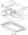
- FIG. 4 is a schematic three-dimensional view of an air sanitation device according to an embodiment of the present invention.
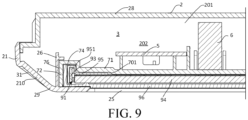
- FIG. 5 is a schematic cross-sectional view of an air sanitation device.
- a housing 2 includes a front wall 20 facing a front opening 10, a rear wall 22 facing a rear part of a storage compartment 101, a bottom wall 23, an upper wall 24, and a pair of side walls 21.
- the housing 2 may include a first housing 28 and a second housing 29.
- An air channel 3 is located between the first housing 28 and the second housing 29.
- An air inlet 31 is located at a side part of the housing 2.
- the air inlet 31 may be located at a single side or two sides of the housing 2.
- An air outlet 32 is located at a rear part of the housing 2. Air from the storage compartment 101 enters the housing 2 from two sides of the air sanitation device 1, and finally returns to the storage compartment 101 from the rear part of the housing 2.
- the housing 2 may be flat, and the air channel 3 in the housing 2 is also flat.
- a pair of boundary walls in opposite arrangement define at least a part of opposite boundaries of the air channel 3.
- a first boundary wall 3A is located above a second boundary wall 3B in the pair of boundary walls
- the first boundary wall 3A may also be referred to as an upper boundary wall
- the second boundary wall 3B may also be referred to as a lower boundary wall.
- the first boundary wall 3A is formed by the upper wall 24 of the housing 2.
- the second boundary wall 3B is located between the upper wall 24 and the bottom wall 23 of the housing 2.
- the second boundary wall 3B may be formed by a carrying member 7 for carrying an air detection device 5 and/or an air purification device 6. It should be understood that, in other embodiments of the present invention, the second boundary wall 3B may alternatively be formed by, for example, the bottom wall 23.
- the partition member 7 may include a carrying plate 7A for mounting the air detection device 5 and/or the air purification device 6.
- the air detection device 5 and/or the air purification device 6 may be fixed to the first side of the partition member 7.
- the air detection device 5, the air purification device 6, and the fan 4 are mounted at the first side of the partition member 7 away from the light outlet 25.
- the control unit 16 and the power supply unit 63 may also be mounted at the first side of the partition member 7.
- the illumination device 9 may be mounted at the second side of the partition member 7 facing the light outlet 25.
- the main board portion 71 and the side board 72 enclose an accommodating cavity 701 opening toward the light outlet 25, and the illumination device 9 is at least partially located in the accommodating cavity 701.
- the accommodating cavity 701 may constitute at least main part of the accommodating space 70.
- an illumination device 9 includes a light source 91.
- the light source 91 may include an LED light emitting element (not labeled) and a circuit board 93 carrying the light emitting element.
- the circuit board 93 extends along a side board 72 and is located at a side in the accommodating cavity 701.
- a partition member 7 may have a first slot 74 extending along the side board 72, and the circuit board 93 extends into the first slot 74.
- a depth of the first slot 74 is greater than depths of other parts of the accommodating cavity 701 in the partition member 7.
- the illumination device 9 may include a light guide plate 94 and a frame bar 95 fixing the light source 91 to an end of the light guide plate 94.
- the frame bar 95 has a protrusion 951 supporting the circuit board 93 and protruding toward the first slot 74, and the protrusion 951 extends into the first slot 74, so that the circuit board 93 also extends into the first slot 74.
- the illumination device 9 may include a light diffuser 96.
- the light diffuser 96 covers an outer side of the light guide plate 94, and the light source 91 and the light guide plate 94 are located between a main board portion 71 and the light diffuser 96.
- the light diffuser 96 may be fixed to the partition member 7, so that the light source 91 and the light guide plate 94 are mounted in the accommodating cavity 701.
- periphery of the light diffuser 96 may be connected to the side board 72 by buckles.
- the light diffuser 96 may be in a shallow tray shape opening toward the partition member 7, and the light source 91 and the light guide plate 94 are accommodated in the light diffuser 96.
- the light source 91, the light guide plate 94, and the light diffuser 96 may be together mounted at the partition member 7 after forming a pre-assembly unit.
- the light diffuser 96 is at least partially accommodated in the partition member 7.
- a side wall of the light diffuser 96 is located in the accommodating cavity 701.
- a surface of the light diffuser 96 facing a light outlet 25 does not exceed a distal end surface of the side board 72.
- the surface of the light diffuser 96 facing the light outlet 25 may be substantially flush with the distal end of the side board 72.
- the partition member 7 has an end surface 76 adjacent to a side wall 21 having an air inlet 31, and the end surface 76 is exposed in the air channel 3.
- a gap is disposed between the end surface 76 and the side wall 21 of the housing 2.
- the side wall 21 has an oblique portion 210, an angle is disposed between the oblique portion and the end surface 76, and the air inlet 31 passes through the oblique portion 210. This can reduce occurrence of a case that the air entering the air channel 3 directly flows toward the end surface 76 and is blocked.
- a second accommodating space 202 for accommodating an air detection device 5 and/or an air purification device 6 is disposed between the first housing 28 and the partition member 7. At least most of the air channel 3 is located between the first housing 28 and the partition member 7.
- the air inlet 31 is located in the second housing 29.
- the air inlet 31 may be at least partially lower than an upper surface of the main board portion 71 facing the first housing 28, and disposed obliquely so that air entering the air inlet 31 flows toward the first housing 28, thereby helping avoid a case that air entering the air channel 3 through the air inlet 31 is blocked by the partition member 7 and wind resistance is increased.
- a lower edge of the air outlet 32 may be substantially flush with an upper surface of the partition member 7 facing the first housing 28, so that air flows to the air outlet 32 along the upper surface of the partition member 7.
- the air outlet 32 may be disposed in the second housing 29.
- the second housing 29 may include a convex portion 295 protruding toward the partition member 7, an inner side of the convex portion 295 may be tightly adjacent to or be in contact with the side board 72 of the partition member 7, and the air outlet 32 is disposed on the convex portion 295, so that the air outlet 32 is tightly adjacent to the upper surface of the partition member 7, and air flowing along the upper surface of the partition member 7 can smoothly flow to the air outlet 32.
- a first sunk part 282 may be disposed at rear ends of two sides of the first housing 28, to reduce air blown to the control unit 16 or the power supply unit 63.
- a second sunk part 283 may be further disposed in the first housing 28, to accommodate cables and terminals.
- the air sanitation device 1 may be fixed in a depressed portion 1010 by using a plurality of hooks 285 located in the first housing 28.
Landscapes
- Engineering & Computer Science (AREA)
- Chemical & Material Sciences (AREA)
- Health & Medical Sciences (AREA)
- Combustion & Propulsion (AREA)
- Physics & Mathematics (AREA)
- Mechanical Engineering (AREA)
- Thermal Sciences (AREA)
- General Engineering & Computer Science (AREA)
- Animal Behavior & Ethology (AREA)
- Life Sciences & Earth Sciences (AREA)
- Epidemiology (AREA)
- General Health & Medical Sciences (AREA)
- Public Health (AREA)
- Veterinary Medicine (AREA)
- Chemical Kinetics & Catalysis (AREA)
- Analytical Chemistry (AREA)
- General Chemical & Material Sciences (AREA)
- Oil, Petroleum & Natural Gas (AREA)
- Disinfection, Sterilisation Or Deodorisation Of Air (AREA)
- Cold Air Circulating Systems And Constructional Details In Refrigerators (AREA)
Claims (11)
- Vorrichtung zur Luftdesinfektion (1) für einen Kühlschrank (100), die Folgendes umfasst:ein Gehäuse (2),einen Luftkanal (3), der in dem Gehäuse (2) angeordnet ist und einen Lufteinlass (31) und einen Luftauslass (32) umfasst,ein Gebläse (4), das in dem Luftkanal (3) angeordnet ist und Luft aus dem Lufteinlass (31) in den Luftkanal (3) fördert, die dann über den Luftauslass (32) aus dem Luftkanal (3) geleitet wird, undeine Lufterkennungsvorrichtung (5) mit einem Gassensor (51), der an einer Leiterplatte (50) befestigt ist, wobei der Luftkanal (3) so ausgelegt ist, dass er ein Strömen von Luft entlang einer Seite der Leiterplatte (50) ermöglicht, an der der Gassensor (51) befestigt ist, und eine Richtung, in die ein Einlass (41) des Gebläses (4) weist, einer Richtung entgegengesetzt ist, in der der Gassensor von der Leiterplatte vorsteht, wobei der Einlass (41) des Gebläses (4) nach unten hin offen istund das Gehäuse (2) eine obere Wand (24), eine untere Wand (23) und eine Seitenwand (21) umfasst,dadurch gekennzeichnet, dassdie Seitenwand (21) einen nach unten geneigten, schrägen Abschnitt (210) umfasst, der Lufteinlass (31) an dem schrägen Abschnitt (210) und die Lufterkennungsvorrichtung (5) zwischen dem Lufteinlass (31) und dem Einlass (41) des Gebläses (4) angeordnet ist.
- Vorrichtung zur Luftdesinfektion (1) nach Anspruch 1, gekennzeichnet durch ein Paar einander gegenüber angeordneter Begrenzungswände, die zumindest einen Teil des Luftkanals (3) definieren, wobei der Gassensor (51) zu einer ersten Begrenzungswand (3A) des Paars Begrenzungswände hin von der Leiterplatte (50) vorsteht, der Einlass (41) des Gebläses (4) zu einer zweiten Begrenzungswand (3B) des Paars Begrenzungswände weist und der Gassensor (51) näher an der ersten Begrenzungswand (3A) liegt als der Einlass (41) des Gebläses (4).
- Vorrichtung zur Luftdesinfektion (1) nach Anspruch 2, dadurch gekennzeichnet, dass die erste Begrenzungswand (3A) über der zweiten Begrenzungswand (3B) angeordnet ist, der Gassensor (51) von der Leiterplatte (50) nach oben zur ersten Begrenzungswand (3A) vorsteht, der Einlass (41) des Gebläses (4) nach unten zur zweiten Begrenzungswand (3B) weist und ein oberes Ende des Gassensors (51) höher liegt als der Einlass (41) des Gebläses (4).
- Vorrichtung zur Luftdesinfektion (1) nach Anspruch 2 oder 3, dadurch gekennzeichnet, dass der Gassensor (51) ein in einem Hohlraum (55) eingeschlossenes Erfassungselement (52) und eine durchlässige Schicht (54) umfasst, die einen Einlass des Hohlraums (55) bedeckt, und die durchlässige Schicht (54) höher liegt als der Einlass (41) des Gebläses (4).
- Vorrichtung zur Luftdesinfektion (1) nach Anspruch 4, dadurch gekennzeichnet, dass die durchlässige Schicht (54) höher liegt als zumindest ein Teil des Lufteinlasses (31).
- Vorrichtung zur Luftdesinfektion (1) nach einem der Ansprüche 2 bis 5, dadurch gekennzeichnet, dass die Leiterplatte (50) an einer Trägerplatte (7A) befestigt ist, sich zwischen der Leiterplatte (50) und der Trägerplatte (7A) ein Spalt (G1) befindet und der Spalt (G1) an einer stromaufwärtigen Seite der Leiterplatte (50) in der Nähe des Lufteinlasses (31) durch einen Verschlussabschnitt (58) geschlossen ist.
- Vorrichtung zur Luftdesinfektion (1) nach einem der vorhergehenden Ansprüche, gekennzeichnet durch die erste Begrenzungswand (3A) und die zweite Begrenzungswand (3B), die einander gegenüber angeordnet sind und so den Luftkanal (3) definieren, wobei die Lufterkennungsvorrichtung (5) an der zweiten Begrenzungswand (3B) befestigt und der Lufteinlass (31) so ausgelegt ist, dass Luft in den Lufteinlass (31) hineinströmen und dann schräg zur ersten Begrenzungswand (3A) hin strömen kann.
- Vorrichtung zur Luftdesinfektion (1) nach Anspruch 7, dadurch gekennzeichnet, dass der Einlass (41) des Gebläses (4) zur zweiten Begrenzungswand (3B) weist, so dass die Luft zumindest in manchen Segmenten zwischen der Lufterkennungsvorrichtung (5) und dem Einlass (41) des Gebläses (4) schräg nach unten strömt.
- Vorrichtung zur Luftdesinfektion (1) nach einem der vorhergehenden Ansprüche, dadurch gekennzeichnet, dass eine Luftreinigungsvorrichtung (6) Folgendes umfasst:
einen Luftfilter (62), der zwischen dem Lufteinlass (31) und dem Gebläse (4) angeordnet ist, und/oder eine Sterilisierungsvorrichtung (61), die zwischen dem Gebläse (4) und dem Luftauslass (32) angeordnet ist. - Kühlschrank (100), der durch ein Aufbewahrungsfach (101) und die Vorrichtung zur Luftdesinfektion (1) nach einem der vorhergehenden Ansprüche gekennzeichnet ist, wobei die Vorrichtung zur Luftdesinfektion (1) in dem Aufbewahrungsfach (101) angeordnet ist.
- Kühlschrank (100) nach Anspruch 10, dadurch gekennzeichnet, dass die Vorrichtung zur Luftdesinfektion (1) an einer oberen Wand (1010) des Aufbewahrungsfachs (101) befestigt und der Luftkanal (3) so ausgelegt ist, dass Luft aus einem hinteren Teil des Gehäuses (2) schräg nach unten geleitet werden kann.
Applications Claiming Priority (1)
| Application Number | Priority Date | Filing Date | Title |
|---|---|---|---|
| CN202011588466.XA CN114688808A (zh) | 2020-12-29 | 2020-12-29 | 用于冰箱的空气卫生装置以及冰箱 |
Publications (2)
| Publication Number | Publication Date |
|---|---|
| EP4023971A1 EP4023971A1 (de) | 2022-07-06 |
| EP4023971B1 true EP4023971B1 (de) | 2025-06-25 |
Family
ID=79024187
Family Applications (1)
| Application Number | Title | Priority Date | Filing Date |
|---|---|---|---|
| EP21214887.8A Active EP4023971B1 (de) | 2020-12-29 | 2021-12-15 | Vorrichtung zur luftdesinfektion für einen kühlschrank und kühlschrank |
Country Status (3)
| Country | Link |
|---|---|
| US (1) | US12140365B2 (de) |
| EP (1) | EP4023971B1 (de) |
| CN (1) | CN114688808A (de) |
Families Citing this family (1)
| Publication number | Priority date | Publication date | Assignee | Title |
|---|---|---|---|---|
| CN116734537A (zh) * | 2023-07-18 | 2023-09-12 | 长虹美菱股份有限公司 | 冰箱用净化装置及冰箱 |
Citations (3)
| Publication number | Priority date | Publication date | Assignee | Title |
|---|---|---|---|---|
| US20120181911A1 (en) * | 2011-01-17 | 2012-07-19 | Samsung Electronics Co., Ltd. | Refrigerator |
| CN110251704A (zh) * | 2019-05-15 | 2019-09-20 | 深圳市凯仕德科技有限公司 | 冰柜等离子杀菌除臭装置及其控制电路和杀菌除臭方法 |
| CN110878998A (zh) * | 2018-09-05 | 2020-03-13 | 博西华电器(江苏)有限公司 | 冰箱 |
Family Cites Families (16)
| Publication number | Priority date | Publication date | Assignee | Title |
|---|---|---|---|---|
| JPH05305211A (ja) * | 1992-04-28 | 1993-11-19 | Toshiba Corp | 空気清浄器 |
| JP3619679B2 (ja) * | 1998-07-09 | 2005-02-09 | ホシザキ電機株式会社 | 冷却貯蔵庫 |
| JP3940417B2 (ja) * | 2005-07-22 | 2007-07-04 | シャープ株式会社 | 空気調節装置 |
| WO2008132815A1 (ja) * | 2007-04-20 | 2008-11-06 | Panasonic Corporation | 冷蔵庫および除菌装置 |
| KR101822891B1 (ko) * | 2013-02-12 | 2018-01-29 | 엘지전자 주식회사 | 냉장고 및 그 금속 광촉매 필터 제조 방법 |
| KR20160068075A (ko) * | 2014-12-04 | 2016-06-15 | 서울바이오시스 주식회사 | 복합 기능 광촉매 모듈 |
| CN105148313A (zh) | 2015-09-30 | 2015-12-16 | 青岛海尔股份有限公司 | 用于冰箱的杀菌除臭装置和冰箱 |
| KR20170082084A (ko) * | 2016-01-05 | 2017-07-13 | 엘지전자 주식회사 | 냉장고 |
| KR101803628B1 (ko) * | 2016-02-16 | 2017-12-28 | 엘지전자 주식회사 | 냉장고 |
| KR102726049B1 (ko) * | 2017-02-16 | 2024-11-06 | 서울바이오시스 주식회사 | 흡입 팬을 포함하는 탈취 장치 및 그것을 포함하는 냉장고 |
| JP7185452B2 (ja) * | 2018-09-11 | 2022-12-07 | 東芝ライフスタイル株式会社 | 冷蔵庫 |
| KR102658295B1 (ko) * | 2019-01-25 | 2024-04-18 | 삼성전자주식회사 | 냉장고 |
| CN211551328U (zh) * | 2020-04-07 | 2020-09-22 | 深圳和而泰智能控制股份有限公司 | 照明装置 |
| CN114688783A (zh) * | 2020-12-29 | 2022-07-01 | 博西华电器(江苏)有限公司 | 冰箱 |
| CN114688784A (zh) * | 2020-12-29 | 2022-07-01 | 博西华电器(江苏)有限公司 | 冰箱 |
| CN114688809A (zh) * | 2020-12-29 | 2022-07-01 | 博西华电器(江苏)有限公司 | 用于冰箱的空气卫生装置以及冰箱 |
-
2020
- 2020-12-29 CN CN202011588466.XA patent/CN114688808A/zh active Pending
-
2021
- 2021-12-15 EP EP21214887.8A patent/EP4023971B1/de active Active
- 2021-12-29 US US17/564,420 patent/US12140365B2/en active Active
Patent Citations (3)
| Publication number | Priority date | Publication date | Assignee | Title |
|---|---|---|---|---|
| US20120181911A1 (en) * | 2011-01-17 | 2012-07-19 | Samsung Electronics Co., Ltd. | Refrigerator |
| CN110878998A (zh) * | 2018-09-05 | 2020-03-13 | 博西华电器(江苏)有限公司 | 冰箱 |
| CN110251704A (zh) * | 2019-05-15 | 2019-09-20 | 深圳市凯仕德科技有限公司 | 冰柜等离子杀菌除臭装置及其控制电路和杀菌除臭方法 |
Also Published As
| Publication number | Publication date |
|---|---|
| CN114688808A (zh) | 2022-07-01 |
| US20220205701A1 (en) | 2022-06-30 |
| US12140365B2 (en) | 2024-11-12 |
| EP4023971A1 (de) | 2022-07-06 |
Similar Documents
| Publication | Publication Date | Title |
|---|---|---|
| EP4023969B1 (de) | Kühlschrank | |
| EP4023972B1 (de) | Kühlschrank | |
| US8797704B2 (en) | Air blowing device and ion generating apparatus | |
| CN206842184U (zh) | 除臭模块以及包括除臭模块的储藏装置 | |
| KR102637740B1 (ko) | 탈취 모듈 및 그것을 포함하는 저장 장치 | |
| JP3090059B2 (ja) | 粉塵検知センサ付空気清浄機 | |
| EP4023971B1 (de) | Vorrichtung zur luftdesinfektion für einen kühlschrank und kühlschrank | |
| CN110878998B (zh) | 冰箱 | |
| EP4023970A1 (de) | Vorrichtung zur luftdesinfektion für einen kühlschrank und kühlschrank | |
| CN1430022A (zh) | 空调机 | |
| JP2022513028A (ja) | 空冷式冷蔵庫 | |
| KR102406614B1 (ko) | 칫솔 살균기 | |
| KR102653707B1 (ko) | 탈취 모듈 및 탈취 모듈을 포함하는 저장 장치 | |
| KR102636453B1 (ko) | 탈취 모듈 및 탈취 모듈을 포함하는 저장 장치 | |
| KR20090075054A (ko) | 스탠드형 김치냉장고의 탈취방법 및 시스템 | |
| JP3841066B2 (ja) | 高周波加熱装置 | |
| CN219913621U (zh) | 杀菌净味模组及制冷设备 | |
| EP4056912B1 (de) | Anzeigevorrichtung, luftreinigungsgerät und haushaltsgerät | |
| US9125961B2 (en) | Ion generating unit and electric device | |
| CN214512051U (zh) | 除臭装置 | |
| CN109432476B (zh) | 一种除臭机 | |
| JP2025014212A (ja) | 加湿装置 | |
| JP2025014209A (ja) | 加湿装置 | |
| JP2025014211A (ja) | 加湿装置 | |
| JP2004033270A (ja) | 空気清浄機 |
Legal Events
| Date | Code | Title | Description |
|---|---|---|---|
| PUAI | Public reference made under article 153(3) epc to a published international application that has entered the european phase |
Free format text: ORIGINAL CODE: 0009012 |
|
| STAA | Information on the status of an ep patent application or granted ep patent |
Free format text: STATUS: THE APPLICATION HAS BEEN PUBLISHED |
|
| AK | Designated contracting states |
Kind code of ref document: A1 Designated state(s): AL AT BE BG CH CY CZ DE DK EE ES FI FR GB GR HR HU IE IS IT LI LT LU LV MC MK MT NL NO PL PT RO RS SE SI SK SM TR |
|
| STAA | Information on the status of an ep patent application or granted ep patent |
Free format text: STATUS: REQUEST FOR EXAMINATION WAS MADE |
|
| 17P | Request for examination filed |
Effective date: 20230109 |
|
| RBV | Designated contracting states (corrected) |
Designated state(s): AL AT BE BG CH CY CZ DE DK EE ES FI FR GB GR HR HU IE IS IT LI LT LU LV MC MK MT NL NO PL PT RO RS SE SI SK SM TR |
|
| STAA | Information on the status of an ep patent application or granted ep patent |
Free format text: STATUS: EXAMINATION IS IN PROGRESS |
|
| 17Q | First examination report despatched |
Effective date: 20230310 |
|
| RIN1 | Information on inventor provided before grant (corrected) |
Inventor name: HU, CHENLI Inventor name: ZHOU, HAIQING Inventor name: ZHONG, WEI |
|
| RIN1 | Information on inventor provided before grant (corrected) |
Inventor name: HU, CHENLI Inventor name: ZHOU, HAIQING Inventor name: ZHONG, WEI |
|
| GRAP | Despatch of communication of intention to grant a patent |
Free format text: ORIGINAL CODE: EPIDOSNIGR1 |
|
| STAA | Information on the status of an ep patent application or granted ep patent |
Free format text: STATUS: GRANT OF PATENT IS INTENDED |
|
| RIC1 | Information provided on ipc code assigned before grant |
Ipc: F25D 27/00 20060101ALN20250203BHEP Ipc: A61L 9/22 20060101ALI20250203BHEP Ipc: A61L 9/20 20060101ALI20250203BHEP Ipc: F25D 17/04 20060101AFI20250203BHEP |
|
| INTG | Intention to grant announced |
Effective date: 20250220 |
|
| GRAS | Grant fee paid |
Free format text: ORIGINAL CODE: EPIDOSNIGR3 |
|
| GRAA | (expected) grant |
Free format text: ORIGINAL CODE: 0009210 |
|
| STAA | Information on the status of an ep patent application or granted ep patent |
Free format text: STATUS: THE PATENT HAS BEEN GRANTED |
|
| AK | Designated contracting states |
Kind code of ref document: B1 Designated state(s): AL AT BE BG CH CY CZ DE DK EE ES FI FR GB GR HR HU IE IS IT LI LT LU LV MC MK MT NL NO PL PT RO RS SE SI SK SM TR |
|
| REG | Reference to a national code |
Ref country code: GB Ref legal event code: FG4D |
|
| REG | Reference to a national code |
Ref country code: CH Ref legal event code: EP |
|
| REG | Reference to a national code |
Ref country code: DE Ref legal event code: R096 Ref document number: 602021032762 Country of ref document: DE |
|
| REG | Reference to a national code |
Ref country code: CH Ref legal event code: EP |
|
| REG | Reference to a national code |
Ref country code: IE Ref legal event code: FG4D |
|
| PG25 | Lapsed in a contracting state [announced via postgrant information from national office to epo] |
Ref country code: FI Free format text: LAPSE BECAUSE OF FAILURE TO SUBMIT A TRANSLATION OF THE DESCRIPTION OR TO PAY THE FEE WITHIN THE PRESCRIBED TIME-LIMIT Effective date: 20250625 |
|
| REG | Reference to a national code |
Ref country code: LT Ref legal event code: MG9D |
|
| PG25 | Lapsed in a contracting state [announced via postgrant information from national office to epo] |
Ref country code: NO Free format text: LAPSE BECAUSE OF FAILURE TO SUBMIT A TRANSLATION OF THE DESCRIPTION OR TO PAY THE FEE WITHIN THE PRESCRIBED TIME-LIMIT Effective date: 20250925 Ref country code: GR Free format text: LAPSE BECAUSE OF FAILURE TO SUBMIT A TRANSLATION OF THE DESCRIPTION OR TO PAY THE FEE WITHIN THE PRESCRIBED TIME-LIMIT Effective date: 20250926 |
|
| PG25 | Lapsed in a contracting state [announced via postgrant information from national office to epo] |
Ref country code: BG Free format text: LAPSE BECAUSE OF FAILURE TO SUBMIT A TRANSLATION OF THE DESCRIPTION OR TO PAY THE FEE WITHIN THE PRESCRIBED TIME-LIMIT Effective date: 20250625 |
|
| PG25 | Lapsed in a contracting state [announced via postgrant information from national office to epo] |
Ref country code: HR Free format text: LAPSE BECAUSE OF FAILURE TO SUBMIT A TRANSLATION OF THE DESCRIPTION OR TO PAY THE FEE WITHIN THE PRESCRIBED TIME-LIMIT Effective date: 20250625 |
|
| PG25 | Lapsed in a contracting state [announced via postgrant information from national office to epo] |
Ref country code: RS Free format text: LAPSE BECAUSE OF FAILURE TO SUBMIT A TRANSLATION OF THE DESCRIPTION OR TO PAY THE FEE WITHIN THE PRESCRIBED TIME-LIMIT Effective date: 20250925 |
|
| PG25 | Lapsed in a contracting state [announced via postgrant information from national office to epo] |
Ref country code: LV Free format text: LAPSE BECAUSE OF FAILURE TO SUBMIT A TRANSLATION OF THE DESCRIPTION OR TO PAY THE FEE WITHIN THE PRESCRIBED TIME-LIMIT Effective date: 20250625 |
|
| REG | Reference to a national code |
Ref country code: NL Ref legal event code: MP Effective date: 20250625 |
|
| PG25 | Lapsed in a contracting state [announced via postgrant information from national office to epo] |
Ref country code: NL Free format text: LAPSE BECAUSE OF FAILURE TO SUBMIT A TRANSLATION OF THE DESCRIPTION OR TO PAY THE FEE WITHIN THE PRESCRIBED TIME-LIMIT Effective date: 20250625 |
|
| PG25 | Lapsed in a contracting state [announced via postgrant information from national office to epo] |
Ref country code: PT Free format text: LAPSE BECAUSE OF FAILURE TO SUBMIT A TRANSLATION OF THE DESCRIPTION OR TO PAY THE FEE WITHIN THE PRESCRIBED TIME-LIMIT Effective date: 20251027 |
|
| REG | Reference to a national code |
Ref country code: AT Ref legal event code: MK05 Ref document number: 1806799 Country of ref document: AT Kind code of ref document: T Effective date: 20250625 |
|
| PG25 | Lapsed in a contracting state [announced via postgrant information from national office to epo] |
Ref country code: IS Free format text: LAPSE BECAUSE OF FAILURE TO SUBMIT A TRANSLATION OF THE DESCRIPTION OR TO PAY THE FEE WITHIN THE PRESCRIBED TIME-LIMIT Effective date: 20251025 |
|
| PG25 | Lapsed in a contracting state [announced via postgrant information from national office to epo] |
Ref country code: AT Free format text: LAPSE BECAUSE OF FAILURE TO SUBMIT A TRANSLATION OF THE DESCRIPTION OR TO PAY THE FEE WITHIN THE PRESCRIBED TIME-LIMIT Effective date: 20250625 Ref country code: SM Free format text: LAPSE BECAUSE OF FAILURE TO SUBMIT A TRANSLATION OF THE DESCRIPTION OR TO PAY THE FEE WITHIN THE PRESCRIBED TIME-LIMIT Effective date: 20250625 |
|
| PG25 | Lapsed in a contracting state [announced via postgrant information from national office to epo] |
Ref country code: CZ Free format text: LAPSE BECAUSE OF FAILURE TO SUBMIT A TRANSLATION OF THE DESCRIPTION OR TO PAY THE FEE WITHIN THE PRESCRIBED TIME-LIMIT Effective date: 20250625 |
|
| PG25 | Lapsed in a contracting state [announced via postgrant information from national office to epo] |
Ref country code: PL Free format text: LAPSE BECAUSE OF FAILURE TO SUBMIT A TRANSLATION OF THE DESCRIPTION OR TO PAY THE FEE WITHIN THE PRESCRIBED TIME-LIMIT Effective date: 20250625 |
|
| PG25 | Lapsed in a contracting state [announced via postgrant information from national office to epo] |
Ref country code: EE Free format text: LAPSE BECAUSE OF FAILURE TO SUBMIT A TRANSLATION OF THE DESCRIPTION OR TO PAY THE FEE WITHIN THE PRESCRIBED TIME-LIMIT Effective date: 20250625 |
|
| PG25 | Lapsed in a contracting state [announced via postgrant information from national office to epo] |
Ref country code: SK Free format text: LAPSE BECAUSE OF FAILURE TO SUBMIT A TRANSLATION OF THE DESCRIPTION OR TO PAY THE FEE WITHIN THE PRESCRIBED TIME-LIMIT Effective date: 20250625 |
|
| PG25 | Lapsed in a contracting state [announced via postgrant information from national office to epo] |
Ref country code: ES Free format text: LAPSE BECAUSE OF FAILURE TO SUBMIT A TRANSLATION OF THE DESCRIPTION OR TO PAY THE FEE WITHIN THE PRESCRIBED TIME-LIMIT Effective date: 20250625 |