EP4023920B1 - Anschlussvorrichtung zum verbinden von rohren - Google Patents
Anschlussvorrichtung zum verbinden von rohren Download PDFInfo
- Publication number
- EP4023920B1 EP4023920B1 EP20710408.4A EP20710408A EP4023920B1 EP 4023920 B1 EP4023920 B1 EP 4023920B1 EP 20710408 A EP20710408 A EP 20710408A EP 4023920 B1 EP4023920 B1 EP 4023920B1
- Authority
- EP
- European Patent Office
- Prior art keywords
- pipe
- pipes
- mounting part
- fitting
- sealing
- Prior art date
- Legal status (The legal status is an assumption and is not a legal conclusion. Google has not performed a legal analysis and makes no representation as to the accuracy of the status listed.)
- Active
Links
Images






Classifications
-
- F—MECHANICAL ENGINEERING; LIGHTING; HEATING; WEAPONS; BLASTING
- F16—ENGINEERING ELEMENTS AND UNITS; GENERAL MEASURES FOR PRODUCING AND MAINTAINING EFFECTIVE FUNCTIONING OF MACHINES OR INSTALLATIONS; THERMAL INSULATION IN GENERAL
- F16L—PIPES; JOINTS OR FITTINGS FOR PIPES; SUPPORTS FOR PIPES, CABLES OR PROTECTIVE TUBING; MEANS FOR THERMAL INSULATION IN GENERAL
- F16L21/00—Joints with sleeve or socket
- F16L21/02—Joints with sleeve or socket with elastic sealing rings between pipe and sleeve or between pipe and socket, e.g. with rolling or other prefabricated profiled rings
- F16L21/03—Joints with sleeve or socket with elastic sealing rings between pipe and sleeve or between pipe and socket, e.g. with rolling or other prefabricated profiled rings placed in the socket before connection
-
- F—MECHANICAL ENGINEERING; LIGHTING; HEATING; WEAPONS; BLASTING
- F16—ENGINEERING ELEMENTS AND UNITS; GENERAL MEASURES FOR PRODUCING AND MAINTAINING EFFECTIVE FUNCTIONING OF MACHINES OR INSTALLATIONS; THERMAL INSULATION IN GENERAL
- F16L—PIPES; JOINTS OR FITTINGS FOR PIPES; SUPPORTS FOR PIPES, CABLES OR PROTECTIVE TUBING; MEANS FOR THERMAL INSULATION IN GENERAL
- F16L21/00—Joints with sleeve or socket
- F16L21/02—Joints with sleeve or socket with elastic sealing rings between pipe and sleeve or between pipe and socket, e.g. with rolling or other prefabricated profiled rings
-
- F—MECHANICAL ENGINEERING; LIGHTING; HEATING; WEAPONS; BLASTING
- F16—ENGINEERING ELEMENTS AND UNITS; GENERAL MEASURES FOR PRODUCING AND MAINTAINING EFFECTIVE FUNCTIONING OF MACHINES OR INSTALLATIONS; THERMAL INSULATION IN GENERAL
- F16L—PIPES; JOINTS OR FITTINGS FOR PIPES; SUPPORTS FOR PIPES, CABLES OR PROTECTIVE TUBING; MEANS FOR THERMAL INSULATION IN GENERAL
- F16L19/00—Joints in which sealing surfaces are pressed together by means of a member, e.g. a swivel nut, screwed on, or into, one of the joint parts
- F16L19/06—Joints in which sealing surfaces are pressed together by means of a member, e.g. a swivel nut, screwed on, or into, one of the joint parts in which radial clamping is obtained by wedging action on non-deformed pipe ends
- F16L19/065—Joints in which sealing surfaces are pressed together by means of a member, e.g. a swivel nut, screwed on, or into, one of the joint parts in which radial clamping is obtained by wedging action on non-deformed pipe ends the wedging action being effected by means of a ring
- F16L19/0653—Joints in which sealing surfaces are pressed together by means of a member, e.g. a swivel nut, screwed on, or into, one of the joint parts in which radial clamping is obtained by wedging action on non-deformed pipe ends the wedging action being effected by means of a ring the ring being rotatably connected to one of the connecting parts
-
- B—PERFORMING OPERATIONS; TRANSPORTING
- B25—HAND TOOLS; PORTABLE POWER-DRIVEN TOOLS; MANIPULATORS
- B25B—TOOLS OR BENCH DEVICES NOT OTHERWISE PROVIDED FOR, FOR FASTENING, CONNECTING, DISENGAGING, OR HOLDING
- B25B27/00—Hand tools, specially adapted for fitting together or separating parts or objects whether or not involving some deformation, not otherwise provided for
- B25B27/02—Hand tools, specially adapted for fitting together or separating parts or objects whether or not involving some deformation, not otherwise provided for for connecting objects by press fit or detaching same
-
- F—MECHANICAL ENGINEERING; LIGHTING; HEATING; WEAPONS; BLASTING
- F16—ENGINEERING ELEMENTS AND UNITS; GENERAL MEASURES FOR PRODUCING AND MAINTAINING EFFECTIVE FUNCTIONING OF MACHINES OR INSTALLATIONS; THERMAL INSULATION IN GENERAL
- F16J—PISTONS; CYLINDERS; SEALINGS
- F16J15/00—Sealings
- F16J15/02—Sealings between relatively-stationary surfaces
- F16J15/021—Sealings between relatively-stationary surfaces with elastic packing
-
- F—MECHANICAL ENGINEERING; LIGHTING; HEATING; WEAPONS; BLASTING
- F16—ENGINEERING ELEMENTS AND UNITS; GENERAL MEASURES FOR PRODUCING AND MAINTAINING EFFECTIVE FUNCTIONING OF MACHINES OR INSTALLATIONS; THERMAL INSULATION IN GENERAL
- F16J—PISTONS; CYLINDERS; SEALINGS
- F16J15/00—Sealings
- F16J15/02—Sealings between relatively-stationary surfaces
- F16J15/06—Sealings between relatively-stationary surfaces with solid packing compressed between sealing surfaces
- F16J15/10—Sealings between relatively-stationary surfaces with solid packing compressed between sealing surfaces with non-metallic packing
- F16J15/104—Sealings between relatively-stationary surfaces with solid packing compressed between sealing surfaces with non-metallic packing characterised by structure
- F16J15/106—Sealings between relatively-stationary surfaces with solid packing compressed between sealing surfaces with non-metallic packing characterised by structure homogeneous
-
- F—MECHANICAL ENGINEERING; LIGHTING; HEATING; WEAPONS; BLASTING
- F16—ENGINEERING ELEMENTS AND UNITS; GENERAL MEASURES FOR PRODUCING AND MAINTAINING EFFECTIVE FUNCTIONING OF MACHINES OR INSTALLATIONS; THERMAL INSULATION IN GENERAL
- F16L—PIPES; JOINTS OR FITTINGS FOR PIPES; SUPPORTS FOR PIPES, CABLES OR PROTECTIVE TUBING; MEANS FOR THERMAL INSULATION IN GENERAL
- F16L13/00—Non-disconnectable pipe joints, e.g. soldered, adhesive, or caulked joints
- F16L13/14—Non-disconnectable pipe joints, e.g. soldered, adhesive, or caulked joints made by plastically deforming the material of the pipe, e.g. by flanging, rolling
- F16L13/141—Non-disconnectable pipe joints, e.g. soldered, adhesive, or caulked joints made by plastically deforming the material of the pipe, e.g. by flanging, rolling by crimping or rolling from the outside
- F16L13/142—Non-disconnectable pipe joints, e.g. soldered, adhesive, or caulked joints made by plastically deforming the material of the pipe, e.g. by flanging, rolling by crimping or rolling from the outside with a sealing element inserted into the female part before crimping or rolling
-
- F—MECHANICAL ENGINEERING; LIGHTING; HEATING; WEAPONS; BLASTING
- F16—ENGINEERING ELEMENTS AND UNITS; GENERAL MEASURES FOR PRODUCING AND MAINTAINING EFFECTIVE FUNCTIONING OF MACHINES OR INSTALLATIONS; THERMAL INSULATION IN GENERAL
- F16L—PIPES; JOINTS OR FITTINGS FOR PIPES; SUPPORTS FOR PIPES, CABLES OR PROTECTIVE TUBING; MEANS FOR THERMAL INSULATION IN GENERAL
- F16L19/00—Joints in which sealing surfaces are pressed together by means of a member, e.g. a swivel nut, screwed on, or into, one of the joint parts
- F16L19/08—Joints in which sealing surfaces are pressed together by means of a member, e.g. a swivel nut, screwed on, or into, one of the joint parts with metal rings which bite into the wall of the pipe
-
- F—MECHANICAL ENGINEERING; LIGHTING; HEATING; WEAPONS; BLASTING
- F16—ENGINEERING ELEMENTS AND UNITS; GENERAL MEASURES FOR PRODUCING AND MAINTAINING EFFECTIVE FUNCTIONING OF MACHINES OR INSTALLATIONS; THERMAL INSULATION IN GENERAL
- F16L—PIPES; JOINTS OR FITTINGS FOR PIPES; SUPPORTS FOR PIPES, CABLES OR PROTECTIVE TUBING; MEANS FOR THERMAL INSULATION IN GENERAL
- F16L21/00—Joints with sleeve or socket
- F16L21/08—Joints with sleeve or socket with additional locking means
-
- F—MECHANICAL ENGINEERING; LIGHTING; HEATING; WEAPONS; BLASTING
- F16—ENGINEERING ELEMENTS AND UNITS; GENERAL MEASURES FOR PRODUCING AND MAINTAINING EFFECTIVE FUNCTIONING OF MACHINES OR INSTALLATIONS; THERMAL INSULATION IN GENERAL
- F16L—PIPES; JOINTS OR FITTINGS FOR PIPES; SUPPORTS FOR PIPES, CABLES OR PROTECTIVE TUBING; MEANS FOR THERMAL INSULATION IN GENERAL
- F16L55/00—Devices or appurtenances for use in, or in connection with, pipes or pipe systems
-
- F—MECHANICAL ENGINEERING; LIGHTING; HEATING; WEAPONS; BLASTING
- F16—ENGINEERING ELEMENTS AND UNITS; GENERAL MEASURES FOR PRODUCING AND MAINTAINING EFFECTIVE FUNCTIONING OF MACHINES OR INSTALLATIONS; THERMAL INSULATION IN GENERAL
- F16L—PIPES; JOINTS OR FITTINGS FOR PIPES; SUPPORTS FOR PIPES, CABLES OR PROTECTIVE TUBING; MEANS FOR THERMAL INSULATION IN GENERAL
- F16L13/00—Non-disconnectable pipe joints, e.g. soldered, adhesive, or caulked joints
- F16L13/14—Non-disconnectable pipe joints, e.g. soldered, adhesive, or caulked joints made by plastically deforming the material of the pipe, e.g. by flanging, rolling
- F16L2013/145—Tools specially adapted therefor
Definitions
- the present invention relates to a fitting apparatus for connecting pipes, and more particularly, to a fitting apparatus for connecting pipes, which firmly connects a pair of pipes to each other so as to maintain airtightness.
- pipe connectors are used to connect various types of pipes that are constructed in construction and civil engineering, and these pipe connectors are formed in various shapes according to the size and type of pipe.
- Patent documents 2 and 3 disclose fixing apparatuses which make use of a fitting or main body with a sealing ring and a grip ring or stopper ring.
- a method is used in which a water stop ring is inserted into a connector into which a pipe is inserted, and then the pipe is inserted and connected.
- the water stop ring presses the outer surface of the pipe to prevent leakage of a fluid flowing into the pipe.
- the conventional small-diameter pipe connector is formed so that the water stop ring has elasticity, shape deformation occurs easily due to a load of the pipe, an angle change by an external force, and the like, and thus it is difficult to stably fix the pipe.
- the present invention has been made in an effort to solve the above-described problems associated with prior art and to provide a fitting apparatus for connecting pipes that can greatly improve a water stop force and firmly fix the pipes.
- the present invention has been made in an effort to provide a fitting apparatus for connecting pipes that is simple in configuration and easy to be installed.
- This fitting apparatus for connecting pipes includes a fitting unit which includes a first body into which a first pipe is inserted and a second body which is connected to the first body to form a pipe insertion space therein together with the first body and into which a second pipe is inserted, wherein in the first body and the second body, a first recessed groove and a second recessed groove spaced apart inward from the first recessed groove are formed along an inner circumferential surface thereof, respectively, a compression member which is provided in the first recessed groove to compress and fix the first pipe or the second pipe, and a sealing member which is provided in the second recessed groove to maintain airtightness between the fitting unit and the first pipe or between the fitting unit and the second pipe.
- the first body and the second body include a first member mounting part having the first recessed groove formed on the inner circumferential surface thereof, a second member mounting part having the second recessed groove formed on the inner circumferential surface thereof, a groove separation part formed between the first member mounting part and the second member mounting part, and an inner extension part which extends inward from the second member mounting part to connect the first body and the second body to each other.
- the first body and the second body may further include an outer extension part extending outward from the first member mounting part.
- the first member mounting part and the second member mounting part are formed to have outer diameters larger than those of the groove separation part and the inner extension part.
- a length of the inner extension part may be formed longer than the length of the groove separation part.
- the compression member may be seated on the first recessed groove and formed to have a non-closed shape in which a part of the circumference is opened to reduce a diameter by compression applied to the outer circumferential surface of the fitting unit and compress the first pipe or the second pipe.
- a longitudinal section of the compression member may include a main compression region having a predetermined shape.
- the longitudinal section of the compression member may further include an auxiliary compression region protruding toward the center of the pipe insertion space from the main compression region.
- the longitudinal section of the compression member may further include an auxiliary groove recessed inward from the main compression region.
- the sealing member may be formed to have elasticity to be seated on the second recessed groove and formed in a ring shape.
- the sealing member may include an auxiliary sealing protrusion protruding spirally along the outer surface of the sealing member.
- a longitudinal section of the sealing member may include a main sealing region having a predetermined shape.
- the longitudinal section of the sealing member may further include an auxiliary sealing region protruding outward from the main sealing region.
- the longitudinal section of the sealing member may be formed so that a pair of main sealing regions is connected to each other.
- the fitting apparatus for connecting the pipes further includes a pressing unit which is mounted to cover an outer circumferential surface of the first body or the second body and press the outer circumferential surface of the first body or the second body.
- the pressing unit includes a pressing body which has a fitting unit insertion space into which the first body or the second body is inserted and covers and presses the outer circumferential surface of the first body or the second body.
- the first member mounting part and the second member mounting part are formed to have outer diameters larger than those of the groove separation part and the inner extension part, and in the pressing body, a first seating groove on which the first member mounting part is seated and a second seating groove on which the second member mounting part is seated is formed along an inner circumferential surface thereof.
- the fitting apparatus for connecting the pipes of the present invention for solving the above problems has the following effects.
- the fitting apparatus of the present invention has advantages of stably fixing the pipes by the compression member and the sealing member which are in contact with each pipe fixed to the fitting unit and greatly improving the airtightness.
- the fitting apparatus of the present invention is not provided with a separate fixing device or the like and thus is simple in configuration and an installation method thereof is very easy, the fitting apparatus has an advantage of greatly reducing the time and cost required for construction.
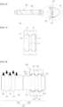
- FIG. 1 is a view illustrating an external appearance of a fitting apparatus for connecting pipes according to an embodiment of the present invention
- FIG. 2 is a view illustrating an internal structure of the fitting apparatus for connecting the pipes according to an embodiment of the present invention.
- FIG. 3 is a view illustrating an appearance of a fitting unit 110 in the fitting apparatus for connecting the pipes according to an embodiment of the present invention.
- the fitting apparatus for connecting the pipes includes a fitting unit 110, a compression member 120, and a sealing member 130.
- the fitting unit 110 has a pipe insertion space S1 formed therein so that different pipes may be inserted into both sides thereof and is formed in a tubular shape as a whole.
- the fitting unit 110 includes a first body 110a into which a first pipe is inserted and a second body 110b into which a second pipe is inserted.
- the first body 110a and the second body 110b have a symmetrical shape in both directions based on a central line of the fitting unit 110 and have the pipe insertion space S1 formed therein.
- a first recessed groove 112a and a second recessed groove 114a spaced apart inward from the first recessed groove 112a are formed along an inner circumferential surface thereof, respectively.
- the compression member 120 is provided in the first recessed groove 112a
- the sealing member 130 is provided in the second recessed groove 114a.
- each of the first body 110a and the second body 110b has a form including a first member mounting part 112 having the first recessed groove 112a formed on an inner circumferential surface thereof, a second member mounting part 114 having the second recessed groove 114a formed on an inner circumferential surface thereof, a groove separation part 113 formed between the first member mounting part 112 and the second member mounting part 114, an inner extension part 111 extending inward from the second member mounting part 114 to connect the first body 110a and the second body 110b to each other, and an outer extension part 116 extending outward from the first member mounting part 112.
- first body 110a and the second body 110b have a form in which the inner extension part 111, the second member mounting part 114, the groove separation part 113, the first member mounting part 112, and the outer extension part 116 are sequentially connected to each other outward from the center of the fitting unit 110.
- the first member mounting part 112 and the second member mounting part 114 are formed to have outer diameters larger than those of the groove separation part 113, the outer extension part 116, and the inner extension part 111. Accordingly, the fitting unit 110 is formed in a tubular shape as a whole, and has a form in which a plurality of protrusions is formed on an outer circumferential surface thereof.
- first member mounting part 112 and the second member mounting part 114 are formed in the first body 110a and the second body 110b, respectively, but the present invention is not limited thereto, and the first member mounting part 112 and the second member mounting part 114 may also be formed in plural. In this case, the compression member 120 or the sealing member 130 may also be provided in plural.
- the length of the inner extension part 111 may be formed longer than the length of the groove separation part 113. The reason as such is to form a wider internal space of the inner extension part 111 to prevent an end of the pipe inserted into the fitting unit 110 from being deformed by a pressing force of the pressing unit 150 (see FIG. 8 ) to be described below.
- a ring-shaped protrusion protruding by a predetermined height may be formed on the inner circumferential surface of the center of the fitting unit 110 in which the first body 110a and the second body 110b are connected to each other. This is to limit a maximum insertion depth of the first pipe and the second pipe.
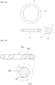
- FIGS. 4 and 5 are views illustrating an appearance of the compression member 120 in the fitting apparatus for connecting the pipes according to an embodiment of the present invention.
- the compression member 120 is a component which is provided in the first recessed groove 112a to press and fix the first pipe or the second pipe.
- the compression member 120 is seated on the first recessed groove 112a and is formed in a non-closed shape in which a part of the circumference is opened. That is, the compression member 120 is formed in an unfinished ring shape in which an opening 121 is formed in a part of the entire circumference.
- the compression member 120 may be deformed by the compression applied to the outer circumferential surface of the fitting unit 110 to reduce a diameter thereof, and press and fix the first pipe or the second pipe inserted into the fitting unit 110.
- the compression member 120 may be formed of a metallic material, and the first pipe or the second pipe is plastically deformed by the compression member 120 to be fixed so as not to be separated from the fitting unit 110.
- a longitudinal section of the compression member 120 includes a main compression region 122 having a predetermined shape.
- the main compression region 122 has a circular shape.
- both ends 126 and 126' based on the opening 121 may also be finished in a hemispherical round form as illustrated in the left side of FIG. 5 , or may also be finished in a chamfered form as illustrated in the right side of FIG. 5 . This is to prevent the ends 126 and 126' of the compression member 120 from damaging the first pipe or the second pipe.
- FIG. 6 is a view illustrating an appearance of the sealing member 130 in the fitting apparatus for connecting the pipes according to an embodiment of the present invention.
- the sealing member 130 is a component which is provided in the second recessed groove 114a to maintain the airtightness between the fitting unit 110 and the first pipe, or between the fitting unit 110 and the second pipe.
- the reason why the sealing member 130 is provided inside the compression member 120 described above is to prevent a fluid flowing between the first pipe and the second pipe from being leaked toward the compression member 120. That is, the sealing member 130 is provided close to the center side of the fitting unit 110 and serves to prevent the leakage of the fluid in advance.
- the sealing member 130 is formed to have elasticity, seated on the second recessed groove 114a, and formed in a ring shape as a whole.
- the sealing member 130 has a form including an auxiliary sealing protrusion 136 protruding in a spiral form along the outer surface of the sealing member 130.
- the auxiliary sealing protrusion 136 is to allow the sealing member 130 to have a greater water stop force between the fitting unit 110 and the first pipe, or between the fitting unit 110 and the second pipe.
- the longitudinal section of the sealing member 130 may include a main sealing region 132 having a predetermined shape and an auxiliary sealing region 134 protruding outward from the main sealing region 132.
- the main sealing region 132 is formed to have a circular shape
- the auxiliary sealing region 134 has a shape in which a pair of auxiliary sealing regions protrudes to both sides of the main sealing region 132.
- Such a longitudinal section shape allows the sealing member 130 to be more strongly in close contact with the first pipe or the second pipe, thereby improving the water stop force.
- the pipe may be scratched during use in manufacturing, transportation, and construction sites, and an allowable range thereof is 22% of a tube thickness.
- an allowable range thereof is 22% of a tube thickness.
- the pipe is sensitive to the water stop force and the durability when applied to an actual product, there is a problem that it is difficult to maintain a desired water stop force when the pipe has a scratch of 22% thickness.
- a refrigerant such as helium used in an air conditioning system of a fluid passing through the pipe is sensitive to scratches, thereby increasing a possibility of leakage.
- the compressive force with the pipe may be increased to maintain the water stop force.
- the present invention has an effect of maintaining the water stop force even if there are scratches on the pipe.
- FIG. 7 is a view illustrating an appearance of the pressing unit 150 in the fitting apparatus for connecting the pipes according to an embodiment of the present invention
- FIG. 8 is a view illustrating an appearance in which the pressing unit 150 is mounted on the fitting unit 110 in the fitting apparatus for connecting the pipes according to an embodiment of the present invention.
- the fitting apparatus for connecting the pipes according to the present invention includes the pressing unit 150.
- the pressing unit 150 is a component which is mounted to cover the outer circumferential surface of the first body 110a or the second body 110b, presses the outer circumferential surface of the first body 110a or the second body 110b to deform the compression member 120 provided inside the fitting unit 110, and applies the pressure to the first pipe or the second pipe to strongly constrain the first pipe or the second pipe.
- the pressing unit 150 includes a pressing body 151 which has a fitting unit insertion space S2 into which the first body 110a or the second body 110b is inserted, and covers and presses the outer circumferential surface of the first body 110a or the second body 110b.
- the pressing body 151 has a first seating groove 152 on which the first member mounting part 112 of the fitting unit 110 is seated, and a second seating groove 154 on which the second member mounting part 114 is seated, which are formed along the inner circumferential surface thereof.
- the pressing body 151 is mounted on the fitting unit 110 as illustrated in FIG. 8 , the pressing body 151 is in contact with the inner extension part 111, the second member mounting part 114, the groove separation part 113, the first member mounting part 112, and the outer extension part 116 of the first body 110a or the second body 110b, respectively, to apply the pressing force.
- the pressing unit 150 of such a form may increase a fastening force so that the first pipe or the second pipe is not separated.
- the pressing unit 150 is formed so as to press only a part of the inner extension part 111 to prevent the end of the first pipe or the second pipe from being deformed.
- an inner circumferential surface 153 of the first seating groove 152 and the second seating groove 154 may have various cross-sectional shapes.
- the cross section of the inner circumferential surface 153 of the first seating groove 152 and the second seating groove 154 has a flat shape.
- FIG. 9 is a view illustrating another embodiment of a fitting unit 210 in a fitting apparatus for connecting pipes of the present invention.
- the fitting unit 210 of another embodiment illustrated in FIG. 9 also includes a first body 210a and a second body 210b, and has a pipe insertion space S1 formed therein.
- the first body 210a and the second body 210b are formed in a form in which an outer extension part is omitted. That is, in the present embodiment, the first body 210a and the second body 210b have a form in which an inner extension part 211, a second member mounting part 214, a groove separation part 213, and a first member mounting part 212 are sequentially connected to each other outward from the center of the fitting unit 210.
- the fitting unit 210 may be formed to have a shorter length by omitting the outer extension part.
- FIGS. 10 to 13 are views illustrating other embodiments of compression members 220, 320, 420, and 520 in the fitting apparatus for connecting the pipes of the present invention.
- the compression members 220, 320, 420, and 520 have a common characteristic in which openings 221, 321, 421, and 521 are formed in a part of an entire circumference, respectively, to form an unfinished ring shape.
- a longitudinal section of the compression member 220 is formed to have a main compression region 222 of a rectangular shape as a whole, and a longitudinal section of the compression member 320 of the embodiment illustrated in FIG. 11 is formed to have a main compression region 322 of a rhombic shape.
- a longitudinal section of the compression member 420 of the embodiment illustrated in FIG. 12 is formed to have a main compression region 422 of a semicircular shape and an auxiliary compression region 424 protruding toward a center of the pipe insertion space of the fitting unit from the main compression region 422.
- the auxiliary compression region 424 may more strongly compress the first pipe or the second pipe.
- a longitudinal section of the compression member 520 of the embodiment illustrated in FIG. 13 includes a main compression region 522 having an elongated semicircular end portion and an auxiliary groove 524 recessed inward from the main compression region.
- the auxiliary groove 524 is formed in a recessed shape and protrusions formed at both sides may more strongly compress the first pipe or the second pipe.
- the compression members 220, 320, 420, and 520 may be formed in various shapes.
- FIGS. 14 to 17 are views illustrating other embodiments of sealing members 230, 330, and 430 in the fitting apparatus for connecting the pipes of the present invention.
- the sealing members 230, 330, 430, and 530 have elasticity, respectively, and have a common characteristic to be formed in a ring shape.
- the sealing member 230 includes an auxiliary sealing protrusion 236, and a longitudinal section thereof is formed to have a circular main sealing region 232 and an auxiliary sealing region 234 protruding toward the center of the fitting unit from the main sealing region 232.
- the sealing member 330 is configured to include only a main sealing region 332 having a rectangular longitudinal section so that a surface in contact with the first pipe or the second pipe is flatly formed to more increase a contact area.
- the sealing member 430 is formed to have a longitudinal section so that a pair of main sealing regions 432a and 432b are connected to each other and the pair of main sealing regions 432a and 432b are formed in a circular shape.
- a recessed connection groove 434 is formed between the pair of main sealing regions 432a and 432b, and accordingly, the sealing member 432 of the present embodiment forms a plurality of contact points with the first pipe or the second pipe to improve the water stop force.
- the sealing member 530 includes an auxiliary sealing protrusion 536 along the circumference as described above and a longitudinal section thereof is formed to include a main sealing region 532 having a circular shape, an auxiliary sealing region 534 protruding toward a center of the fitting unit 110 from the main sealing region 532, and wing parts 538 protruding to both sides about the auxiliary sealing region 534.
- auxiliary sealing region 534 protruding from the main sealing region 532 and the wing parts 538 have a plurality of contact points in each pipe and adhere to each other to improve the water stop force.
- auxiliary sealing protrusion 536 may protrude so that the height of a central portion between the wing parts 538 is higher than the height of the wing parts 538 at both ends.
- the auxiliary sealing protrusion 536 in a region facing the pipe between the wing parts 538, has a protruding height increased toward the center and the auxiliary sealing protrusion 536 in a region in contact with the fitting unit 110 on the wing parts 538 is uniformly formed.
- the auxiliary sealing protrusion 536 is formed in a spiral shape to pass through the main sealing region 532 and the auxiliary sealing region 534, but has a uniform protruding height in the main sealing region 532 and has a relatively high protruding height in the auxiliary sealing region 534.
- the protruding height is gradually increased toward the center of the auxiliary sealing region 536 from the wing parts 538 of the auxiliary sealing protrusion 536.
- the auxiliary sealing protrusion 536 of the sealing member 530 has a uniform protruding height in the main sealing region 532 and extends to the wing parts 538 to have no change in height.
- the height is linearly increased toward the center from both ends where the wing parts 538 are located.
- the auxiliary sealing protrusion 536 has a difference in protruding height depending on a location to be stably in contact with the pipe, thereby increasing the water stop force.
- the sealing member 530 is deformed by receiving a pressure while provided between the pipe and the fitting unit.
- the auxiliary sealing protrusion 536 formed along the circumference of the sealing member 530 may be deformed to be in contact with the inner surface side of the second recessed groove 114a.
- three contact points P1, P2, and P3 are formed on the inner surface of the second recessed groove 114a in the auxiliary sealing protrusion 536 formed over the circumference of the sealing member 530, and additionally, a contact point is formed by the deformation of the main sealing region 532.
- the auxiliary sealing protrusion 536 of the sealing member 530 forms only one contact point P4 in contact with the outer surface of the pipe. That is, in the case of the pipe, since only one point which is a part of the auxiliary sealing protrusion 536 protruding from the sealing member 530 is in contact with the pipe, it is necessary to further increase the strength of the auxiliary sealing protrusion 536 than those of other portions.
- the auxiliary sealing protrusion 536 is formed to be relatively higher than the main sealing region 532 in the auxiliary sealing region 534, the overall thickness becomes thick even if deformation due to compression occurs, thereby increasing the water stop force.
- the sealing member 530 is a region without the auxiliary sealing protrusion 536, the sealing member 530 is in contact with the pipe by the auxiliary sealing region 534 and the wing parts 538 in multiple to be stably in contact with the pipe.
- the protruding height of the auxiliary sealing protrusion 536 is formed relatively high in the auxiliary sealing region 534 to improve the water stop force.
- sealing members 230, 330, 430, and 530 may also be formed in various shapes.
- FIGS. 19 to 20 are views illustrating other embodiments of pressing units 250 and 350 in the fitting apparatus for connecting the pipes of the present invention.
- the pressing units 250 and 350 include pressing bodies 251 and 351 which have a fitting unit insertion space S2 formed therein and cover and press the outer circumferential surface of the fitting unit, and the pressing bodies 251 and 351 have a common characteristic in that first seating grooves 252 and 352 and second seating grooves 254 and 354 are formed along inner circumferential surfaces thereof.
- inner circumferential surfaces 253 and 353 of the first seating grooves 252 and 352 and the second seating grooves 254 and 354 are further recessed inwards.
- the inner circumferential surface 253 of the first seating groove 252 and the second seating groove 254 illustrated in the embodiment of FIG. 19 there is a difference in that the inner circumferential surface 353 of the first seating groove 352 and the second seating groove 354 illustrated in the embodiment of FIG. 20 is formed in a more rounded shape.
Landscapes
- Engineering & Computer Science (AREA)
- General Engineering & Computer Science (AREA)
- Mechanical Engineering (AREA)
- Joints With Sleeves (AREA)
- Gasket Seals (AREA)
- Mutual Connection Of Rods And Tubes (AREA)
Claims (12)
- Fitting-Vorrichtung zum Verbinden von Rohren, die Folgendes umfasst:eine Fitting-Einheit (110; 210), die einen ersten Körper (110a; 210a), in den ein erstes Rohr eingeführt wird, und einen zweiten Körper (110b; 210b), der mit dem ersten Körper (110a; 210a) verbunden ist, enthält, um darin zusammen mit dem ersten Körper (110a; 210a) einen Rohreinführraum (S1) zu bilden, und den ein zweites Rohr eingeführt wird, wobei in dem ersten Körper (110a; 210a) bzw. in dem zweiten Körper (110b; 210b) entlang ihrer Innenumfangsfläche eine erste vertiefte Nut (112a) bzw. eine zweite vertiefte Nut (114a), die von der ersten vertieften Nut (112a) nach innen beabstandet ist, gebildet sind;ein Kompressionselement (120; 220; 320; 420; 520), das in der ersten vertieften Nut (112a) vorgesehen ist, um das erste Rohr oder das zweite Rohr zu komprimieren und zu fixieren; undein Dichtelement (130; 230; 330; 430; 530), das in der zweiten vertieften Nut (114a) vorgesehen ist, um eine Luftundurchlässigkeit zwischen der Fitting-Einheit (110; 210) und dem ersten Rohr oder zwischen der Fitting-Einheit (110; 210) und dem zweiten Rohr aufrechtzuerhalten; undwobei der erste Körper (110a; 210a) und der zweite Körper (110b; 210b) Folgendes enthalten:einen ersten Element-Montageabschnitt (112; 212), der die erste vertiefte Nut (112a) aufweist, die auf dessen Innenumfangsfläche gebildet ist;einen zweiten Element-Montageabschnitt (114; 214), der die zweite vertiefte Nut (114a) aufweist, die auf dessen Innenumfangsfläche gebildet ist;einen Nut-Trennabschnitt (113; 213), der zwischen dem ersten Element-Montageabschnitt (112; 212) und dem zweiten Element-Montageabschnitt (114; 214) gebildet ist; undeinen inneren Verlängerungsabschnitt (111; 211), der sich von dem zweiten Element-Montageabschnitt (114; 214) nach innen erstreckt, um den ersten Körper (110a; 210a) und den zweiten Körper (110b; 210b) miteinander zu verbinden;wobei der erste Element-Montageabschnitt (112; 212) und der zweite Element-Montageabschnitt (114; 214) derart gebildet sind, dass sie Außendurchmesser aufweisen, die größer sind als die des Nut-Trennabschnitts (113; 213) und des inneren Verlängerungsabschnitts (111; 211),gekennzeichnet durcheine Presseinheit (150; 250; 350), die montiert ist, um eine Außenumfangsfläche des ersten Körpers (110a; 210a) oder des zweiten Körpers (110b; 210b) zu bedecken, um die Außenumfangsfläche des ersten Körpers (110a; 210a) oder des zweiten Körpers (110b; 210b) zu pressen, das Kompressionselement (120; 220; 320; 420; 520), das in der Fitting-Einheit (110; 210) vorgesehen ist, zu verformen und dann das erste Rohr oder das zweite Rohr unter Druck zu setzen und einzuspannen,wobei die Presseinheit (150; 250; 350) einen Presskörper (151; 251; 351) enthält, der einen Fitting-Einheit-Einführraum (S2) aufweist, in den der erste Körper (110a; 210a) oder der zweite Körper (110b; 210b) eingeführt wird, und die Außenumfangsfläche des ersten Körpers (110a; 210a) oder des zweiten Körpers (110b; 210b) bedeckt und presst,wobei in dem Presskörper (151; 251; 351) entlang seiner Innenumfangsfläche (153; 253; 353) eine erste Sitznut (152; 252; 352), auf der das erste Element-Montageabschnitt (112; 212) sitzt, und eine zweite Sitznut (154; 254; 354), auf der das zweite Element-Montageabschnitt (114; 214) sitzt, gebildet sind und der Presskörper (151; 251; 351) sich im Kontakt mit dem inneren Verlängerungsabschnitt (111; 211), dem zweiten Element-Montageabschnitt (114; 214), dem Nut-Trennabschnitt (113; 213) bzw. dem ersten Element-Montageabschnitt (112; 212) befindet, um eine Befestigungskraft durch das Ausüben einer Presskraft zu erhöhen.
- Fitting-Vorrichtung zum Verbinden von Rohren nach Anspruch 1, wobei der erste Körper (110a; 210a) und der zweite Körper (110b; 210b) ferner einen äußeren Verlängerungsabschnitt (116) enthalten, der sich von dem ersten Element-Montageabschnitt (112; 212) nach außen erstreckt.
- Fitting-Vorrichtung zum Verbinden von Rohren nach Anspruch 1, wobei eine Länge des inneren Verlängerungsabschnitts (111; 211) größer ist als die Länge des Nut-Trennabschnitts (113; 213).
- Fitting-Vorrichtung zum Verbinden von Rohren nach Anspruch 1, wobei das Kompressionselement (120; 220; 320; 420; 520) auf der ersten vertieften Nut (112a) sitzt und derart gebildet ist, dass es eine nicht geschlossene Form aufweist, in der ein Teil (121; 221; 321; 421; 521) des Umfangs geöffnet ist, um durch Kompression, die auf die Außenumfangsfläche der Fitting-Einheit (110; 210) ausgeübt wird, einen Durchmesser zu verringern und das erste Rohr oder das zweite Rohr zu komprimieren.
- Fitting-Vorrichtung zum Verbinden von Rohren nach Anspruch 4, wobei ein Längsschnitt des Kompressionselements (120; 220; 320; 420; 520) einen Hauptkompressionsbereich (122; 222; 322; 422; 522) enthält, der eine vorgegebene Form aufweist.
- Fitting-Vorrichtung zum Verbinden von Rohren nach Anspruch 5, wobei der Längsschnitt des Kompressionselements (420) einen Hilfskompressionsbereich (424) enthält, der von dem Hauptkompressionsbereich (420) in Richtung des Mittelpunkts des Rohreinführraums (S1) vorsteht.
- Fitting-Vorrichtung zum Verbinden von Rohren nach Anspruch 5, wobei der Längsschnitt des Kompressionselements (520) eine Hilfsnut (524) enthält, die von dem Hauptkompressionsbereich (520) nach innen vertieft ist.
- Fitting-Vorrichtung zum Verbinden von Rohren nach Anspruch 1, wobei das Dichtelement (130; 230; 330; 430; 530) derart gebildet ist, dass es elastisch ist, um auf der zweiten vertieften Nut (114a) zu sitzen, und in einer Ringform gebildet ist.
- Fitting-Vorrichtung zum Verbinden von Rohren nach Anspruch 8, wobei das Dichtelement (130; 530) einen Hilfsdichtvorsprung (136; 536) enthält, der entlang der Außenfläche des Dichtelements (130; 530) spiralförmig vorsteht.
- Fitting-Vorrichtung zum Verbinden von Rohren nach Anspruch 8, wobei ein Längsschnitt des Dichtelements (130; 230; 330; 430; 530) einen Hauptdichtbereich (132; 232; 332; 432a, 432b; 532) enthält, der eine vorgegebene Form aufweist.
- Fitting-Vorrichtung zum Verbinden von Rohren nach Anspruch 10, wobei der Längsschnitt des Dichtelements (130) ferner einen Hilfsdichtbereich (134) enthält, der von dem Hauptdichtbereich (132) nach außen vorsteht.
- Fitting-Vorrichtung zum Verbinden von Rohren nach Anspruch 10, wobei der Längsschnitt des Dichtelements (430) derart gebildet ist, dass ein Paar von Hauptdichtbereichen (432a; 432b) miteinander verbunden ist.
Applications Claiming Priority (2)
| Application Number | Priority Date | Filing Date | Title |
|---|---|---|---|
| KR1020190106960A KR102139467B1 (ko) | 2019-08-30 | 2019-08-30 | 파이프 연결용 피팅장치 |
| PCT/KR2020/003422 WO2021040164A1 (ko) | 2019-08-30 | 2020-03-12 | 파이프 연결용 피팅장치 |
Publications (3)
| Publication Number | Publication Date |
|---|---|
| EP4023920A1 EP4023920A1 (de) | 2022-07-06 |
| EP4023920A4 EP4023920A4 (de) | 2023-08-16 |
| EP4023920B1 true EP4023920B1 (de) | 2025-02-12 |
Family
ID=71839261
Family Applications (1)
| Application Number | Title | Priority Date | Filing Date |
|---|---|---|---|
| EP20710408.4A Active EP4023920B1 (de) | 2019-08-30 | 2020-03-12 | Anschlussvorrichtung zum verbinden von rohren |
Country Status (7)
| Country | Link |
|---|---|
| US (1) | US11519532B2 (de) |
| EP (1) | EP4023920B1 (de) |
| KR (1) | KR102139467B1 (de) |
| CN (1) | CN112752919B (de) |
| AU (2) | AU2020202125A1 (de) |
| CA (1) | CA3076165C (de) |
| WO (1) | WO2021040164A1 (de) |
Families Citing this family (21)
| Publication number | Priority date | Publication date | Assignee | Title |
|---|---|---|---|---|
| US20190219207A1 (en) | 2018-01-16 | 2019-07-18 | Rain Bird Corporation | Push To Connect Coupling |
| KR101954308B1 (ko) * | 2018-06-08 | 2019-03-05 | 정우금속공업 주식회사 | 파이프 연결용 실링부재 |
| US11421679B1 (en) | 2020-06-30 | 2022-08-23 | Vulcan Industrial Holdings, LLC | Packing assembly with threaded sleeve for interaction with an installation tool |
| US12049889B2 (en) | 2020-06-30 | 2024-07-30 | Vulcan Industrial Holdings, LLC | Packing bore wear sleeve retainer system |
| DK4019821T3 (da) * | 2020-12-23 | 2023-07-03 | Walter Stauffenberg Gmbh & Co Kg | Rørforbindelse |
| US12055221B2 (en) | 2021-01-14 | 2024-08-06 | Vulcan Industrial Holdings, LLC | Dual ring stuffing box |
| CN112901869A (zh) * | 2021-03-30 | 2021-06-04 | 浙江班尼戈智慧管网股份有限公司 | 一种带齿形环的卡压式管道连接件 |
| US11846356B1 (en) | 2021-08-18 | 2023-12-19 | Vulcan Industrial Holdings, LLC | Self-locking plug |
| US12510164B1 (en) | 2021-08-18 | 2025-12-30 | Vulcan Industrial Holdings, LLC | Sleeved fluid end |
| CA3135476A1 (en) * | 2021-08-30 | 2023-02-28 | Jungwoo Metal Ind. Co., Ltd. | Insert type pipe connecting device |
| KR20230032252A (ko) * | 2021-08-30 | 2023-03-07 | 정우금속공업 주식회사 | 삽입형 파이프 연결장치 |
| US12140240B1 (en) | 2022-01-19 | 2024-11-12 | Vulcan Industrial Holdings, LLC | Gradient material structures and methods of forming the same |
| IT202200003905A1 (it) * | 2022-03-02 | 2023-09-02 | Vir Valvoindustria Ing Rizzio S P A | Sistema di giunzione tra raccordi e tubi |
| KR102663953B1 (ko) * | 2022-03-07 | 2024-05-09 | 주식회사 디앤이 | 인라인 화염 차단 시스템 |
| US11434900B1 (en) | 2022-04-25 | 2022-09-06 | Vulcan Industrial Holdings, LLC | Spring controlling valve |
| USD1113987S1 (en) | 2022-05-20 | 2026-02-17 | Vulcan Industrial Holdings, LLC | Header ring for a pumping system |
| US12345359B2 (en) | 2022-10-12 | 2025-07-01 | Rain Bird Corporation | Tube coupling |
| US12247765B2 (en) | 2023-03-30 | 2025-03-11 | Aquatherm Industries, Inc. | Leak-resistant coupling for solar heater |
| US20240376984A1 (en) * | 2023-05-08 | 2024-11-14 | Vulcan Industrial Holdings, LLC | Systems, assemblies, apparatuses, and methods providing enhanced fluid seal for high-power pumps |
| KR20250106355A (ko) * | 2024-01-02 | 2025-07-10 | 정우금속공업 주식회사 | 파이프 연결장치 |
| KR102779607B1 (ko) | 2024-07-03 | 2025-03-13 | (주)더원코퍼레이션 | 재사용이 가능한 피팅장치 |
Family Cites Families (26)
| Publication number | Priority date | Publication date | Assignee | Title |
|---|---|---|---|---|
| US1959607A (en) * | 1932-02-25 | 1934-05-22 | Appleton Electric Co | Threadless pipe coupling |
| US2233214A (en) * | 1938-05-28 | 1941-02-25 | Tube Patents Ltd | Means for coupling together pipes, tubular bodies, and the like |
| US2647770A (en) * | 1950-10-04 | 1953-08-04 | Atomic Energy Commission | Sealed telescopic pipe joint |
| US3831954A (en) * | 1972-11-24 | 1974-08-27 | Cretex Co Inc | Gasket joint connections |
| US4019762A (en) * | 1974-08-27 | 1977-04-26 | I-T-E Imperial Corporation | Raintight connector for electrical conduit |
| GB1522203A (en) * | 1975-10-02 | 1978-08-23 | Tungum Co Ltd | Pipe couplings |
| FR2461186A1 (fr) * | 1979-07-06 | 1981-01-30 | Legris | Perfectionnement aux raccords pour tuyauteries notamment pour tuyauteries de fluides a haute pression |
| US5070767A (en) * | 1990-05-30 | 1991-12-10 | Lawrence Yuda | Compact fluid apparatus and method of assembly having seal deforming grooves |
| DE29721760U1 (de) * | 1997-12-10 | 1998-01-29 | Franz Viegener II GmbH & Co. KG, 57439 Attendorn | Unlösbare Preßverbindung zwischen einem Fitting und einem Metallrohrende |
| KR200321875Y1 (ko) * | 2003-03-19 | 2003-07-31 | 장인익 | 압입 결합식 관이음장치 |
| KR200357228Y1 (ko) * | 2004-04-29 | 2004-07-23 | 주식회사 서원기술 | 금속관 압착 체결구조 |
| KR200382023Y1 (ko) | 2005-01-31 | 2005-04-15 | 김세열 | 파이프 연결장치 |
| KR101053188B1 (ko) * | 2008-07-24 | 2011-08-01 | 배승범 | 연결배관 및 그의 제조방법 |
| US8925978B2 (en) * | 2008-07-31 | 2015-01-06 | Mueller Industries, Inc. | Coupling and joint for fixedly and sealingly securing components to one another |
| CN103925432B (zh) * | 2009-01-27 | 2016-08-24 | 株式会社久保田 | 管接头 |
| US8585100B2 (en) * | 2009-08-27 | 2013-11-19 | Elkhart Products Corporation | Press-connect fitting with improved grab ring function |
| US9851028B2 (en) * | 2011-06-24 | 2017-12-26 | Mueller Industries, Inc. | Coupling and joint for fixedly and sealingly securing components to one another |
| US9145992B2 (en) * | 2011-12-28 | 2015-09-29 | Cerro Flow Products Llc | Refrigeration line set fitting and method of using the same to join refrigeration lines to each other |
| CA2800360C (en) * | 2011-12-28 | 2019-10-22 | Cerro Flow Products Llc | Refrigeration line set fitting and method of using the same to join refrigeration lines to each other |
| US9638360B2 (en) * | 2012-02-14 | 2017-05-02 | Mueller Industries, Inc. | Leak detection O-ring |
| KR101495659B1 (ko) * | 2012-06-22 | 2015-02-25 | 뮐러 인더스트리즈 인크 | 구성품들을 서로에 고정 및 밀봉되게 결합하는 커플링 및 조인트 |
| KR101211494B1 (ko) * | 2012-08-24 | 2012-12-12 | 고경화 | 클램프를 이용하여 인장력 증대 및 체결이 용이한 파이프 연결장치 |
| KR101549158B1 (ko) * | 2014-09-04 | 2015-09-03 | 정우금속공업 주식회사 | 돌출부를 포함하는 파이프 연결용 실링부재 |
| KR101954307B1 (ko) * | 2016-07-27 | 2019-05-17 | 정우금속공업 주식회사 | 파이프 연결장치 |
| KR102289938B1 (ko) | 2018-03-08 | 2021-08-17 | 주식회사 위즈덤라이트코리아 | 투명 디스플레이 장치 및 이를 이용한 멀티 투명 디스플레이 장치 |
| KR101954308B1 (ko) * | 2018-06-08 | 2019-03-05 | 정우금속공업 주식회사 | 파이프 연결용 실링부재 |
-
2019
- 2019-08-30 KR KR1020190106960A patent/KR102139467B1/ko active Active
-
2020
- 2020-01-13 US US16/741,702 patent/US11519532B2/en active Active
- 2020-03-12 WO PCT/KR2020/003422 patent/WO2021040164A1/ko not_active Ceased
- 2020-03-12 CN CN202080000453.8A patent/CN112752919B/zh active Active
- 2020-03-12 CA CA3076165A patent/CA3076165C/en active Active
- 2020-03-12 AU AU2020202125A patent/AU2020202125A1/en not_active Abandoned
- 2020-03-12 EP EP20710408.4A patent/EP4023920B1/de active Active
-
2021
- 2021-12-17 AU AU2021286409A patent/AU2021286409B2/en active Active
Also Published As
| Publication number | Publication date |
|---|---|
| CA3076165C (en) | 2023-08-29 |
| US20210062944A1 (en) | 2021-03-04 |
| US11519532B2 (en) | 2022-12-06 |
| AU2020202125A1 (en) | 2021-03-18 |
| AU2021286409A1 (en) | 2022-01-20 |
| WO2021040164A1 (ko) | 2021-03-04 |
| EP4023920A1 (de) | 2022-07-06 |
| EP4023920A4 (de) | 2023-08-16 |
| AU2021286409B2 (en) | 2024-05-16 |
| CN112752919B (zh) | 2022-07-08 |
| KR102139467B1 (ko) | 2020-07-30 |
| CN112752919A (zh) | 2021-05-04 |
| AU2024202652A1 (en) | 2024-05-16 |
| CA3076165A1 (en) | 2021-02-28 |
Similar Documents
| Publication | Publication Date | Title |
|---|---|---|
| CA3076165C (en) | Fitting apparatus for connecting pipes | |
| RU2269055C2 (ru) | Фитинг с внутренним обжатием | |
| US9638361B2 (en) | Refrigeration line set fitting and method of using the same to join refrigeration lines to each other | |
| US8038176B2 (en) | Seal with rigid stop ring | |
| EP1680616B1 (de) | Anschlussstück für flexiblen metallschlauch | |
| US9651177B2 (en) | Coupling connection for corrugated pipes | |
| US7600792B2 (en) | Flare-shaped end structure for tube | |
| AU2012217927B2 (en) | Fluid fitting for soft tubing | |
| AU2024202652B2 (en) | Fitting apparatus for connecting pipes | |
| US20240035603A1 (en) | Insert type pipe connecting device | |
| AU2024216421B2 (en) | Connecting apparatus for pipe | |
| CA2800360C (en) | Refrigeration line set fitting and method of using the same to join refrigeration lines to each other | |
| US7316426B2 (en) | Method and apparatus for coupling a conduit to a fitting | |
| CN211667318U (zh) | 一种可双向卡压连接的管件 | |
| FI92246C (fi) | Putkikanavajärjestelmässä käytetty putkistokomponentti ja liitoskappale putkikanavajärjestelmässä käytettyä putkistokomponenttia varten |
Legal Events
| Date | Code | Title | Description |
|---|---|---|---|
| STAA | Information on the status of an ep patent application or granted ep patent |
Free format text: STATUS: UNKNOWN |
|
| STAA | Information on the status of an ep patent application or granted ep patent |
Free format text: STATUS: THE INTERNATIONAL PUBLICATION HAS BEEN MADE |
|
| PUAI | Public reference made under article 153(3) epc to a published international application that has entered the european phase |
Free format text: ORIGINAL CODE: 0009012 |
|
| STAA | Information on the status of an ep patent application or granted ep patent |
Free format text: STATUS: REQUEST FOR EXAMINATION WAS MADE |
|
| 17P | Request for examination filed |
Effective date: 20200320 |
|
| AK | Designated contracting states |
Kind code of ref document: A1 Designated state(s): AL AT BE BG CH CY CZ DE DK EE ES FI FR GB GR HR HU IE IS IT LI LT LU LV MC MK MT NL NO PL PT RO RS SE SI SK SM TR |
|
| DAV | Request for validation of the european patent (deleted) | ||
| DAX | Request for extension of the european patent (deleted) | ||
| REG | Reference to a national code |
Ref country code: DE Ref legal event code: R079 Free format text: PREVIOUS MAIN CLASS: F16L0021020000 Ipc: F16L0013140000 Ref country code: DE Ref legal event code: R079 Ref document number: 602020045872 Country of ref document: DE Free format text: PREVIOUS MAIN CLASS: F16L0021020000 Ipc: F16L0013140000 |
|
| A4 | Supplementary search report drawn up and despatched |
Effective date: 20230714 |
|
| RIC1 | Information provided on ipc code assigned before grant |
Ipc: F16J 15/10 20060101ALI20230710BHEP Ipc: F16L 21/08 20060101ALI20230710BHEP Ipc: F16L 21/03 20060101ALI20230710BHEP Ipc: F16L 13/14 20060101AFI20230710BHEP |
|
| GRAP | Despatch of communication of intention to grant a patent |
Free format text: ORIGINAL CODE: EPIDOSNIGR1 |
|
| STAA | Information on the status of an ep patent application or granted ep patent |
Free format text: STATUS: GRANT OF PATENT IS INTENDED |
|
| INTG | Intention to grant announced |
Effective date: 20240917 |
|
| RIC1 | Information provided on ipc code assigned before grant |
Ipc: F16J 15/10 20060101ALI20240906BHEP Ipc: F16L 21/08 20060101ALI20240906BHEP Ipc: F16L 21/03 20060101ALI20240906BHEP Ipc: F16L 13/14 20060101AFI20240906BHEP |
|
| GRAS | Grant fee paid |
Free format text: ORIGINAL CODE: EPIDOSNIGR3 |
|
| GRAA | (expected) grant |
Free format text: ORIGINAL CODE: 0009210 |
|
| STAA | Information on the status of an ep patent application or granted ep patent |
Free format text: STATUS: THE PATENT HAS BEEN GRANTED |
|
| AK | Designated contracting states |
Kind code of ref document: B1 Designated state(s): AL AT BE BG CH CY CZ DE DK EE ES FI FR GB GR HR HU IE IS IT LI LT LU LV MC MK MT NL NO PL PT RO RS SE SI SK SM TR |
|
| REG | Reference to a national code |
Ref country code: GB Ref legal event code: FG4D |
|
| REG | Reference to a national code |
Ref country code: CH Ref legal event code: EP |
|
| REG | Reference to a national code |
Ref country code: DE Ref legal event code: R096 Ref document number: 602020045872 Country of ref document: DE |
|
| REG | Reference to a national code |
Ref country code: IE Ref legal event code: FG4D |
|
| PGFP | Annual fee paid to national office [announced via postgrant information from national office to epo] |
Ref country code: DE Payment date: 20250325 Year of fee payment: 6 |
|
| REG | Reference to a national code |
Ref country code: NL Ref legal event code: MP Effective date: 20250212 |
|
| PG25 | Lapsed in a contracting state [announced via postgrant information from national office to epo] |
Ref country code: RS Free format text: LAPSE BECAUSE OF FAILURE TO SUBMIT A TRANSLATION OF THE DESCRIPTION OR TO PAY THE FEE WITHIN THE PRESCRIBED TIME-LIMIT Effective date: 20250512 |
|
| PG25 | Lapsed in a contracting state [announced via postgrant information from national office to epo] |
Ref country code: FI Free format text: LAPSE BECAUSE OF FAILURE TO SUBMIT A TRANSLATION OF THE DESCRIPTION OR TO PAY THE FEE WITHIN THE PRESCRIBED TIME-LIMIT Effective date: 20250212 |
|
| PG25 | Lapsed in a contracting state [announced via postgrant information from national office to epo] |
Ref country code: PL Free format text: LAPSE BECAUSE OF FAILURE TO SUBMIT A TRANSLATION OF THE DESCRIPTION OR TO PAY THE FEE WITHIN THE PRESCRIBED TIME-LIMIT Effective date: 20250212 |
|
| PG25 | Lapsed in a contracting state [announced via postgrant information from national office to epo] |
Ref country code: ES Free format text: LAPSE BECAUSE OF FAILURE TO SUBMIT A TRANSLATION OF THE DESCRIPTION OR TO PAY THE FEE WITHIN THE PRESCRIBED TIME-LIMIT Effective date: 20250212 |
|
| REG | Reference to a national code |
Ref country code: LT Ref legal event code: MG9D |
|
| PG25 | Lapsed in a contracting state [announced via postgrant information from national office to epo] |
Ref country code: NO Free format text: LAPSE BECAUSE OF FAILURE TO SUBMIT A TRANSLATION OF THE DESCRIPTION OR TO PAY THE FEE WITHIN THE PRESCRIBED TIME-LIMIT Effective date: 20250512 Ref country code: IS Free format text: LAPSE BECAUSE OF FAILURE TO SUBMIT A TRANSLATION OF THE DESCRIPTION OR TO PAY THE FEE WITHIN THE PRESCRIBED TIME-LIMIT Effective date: 20250612 |
|
| PG25 | Lapsed in a contracting state [announced via postgrant information from national office to epo] |
Ref country code: NL Free format text: LAPSE BECAUSE OF FAILURE TO SUBMIT A TRANSLATION OF THE DESCRIPTION OR TO PAY THE FEE WITHIN THE PRESCRIBED TIME-LIMIT Effective date: 20250212 |
|
| PGFP | Annual fee paid to national office [announced via postgrant information from national office to epo] |
Ref country code: IT Payment date: 20250605 Year of fee payment: 6 |
|
| PG25 | Lapsed in a contracting state [announced via postgrant information from national office to epo] |
Ref country code: HR Free format text: LAPSE BECAUSE OF FAILURE TO SUBMIT A TRANSLATION OF THE DESCRIPTION OR TO PAY THE FEE WITHIN THE PRESCRIBED TIME-LIMIT Effective date: 20250212 |
|
| PG25 | Lapsed in a contracting state [announced via postgrant information from national office to epo] |
Ref country code: LV Free format text: LAPSE BECAUSE OF FAILURE TO SUBMIT A TRANSLATION OF THE DESCRIPTION OR TO PAY THE FEE WITHIN THE PRESCRIBED TIME-LIMIT Effective date: 20250212 Ref country code: PT Free format text: LAPSE BECAUSE OF FAILURE TO SUBMIT A TRANSLATION OF THE DESCRIPTION OR TO PAY THE FEE WITHIN THE PRESCRIBED TIME-LIMIT Effective date: 20250612 |
|
| PG25 | Lapsed in a contracting state [announced via postgrant information from national office to epo] |
Ref country code: GR Free format text: LAPSE BECAUSE OF FAILURE TO SUBMIT A TRANSLATION OF THE DESCRIPTION OR TO PAY THE FEE WITHIN THE PRESCRIBED TIME-LIMIT Effective date: 20250513 Ref country code: BG Free format text: LAPSE BECAUSE OF FAILURE TO SUBMIT A TRANSLATION OF THE DESCRIPTION OR TO PAY THE FEE WITHIN THE PRESCRIBED TIME-LIMIT Effective date: 20250212 |
|
| REG | Reference to a national code |
Ref country code: AT Ref legal event code: MK05 Ref document number: 1766312 Country of ref document: AT Kind code of ref document: T Effective date: 20250212 |
|
| PG25 | Lapsed in a contracting state [announced via postgrant information from national office to epo] |
Ref country code: SE Free format text: LAPSE BECAUSE OF FAILURE TO SUBMIT A TRANSLATION OF THE DESCRIPTION OR TO PAY THE FEE WITHIN THE PRESCRIBED TIME-LIMIT Effective date: 20250212 |
|
| PG25 | Lapsed in a contracting state [announced via postgrant information from national office to epo] |
Ref country code: SM Free format text: LAPSE BECAUSE OF FAILURE TO SUBMIT A TRANSLATION OF THE DESCRIPTION OR TO PAY THE FEE WITHIN THE PRESCRIBED TIME-LIMIT Effective date: 20250212 |
|
| PG25 | Lapsed in a contracting state [announced via postgrant information from national office to epo] |
Ref country code: DK Free format text: LAPSE BECAUSE OF FAILURE TO SUBMIT A TRANSLATION OF THE DESCRIPTION OR TO PAY THE FEE WITHIN THE PRESCRIBED TIME-LIMIT Effective date: 20250212 |
|
| PG25 | Lapsed in a contracting state [announced via postgrant information from national office to epo] |
Ref country code: AT Free format text: LAPSE BECAUSE OF FAILURE TO SUBMIT A TRANSLATION OF THE DESCRIPTION OR TO PAY THE FEE WITHIN THE PRESCRIBED TIME-LIMIT Effective date: 20250212 |
|
| PG25 | Lapsed in a contracting state [announced via postgrant information from national office to epo] |
Ref country code: CZ Free format text: LAPSE BECAUSE OF FAILURE TO SUBMIT A TRANSLATION OF THE DESCRIPTION OR TO PAY THE FEE WITHIN THE PRESCRIBED TIME-LIMIT Effective date: 20250212 Ref country code: EE Free format text: LAPSE BECAUSE OF FAILURE TO SUBMIT A TRANSLATION OF THE DESCRIPTION OR TO PAY THE FEE WITHIN THE PRESCRIBED TIME-LIMIT Effective date: 20250212 |
|
| REG | Reference to a national code |
Ref country code: CH Ref legal event code: H13 Free format text: ST27 STATUS EVENT CODE: U-0-0-H10-H13 (AS PROVIDED BY THE NATIONAL OFFICE) Effective date: 20251023 |
|
| PG25 | Lapsed in a contracting state [announced via postgrant information from national office to epo] |
Ref country code: RO Free format text: LAPSE BECAUSE OF FAILURE TO SUBMIT A TRANSLATION OF THE DESCRIPTION OR TO PAY THE FEE WITHIN THE PRESCRIBED TIME-LIMIT Effective date: 20250212 |
|
| PG25 | Lapsed in a contracting state [announced via postgrant information from national office to epo] |
Ref country code: SK Free format text: LAPSE BECAUSE OF FAILURE TO SUBMIT A TRANSLATION OF THE DESCRIPTION OR TO PAY THE FEE WITHIN THE PRESCRIBED TIME-LIMIT Effective date: 20250212 |
|
| REG | Reference to a national code |
Ref country code: DE Ref legal event code: R097 Ref document number: 602020045872 Country of ref document: DE |
|
| PG25 | Lapsed in a contracting state [announced via postgrant information from national office to epo] |
Ref country code: LU Free format text: LAPSE BECAUSE OF NON-PAYMENT OF DUE FEES Effective date: 20250312 |
|
| REG | Reference to a national code |
Ref country code: BE Ref legal event code: MM Effective date: 20250331 |
|
| PLBE | No opposition filed within time limit |
Free format text: ORIGINAL CODE: 0009261 |
|
| STAA | Information on the status of an ep patent application or granted ep patent |
Free format text: STATUS: NO OPPOSITION FILED WITHIN TIME LIMIT |
|
| PG25 | Lapsed in a contracting state [announced via postgrant information from national office to epo] |
Ref country code: MC Free format text: LAPSE BECAUSE OF FAILURE TO SUBMIT A TRANSLATION OF THE DESCRIPTION OR TO PAY THE FEE WITHIN THE PRESCRIBED TIME-LIMIT Effective date: 20250212 |
|
| PG25 | Lapsed in a contracting state [announced via postgrant information from national office to epo] |
Ref country code: FR Free format text: LAPSE BECAUSE OF NON-PAYMENT OF DUE FEES Effective date: 20250412 |
|
| PG25 | Lapsed in a contracting state [announced via postgrant information from national office to epo] |
Ref country code: BE Free format text: LAPSE BECAUSE OF NON-PAYMENT OF DUE FEES Effective date: 20250331 |
|
| PG25 | Lapsed in a contracting state [announced via postgrant information from national office to epo] |
Ref country code: CH Free format text: LAPSE BECAUSE OF NON-PAYMENT OF DUE FEES Effective date: 20250331 |
|
| PG25 | Lapsed in a contracting state [announced via postgrant information from national office to epo] |
Ref country code: IE Free format text: LAPSE BECAUSE OF NON-PAYMENT OF DUE FEES Effective date: 20250312 |
|
| 26N | No opposition filed |
Effective date: 20251113 |
|
| PGFP | Annual fee paid to national office [announced via postgrant information from national office to epo] |
Ref country code: GB Payment date: 20260324 Year of fee payment: 7 |