EP4023112B1 - Intelligenter messbecher - Google Patents
Intelligenter messbecher Download PDFInfo
- Publication number
- EP4023112B1 EP4023112B1 EP20935283.0A EP20935283A EP4023112B1 EP 4023112 B1 EP4023112 B1 EP 4023112B1 EP 20935283 A EP20935283 A EP 20935283A EP 4023112 B1 EP4023112 B1 EP 4023112B1
- Authority
- EP
- European Patent Office
- Prior art keywords
- cup
- cup body
- cover
- intelligent measurement
- laser probe
- Prior art date
- Legal status (The legal status is an assumption and is not a legal conclusion. Google has not performed a legal analysis and makes no representation as to the accuracy of the status listed.)
- Active
Links
Images
Classifications
-
- G—PHYSICS
- G01—MEASURING; TESTING
- G01F—MEASURING VOLUME, VOLUME FLOW, MASS FLOW OR LIQUID LEVEL; METERING BY VOLUME
- G01F23/00—Indicating or measuring liquid level or level of fluent solid material, e.g. indicating in terms of volume or indicating by means of an alarm
- G01F23/22—Indicating or measuring liquid level or level of fluent solid material, e.g. indicating in terms of volume or indicating by means of an alarm by measuring physical variables, other than linear dimensions, pressure or weight, dependent on the level to be measured, e.g. by difference of heat transfer of steam or water
- G01F23/28—Indicating or measuring liquid level or level of fluent solid material, e.g. indicating in terms of volume or indicating by means of an alarm by measuring physical variables, other than linear dimensions, pressure or weight, dependent on the level to be measured, e.g. by difference of heat transfer of steam or water by measuring the variations of parameters of electromagnetic or acoustic waves applied directly to the liquid or fluent solid material
- G01F23/284—Electromagnetic waves
- G01F23/292—Light, e.g. infrared or ultraviolet
-
- A—HUMAN NECESSITIES
- A47—FURNITURE; DOMESTIC ARTICLES OR APPLIANCES; COFFEE MILLS; SPICE MILLS; SUCTION CLEANERS IN GENERAL
- A47G—HOUSEHOLD OR TABLE EQUIPMENT
- A47G19/00—Table service
- A47G19/22—Drinking vessels or saucers used for table service
- A47G19/2205—Drinking glasses or vessels
- A47G19/2227—Drinking glasses or vessels with means for amusing or giving information to the user
-
- A—HUMAN NECESSITIES
- A47—FURNITURE; DOMESTIC ARTICLES OR APPLIANCES; COFFEE MILLS; SPICE MILLS; SUCTION CLEANERS IN GENERAL
- A47G—HOUSEHOLD OR TABLE EQUIPMENT
- A47G23/00—Other table equipment
- A47G23/10—Devices for counting or marking the number of consumptions
- A47G23/12—Consumption counters combined with table-ware or table-service
- A47G23/16—Consumption counters combined with table-ware or table-service combined with drinking vessels or with lids therefor
-
- G—PHYSICS
- G01—MEASURING; TESTING
- G01F—MEASURING VOLUME, VOLUME FLOW, MASS FLOW OR LIQUID LEVEL; METERING BY VOLUME
- G01F23/00—Indicating or measuring liquid level or level of fluent solid material, e.g. indicating in terms of volume or indicating by means of an alarm
- G01F23/0007—Indicating or measuring liquid level or level of fluent solid material, e.g. indicating in terms of volume or indicating by means of an alarm for discrete indicating and measuring
-
- G—PHYSICS
- G01—MEASURING; TESTING
- G01F—MEASURING VOLUME, VOLUME FLOW, MASS FLOW OR LIQUID LEVEL; METERING BY VOLUME
- G01F23/00—Indicating or measuring liquid level or level of fluent solid material, e.g. indicating in terms of volume or indicating by means of an alarm
- G01F23/80—Arrangements for signal processing
- G01F23/802—Particular electronic circuits for digital processing equipment
- G01F23/804—Particular electronic circuits for digital processing equipment containing circuits handling parameters other than liquid level
-
- G—PHYSICS
- G01—MEASURING; TESTING
- G01K—MEASURING TEMPERATURE; MEASURING QUANTITY OF HEAT; THERMALLY-SENSITIVE ELEMENTS NOT OTHERWISE PROVIDED FOR
- G01K1/00—Details of thermometers not specially adapted for particular types of thermometer
- G01K1/14—Supports; Fastening devices; Arrangements for mounting thermometers in particular locations
-
- G—PHYSICS
- G01—MEASURING; TESTING
- G01N—INVESTIGATING OR ANALYSING MATERIALS BY DETERMINING THEIR CHEMICAL OR PHYSICAL PROPERTIES
- G01N21/00—Investigating or analysing materials by the use of optical means, i.e. using sub-millimetre waves, infrared, visible or ultraviolet light
- G01N21/01—Arrangements or apparatus for facilitating the optical investigation
- G01N21/03—Cuvette constructions
-
- G—PHYSICS
- G01—MEASURING; TESTING
- G01N—INVESTIGATING OR ANALYSING MATERIALS BY DETERMINING THEIR CHEMICAL OR PHYSICAL PROPERTIES
- G01N21/00—Investigating or analysing materials by the use of optical means, i.e. using sub-millimetre waves, infrared, visible or ultraviolet light
- G01N21/17—Systems in which incident light is modified in accordance with the properties of the material investigated
- G01N21/25—Colour; Spectral properties, i.e. comparison of effect of material on the light at two or more different wavelengths or wavelength bands
- G01N21/255—Details, e.g. use of specially adapted sources, lighting or optical systems
-
- A—HUMAN NECESSITIES
- A47—FURNITURE; DOMESTIC ARTICLES OR APPLIANCES; COFFEE MILLS; SPICE MILLS; SUCTION CLEANERS IN GENERAL
- A47G—HOUSEHOLD OR TABLE EQUIPMENT
- A47G19/00—Table service
- A47G19/22—Drinking vessels or saucers used for table service
- A47G19/2205—Drinking glasses or vessels
- A47G19/2227—Drinking glasses or vessels with means for amusing or giving information to the user
- A47G2019/225—Drinking glasses or vessels with means for amusing or giving information to the user vessels with thermometers
-
- A—HUMAN NECESSITIES
- A47—FURNITURE; DOMESTIC ARTICLES OR APPLIANCES; COFFEE MILLS; SPICE MILLS; SUCTION CLEANERS IN GENERAL
- A47G—HOUSEHOLD OR TABLE EQUIPMENT
- A47G2200/00—Details not otherwise provided for in A47G
- A47G2200/10—Magnetism
-
- A—HUMAN NECESSITIES
- A47—FURNITURE; DOMESTIC ARTICLES OR APPLIANCES; COFFEE MILLS; SPICE MILLS; SUCTION CLEANERS IN GENERAL
- A47G—HOUSEHOLD OR TABLE EQUIPMENT
- A47G2200/00—Details not otherwise provided for in A47G
- A47G2200/14—Sound
- A47G2200/143—Sound producing means
-
- A—HUMAN NECESSITIES
- A47—FURNITURE; DOMESTIC ARTICLES OR APPLIANCES; COFFEE MILLS; SPICE MILLS; SUCTION CLEANERS IN GENERAL
- A47G—HOUSEHOLD OR TABLE EQUIPMENT
- A47G2200/00—Details not otherwise provided for in A47G
- A47G2200/16—Temperature
-
- G—PHYSICS
- G01—MEASURING; TESTING
- G01K—MEASURING TEMPERATURE; MEASURING QUANTITY OF HEAT; THERMALLY-SENSITIVE ELEMENTS NOT OTHERWISE PROVIDED FOR
- G01K2207/00—Application of thermometers in household appliances
- G01K2207/02—Application of thermometers in household appliances for measuring food temperature
- G01K2207/08—Application of thermometers in household appliances for measuring food temperature with food recipients having temperature sensing capability
-
- G—PHYSICS
- G01—MEASURING; TESTING
- G01N—INVESTIGATING OR ANALYSING MATERIALS BY DETERMINING THEIR CHEMICAL OR PHYSICAL PROPERTIES
- G01N21/00—Investigating or analysing materials by the use of optical means, i.e. using sub-millimetre waves, infrared, visible or ultraviolet light
- G01N21/17—Systems in which incident light is modified in accordance with the properties of the material investigated
- G01N21/25—Colour; Spectral properties, i.e. comparison of effect of material on the light at two or more different wavelengths or wavelength bands
- G01N21/31—Investigating relative effect of material at wavelengths characteristic of specific elements or molecules, e.g. atomic absorption spectrometry
-
- G—PHYSICS
- G01—MEASURING; TESTING
- G01N—INVESTIGATING OR ANALYSING MATERIALS BY DETERMINING THEIR CHEMICAL OR PHYSICAL PROPERTIES
- G01N2201/00—Features of devices classified in G01N21/00
- G01N2201/06—Illumination; Optics
- G01N2201/063—Illuminating optical parts
- G01N2201/0631—Homogeneising elements
Definitions
- the present invention relates to a cup, and more particularly, to an intelligent measurement cup.
- Cup is an essential article in people's daily life, such as being used for holding water, milk, coffee and other drinks.
- people's daily life such as being used for holding water, milk, coffee and other drinks.
- An intelligent measurement cup comprises a cup body and a cup cover covering the cup body, wherein the cup cover is internally provided with an electronic module, the electronic module comprises a battery, a main control circuit board electrically connected with the battery, and a laser detection unit electrically connected with the main control circuit board, the laser detection unit comprises a laser probe and a transparent shielding sheet covering the laser probe, the laser probe is arranged towards one side on which the cup body is located, a through hole corresponding to the laser probe is formed in the cup cover for light of the laser probe to penetrate through, and laser light emitted by the laser probe passes through the shielding sheet and then is emitted into the cup body in a scattering mode.
- the electronic module comprises a battery, a main control circuit board electrically connected with the battery, and a laser detection unit electrically connected with the main control circuit board
- the laser detection unit comprises a laser probe and a transparent shielding sheet covering the laser probe, the laser probe is arranged towards one side on which the cup body is located, a through hole corresponding to the laser probe
- a measurement cup according to the preamble of claim 1 is known from the document CN 209 518 675 U .
- the intelligent measurement cup of the present invention utilizes a scattering effect of the transparent shielding sheet on the light of the laser probe to enable the light to be emitted into the cup body in the scattering mode, sufficient feedback photons are ensured to be formed, and spectra reflected by different emitting media are different, so that conditions of a liquid in the cup body can be accurately detected, comprising an allowance, a type, whether the liquid goes bad or not, and the like.
- the invention is defined by the features of claim 1.
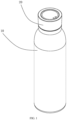
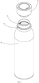
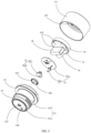
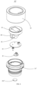
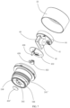
- an intelligent measurement cup of the present invention comprises a cup body 10 and a cup cover 20 detachably connected with the cup body 10.
- the cup body 10 is cylindrical, and a space is formed in the cup body for holding objects, especially liquid drinks such as water, milk and fruit juice.
- a top portion of the cup body 10 is shrunk to form a connecting portion 12 with a smaller caliber for being connected with the cup cover 20.
- a screw thread 14 is formed on an inner surface of the connecting portion 12, and screwed with the cup body 10.
- the cup body 10 has a heat insulation structure, which has a good heat preservation effect on the liquid in the cup for a certain period of time.
- the cup body 10 has an inner and outer double layer heat insulation structure, a gap is formed between inner and outer double layers, and the gap may be vacuum or filled with a heat insulation material, which effectively reduces heat transfer from inside to outside, thus achieving a heat insulation effect.
- a heat insulation material layer may also be formed on a wall surface of the cup body 10, so as to further reduce the heat transfer, thus achieving a heat preservation function.
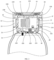
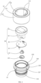
- the cup cover 20 comprises an outer cover 22, an inner cover 24 connected in the outer cover 22, and an electronic module 26 arranged in the inner cover 24.
- the outer cover 22 has an inverted U-shaped cross section, and comprises a top wall 221 and a side wall 223 extending downwards from an edge of the top wall 221.
- the inner cover 24 has a U-shaped cross section, and comprises a bottom plate 241 and a side plate 243 extending upwards from an edge of the bottom plate 241.
- An outer diameter of the side plate 243 of the inner cover 24 is smaller than an inner diameter of the side wall 223 of the outer cover 22, and a gap 23 is formed between the side plate and the side wall in a radial direction.
- a top portion of the side plate 243 extends outwards in a radial direction to form an annular fixing portion 245, and the annular fixing portion 245 is overlapped below the top wall 221 of the outer cover 22 and fixedly connected with the top wall of the outer cover.
- corresponding fixing holes 247 and 227 are formed in edges of the fixing portion 245 and the top wall 221, and fixing members such as screws penetrate into the fixing holes 247 and 227 to fixedly connect the inner cover 24 in the outer cover 22.
- An opening is formed in a center of the outer cover 22, a lens 225 is arranged at the opening, and the lens 225 is directly oriented to the electronic module 26 in the inner cover 24, which is convenient for a user to read relevant information displayed by the electronic module 26.
- an inner edge of the fixing portion 245 of the inner cover 24 extends upwards to form an annular lower positioning portion 249, and the lower positioning portion 249 is inserted into the opening of the outer cover 22 and abuts against a lower side of the lens 225.
- An inner edge of the top wall 221 of the outer cover 22 extends inwards in a radial direction to form an annular upper positioning portion 229, and the upper positioning portion 229 abuts against an upper side of the lens 225. Therefore, the lens 225 is clamped between the inner cover 24 and the outer cover 22 through the upper and lower positioning portions 229 and 249.
- an edge of the lens 225 protrudes downwards to form a ring flange 228, a ring groove 248 is formed on the positioning portion 249 of the inner cover 24, and the ring flange 228 of the lens 225 is connected into the ring groove 248 to form preliminary positioning.
- the ring groove 248 is internally provided with a sealing ring 30, which forms a sealed connection between the lens 225 and the inner cover 24.
- the ring flange 228 may also be formed on the inner cover 24, and correspondingly, the ring groove 248 may also be formed on the lens 225.
- the outer cover 22 is covered on the connecting portion 12 of the cup body 10 and the inner cover 24 is inserted into the connecting portion 12.
- the connecting portion 12 is inserted into the gap 23 between the side plate 243 and the side wall 223.
- a screw thread 244 is formed on an outer surface of the side plate 243, and the screw thread 244 is matched with the screw thread 14 at the connecting portion 12 of the cup body 10.
- the inner cover 24 may be screwed on the cup body 10 by rotating (usually in a clockwise direction) the cup cover 20. When the cup cover 20 needs to be removed, only the cup cover 20 is rotated in an opposite direction.
- the top portion and the bottom portion of the side plate 243 are sleeved with sealing members 32 and 34 respectively.
- the sealing member 32 at the top portion of the side plate 243 is sandwiched between the side plate 243 and the side wall 223 and the sealing member 34 at the bottom portion is sandwiched between the side plate 243 and the connecting portion 12, so that sealed connections are formed between the outer cover 22 and the inner cover 24 and between the inner cover 24 and the cup body 10, thus avoiding leakage caused by shaking and toppling of the cup.
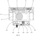
- the electronic module 26 comprises a battery 40, a main control circuit board 41 connected with the battery 40, and a plurality of functional units connected with the main control circuit board 41, such as a laser detection unit 42, a temperature detection unit 43, a display unit 44 and a voice unit 45.
- the battery 40 serves as a power supply for the whole cup, and is preferably a rechargeable battery.
- the main control circuit board 41 is configured for receiving data of the detection units 42 and 43 and informing the user by voice and/or text, such as broadcasting to the user through the voice unit 45, or displaying to the user through the display unit 44.
- a charging circuit connected with the battery 40 and charging pins 410 for being connected with an external power supply are formed on the main control circuit board 41.
- magnets 412 are embedded in the top wall 221 of the cup cover 20, and the magnets 412 are connected with the charging pins 410 in one-to-one correspondence to form charging heads of the cup of the present invention.
- the main control circuit board 41 is also provided with a Bluetooth module, which may perform wireless data transmission with other electronic devices, such as a mobile phone and a tablet computer.
- the laser detection unit 42 comprises a laser probe 420 and a first circuit board 422 electrically connected with the laser probe 420.
- the laser probe 420 is arranged towards the cup body 10, and a through hole 242 directly oriented to the laser probe 420 is correspondingly formed in a center of the bottom plate 241 of the inner cover 24.
- a shielding sheet 424 is covered below the laser probe 420, which has a scattering effect on light emitted by the laser probe.
- a mounting base 46 is also formed on the bottom plate 241 of the inner cover 24, and the mounting base 46 is arranged around the through hole 242 for fixing the laser detection unit 42.
- the shielding sheet 424 is made of a transparent material, is located at one side of the first circuit board 422 oriented to the cup body 10, and covers the laser probe 420.
- the laser probe 420 is arranged corresponding to a position of the through hole 242, and a part of the shielding sheet 424 corresponding to the laser probe 420 protrudes into the through hole 242 to form a cover-like shielding portion 426.
- the shielding portion 426 is closely matched with the through hole 242 to close the through hole 242, which may isolate the electronic module 26.
- the laser probe 420 When in use, the laser probe 420 emits laser light towards the cup body 10 and receives feedback photons, scattering may be formed when the emitted laser light encounters the shielding portion 426, and a single emission direction of the laser light is changed, so that the laser light can be divergently emitted into the cup body 10. Therefore, there can be more feedback photons, and spectra reflected by different emitting media are different. Therefore, the first circuit board 422 calculates, analyzes and judges a liquid level in the cup body 10 and composition of the liquid in the cup body 10 according to the feedback photons of the laser probe 420.
- the first circuit board 422 is integrated with a micro spectrum sensor chip AS7341, and the AS7341 is an 11-channel device, wherein 8 channels cover 8 equidistant parts in a visible spectrum, and there are also a near-infrared light channel, a pure channel and a channel dedicated to detecting typical ambient light flicker, so that a spectral characteristic of a light source or a reflective surface can be measured very accurately.
- AS7341 is an 11-channel device, wherein 8 channels cover 8 equidistant parts in a visible spectrum, and there are also a near-infrared light channel, a pure channel and a channel dedicated to detecting typical ambient light flicker, so that a spectral characteristic of a light source or a reflective surface can be measured very accurately.
- the light is divergently emitted into the cup body 10, so that the laser detection unit 42 has enough feedback photons to accurately judge conditions of the liquid in the cup body 10.
- the height of the liquid in the cup body 10 may be calculated according to a distance of the feedback photons, which means that an allowance of the liquid in the cup body 10 may be calculated.
- the composition of the liquid in the cup body 10 may be analyzed to judge which liquid it is and whether the liquid goes bad or not.
- the shielding sheet 424 when the dirt does not completely cover the shielding sheet 424, a certain amount of laser light may still be divergently emitted into the cup body 10 after being scattered by the shielding sheet 424, thus ensuring an accuracy of measurement.
- the laser light turns back at the shielding sheet 424, and at the moment, the reflection distance of the laser photons is very short, so that whether the shielding sheet 424 needs to be cleaned may be judged by a reflection stroke of the laser light.
- the temperature detection unit 43 comprises a temperature probe 430 and a second circuit board 432 connected with the temperature probe 430.
- the temperature probe 430 is arranged towards an inside of the cup body 10, and correspondingly, a through hole 246 is formed in the bottom plate 241 of the inner cover 24 for the temperature probe 430 to penetrate through.
- the temperature probe 430 senses a temperature in the cup body 10 and feeds back a result to the second circuit board 432 for processing.
- a first step 47 and a second step 48 are formed on an inner surface of the side plate 243 of the inner cover 24.
- the first step 47 is formed at a top end of the side plate 243 for fixing the main control circuit board 41.
- the second step 48 is close to a bottom end of the side plate 243 for fixing the second circuit board 432.
- the main control circuit board 41 may be electrically connected with the first and second circuit boards 422 and 432 through a connector and a leading wire, and according to detection results of the temperature detection unit 43 and the laser detection unit 42, the display unit 44 and the voice unit 45 are controlled to output corresponding information.
- the display unit 44 is arranged towards the lens 225 of the outer cover 22, and directly displays the detection results, such as the allowance of the liquid, the composition of the liquid and the temperature of the liquid, to the user by the text under an action of the main control circuit board 41. Certainly, the display unit 44 may also display other information, such as date and time.
- the voice unit 45 may be a sound pickup such as a loudspeaker, or a sound generator such as a speaker and a buzzer, which informs the user of the detection results by voice or warning under the action of the main control circuit board 41, such as informing of the type, the temperature and the allowance of the liquid in the cup body 10 by voice; or when the shielding sheet 424 needs to be cleaned, an alarm is given to remind the user to clean, or when the liquid in the cup body 10 goes bad, an alarm is given to remind the user not to drink.
- the voice unit 45 may also broadcast or warn of other information, such as on-time alarm and charging warning, or may also receive an external voice instruction.
- the voice unit 45 and the battery 40 are arranged between the main control circuit board 41 and the second circuit board 432, and the space in the inner cover 24 is reasonably utilized.
- the cup cover 20 is provided with a sound outlet hole for the voice unit 45 to output voice.
- the display unit 44 is located above the main control circuit board 41, and directly oriented to the lens 225 of the outer cover 22.
- the charging pins 410 penetrate through a housing base of the display unit 44 and are connected with the magnets 412.
- the units of the electronic module 26 are reasonably arranged in the inner cover 24, so as to ensure that the functional units may not conflict with each other, and also facilitate routing and connection between the functional units.
- FIG. 6 to FIG. 8 show a cup cover 20' of the intelligent measurement cup according to another embodiment of the present invention, which is mainly different from that of the previous embodiment in a shielding sheet 424'.
- the laser probe 420 is accommodated in the inner cover 24', and the shielding sheet 424' is arranged at one side of a bottom plate 241' of the inner cover 24' oriented to the cup body 10.
- the through hole 242 corresponding to the laser probe 420 is formed in a center of the bottom plate 241', and the groove 248 surrounding the through hole 242 is formed at one side of the bottom plate 241' oriented to the cup body 10.
- the shielding sheet 424' is a flat circular sheet, which is embedded in the groove 248 and covers the laser probe 420 at the through hole 242.
- an edge of the shielding sheet 424' and the bottom plate 241' are integrally connected by ultrasonic welding.
- the shielding sheet 424' may be partially painted black to reduce light transmission.
- the shielding sheet 424' has a scattering effect on the laser light emitted by the laser probe 420, and enough feedback photons are formed, so as to accurately judge the conditions of the liquid in the cup body 10, comprising the allowance of the liquid, the type of the liquid, and whether the liquid goes bad or not.
Landscapes
- Physics & Mathematics (AREA)
- General Physics & Mathematics (AREA)
- Electromagnetism (AREA)
- Fluid Mechanics (AREA)
- Thermal Sciences (AREA)
- Chemical & Material Sciences (AREA)
- Health & Medical Sciences (AREA)
- Life Sciences & Earth Sciences (AREA)
- Analytical Chemistry (AREA)
- Biochemistry (AREA)
- General Health & Medical Sciences (AREA)
- Immunology (AREA)
- Pathology (AREA)
- Engineering & Computer Science (AREA)
- Signal Processing (AREA)
- Spectroscopy & Molecular Physics (AREA)
- Table Devices Or Equipment (AREA)
- Investigating Or Analysing Materials By Optical Means (AREA)
Claims (10)
- - Intelligenter Messbecher, umfassend einen Becherkörper (10) und eine Becherabdeckung (20), die den Becherkörper (10) abdeckt, wobei die Becherabdeckung (20) im Inneren mit einem elektronischen Modul (26) ausgestattet ist, das elektronische Modul (26) eine Batterie (40), eine Hauptsteuerplatine (41) umfasst, die elektrisch mit der Batterie (40) verbunden ist, gekennzeichnet durch eine Lasernachweiseinheit (42), die elektrisch mit der Hauptsteuerplatine (41) verbunden ist, die Lasernachweiseinheit (42) eine Lasersonde (420) und ein transparentes Abschirmblech (424) umfasst, das die Lasersonde (420) abdeckt, wobei die Lasersonde (420) hin zu einer Seite angeordnet ist, auf der sich der Becherkörper (10) befindet, ein Durchgangsloch (242), das der Lasersonde (420) entspricht, in der Becherabdeckung (20) gebildet ist, damit Licht der Lasersonde (420) hindurchdringt und Laserlicht, emittiert durch die Lasersonde (420) durch das Abschirmblech (424) strömt und dann in den Becherkörper (10) auf streuende Weise emittiert wird.
- - Intelligenter Messbecher nach Anspruch 1, weiter umfassend eine Temperaturnachweiseinheit (43), die mit der Hauptsteuerplatine (41) verbunden ist, wobei die Temperaturnachweiseinheit (43) eine Temperatursonde (430) umfasst und die Temperatursonde (430) durch die Becherabdeckung (20) eindringt und sich in den Becherkörper (10) erstreckt.
- - Intelligenter Messbecher nach Anspruch 1, wobei die Batterie (40) eine wiederaufladbare Batterie (40) ist, Ladestifte (410), um mit einer externen Stromversorgung verbunden zu werden, auf der Hauptsteuerplatine (41) bereitgestellt sind, Magnete (412) in der Becherabdeckung (20) eingebettet sind und die Magnete (412) mit den Ladestiften (410) verbunden sind.
- - Intelligenter Messbecher nach Anspruch 1, weiter umfassend eine Anzeigeeinheit (44), die mit der Hauptsteuerplatine (41) verbunden ist, wobei eine Linse (225), die direkt auf die Anzeigeeinheit (44) gerichtet ist, auf einem oberen Abschnitt der Becherabdeckung (20) gebildet ist.
- - Intelligenter Messbecher nach Anspruch 1, weiter umfassend eine Toneinheit (45), die mit der Hauptsteuerplatine (41) verbunden ist, wobei die Toneinheit (45) eine Schallaufnahme oder ein Schallgenerator ist.
- - Intelligenter Messbecher nach einem der Ansprüche 1 bis 5, wobei die Becherabdeckung (20) eine äußere Abdeckung (22) und eine innere Abdeckung (24) umfasst, die in der äußeren Abdeckung (22) verbunden ist, das elektronische Modul (26) in der inneren Abdeckung (24) angeordnet ist, die innere Abdeckung (24) eine untere Platte (241) und eine Seitenplatte (243) umfasst, die sich von einer Kante der unteren Platte (241) nach oben erstreckt, das Durchgangsloch (242), das der Lasersonde (420) entspricht, in der unteren Platte (241) gebildet ist und das Abschirmblech (424) entsprechend dem Durchgangsloch (242) angeordnet ist und die Lasersonde (420) abdeckt.
- - Intelligenter Messbecher nach Anspruch 6, wobei das Abschirmblech (424) an einer Seite der unteren Platte (241) angeordnet ist, die vom Becherkörper (10) weg gerichtet ist, das Abschirmblech (424) einen Abschirmabschnitt (426) umfasst, der in das Durchgangsloch (242) vorspringt, und der Abschirmabschnitt (426) die Lasersonde (420) abdeckt.
- - Intelligenter Messbecher nach Anspruch 6, wobei das Abschirmblech (424) an einer Seite der unteren Platte (241) angeordnet ist, die zum Becherkörper (10) gerichtet ist, und eine Nut (248) auf einer Seite der unteren Platte (241) gebildet ist, die zum Becherkörper (10) gerichtet ist, um das Abschirmblech (424) aufzunehmen.
- - Intelligenter Messbecher nach Anspruch 6, wobei die äußere Abdeckung (22) eine obere Wand (221) und eine Seitenwand (223) umfasst, die sich von einer Kante der oberen Wand (221) nach unten erstreckt, die Seitenwand (223) die Seitenplatte (243) umgibt und ein Zwischenraum (23) zwischen der Seitenwand (223) und der Seitenplatte (243) gebildet ist, um mit dem Becherkörper (10) verbunden zu sein, und die Seitenplatte (243) in den Becherkörper (10) eingeführt und mit dem Becherkörper (10) verschraubt ist.
- - Intelligenter Messbecher nach Anspruch 9, wobei eine Öffnung in einer Mitte der oberen Wand (221) gebildet ist, die Linse (225) an der Öffnung angeordnet ist, eine innere Kante der oberen Wand (221) nach innen in eine radiale Richtung vorspringt, um einen oberen Positionierungsabschnitt (229) zu bilden, der obere Abschnitt der Seitenplatte (243) in die Öffnung vorsteht, um einen unteren Positionierungsabschnitt (249) zu bilden, die Linse (225) zwischen den oberen Positionierungsabschnitt (229) und den unteren Positionierungsabschnitt (249) geklemmt ist, eine Ringnut (248) auf einer der Linsen (225) und der untere Positionierungsabschnitt (249) gebildet ist und ein Ringflansch (228) auf der anderen gebildet ist und der Ringflansch (228) mit der Ringnut (248) verbunden ist.
Applications Claiming Priority (2)
| Application Number | Priority Date | Filing Date | Title |
|---|---|---|---|
| CN202010410109.8A CN111513525A (zh) | 2020-05-15 | 2020-05-15 | 一种智能测量杯子 |
| PCT/CN2020/093742 WO2021227144A1 (zh) | 2020-05-15 | 2020-06-01 | 一种智能测量杯子 |
Publications (4)
| Publication Number | Publication Date |
|---|---|
| EP4023112A1 EP4023112A1 (de) | 2022-07-06 |
| EP4023112A4 EP4023112A4 (de) | 2023-09-27 |
| EP4023112B1 true EP4023112B1 (de) | 2024-05-22 |
| EP4023112C0 EP4023112C0 (de) | 2024-05-22 |
Family
ID=71912497
Family Applications (1)
| Application Number | Title | Priority Date | Filing Date |
|---|---|---|---|
| EP20935283.0A Active EP4023112B1 (de) | 2020-05-15 | 2020-06-01 | Intelligenter messbecher |
Country Status (4)
| Country | Link |
|---|---|
| US (1) | US12055429B2 (de) |
| EP (1) | EP4023112B1 (de) |
| CN (1) | CN111513525A (de) |
| WO (1) | WO2021227144A1 (de) |
Families Citing this family (8)
| Publication number | Priority date | Publication date | Assignee | Title |
|---|---|---|---|---|
| DE102022202131A1 (de) * | 2022-03-02 | 2023-09-07 | Skf Lubrication Systems Germany Gmbh | Füllstandsmessanordnung |
| WO2023229542A1 (en) * | 2022-05-23 | 2023-11-30 | Amazing Camel Yazilim Ve Mühendislik Tic. A.Ş. | Smart bottle with beverage consumption assistant |
| CN115165016A (zh) * | 2022-07-06 | 2022-10-11 | 广东吉米有品智能科技有限公司 | 一种水杯饮水量计算方法 |
| US20240102842A1 (en) * | 2022-09-28 | 2024-03-28 | Huan Zheng | Laser fuel measurement device |
| CN220001432U (zh) * | 2023-02-17 | 2023-11-14 | 小水怪(深圳)智能科技有限公司 | 一种测量水杯 |
| US12005408B1 (en) | 2023-04-14 | 2024-06-11 | Sharkninja Operating Llc | Mixing funnel |
| WO2024254837A1 (en) | 2023-06-16 | 2024-12-19 | Sharkninja Operating Llc | Carbonation mixing nozzles |
| DE102023118499A1 (de) | 2023-07-12 | 2025-01-16 | Sensorentechnologie Gettorf Gmbh | Vorrichtung zur Herstellung eines Getränks durch Aufbereitung eines Schüttguts mit einer Flüssigkeit |
Family Cites Families (17)
| Publication number | Priority date | Publication date | Assignee | Title |
|---|---|---|---|---|
| JP2012073033A (ja) * | 2010-09-27 | 2012-04-12 | Panasonic Electric Works Co Ltd | 赤外線アレイセンサを用いた水位検出装置 |
| CN104643829B (zh) * | 2015-03-17 | 2016-09-07 | 巨鲸网络科技(上海)有限公司 | 智能水杯、智能水杯的饮水量检测方法及其系统 |
| CN104757851B (zh) * | 2015-04-17 | 2016-05-11 | 惠州鑫润通实业有限公司 | 一种杯盖及智能水杯 |
| US9945711B2 (en) * | 2016-02-05 | 2018-04-17 | Pepsico, Inc. | Infrared sensor assembly for ingredient level detection in beverage dispensers |
| DE102016215615A1 (de) * | 2016-08-19 | 2018-02-22 | Belenus Verwaltungsgesellschaft Mbh | System zum Überwachen einer Flüssigkeitsaufnahme eines Benutzers und Verfahren zum Betrieb des Systems |
| CN206261375U (zh) * | 2016-09-02 | 2017-06-20 | 汉华数字饮水器具科技(深圳)有限公司 | 一种智能检测水杯 |
| CN108309062B (zh) * | 2017-01-18 | 2022-02-11 | 佛山市顺德区美的电热电器制造有限公司 | 储物装置和烹饪器具 |
| CN106724604B (zh) * | 2017-03-21 | 2019-02-22 | 深圳汉华科技股份有限公司 | 一种多功能智能水杯及其健康管理系统 |
| CN207444739U (zh) * | 2017-04-13 | 2018-06-05 | 深圳市瑞丰光电紫光技术有限公司 | 一种紫外杀菌装置、杯盖及水杯 |
| CN107416312A (zh) * | 2017-04-24 | 2017-12-01 | 深圳市赛亿科技开发有限公司 | 一种检测食用油品质的油壶及检测方法 |
| EP3434151B1 (de) * | 2017-07-24 | 2022-10-19 | Riprup Company S.A. | Intelligente flasche |
| CN108685429A (zh) * | 2018-05-25 | 2018-10-23 | 合肥智慧龙图腾知识产权股份有限公司 | 一种具有手势识别功能的智能水杯 |
| CN109077572A (zh) * | 2018-08-17 | 2018-12-25 | 厦门市三安光电科技有限公司 | 一种紫外杀菌杯结构 |
| CN209563941U (zh) * | 2018-09-29 | 2019-11-01 | 小水怪(深圳)智能科技有限公司 | 一种智能水杯 |
| CN209518675U (zh) * | 2018-11-29 | 2019-10-22 | 九阳股份有限公司 | 一种带液位检测的茶壶 |
| CN209610709U (zh) * | 2018-12-29 | 2019-11-12 | 深圳麦开网络技术有限公司 | 一种杯盖及水杯 |
| CN212591475U (zh) * | 2020-05-15 | 2021-02-26 | 小水怪(深圳)智能科技有限公司 | 一种智能测量杯子 |
-
2020
- 2020-05-15 CN CN202010410109.8A patent/CN111513525A/zh active Pending
- 2020-06-01 EP EP20935283.0A patent/EP4023112B1/de active Active
- 2020-06-01 WO PCT/CN2020/093742 patent/WO2021227144A1/zh not_active Ceased
- 2020-06-01 US US17/629,786 patent/US12055429B2/en active Active
Also Published As
| Publication number | Publication date |
|---|---|
| EP4023112A1 (de) | 2022-07-06 |
| US20220268617A1 (en) | 2022-08-25 |
| US12055429B2 (en) | 2024-08-06 |
| EP4023112C0 (de) | 2024-05-22 |
| WO2021227144A1 (zh) | 2021-11-18 |
| EP4023112A4 (de) | 2023-09-27 |
| CN111513525A (zh) | 2020-08-11 |
Similar Documents
| Publication | Publication Date | Title |
|---|---|---|
| EP4023112B1 (de) | Intelligenter messbecher | |
| US12222287B2 (en) | Universal rapid diagnostic test reader with trans-visual sensitivity | |
| CN106724604B (zh) | 一种多功能智能水杯及其健康管理系统 | |
| US20180000362A1 (en) | Biological information measuring module and biological information measuring apparatus | |
| US20210156791A1 (en) | Residual toxicant detection device | |
| CN212591475U (zh) | 一种智能测量杯子 | |
| US8090260B2 (en) | Light source and detecting device thereof | |
| CN110945375A (zh) | 传感器单元和空调机 | |
| CN110290304B (zh) | 深度相机及终端 | |
| CN211824468U (zh) | 一种光电传感器 | |
| CN217309787U (zh) | 水杯 | |
| CN212846810U (zh) | 定位显示设备 | |
| CN113075267A (zh) | 液体浓度检测装置 | |
| CN113310948A (zh) | 一种智能化快速测定菜肴食品营养含量的检测装置 | |
| CN222486930U (zh) | 一种带温度显示与饮水计量的杯盖及保温杯 | |
| CN221325613U (zh) | 红外检测装置 | |
| CN221105467U (zh) | 一种带灯光的恒温杯 | |
| KR102760828B1 (ko) | 에어로졸 생성장치 | |
| KR20250046707A (ko) | 비파괴 당도 측정기 | |
| CN211956659U (zh) | 声光警报器 | |
| CN223797006U (zh) | 一种毫米波久坐提醒器 | |
| CN215765950U (zh) | 具有灯光指示的气味检测装置、冰箱 | |
| CN215077304U (zh) | 水杯 | |
| CN215868136U (zh) | 一种防近视的检测装置、保护壳体及电子设备 | |
| KR20250046711A (ko) | 비파괴 당도 측정기용 광학 모듈 |
Legal Events
| Date | Code | Title | Description |
|---|---|---|---|
| STAA | Information on the status of an ep patent application or granted ep patent |
Free format text: STATUS: THE INTERNATIONAL PUBLICATION HAS BEEN MADE |
|
| PUAI | Public reference made under article 153(3) epc to a published international application that has entered the european phase |
Free format text: ORIGINAL CODE: 0009012 |
|
| STAA | Information on the status of an ep patent application or granted ep patent |
Free format text: STATUS: REQUEST FOR EXAMINATION WAS MADE |
|
| 17P | Request for examination filed |
Effective date: 20220324 |
|
| AK | Designated contracting states |
Kind code of ref document: A1 Designated state(s): AL AT BE BG CH CY CZ DE DK EE ES FI FR GB GR HR HU IE IS IT LI LT LU LV MC MK MT NL NO PL PT RO RS SE SI SK SM TR |
|
| DAV | Request for validation of the european patent (deleted) | ||
| DAX | Request for extension of the european patent (deleted) | ||
| A4 | Supplementary search report drawn up and despatched |
Effective date: 20230829 |
|
| RIC1 | Information provided on ipc code assigned before grant |
Ipc: G01F 23/292 20060101ALI20230823BHEP Ipc: A47G 23/16 20060101ALI20230823BHEP Ipc: A47G 19/22 20060101AFI20230823BHEP |
|
| GRAP | Despatch of communication of intention to grant a patent |
Free format text: ORIGINAL CODE: EPIDOSNIGR1 |
|
| STAA | Information on the status of an ep patent application or granted ep patent |
Free format text: STATUS: GRANT OF PATENT IS INTENDED |
|
| RIC1 | Information provided on ipc code assigned before grant |
Ipc: G01N 21/31 20060101ALI20240201BHEP Ipc: G01N 21/03 20060101ALI20240201BHEP Ipc: G01K 1/14 20210101ALI20240201BHEP Ipc: G01F 23/292 20060101ALI20240201BHEP Ipc: A47G 23/16 20060101ALI20240201BHEP Ipc: A47G 19/22 20060101AFI20240201BHEP |
|
| INTG | Intention to grant announced |
Effective date: 20240215 |
|
| GRAS | Grant fee paid |
Free format text: ORIGINAL CODE: EPIDOSNIGR3 |
|
| GRAA | (expected) grant |
Free format text: ORIGINAL CODE: 0009210 |
|
| STAA | Information on the status of an ep patent application or granted ep patent |
Free format text: STATUS: THE PATENT HAS BEEN GRANTED |
|
| AK | Designated contracting states |
Kind code of ref document: B1 Designated state(s): AL AT BE BG CH CY CZ DE DK EE ES FI FR GB GR HR HU IE IS IT LI LT LU LV MC MK MT NL NO PL PT RO RS SE SI SK SM TR |
|
| REG | Reference to a national code |
Ref country code: GB Ref legal event code: FG4D |
|
| REG | Reference to a national code |
Ref country code: CH Ref legal event code: EP |
|
| REG | Reference to a national code |
Ref country code: DE Ref legal event code: R096 Ref document number: 602020031474 Country of ref document: DE |
|
| REG | Reference to a national code |
Ref country code: IE Ref legal event code: FG4D |
|
| U01 | Request for unitary effect filed |
Effective date: 20240619 |
|
| U07 | Unitary effect registered |
Designated state(s): AT BE BG DE DK EE FI FR IT LT LU LV MT NL PT SE SI Effective date: 20240626 |
|
| U20 | Renewal fee for the european patent with unitary effect paid |
Year of fee payment: 5 Effective date: 20240729 |
|
| PG25 | Lapsed in a contracting state [announced via postgrant information from national office to epo] |
Ref country code: IS Free format text: LAPSE BECAUSE OF FAILURE TO SUBMIT A TRANSLATION OF THE DESCRIPTION OR TO PAY THE FEE WITHIN THE PRESCRIBED TIME-LIMIT Effective date: 20240922 |
|
| PG25 | Lapsed in a contracting state [announced via postgrant information from national office to epo] |
Ref country code: HR Free format text: LAPSE BECAUSE OF FAILURE TO SUBMIT A TRANSLATION OF THE DESCRIPTION OR TO PAY THE FEE WITHIN THE PRESCRIBED TIME-LIMIT Effective date: 20240522 |
|
| PG25 | Lapsed in a contracting state [announced via postgrant information from national office to epo] |
Ref country code: GR Free format text: LAPSE BECAUSE OF FAILURE TO SUBMIT A TRANSLATION OF THE DESCRIPTION OR TO PAY THE FEE WITHIN THE PRESCRIBED TIME-LIMIT Effective date: 20240823 |
|
| PG25 | Lapsed in a contracting state [announced via postgrant information from national office to epo] |
Ref country code: ES Free format text: LAPSE BECAUSE OF FAILURE TO SUBMIT A TRANSLATION OF THE DESCRIPTION OR TO PAY THE FEE WITHIN THE PRESCRIBED TIME-LIMIT Effective date: 20240522 |
|
| PG25 | Lapsed in a contracting state [announced via postgrant information from national office to epo] |
Ref country code: PL Free format text: LAPSE BECAUSE OF FAILURE TO SUBMIT A TRANSLATION OF THE DESCRIPTION OR TO PAY THE FEE WITHIN THE PRESCRIBED TIME-LIMIT Effective date: 20240522 |
|
| PG25 | Lapsed in a contracting state [announced via postgrant information from national office to epo] |
Ref country code: PL Free format text: LAPSE BECAUSE OF FAILURE TO SUBMIT A TRANSLATION OF THE DESCRIPTION OR TO PAY THE FEE WITHIN THE PRESCRIBED TIME-LIMIT Effective date: 20240522 Ref country code: NO Free format text: LAPSE BECAUSE OF FAILURE TO SUBMIT A TRANSLATION OF THE DESCRIPTION OR TO PAY THE FEE WITHIN THE PRESCRIBED TIME-LIMIT Effective date: 20240822 Ref country code: IS Free format text: LAPSE BECAUSE OF FAILURE TO SUBMIT A TRANSLATION OF THE DESCRIPTION OR TO PAY THE FEE WITHIN THE PRESCRIBED TIME-LIMIT Effective date: 20240922 Ref country code: HR Free format text: LAPSE BECAUSE OF FAILURE TO SUBMIT A TRANSLATION OF THE DESCRIPTION OR TO PAY THE FEE WITHIN THE PRESCRIBED TIME-LIMIT Effective date: 20240522 Ref country code: GR Free format text: LAPSE BECAUSE OF FAILURE TO SUBMIT A TRANSLATION OF THE DESCRIPTION OR TO PAY THE FEE WITHIN THE PRESCRIBED TIME-LIMIT Effective date: 20240823 Ref country code: ES Free format text: LAPSE BECAUSE OF FAILURE TO SUBMIT A TRANSLATION OF THE DESCRIPTION OR TO PAY THE FEE WITHIN THE PRESCRIBED TIME-LIMIT Effective date: 20240522 Ref country code: RS Free format text: LAPSE BECAUSE OF FAILURE TO SUBMIT A TRANSLATION OF THE DESCRIPTION OR TO PAY THE FEE WITHIN THE PRESCRIBED TIME-LIMIT Effective date: 20240822 |
|
| PG25 | Lapsed in a contracting state [announced via postgrant information from national office to epo] |
Ref country code: CZ Free format text: LAPSE BECAUSE OF FAILURE TO SUBMIT A TRANSLATION OF THE DESCRIPTION OR TO PAY THE FEE WITHIN THE PRESCRIBED TIME-LIMIT Effective date: 20240522 |
|
| PG25 | Lapsed in a contracting state [announced via postgrant information from national office to epo] |
Ref country code: RO Free format text: LAPSE BECAUSE OF FAILURE TO SUBMIT A TRANSLATION OF THE DESCRIPTION OR TO PAY THE FEE WITHIN THE PRESCRIBED TIME-LIMIT Effective date: 20240522 Ref country code: SK Free format text: LAPSE BECAUSE OF FAILURE TO SUBMIT A TRANSLATION OF THE DESCRIPTION OR TO PAY THE FEE WITHIN THE PRESCRIBED TIME-LIMIT Effective date: 20240522 |
|
| PG25 | Lapsed in a contracting state [announced via postgrant information from national office to epo] |
Ref country code: SK Free format text: LAPSE BECAUSE OF FAILURE TO SUBMIT A TRANSLATION OF THE DESCRIPTION OR TO PAY THE FEE WITHIN THE PRESCRIBED TIME-LIMIT Effective date: 20240522 Ref country code: RO Free format text: LAPSE BECAUSE OF FAILURE TO SUBMIT A TRANSLATION OF THE DESCRIPTION OR TO PAY THE FEE WITHIN THE PRESCRIBED TIME-LIMIT Effective date: 20240522 Ref country code: CZ Free format text: LAPSE BECAUSE OF FAILURE TO SUBMIT A TRANSLATION OF THE DESCRIPTION OR TO PAY THE FEE WITHIN THE PRESCRIBED TIME-LIMIT Effective date: 20240522 |
|
| REG | Reference to a national code |
Ref country code: CH Ref legal event code: PL |
|
| PG25 | Lapsed in a contracting state [announced via postgrant information from national office to epo] |
Ref country code: MC Free format text: LAPSE BECAUSE OF FAILURE TO SUBMIT A TRANSLATION OF THE DESCRIPTION OR TO PAY THE FEE WITHIN THE PRESCRIBED TIME-LIMIT Effective date: 20240522 |
|
| REG | Reference to a national code |
Ref country code: DE Ref legal event code: R097 Ref document number: 602020031474 Country of ref document: DE |
|
| PLBE | No opposition filed within time limit |
Free format text: ORIGINAL CODE: 0009261 |
|
| STAA | Information on the status of an ep patent application or granted ep patent |
Free format text: STATUS: NO OPPOSITION FILED WITHIN TIME LIMIT |
|
| PG25 | Lapsed in a contracting state [announced via postgrant information from national office to epo] |
Ref country code: IE Free format text: LAPSE BECAUSE OF NON-PAYMENT OF DUE FEES Effective date: 20240601 |
|
| PG25 | Lapsed in a contracting state [announced via postgrant information from national office to epo] |
Ref country code: CH Free format text: LAPSE BECAUSE OF NON-PAYMENT OF DUE FEES Effective date: 20240630 |
|
| 26N | No opposition filed |
Effective date: 20250225 |
|
| U20 | Renewal fee for the european patent with unitary effect paid |
Year of fee payment: 6 Effective date: 20250528 |
|
| PGFP | Annual fee paid to national office [announced via postgrant information from national office to epo] |
Ref country code: GB Payment date: 20250625 Year of fee payment: 6 |
|
| PG25 | Lapsed in a contracting state [announced via postgrant information from national office to epo] |
Ref country code: CY Free format text: LAPSE BECAUSE OF FAILURE TO SUBMIT A TRANSLATION OF THE DESCRIPTION OR TO PAY THE FEE WITHIN THE PRESCRIBED TIME-LIMIT; INVALID AB INITIO Effective date: 20200601 |
|
| PG25 | Lapsed in a contracting state [announced via postgrant information from national office to epo] |
Ref country code: SM Free format text: LAPSE BECAUSE OF FAILURE TO SUBMIT A TRANSLATION OF THE DESCRIPTION OR TO PAY THE FEE WITHIN THE PRESCRIBED TIME-LIMIT; INVALID AB INITIO Effective date: 20200601 |