EP4021800B1 - Verfahren zum herstellen eines torsionskasten für eine struktur eines flugzeugs sowie ein torsionskasten für eine struktur eines flugzeugs - Google Patents
Verfahren zum herstellen eines torsionskasten für eine struktur eines flugzeugs sowie ein torsionskasten für eine struktur eines flugzeugs Download PDFInfo
- Publication number
- EP4021800B1 EP4021800B1 EP20820269.7A EP20820269A EP4021800B1 EP 4021800 B1 EP4021800 B1 EP 4021800B1 EP 20820269 A EP20820269 A EP 20820269A EP 4021800 B1 EP4021800 B1 EP 4021800B1
- Authority
- EP
- European Patent Office
- Prior art keywords
- stiffening elements
- base
- component
- stiffening
- torsion box
- Prior art date
- Legal status (The legal status is an assumption and is not a legal conclusion. Google has not performed a legal analysis and makes no representation as to the accuracy of the status listed.)
- Active
Links
Images

Classifications
-
- B—PERFORMING OPERATIONS; TRANSPORTING
- B64—AIRCRAFT; AVIATION; COSMONAUTICS
- B64C—AEROPLANES; HELICOPTERS
- B64C1/00—Fuselages; Constructional features common to fuselages, wings, stabilising surfaces or the like
- B64C1/06—Frames; Stringers; Longerons ; Fuselage sections
- B64C1/12—Construction or attachment of skin panels
-
- B—PERFORMING OPERATIONS; TRANSPORTING
- B29—WORKING OF PLASTICS; WORKING OF SUBSTANCES IN A PLASTIC STATE IN GENERAL
- B29D—PRODUCING PARTICULAR ARTICLES FROM PLASTICS OR FROM SUBSTANCES IN A PLASTIC STATE
- B29D24/00—Producing articles with hollow walls
- B29D24/002—Producing articles with hollow walls formed with structures, e.g. cores placed between two plates or sheets, e.g. partially filled
- B29D24/008—Producing articles with hollow walls formed with structures, e.g. cores placed between two plates or sheets, e.g. partially filled the structure having hollow ridges, ribs or cores
-
- B—PERFORMING OPERATIONS; TRANSPORTING
- B29—WORKING OF PLASTICS; WORKING OF SUBSTANCES IN A PLASTIC STATE IN GENERAL
- B29C—SHAPING OR JOINING OF PLASTICS; SHAPING OF MATERIAL IN A PLASTIC STATE, NOT OTHERWISE PROVIDED FOR; AFTER-TREATMENT OF THE SHAPED PRODUCTS, e.g. REPAIRING
- B29C65/00—Joining or sealing of preformed parts, e.g. welding of plastics materials; Apparatus therefor
- B29C65/02—Joining or sealing of preformed parts, e.g. welding of plastics materials; Apparatus therefor by heating, with or without pressure
- B29C65/022—Particular heating or welding methods not otherwise provided for
-
- B—PERFORMING OPERATIONS; TRANSPORTING
- B29—WORKING OF PLASTICS; WORKING OF SUBSTANCES IN A PLASTIC STATE IN GENERAL
- B29C—SHAPING OR JOINING OF PLASTICS; SHAPING OF MATERIAL IN A PLASTIC STATE, NOT OTHERWISE PROVIDED FOR; AFTER-TREATMENT OF THE SHAPED PRODUCTS, e.g. REPAIRING
- B29C65/00—Joining or sealing of preformed parts, e.g. welding of plastics materials; Apparatus therefor
- B29C65/48—Joining or sealing of preformed parts, e.g. welding of plastics materials; Apparatus therefor using adhesives, i.e. using supplementary joining material; solvent bonding
-
- B—PERFORMING OPERATIONS; TRANSPORTING
- B29—WORKING OF PLASTICS; WORKING OF SUBSTANCES IN A PLASTIC STATE IN GENERAL
- B29C—SHAPING OR JOINING OF PLASTICS; SHAPING OF MATERIAL IN A PLASTIC STATE, NOT OTHERWISE PROVIDED FOR; AFTER-TREATMENT OF THE SHAPED PRODUCTS, e.g. REPAIRING
- B29C65/00—Joining or sealing of preformed parts, e.g. welding of plastics materials; Apparatus therefor
- B29C65/56—Joining or sealing of preformed parts, e.g. welding of plastics materials; Apparatus therefor using mechanical means or mechanical connections, e.g. form-fits
- B29C65/60—Riveting or staking
-
- B—PERFORMING OPERATIONS; TRANSPORTING
- B64—AIRCRAFT; AVIATION; COSMONAUTICS
- B64C—AEROPLANES; HELICOPTERS
- B64C1/00—Fuselages; Constructional features common to fuselages, wings, stabilising surfaces or the like
- B64C1/06—Frames; Stringers; Longerons ; Fuselage sections
- B64C1/064—Stringers; Longerons
-
- B—PERFORMING OPERATIONS; TRANSPORTING
- B64—AIRCRAFT; AVIATION; COSMONAUTICS
- B64C—AEROPLANES; HELICOPTERS
- B64C1/00—Fuselages; Constructional features common to fuselages, wings, stabilising surfaces or the like
- B64C1/06—Frames; Stringers; Longerons ; Fuselage sections
- B64C1/065—Spars
-
- B—PERFORMING OPERATIONS; TRANSPORTING
- B64—AIRCRAFT; AVIATION; COSMONAUTICS
- B64C—AEROPLANES; HELICOPTERS
- B64C3/00—Wings
- B64C3/18—Spars; Ribs; Stringers
- B64C3/185—Spars
-
- B—PERFORMING OPERATIONS; TRANSPORTING
- B64—AIRCRAFT; AVIATION; COSMONAUTICS
- B64C—AEROPLANES; HELICOPTERS
- B64C3/00—Wings
- B64C3/18—Spars; Ribs; Stringers
- B64C3/187—Ribs
-
- B—PERFORMING OPERATIONS; TRANSPORTING
- B64—AIRCRAFT; AVIATION; COSMONAUTICS
- B64C—AEROPLANES; HELICOPTERS
- B64C3/00—Wings
- B64C3/20—Integral or sandwich constructions
-
- B—PERFORMING OPERATIONS; TRANSPORTING
- B64—AIRCRAFT; AVIATION; COSMONAUTICS
- B64C—AEROPLANES; HELICOPTERS
- B64C3/00—Wings
- B64C3/26—Construction, shape, or attachment of separate skins, e.g. panels
-
- B—PERFORMING OPERATIONS; TRANSPORTING
- B64—AIRCRAFT; AVIATION; COSMONAUTICS
- B64F—GROUND OR AIRCRAFT-CARRIER-DECK INSTALLATIONS SPECIALLY ADAPTED FOR USE IN CONNECTION WITH AIRCRAFT; DESIGNING, MANUFACTURING, ASSEMBLING, CLEANING, MAINTAINING OR REPAIRING AIRCRAFT, NOT OTHERWISE PROVIDED FOR; HANDLING, TRANSPORTING, TESTING OR INSPECTING AIRCRAFT COMPONENTS, NOT OTHERWISE PROVIDED FOR
- B64F5/00—Designing, manufacturing, assembling, cleaning, maintaining or repairing aircraft, not otherwise provided for; Handling, transporting, testing or inspecting aircraft components, not otherwise provided for
- B64F5/10—Manufacturing or assembling aircraft, e.g. jigs therefor
-
- B—PERFORMING OPERATIONS; TRANSPORTING
- B64—AIRCRAFT; AVIATION; COSMONAUTICS
- B64C—AEROPLANES; HELICOPTERS
- B64C1/00—Fuselages; Constructional features common to fuselages, wings, stabilising surfaces or the like
- B64C2001/0054—Fuselage structures substantially made from particular materials
- B64C2001/0072—Fuselage structures substantially made from particular materials from composite materials
-
- Y—GENERAL TAGGING OF NEW TECHNOLOGICAL DEVELOPMENTS; GENERAL TAGGING OF CROSS-SECTIONAL TECHNOLOGIES SPANNING OVER SEVERAL SECTIONS OF THE IPC; TECHNICAL SUBJECTS COVERED BY FORMER USPC CROSS-REFERENCE ART COLLECTIONS [XRACs] AND DIGESTS
- Y02—TECHNOLOGIES OR APPLICATIONS FOR MITIGATION OR ADAPTATION AGAINST CLIMATE CHANGE
- Y02T—CLIMATE CHANGE MITIGATION TECHNOLOGIES RELATED TO TRANSPORTATION
- Y02T50/00—Aeronautics or air transport
- Y02T50/40—Weight reduction
Definitions
- the invention relates to a method for producing a torsion box for a structure of an aircraft and to a torsion box for a structure of an aircraft.
- the font US 4739954 A discloses an aircraft wing having a plurality of pairs of ribs, each pair of ribs having first and second ribs that are substantially planar and shaped to conform to the cross-section of the wing; and having a first main bulkhead hole passing through said first rib and a second main bulkhead hole passing through said second rib; said first rib being fixedly attached to the upper surface of the wing and said second rib being attached to the lower surface of the wing, said first and second ribs overlapping such that a planar surface of the first rib is substantially parallel to a planar surface of the second rib; and a main bulkhead sized to be inserted into both the first main bulkhead hole of the first rib and the second main bulkhead hole of the second rib when the upper surface is aligned with the lower surface to form an aircraft wing and thereby interconnect the upper and lower surfaces.
- a method for producing a torsion box for a structure of an aircraft comprising the steps of providing a first component made of a fiber composite material, the first component comprising a first planar base with a first inner side and a first outer side, wherein a plurality of first stiffening elements are arranged on the first inner side are arranged and form a composite with the first base, providing a second component made of a fiber composite material, the second component having a second flat base with a second inner side and a second outer side, wherein a plurality of second stiffening elements are arranged on the second inner side and form a composite with the second base, placing the first component and the second component on top of one another in such a way that the first stiffening elements lie at least partially on the second inner side and the second stiffening elements lie at least partially on the first inner side, and connecting the first stiffening elements to the second base and connecting the second stiffening elements to the first base.
- Such a torsion box could be a component of a wing, a horizontal stabilizer, a vertical stabilizer, a landing flap or another structural component or structure.
- the torsion box describes a hollow structural component which is designed to absorb a bending moment about at least one axis.
- the torsion box can have different shapes, ranging from more cube-shaped to more elongated cuboid-shaped or flat shapes.
- the walls of the torsion box do not have to be flat, but can also have more or less significant curvatures.
- the torsion box is characterized by two flat, shell-like components in the form of the first base and the second base, which are spaced apart from one another and enclose first and second stiffening elements. It is particularly advantageous to produce the first component and the second component in the manner indicated above.
- the first flat base is provided with first stiffening elements that form a bond with the first base. As explained above, this can include the production of layers and subsequent infiltration and curing.
- a closure device is arranged on the scrim. The closure device can be placed in the gaps between the first stiffening elements. Alternatively, the gaps can also be temporarily covered with reinforcing elements so that the closure device then covers the scrim and the reinforcing elements together.
- the reinforcing elements can also be pushed out of the first component or the second component in one direction after curing.
- first and second components that can be manufactured easily using conventional tools, which save some of the connections required in the prior art.
- the first flat base and the first stiffening elements as well as the second flat base and the second stiffening elements each form a coherent, unjoined component with an internal stiffener. Placing them on top of one another allows the torsion box to be manufactured by connecting the stiffening components on one side. The effort required to attach the individual components to one another is therefore essentially halved.
- the provision of the first component or the second component comprises the formation of layers on a Molding tool, covering the fabric with a closure device, soaking the fabric with a resin, curing and removing the closure device.
- the process could be implemented in the form of a vacuum infusion process or as a resin transfer molding process (RTM).
- the fabric is sealed all around on the mold using a closure device, such as a vacuum film, so that it is encapsulated on the mold in an airtight and dimensionally secure manner.
- the term "resin” in the sense of the invention can include any matrix material that is suitable for forming a fiber composite component with a fiber material.
- the matrix material can also already contain a hardener (multi-component resin system).
- Resin in the narrower sense can refer to thermosetting plastics, such as epoxy resin systems. However, thermoplastics should not be excluded either.
- the formation of the fabrics could comprise the arrangement of a base fabric to form the base and of stiffening fabrics to form the stiffening elements. Consequently, a one-piece composite component is made possible by jointly curing fabrics impregnated with resin, which has particularly advantageous mechanical properties in the transition region between stiffening components and base and is relatively lightweight.
- first stiffening elements and/or the second stiffening elements are glued or welded to their associated base in order to form the composite with the associated base.
- Welding is particularly suitable for a base and stiffening elements that are based on a material with a thermoplastic matrix. Gluing is largely conceivable for all materials, including duromers.
- the first stiffening elements or the second stiffening elements extend along the same spatial direction. If several If stiffening elements are arranged on the respective base, they are arranged parallel to each other. The spaces between the stiffening elements can be easily covered with a flexible closure device with precise shape and without folds. The distances can be variable, as can the individual heights or depths of the cross-sectional profiles.
- connection preferably comprises the production of riveted connections.
- the first component and the second component are accordingly riveted together at their connection points.
- the number of riveted connections is only approximately half of the riveted connections of the previously described known methods for producing a torsion box.
- the second stiffening elements are aligned transversely to the first stiffening elements.
- the first stiffening elements are designed to be at least partially interrupted in some areas in order to pass through the second stiffening elements.
- the first and second stiffening elements can thus form a grid within the torsion box.
- the first stiffening elements are preferably designed as stiffening ribs.
- the second stiffening elements can more preferably be designed as spars.
- the invention further relates to a torsion box for a structure of an aircraft, comprising a first component made of a fiber composite material, the first component comprising a first flat base with a first inner side and a first outer side, wherein a plurality of first stiffening elements are arranged on the first inner side and form a composite with the first base, and a second component made of a fiber composite material, the second component having a second flat base with a second inner side and a second outer side, wherein a plurality of second stiffening elements are arranged on the second inner side and form a composite with the second base, wherein the first base and the second base are placed on top of one another in such a way that the first stiffening elements lie at least partially on the second inner side and the second stiffening elements lie at least partially on the first inner side, and wherein the first stiffening elements are connected to the second base and the second stiffening elements are connected to the first base in a form-fitting, force-fitting or material-fitting manner.
- the first stiffening elements are designed as stiffening ribs, wherein the second stiffening elements are designed as spars and wherein the first and the second stiffening elements are arranged transversely to one another.
- the invention relates to an aircraft having at least one component which has a torsion box according to the preceding description.
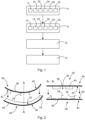
- Fig.1 shows a method 2 for producing a torsion box for a structure of an aircraft.
- the method can have the following steps according to the block diagram shown.
- a first component made of a fiber composite material is provided 4, which has a first flat base with a first inner side and a first outer side, wherein a plurality of first stiffening elements are arranged on the first inner side 6 and form a composite with the first base.
- a second component made of a fiber composite material is provided 8.
- the second component has a second flat base with a second inner side and a second outer side, wherein a plurality of second stiffening elements are arranged on the second inner side 10 and form a composite with the second base.
- the provision 4 or 8 can include the formation 16 or 18 of first or second plies on a mold, the covering 20 or 22, the impregnation 24 or 26 with a resin, the curing 28 or 30 and the removal 32 or 34.
- the formation 16 or 18 of the plies can include the arrangement 16a of a base ply to form the base and the arrangement of stiffening plies 16b to form the stiffening elements.
- the connection 14 could include the production of riveted connections.
- Fig.2 shows a first component 36, which has a first flat base 38.
- the first base 38 has a first outer side 40 and a first inner side 42.
- First stiffening elements 44 are arranged on the first inner side 42, which extend parallel to one another along the same direction and are designed as ribs, for example.
- the first base 38 and the first stiffening elements 44 are designed as a continuous layer and can be infiltrated and cured together with resin.
- a second component 46 has a second base 48 with a second outer side 50 and a second inner side 52. On this there are second stiffening elements 54, which are designed as spars. As can be seen in the sectional view, which is marked with A-A in the right-hand drawing plane, the first stiffening elements 44 have several interruptions 56 through which the second stiffening elements 54, which are arranged transversely to the first stiffening elements 44, can run.
- the first component 36 and the second component 46 are placed on top of one another and connected to one another.
- FIG. 3a Very schematically shows Fig. 3a a molding tool 58 on which a first base layer 60 is placed to form the first base 38. This is followed by first stiffening layers 62, which are arranged on the first base layer 60. A first closure device 64 is placed over the layers 60 and 62 and closes with the mold 58 flush. Gaps between the first stiffening layers 62 are also covered by the first closure device 64. In this position, the infiltration with resin and the subsequent curing can take place.
- the method shown relates in particular to a vacuum infusion method.
- Fig. 3b a slightly modified variant is shown in which the first base layer 60 and the first stiffening layers 62 are arranged on top of one another.
- a different first closure device 66 is selected, which does not run into the gaps between the first stiffening layers 62.
- first reinforcing elements 68 are arranged there, which supplement the gaps in the radial direction and are covered by the first closure device 66. After curing, they are removed again in a direction parallel to the first stiffening layers 62 or the resulting first stiffening elements. For this purpose, it is particularly advantageous if the stiffening layers 62 all run in the same direction. The first reinforcing elements 68 can then be pulled out in the same direction.
- This illustration relates in particular to an RTM process.
- Fig.4 now shows an aircraft 70 which has several structural components in the form of wings 72, horizontal stabilizers 74 and vertical stabilizers 76. At least one of these structural components 72, 74 and 76 can be equipped with a torsion box produced as shown above. As an example, a torsion box 78 is indicated by dashed lines at one end of one of the wings 72.
Landscapes
- Engineering & Computer Science (AREA)
- Mechanical Engineering (AREA)
- Aviation & Aerospace Engineering (AREA)
- Manufacturing & Machinery (AREA)
- Transportation (AREA)
- Moulding By Coating Moulds (AREA)
Description
- Die Erfindung betrifft ein Verfahren zum Herstellen eines Torsionskastens für eine Struktur eines Flugzeugs sowie einen Torsionskasten für eine Struktur eines Flugzeugs.
- Großformatige Bauteile aus einem Faserverbundwerkstoff können durch unterschiedliche Verfahren hergestellt werden. Neben Spritzpressverfahren sind auch Vakuuminfusionsverfahren verbreitet. Diese Verfahren basieren auf der Verwendung von Formwerkzeugen, die eine herzustellende Form des entsprechenden Bauteils vorgeben und mit einem Gelege aus einer oder mehreren Lagen eines Faserhalbzeugs versehen werden. Zum Tränken des Faserhalbzeugs mit Harz wird das hergestellte Gelege oftmals mit einer mit einer Vakuumfolie abgedeckt. Bei flächigen Bauteilen ist dies recht einfach, da die Vakuumfolie der flächigen Erstreckung des betreffenden Bauteils leicht folgen kann. Sind jedoch beispielsweise an einer Innenseite des betreffenden Bauteils längliche, parallel zueinander erstreckende Verstärkungsbauteile gewünscht, muss die Vakuumfolie auch den Verstärkungsbauteilen und den dazwischenliegenden Lücken bündig folgen. Ein Faltenwurf ist dabei zu verhindern, um die Formtreue und Integrität des Bauteils sicherzustellen.
- Insbesondere bei Verkehrsflugzeugen, welche zumindest teilweise großformatige, aus Faserverbundwerkstoffen hergestellte Bauteile aufweisen, sind teilweise deutlich komplexere Versteifungsbauteile vorgesehen. Bei sogenannten Torsionskästen, welche dazu ausgebildet sind, größere Biegemomente aufzunehmen, können Verstärkungsbauteile auch quer zueinander verlaufen und sich teilweise überschneiden. Aus diesem Grunde ist es verbreitet, zur Herstellung von Torsionskästen flächige Schalen herzustellen und separat gefertigte Verstärkungsbauteile auf die Schalen zu nieten oder auf andere Weise damit zu verbinden. Der hierzu notwendige Herstellaufwand ist beträchtlich und bei dem Herstellen der Nietverbindungen ist ein Faserverlauf entsprechend anzupassen oder zu dimensionieren.
- Die Schrift
US 4739954 A offenbart einen Flugzeugflügel mit einer Mehrzahl von Rippenpaaren wobei jedes Rippenpaar eine erste und eine zweite Rippe aufweist, die im Wesentlichen eben und so geformt sind, dass sie mit dem Querschnitt des Flügels zusammenpassen; und mit einem ersten Hauptspantloch, das durch diese erste Rippe hindurch führt, und ein zweites Hauptspantloch welches durch die zweite Rippe hindurch führt; wobei die erste Rippe fest an die ober Oberfläche des Flügels angebunden ist und die zweite Rippe an die untere Oberfläche des Flügels angebunden ist, wobei die genannte erste und zweite Rippe so überlappen, dass eine ebene Oberfläche der ersten Rippe im Wesentlichen parallel zu einer ebenen Oberfläche der zweiten Rippe angeordnet ist; sowie ein Hauptspant, der so bemessen ist, dass er sowohl in das erste Hauptspantloch der ersten Rippe und in das zweite Hauptspantloch der zweiten Rippe eingefügt ist, wenn die obere Oberfläche zu der unteren Oberfläche ausgerichtet wird, um einen Flugzeugflügel zu bilden und dadurch die obere und die untere Oberfläche miteinander zu verbinden. - Es ist eine Aufgabe der Erfindung, ein Verfahren zum Herstellen eines Torsionskastens für eine Struktur eines Flugzeugs vorzuschlagen, bei dem der Arbeitsaufwand reduziert werden kann, ohne dass eine abweichende Auslegung oder ein höheres Gewicht für den hergestellten Torsionskasten resultiert.
- Die Aufgabe wird gelöst durch ein Verfahren mit den Merkmalen des unabhängigen Anspruchs 1. Vorteilhafte Ausführungsformen und Weiterbildungen sind den Unteransprüchen und der nachfolgenden Beschreibung zu entnehmen.
- Es wird ein Verfahren zum Herstellen eines Torsionskastens für eine Struktur eines Flugzeugs vorgeschlagen, das Verfahren aufweisend die Schritte des Bereitstellens einer ersten Komponente aus einem Faserverbundwerkstoff, die erste Komponente aufweisend eine erste flächige Basis mit einer ersten Innenseite und einer ersten Außenseite, wobei mehrere erste Versteifungselemente an der ersten Innenseite angeordnet sind und einen Verbund mit der ersten Basis bilden, des Bereitstellens einer zweiten Komponente aus einem Faserverbundwerkstoff, die zweite Komponente aufweisend eine zweite flächige Basis mit einer zweiten Innenseite und einer zweiten Außenseite, wobei mehrere zweite Versteifungselemente an der zweiten Innenseite angeordnet sind und einen Verbund mit der zweiten Basis bilden, des Aufeinandersetzens der ersten Komponente und der zweiten Komponente derart, dass sich die ersten Versteifungselemente zumindest bereichsweise auf die zweite Innenseite legen und sich die zweiten Versteifungselemente zumindest bereichsweise auf die erste Innenseite legen, und des Verbindens der ersten Versteifungselemente mit der zweiten Basis und Verbinden der zweiten Versteifungselemente mit der ersten Basis.
- Ein solcher Torsionskasten könnte etwa ein Bauteil eines Flügels, eines Höhenleitwerks, eines Seitenleitwerks, einer Landeklappe oder eines anderen Strukturbauteils oder einer Struktur sein. Der Torsionskasten beschreibt ein hohles Strukturbauteil, welches dazu ausgebildet ist, ein Biegemoment um mindestens eine Achse aufzunehmen. Der Torsionskasten kann unterschiedliche Ausformungen aufweisen, die von eher würfelförmigen zu länglicheren quaderförmigen oder flächigeren Formen reichen. Die Wände des Torsionskastens müssen nicht flach sein, sondern können auch mehr oder weniger signifikante Krümmungen besitzen. Weiter nachfolgend ist der Torsionskasten durch zwei flächige, schalenartige Bauteile in Form der ersten Basis und der zweiten Basis gekennzeichnet, die in einem Abstand zueinander vorliegen und erste und zweite Versteifungselemente einschließen. Es ist besonders vorteilhaft, die erste Komponente und die zweite Komponente auf die oben angegebene Weise herzustellen.
- Die erste flächige Basis wird mit ersten Versteifungselementen versehen, die einen Verbund mit der ersten Basis ausbilden. Dies kann, wie vorangehend erläutert, das Anfertigen von Gelegen und eine anschließende Infiltrierung und Aushärtung umfassen. Dazu wird zum Durchführen des Infiltrierens und während des Aushärtens eine Verschlusseinrichtung auf den Gelege angeordnet. Die Verschlusseinrichtung kann etwa in Zwischenräume zwischen den ersten Versteifungselemente geraten. Alternativ dazu können die Zwischenräume auch mit Verstärkungselementen temporär belegt werden, so dass die Verschlusseinrichtung anschließend die Gelege und die Verstärkungselemente gemeinsam überdeckt.
- Dies ist bei Beschränkung auf die ersten Versteifungselemente oder die zweiten Versteifungselemente besonders vorteilhaft durchführbar, denn eine flexible Verschlusseinrichtung kann gleichmäßig angeordneten und vollständig durchgehenden Zwischenräumen ohne Faltenwurf folgen. Andererseits können die Verstärkungselemente nach dem Aushärten auch in einer Richtung aus der ersten Komponente oder der zweiten Komponente herausgeschoben werden.
- Daraus resultieren einfach und mit gewöhnlichen Werkzeugen herstellbare erste und zweite Komponenten, die einen Teil der im Stand der Technik erforderlichen Verbindungen einsparen. Die erste flächige Basis und die ersten Versteifungselemente sowie die zweite flächige Basis und die zweiten Versteifungselemente bilden jeweils ein zusammenhängendes, nicht gefügtes Bauteil mit einer Innenversteifung aus. Das Aufeinandersetzen erlaubt durch jeweils einseitiges Verbinden der Versteifungsbauteile das Herstellen des Torsionskastens. Der Aufwand für das Befestigen der einzelnen Komponenten aneinander wird folglich im Wesentlichen halbiert.
- Bei der Verwendung von Nietverbindungen ist ungefähr die Hälfte an entsprechenden Bohrungen notwendig, so dass eine Verbesserung des Kraftflusses und der für die Nietverbindungen notwendigen mechanischen Anpassungen im Vergleich zu ausschließlich gemieteten Komponenten zu erwarten ist.
- In einer vorteilhaften Ausführungsform weist das Bereitstellen der ersten Komponente bzw. der zweiten Komponente das Ausbilden von Gelegen auf einem Formwerkzeug, das Abdecken der Gelege mit einer Verschlusseinrichtung, das Tränken der Gelege mit einem Harz, das Aushärten und das Entfernen der Verschlusseinrichtung auf. Insbesondere könnte das Verfahren in Form eines Vakuum-Infusionsverfahrens oder als Harz-Spritzpressverfahren (Resin Transfer Molding, RTM) realisiert werden. Das Gelege wird auf dem Formwerkzeug mittels einer Verschlusseinrichtung, etwa einer Vakuumfolie, rundum abgedichtet, so dass es luftdicht und formsicher auf dem Formwerkzeug gekapselt ist. Der Begriff "Harz" kann im Sinne der Erfindung ein beliebiges Matrixmaterial aufweisen, welches dazu geeignet ist, mit einem Fasermaterial ein Faserverbundbauteil zu bilden. Das Matrixmaterial kann dabei auch bereits einen Härter enthalten (Mehrkomponentenharzsystem). Harz kann sich im engeren Sinne auf duroplastische Kunststoffe, etwa Epoxidharzsysteme, beziehen. Nicht ausgeschlossen sein sollen jedoch auch thermoplastische Kunststoffe.
- Das Ausbilden von Gelegen könnte das Anordnen eines Basisgeleges zum Ausbilden der Basis und von Versteifungsgelegen zum Ausbilden der Versteifungselemente aufweisen. Folglich wird ein einstückiges Verbundbauteil durch gemeinsames Aushärten von mit Harz getränkten Gelegen ermöglicht, was besonders vorteilhafte mechanische Eigenschaften im Übergangsbereich zwischen Versteifungsbauteilen und Basis besitzt sowie ein relativ geringes Gewicht aufweist.
- In einer vorteilhaften Ausführungsform werden die ersten Versteifungselemente und/oder die zweiten Versteifungselemente auf ihre zugehörige Basis geklebt oder geschweißt, um den Verbund mit der zugehörigen Basis zu bilden. Das Schweißen eignet sich besonders für eine Basis und Versteifungselemente, die auf einem Material mit einer thermoplastischen Matrix basieren. Das Kleben ist weitgehend für sämtliche Materialien denkbar, die auch Duromere umfassen.
- Besonders bevorzugt erstrecken sich die ersten Versteifungselemente bzw. die zweiten Versteifungselemente entlang derselben Raumrichtung. Sind mehrere Versteifungselemente auf der jeweiligen Basis angeordnet, sind diese parallel zueinander angeordnet. Die Zwischenräume zwischen den Versteifungselementen lassen sich gut mit einer flexiblen Verschlusseinrichtung formgenau und ohne Faltenwurf abdecken. Die Abstände könnten variabel ausgebildet sein, ebenso die einzelnen Bauhöhen oder Tiefenerstreckungen der Querschnittsprofile.
- Bevorzugt weist das Verbinden das Anfertigen von Nietverbindungen auf. Die erste Komponente und die zweite Komponente werden demgemäß an ihren Verbindungsstellen miteinander vernietet. Die Anzahl der Nietverbindungen beträgt jedoch lediglich ungefähr der Hälfte der Nietverbindungen der vorangehend geschilderten bekannten Verfahren zum Herstellen eines Torsionskastens.
- In einer vorteilhaften Ausführungsform werden die zweiten Versteifungselemente quer zu den ersten Versteifungselementen ausgerichtet. Die separate Fertigung der Versteifungselemente an der jeweiligen Basis erlauben das anschließende Verschachteln der Versteifungselemente für die robuste Konstruktion des Torsionskastens, ohne dass das Abdecken von Gelegen erschwert wird.
- Die ersten Versteifungselemente werden bereichsweise zumindest teilweise unterbrochen ausgeführt, um die zweiten Versteifungselemente durchzuführen. Die ersten und zweiten Versteifungselemente können damit ein Gitter innerhalb des Torsionskastens bilden.
- Bevorzugt sind die ersten Versteifungselemente als Versteifungsrippen ausgeführt. Die zweiten Versteifungselemente können weiter bevorzugt als Holme ausgeführt werden.
- Die Erfindung betrifft ferner einen Torsionskasten für eine Struktur eines Flugzeugs, aufweisend eine erste Komponente aus einem Faserverbundwerkstoff, die erste Komponente aufweisend eine erste flächige Basis mit einer ersten Innenseite und einer ersten Außenseite, wobei mehrere erste Versteifungselemente an der ersten Innenseite angeordnet sind und einen Verbund mit der ersten Basis bilden, und eine zweite Komponente aus einem Faserverbundwerkstoff, die zweite Komponente aufweisend eine zweite flächige Basis mit einer zweiten Innenseite und einer zweiten Außenseite, wobei mehrere zweite Versteifungselemente an der zweiten Innenseite angeordnet sind und einen Verbund mit der zweiten Basis bilden, wobei die erste Basis und die zweite Basis derart aufeinandergesetzt sind, dass die ersten Versteifungselemente zumindest bereichsweise auf der zweiten Innenseite liegen und die zweiten Versteifungselemente zumindest bereichsweise auf der ersten Innenseite liegen, und wobei die ersten Versteifungselemente mit der zweiten Basis und die zweiten Versteifungselemente mit der ersten Basis form-, kraft- oder stoffschlüssig miteinander verbunden sind.
- Besonders bevorzugt sind die ersten Versteifungselemente als Versteifungsrippen ausgeführt, wobei die zweiten Versteifungselemente als Holme ausgeführt sind und wobei die ersten und die zweiten Versteifungselemente quer zueinander angeordnet sind.
- Ferner betrifft die Erfindung ein Flugzeug, aufweisend mindestens eine Komponente, die einen Torsionskasten nach der vorhergehenden Beschreibung aufweist.
- Weitere Merkmale, Vorteile und Anwendungsmöglichkeiten der vorliegenden Erfindung ergeben sich aus der nachfolgenden Beschreibung der Ausführungsbeispiele und den Figuren. Dabei bilden alle beschriebenen und/oder bildlich dargestellten Merkmale für sich und in beliebiger Kombination den Gegenstand der Erfindung auch unabhängig von ihrer Zusammensetzung in den einzelnen Ansprüchen oder deren Rückbezügen. In den Figuren stehen weiterhin gleiche Bezugszeichen für gleiche oder ähnliche Objekte.
-
Fig. 1 zeigt ein schematisches, blockbasiertes Diagramm eines Verfahrens zum Herstellen eines Torsionskastens für eine Struktur eines Flugzeugs. -
Fig. 2 zeigt die erste und die zweite Komponente in zwei unterschiedlichen Ansichten. -
Fig. 3a und 3b zeigen das Herstellen einer ersten Komponente auf einem Formwerkzeug. -
Fig. 4 zeigt ein Flugzeug, das einen Torsionskasten aufweist. -
Fig. 1 zeigt ein Verfahren 2 zum Herstellen eines Torsionskastens für eine Struktur eines Flugzeugs. Das Verfahren kann gemäß der gezeigten Blockdarstellung die folgenden Schritte aufweisen. Zunächst wird eine erste Komponente aus einem Faserverbundwerkstoff bereitgestellt 4, die eine erste flächige Basis mit einer ersten Innenseite und einer ersten Außenseite aufweist, wobei mehrere erste Versteifungselemente auf der ersten Innenseite angeordnet werden 6 und einen Verbund mit der ersten Basis bilden. Anschließend wird eine zweite Komponente aus einem Faserverbundwerkstoff bereitgestellt 8. Die zweite Komponente weist eine zweite flächige Basis mit einer zweiten Innenseite und einer zweiten Außenseite auf, wobei mehrere zweite Versteifungselemente an der zweiten Innenseite angeordnet werden 10 und einen Verbund mit der zweiten Basis bilden. Anschließend werden die erste Komponente und die zweite Komponente derart aufeinander gesetzt 12, dass sich die ersten Versteifungselemente zumindest bereichsweise auf die zweite Innenseite legen und sich die zweiten Versteifungselemente zumindest bereichsweise auf die erste Innenseite legen. Dann werden die ersten Versteifungselemente mit der zweiten Basis und die zweiten Versteifungselemente mit der ersten Basis verbunden 14. Das Bereitstellen 4 bzw. 8 kann das Ausbilden 16 bzw. 18 von ersten bzw. zweiten Gelegen auf einem Formwerkzeug aufweisen, das Abdecken 20 bzw. 22, das Tränken 24 bzw. 26 mit einem Harz, das Aushärten 28 bzw. 30 und das Entfernen 32 bzw. 34. Das Ausbilden 16 bzw. 18 der Gelege kann das Anordnen 16a eines Basisgeleges zum Ausbilden der Basis und das Anordnen von Versteifungsgelegen 16b zum Ausbilden der Versteifungselemente aufweisen. Das Verbinden 14 könnte das Anfertigen von Nietverbindungen aufweisen. -
Fig. 2 zeigt eine erste Komponente 36, die eine erste flächige Basis 38 aufweist. Die erste Basis 38 besitzt eine erste Außenseite 40 und eine erste Innenseite 42. An der ersten Innenseite 42 sind erste Versteifungselemente 44 angeordnet, die sich parallel zueinander entlang derselben Richtung erstrecken und beispielhaft als Rippen ausgeführt sind. Exemplarisch sind die erste Basis 38 und die ersten Versteifungselemente 44 als ein zusammenhängendes Gelege ausgebildet und können gemeinsam mit Harz infiltriert und ausgehärtet werden - Eine zweite Komponente 46 weist eine zweite Basis 48 mit einer zweiten Außenseite 50 und einer zweiten Innenseite 52 auf. Auf dieser befinden sich zweite Versteifungselemente 54, die als Holme ausgeführt sind. Wie in der Schnittdarstellung ersichtlich ist, welche in der rechten Zeichnungsebene mit A-A gekennzeichnet ist, weisen die ersten Versteifungselemente 44 mehrere Unterbrechungen 56 auf, durch die die zweiten Versteifungselemente 54, welche quer zu den ersten Versteifungselemente 44 angeordnet sind, verlaufen können. Die erste Komponente 36 und die zweite Komponente 46 werden aufeinander gesetzt und miteinander verbunden.
- Sehr schematisch zeigt
Fig. 3a ein Formwerkzeug 58, auf dem ein erstes Basisgelege 60 zum Ausbilden der ersten Basis 38 aufgelegt ist. Hieran schließen sich erste Versteifungsgelege 62 an, die auf dem ersten Basisgelege 60 angeordnet sind. Eine erste Verschlusseinrichtung 64 ist über die Gelege 60 und 62 gelegt und schließt mit dem Formwerkzeug 58 bündig ab. Zwischenräume zwischen den ersten Versteifungsgelegen 62 werden ebenso von der ersten Verschlusseinrichtung 64 abgedeckt. In dieser Position kann das Infiltrieren mit Harz erfolgen sowie das anschließende Aushärten. Das dargestellte Verfahren betrifft insbesondere ein Vakuum-Infusionsverfahren. - In
Fig. 3b wird eine etwas modifizierte Variante gezeigt, bei der das erste Basisgelege 60 und die ersten Versteifungsgelege 62 aufeinander angeordnet werden. Hier ist eine andere erste Verschlusseinrichtung 66 gewählt, welche nicht in Zwischenräume zwischen den ersten Versteifungsgelegen 62 hinein verläuft. Dort sind stattdessen erste Verstärkungselemente 68 angeordnet, die die Zwischenräume in radialer Richtung ergänzen und durch die erste Verschlusseinrichtung 66 überdeckt werden. Nach dem Aushärten werden sie in einer Richtung parallel zu den ersten Versteifungsgelegen 62 bzw. den resultierenden ersten Versteifungselementen wieder entfernt. Hierzu ist es besonders günstig, dass die Versteifungsgelege 62 alle in derselben Richtung verlaufen. Die ersten Verstärkungselemente 68 können dann in derselben Richtung herausgezogen werden. Diese Darstellung betrifft insbesondere ein RTM-Verfahren. - Für die Herstellung der zweiten Komponente 46 werden analog zu
Fig. 3a oder 3b geformte Einrichtungen verwendet. -
Fig. 4 zeigt nun ein Flugzeug 70, welches mehrere Strukturkomponenten in Form von Flügeln 72, Höhenleitwerken 74 und Seitenleitwerk 76 aufweist. Mindestens eine dieser Strukturkomponenten 72, 74 und 76 kann mit einem vorangehend dargestellt hergestellten Torsionskasten ausgestattet werden. Beispielhaft ist ein Torsionskasten 78 gestrichelt an einem Ende einer der Flügel 72 angedeutet. - Ergänzend sei darauf hingewiesen, dass "aufweisend" keine anderen Elemente oder Schritte ausschließt, und "ein" oder "eine" keine Vielzahl ausschließt. Ferner sei darauf hingewiesen, dass Merkmale, die mit Verweis auf eines der obigen Ausführungsbeispiele beschrieben worden sind, auch in Kombination mit anderen Merkmalen anderer oben beschriebener Ausführungsbeispiele verwendet werden können. Bezugszeichen in den Ansprüchen sind nicht als Einschränkung anzusehen.
-
- 2
- Verfahren
- 4
- Bereitstellen erster Komponente
- 6
- Anordnen erster Versteifungselemente
- 8
- Bereitstellen zweiter Komponente
- 10
- Anordnen zweiter Versteifungselemente
- 12
- Aufeinandersetzen
- 14
- Verbinden
- 16
- Ausbilden erster Gelege
- 18
- Ausbilden zweiter Gelege
- 20
- Abdecken erster Gelege
- 22
- Abdecken zweiter Gelege
- 24
- Tränken erster Gelege
- 26
- Tränken zweiter Gelege
- 28
- Aushärten erster Gelege
- 30
- Aushärten zweiter Gelege
- 32
- Entfernen Verschlusseinrichtung
- 34
- Entfernen Verschlusseinrichtung
- 36
- erste Komponente
- 38
- erste Basis
- 40
- erste Außenseite
- 42
- erste Innenseite
- 44
- erste Versteifungselemente
- 46
- zweite Komponente
- 48
- zweite Basis
- 50
- zweite Außenseite
- 52
- zweite Innenseite
- 54
- zweite Versteifungselemente
- 56
- Unterbrechungen
- 58
- Formwerkzeug
- 60
- erstes Basisgelege
- 62
- erste Versteifungsgelege
- 64
- erste Verschlusseinrichtung
- 66
- erste Verschlusseinrichtung
- 68
- erste Verstärkungselemente
- 70
- Flugzeug
- 72
- Flügel
- 74
- Höhenleitwerk
- 76
- Seitenleitwerk
- 78
- Torsionskasten
Claims (13)
- Verfahren (2) zum Herstellen eines Torsionskastens (78) für eine Struktur eines Flugzeugs (70), aufweisend die Schritte:- Bereitstellen (4) einer ersten Komponente (36) aus einem Faserverbundwerkstoff, die erste Komponente (36) aufweisend eine erste flächige Basis (38) mit einer ersten Innenseite (42) und einer ersten Außenseite (40), wobei mehrere erste Versteifungselemente (44) an der ersten Innenseite (42) angeordnet werden (6) und einen Verbund mit der ersten Basis (38) bilden,- Bereitstellen (8) einer zweiten Komponente (46) aus einem Faserverbundwerkstoff, die zweite Komponente (46) aufweisend eine zweite flächige Basis (48) mit einer zweiten Innenseite (52) und einer zweiten Außenseite (50), wobei mehrere zweite Versteifungselemente (54) an der zweiten Innenseite (52) angeordnet werden und einen Verbund mit der zweiten Basis (48) bilden,- Aufeinandersetzen (12) der ersten Komponente (36) und der zweiten Komponente (46) derart, dass sich die ersten Versteifungselemente (44) zumindest bereichsweise auf die zweite Innenseite (52) legen und sich die zweiten Versteifungselemente (54) zumindest bereichsweise auf die erste Innenseite (42) legen,
gekennzeichnet durch- Verbinden (14) der ersten Versteifungselemente (44) mit der zweiten Basis (48) und Verbinden (14) der zweiten Versteifungselemente (54) mit der ersten Basis (38). - Verfahren (2) nach Anspruch 1,
wobei das Bereitstellen (4, 8) der ersten Komponente (36) bzw. der zweiten Komponente (46) das Ausbilden (16, 18) von Gelegen (60, 62) auf einem Formwerkzeug (58), das Abdecken (20, 22) der Gelege (60, 62) mit einer Verschlusseinrichtung (64, 66), das Tränken (24, 26) der Gelege (60, 62) mit einem Harz, das Aushärten (28, 30) und das Entfernen (32, 34) der Verschlusseinrichtung (64, 66) aufweist. - Verfahren (2) nach Anspruch 2,
wobei das Ausbilden (16, 18) von Gelegen (60, 62) das Anordnen eines Basisgeleges (60) zum Ausbilden der Basis (38, 48) und von Versteifungsgelegen (62) zum Ausbilden der Versteifungselemente (44, 54) aufweist. - Verfahren (2) nach Anspruch 1 oder 2,
wobei die ersten Versteifungselemente (44) und/oder die zweiten Versteifungselemente (54) auf ihre zugehörige Basis (38, 48) geklebt oder geschweißt werden, um den Verbund mit der zugehörigen Basis (38, 48) zu bilden. - Verfahren (2) nach einem der vorhergehenden Ansprüche,
wobei sich die ersten Versteifungselemente (44) bzw. die zweiten Versteifungselemente (54) entlang derselben Raumrichtung erstrecken. - Verfahren (2) nach einem der vorhergehenden Ansprüche, wobei das Verbinden (14) das Anfertigen von Nietverbindungen aufweist.
- Verfahren (2) nach einem der vorhergehenden Ansprüche,
wobei die zweiten Versteifungselemente (54) quer zu den ersten Versteifungselementen (44) ausgerichtet werden. - Verfahren (2) nach Anspruch 7,
wobei die ersten Versteifungselemente (44) bereichsweise zumindest teilweise unterbrochen ausgeführt werden, um die zweiten Versteifungselemente (54) durchzuführen. - Verfahren (2) nach einem der vorhergehenden Ansprüche,
wobei die ersten Versteifungselemente (44) als Versteifungsrippen ausgeführt werden. - Verfahren (2) nach einem der vorhergehenden Ansprüche,
wobei die zweiten Versteifungselemente (54) als Holme ausgeführt werden. - Torsionskasten (78) für eine Struktur eines Flugzeugs, aufweisend:- eine erste Komponente (36) aus einem Faserverbundwerkstoff, die erste Komponente (36) aufweisend eine erste flächige Basis (38) mit einer ersten Innenseite (42) und einer ersten Außenseite (40), wobei mehrere erste Versteifungselemente (44) an der ersten Innenseite (42) angeordnet sind und einen Verbund mit der ersten Basis (38) bilden, und- eine zweite Komponente (46) aus einem Faserverbundwerkstoff, die zweite Komponente (46) aufweisend eine zweite flächige Basis (48) mit einer zweiten Innenseite (52) und einer zweiten Außenseite (50), wobei mehrere zweite Versteifungselemente (54) an der zweiten Innenseite (50) angeordnet sind und einen Verbund mit der zweiten Basis (48) bilden,wobei die erste Basis (38) und die zweite Basis (48) derart aufeinandergesetzt sind, dass die ersten Versteifungselemente (44) zumindest bereichsweise auf der zweiten Innenseite (52) liegen und die zweiten Versteifungselemente (54) zumindest bereichsweise auf der ersten Innenseite (42) liegen, undwobei die ersten Versteifungselemente (44) mit der zweiten Basis (48) und die zweiten Versteifungselemente (54) mit der ersten Basis (38) form-, kraft- oder stoffschlüssig miteinander verbunden sind.
- Torsionskasten (78) nach Anspruch 11,wobei die ersten Versteifungselemente (44) als Versteifungsrippen ausgeführt sind,wobei die zweiten Versteifungselemente (54) als Holme ausgeführt sind undwobei die ersten und die zweiten Versteifungselemente (44, 54) quer zueinander angeordnet sind.
- Flugzeug (70), aufweisend mindestens eine Strukturkomponente (72, 74, 76), in die mindestens ein Torsionskasten (78) nach Anspruch 11 oder 12 integriert ist.
Applications Claiming Priority (2)
| Application Number | Priority Date | Filing Date | Title |
|---|---|---|---|
| DE102019123012.8A DE102019123012A1 (de) | 2019-08-28 | 2019-08-28 | Verfahren zum Herstellen eines Torsionskasten für eine Struktur eines Flugzeugs sowie ein Torsionskasten für eine Struktur eines Flugzeugs |
| PCT/IB2020/000903 WO2021038302A1 (de) | 2019-08-28 | 2020-08-31 | Verfahren zum herstellen eines torsionskasten für eine struktur eines flugzeugs sowie ein torsionskasten für eine struktur eines flugzeugs |
Publications (2)
| Publication Number | Publication Date |
|---|---|
| EP4021800A1 EP4021800A1 (de) | 2022-07-06 |
| EP4021800B1 true EP4021800B1 (de) | 2024-06-05 |
Family
ID=72521569
Family Applications (1)
| Application Number | Title | Priority Date | Filing Date |
|---|---|---|---|
| EP20820269.7A Active EP4021800B1 (de) | 2019-08-28 | 2020-08-31 | Verfahren zum herstellen eines torsionskasten für eine struktur eines flugzeugs sowie ein torsionskasten für eine struktur eines flugzeugs |
Country Status (5)
| Country | Link |
|---|---|
| US (1) | US12459221B2 (de) |
| EP (1) | EP4021800B1 (de) |
| CN (1) | CN114466789A (de) |
| DE (1) | DE102019123012A1 (de) |
| WO (1) | WO2021038302A1 (de) |
Family Cites Families (21)
| Publication number | Priority date | Publication date | Assignee | Title |
|---|---|---|---|---|
| US1603051A (en) * | 1923-01-31 | 1926-10-12 | Theodore P Hall | Airplane |
| US2233969A (en) * | 1938-12-30 | 1941-03-04 | Bell Aircraft Corp | Pressed wing rib |
| US4310132A (en) * | 1978-02-16 | 1982-01-12 | Nasa | Fuselage structure using advanced technology fiber reinforced composites |
| US4739954A (en) * | 1986-12-29 | 1988-04-26 | Hamilton Terry W | Over-lap rib joint |
| DE4315600C2 (de) * | 1993-05-11 | 1996-07-25 | Daimler Benz Aerospace Airbus | Tragstruktur für eine aerodynamische Fläche |
| US6638466B1 (en) * | 2000-12-28 | 2003-10-28 | Raytheon Aircraft Company | Methods of manufacturing separable structures |
| JP4574086B2 (ja) * | 2001-09-03 | 2010-11-04 | 富士重工業株式会社 | 複合材翼の製造方法および複合材翼 |
| JP2004025946A (ja) * | 2002-06-24 | 2004-01-29 | Honda Motor Co Ltd | 航空機の翼構造 |
| US7182293B2 (en) * | 2004-04-27 | 2007-02-27 | The Boeing Company | Airfoil box and associated method |
| JP4657189B2 (ja) * | 2006-11-02 | 2011-03-23 | 本田技研工業株式会社 | 飛行機の翼構造 |
| JP4990177B2 (ja) * | 2008-02-14 | 2012-08-01 | 本田技研工業株式会社 | 飛行機の翼構造 |
| EP2909008B1 (de) * | 2012-10-22 | 2018-04-11 | Saab Ab | Integrierte befestigung aus einer faserverstärkten kunststoffrippe an eine faserverstärkte kunststoffhaut für flugzeugflügel |
| ES2656854T3 (es) * | 2012-11-28 | 2018-02-28 | Airbus Operations S.L. | Una estructura principal de soporte de una superficie sustentadora de una aeronave |
| EP2989002B1 (de) * | 2013-04-25 | 2019-03-06 | Saab Ab | Verfahren und produktionslinie zur herstellung einer torsionskastenartigen hautverbundstruktur |
| ES2788529T3 (es) * | 2013-12-31 | 2020-10-21 | Airbus Operations Sl | Método de fabricación de un cajón infundido altamente integrado hecho de material compuesto |
| GB2533582A (en) * | 2014-12-22 | 2016-06-29 | Airbus Operations Ltd | Aircraft wing box, aircraft wing, aircraft and supporting member for use therein |
| GB201522327D0 (en) * | 2015-12-17 | 2016-02-03 | Airbus Operations Ltd | Wing structure |
| GB2550403A (en) * | 2016-05-19 | 2017-11-22 | Airbus Operations Ltd | Aerofoil body with integral curved spar-cover |
| US20180086429A1 (en) * | 2016-09-28 | 2018-03-29 | The Boeing Company | Airfoil-Shaped Body Having Composite Base Skin with Integral Hat-Shaped Spar |
| EP3330174B1 (de) * | 2016-12-02 | 2019-10-30 | Airbus Operations, S.L. | Flugzeugstabilisatorvorderkantenintegration mit einem torsionskasten und rumpf |
| GB2584423A (en) * | 2019-05-28 | 2020-12-09 | Airbus Operations Ltd | Rib mounting assembly |
-
2019
- 2019-08-28 DE DE102019123012.8A patent/DE102019123012A1/de not_active Withdrawn
-
2020
- 2020-08-31 WO PCT/IB2020/000903 patent/WO2021038302A1/de not_active Ceased
- 2020-08-31 EP EP20820269.7A patent/EP4021800B1/de active Active
- 2020-08-31 CN CN202080039425.7A patent/CN114466789A/zh active Pending
-
2021
- 2021-11-26 US US17/535,885 patent/US12459221B2/en active Active
Also Published As
| Publication number | Publication date |
|---|---|
| US12459221B2 (en) | 2025-11-04 |
| CN114466789A (zh) | 2022-05-10 |
| EP4021800A1 (de) | 2022-07-06 |
| DE102019123012A1 (de) | 2021-03-04 |
| WO2021038302A1 (de) | 2021-03-04 |
| US20220080686A1 (en) | 2022-03-17 |
Similar Documents
| Publication | Publication Date | Title |
|---|---|---|
| EP2046564B1 (de) | Verfahren zur Herstellung von mehreren Faserverbundbauteilen | |
| EP3444107B1 (de) | Verfahren zur herstellung eines sandwichbauteils, kern für ein sandwichbauteil sowie sandwichbauteil | |
| DE102007003275B4 (de) | Schalenelement als Teil eines Flugzeugrumpfes | |
| DE3113791C2 (de) | ||
| DE69911507T2 (de) | Flügelstruktur aus Faserverbundstoff | |
| DE3806594C2 (de) | Abnehmbarer oder schwenkbarer Bauteil zum Verkleiden von Öffnungen im Rumpf eines Flugzeuges sowie Verfahren zur Herstellung des Bauteiles und Vorrichtung zur Durchführung des Verfahrens | |
| DE102014106743B4 (de) | Strömungskörper mit einem darin integrierten Lasteinleitungselement, Verfahren zum Herstellen eines Strömungskörpers und Flugzeug mit einem solchen Strömungskörper | |
| DE102012000564B4 (de) | Urformwerkzeug und Verfahren für die Fertigung eines aus faserverstärktem Kunststoff bestehenden aerodynamisch geformten Luftfahrzeugbauteils | |
| DE60200504T2 (de) | Verfahren zum herstellen eines verbundmaterialtrageflügels und verbundmaterial-trageflügel | |
| EP2419325B1 (de) | Spant und verfahren zur herstellung eines solchen spants | |
| DE102006031335A1 (de) | Verfahren zur Herstellung eines Faserverbundbauteils für die Luft- und Raumfahrt | |
| WO2012013770A2 (de) | Stabwickelstruktur in compositebauweise | |
| DE102021118286B4 (de) | Unterbodenschutzelement aus duroplastischem Material, Herstellungsverfahren und Kraftfahrzeug mit einem Unterbodenschutzelement | |
| DE102017126052A1 (de) | Versteifungsanordnung für eine Öffnung in einer Flugzeugstruktur | |
| DE102012109231A1 (de) | integrale Verstärkungselemente | |
| EP3286078B1 (de) | Steuerflächenelement | |
| DE1923888C3 (de) | Verfahren zur Herstellung einer Verdichterschaufel aus faserverstärktem Material | |
| DE102017128496B4 (de) | Verfahren zum Herstellen eines Strukturabschnitts eines Fahrzeugs | |
| EP0690228A1 (de) | Montage- und Biegeträger eines Flügels | |
| DE102014221356B4 (de) | Baugruppe mit Einzelkomponenten aus einem faserverstärkten Verbundmaterial | |
| DE102016124966A1 (de) | Bauteilstruktur und Verfahren zur Herstellung derselben | |
| EP3677418B1 (de) | Rumpfbauteil für ein luftfahrzeug, verfahren zur herstellung eines rumpfbauteils sowie luftfahrzeug | |
| DE102019111836A1 (de) | Profilbauteil zur Verstärkung von Bauteilstrukturen, Bauteilstruktur sowie Herstellungsverfahren hierzu | |
| WO2021038302A1 (de) | Verfahren zum herstellen eines torsionskasten für eine struktur eines flugzeugs sowie ein torsionskasten für eine struktur eines flugzeugs | |
| EP0261375B1 (de) | Verfahren zum Herstellen eines Faserverbund-Hohlträgers |
Legal Events
| Date | Code | Title | Description |
|---|---|---|---|
| STAA | Information on the status of an ep patent application or granted ep patent |
Free format text: STATUS: UNKNOWN |
|
| STAA | Information on the status of an ep patent application or granted ep patent |
Free format text: STATUS: THE INTERNATIONAL PUBLICATION HAS BEEN MADE |
|
| PUAI | Public reference made under article 153(3) epc to a published international application that has entered the european phase |
Free format text: ORIGINAL CODE: 0009012 |
|
| STAA | Information on the status of an ep patent application or granted ep patent |
Free format text: STATUS: REQUEST FOR EXAMINATION WAS MADE |
|
| 17P | Request for examination filed |
Effective date: 20220328 |
|
| AK | Designated contracting states |
Kind code of ref document: A1 Designated state(s): AL AT BE BG CH CY CZ DE DK EE ES FI FR GB GR HR HU IE IS IT LI LT LU LV MC MK MT NL NO PL PT RO RS SE SI SK SM TR |
|
| RAP3 | Party data changed (applicant data changed or rights of an application transferred) |
Owner name: AIRBUS OPERATIONS GMBH |
|
| DAV | Request for validation of the european patent (deleted) | ||
| DAX | Request for extension of the european patent (deleted) | ||
| GRAP | Despatch of communication of intention to grant a patent |
Free format text: ORIGINAL CODE: EPIDOSNIGR1 |
|
| STAA | Information on the status of an ep patent application or granted ep patent |
Free format text: STATUS: GRANT OF PATENT IS INTENDED |
|
| INTG | Intention to grant announced |
Effective date: 20240108 |
|
| GRAS | Grant fee paid |
Free format text: ORIGINAL CODE: EPIDOSNIGR3 |
|
| GRAA | (expected) grant |
Free format text: ORIGINAL CODE: 0009210 |
|
| STAA | Information on the status of an ep patent application or granted ep patent |
Free format text: STATUS: THE PATENT HAS BEEN GRANTED |
|
| AK | Designated contracting states |
Kind code of ref document: B1 Designated state(s): AL AT BE BG CH CY CZ DE DK EE ES FI FR GB GR HR HU IE IS IT LI LT LU LV MC MK MT NL NO PL PT RO RS SE SI SK SM TR |
|
| REG | Reference to a national code |
Ref country code: CH Ref legal event code: EP |
|
| REG | Reference to a national code |
Ref country code: DE Ref legal event code: R096 Ref document number: 502020008236 Country of ref document: DE |
|
| REG | Reference to a national code |
Ref country code: IE Ref legal event code: FG4D Free format text: LANGUAGE OF EP DOCUMENT: GERMAN |
|
| REG | Reference to a national code |
Ref country code: LT Ref legal event code: MG9D |
|
| PG25 | Lapsed in a contracting state [announced via postgrant information from national office to epo] |
Ref country code: BG Free format text: LAPSE BECAUSE OF FAILURE TO SUBMIT A TRANSLATION OF THE DESCRIPTION OR TO PAY THE FEE WITHIN THE PRESCRIBED TIME-LIMIT Effective date: 20240605 |
|
| REG | Reference to a national code |
Ref country code: NL Ref legal event code: MP Effective date: 20240605 |
|
| PG25 | Lapsed in a contracting state [announced via postgrant information from national office to epo] |
Ref country code: HR Free format text: LAPSE BECAUSE OF FAILURE TO SUBMIT A TRANSLATION OF THE DESCRIPTION OR TO PAY THE FEE WITHIN THE PRESCRIBED TIME-LIMIT Effective date: 20240605 Ref country code: FI Free format text: LAPSE BECAUSE OF FAILURE TO SUBMIT A TRANSLATION OF THE DESCRIPTION OR TO PAY THE FEE WITHIN THE PRESCRIBED TIME-LIMIT Effective date: 20240605 |
|
| PG25 | Lapsed in a contracting state [announced via postgrant information from national office to epo] |
Ref country code: GR Free format text: LAPSE BECAUSE OF FAILURE TO SUBMIT A TRANSLATION OF THE DESCRIPTION OR TO PAY THE FEE WITHIN THE PRESCRIBED TIME-LIMIT Effective date: 20240906 |
|
| PG25 | Lapsed in a contracting state [announced via postgrant information from national office to epo] |
Ref country code: ES Free format text: LAPSE BECAUSE OF FAILURE TO SUBMIT A TRANSLATION OF THE DESCRIPTION OR TO PAY THE FEE WITHIN THE PRESCRIBED TIME-LIMIT Effective date: 20240605 |
|
| PG25 | Lapsed in a contracting state [announced via postgrant information from national office to epo] |
Ref country code: LV Free format text: LAPSE BECAUSE OF FAILURE TO SUBMIT A TRANSLATION OF THE DESCRIPTION OR TO PAY THE FEE WITHIN THE PRESCRIBED TIME-LIMIT Effective date: 20240605 |
|
| PG25 | Lapsed in a contracting state [announced via postgrant information from national office to epo] |
Ref country code: NO Free format text: LAPSE BECAUSE OF FAILURE TO SUBMIT A TRANSLATION OF THE DESCRIPTION OR TO PAY THE FEE WITHIN THE PRESCRIBED TIME-LIMIT Effective date: 20240905 Ref country code: LV Free format text: LAPSE BECAUSE OF FAILURE TO SUBMIT A TRANSLATION OF THE DESCRIPTION OR TO PAY THE FEE WITHIN THE PRESCRIBED TIME-LIMIT Effective date: 20240605 Ref country code: HR Free format text: LAPSE BECAUSE OF FAILURE TO SUBMIT A TRANSLATION OF THE DESCRIPTION OR TO PAY THE FEE WITHIN THE PRESCRIBED TIME-LIMIT Effective date: 20240605 Ref country code: GR Free format text: LAPSE BECAUSE OF FAILURE TO SUBMIT A TRANSLATION OF THE DESCRIPTION OR TO PAY THE FEE WITHIN THE PRESCRIBED TIME-LIMIT Effective date: 20240906 Ref country code: FI Free format text: LAPSE BECAUSE OF FAILURE TO SUBMIT A TRANSLATION OF THE DESCRIPTION OR TO PAY THE FEE WITHIN THE PRESCRIBED TIME-LIMIT Effective date: 20240605 Ref country code: ES Free format text: LAPSE BECAUSE OF FAILURE TO SUBMIT A TRANSLATION OF THE DESCRIPTION OR TO PAY THE FEE WITHIN THE PRESCRIBED TIME-LIMIT Effective date: 20240605 Ref country code: BG Free format text: LAPSE BECAUSE OF FAILURE TO SUBMIT A TRANSLATION OF THE DESCRIPTION OR TO PAY THE FEE WITHIN THE PRESCRIBED TIME-LIMIT Effective date: 20240605 Ref country code: RS Free format text: LAPSE BECAUSE OF FAILURE TO SUBMIT A TRANSLATION OF THE DESCRIPTION OR TO PAY THE FEE WITHIN THE PRESCRIBED TIME-LIMIT Effective date: 20240905 |
|
| PG25 | Lapsed in a contracting state [announced via postgrant information from national office to epo] |
Ref country code: NL Free format text: LAPSE BECAUSE OF FAILURE TO SUBMIT A TRANSLATION OF THE DESCRIPTION OR TO PAY THE FEE WITHIN THE PRESCRIBED TIME-LIMIT Effective date: 20240605 |
|
| PG25 | Lapsed in a contracting state [announced via postgrant information from national office to epo] |
Ref country code: NL Free format text: LAPSE BECAUSE OF FAILURE TO SUBMIT A TRANSLATION OF THE DESCRIPTION OR TO PAY THE FEE WITHIN THE PRESCRIBED TIME-LIMIT Effective date: 20240605 |
|
| PG25 | Lapsed in a contracting state [announced via postgrant information from national office to epo] |
Ref country code: PT Free format text: LAPSE BECAUSE OF FAILURE TO SUBMIT A TRANSLATION OF THE DESCRIPTION OR TO PAY THE FEE WITHIN THE PRESCRIBED TIME-LIMIT Effective date: 20241007 |
|
| PG25 | Lapsed in a contracting state [announced via postgrant information from national office to epo] |
Ref country code: PT Free format text: LAPSE BECAUSE OF FAILURE TO SUBMIT A TRANSLATION OF THE DESCRIPTION OR TO PAY THE FEE WITHIN THE PRESCRIBED TIME-LIMIT Effective date: 20241007 |
|
| PG25 | Lapsed in a contracting state [announced via postgrant information from national office to epo] |
Ref country code: PL Free format text: LAPSE BECAUSE OF FAILURE TO SUBMIT A TRANSLATION OF THE DESCRIPTION OR TO PAY THE FEE WITHIN THE PRESCRIBED TIME-LIMIT Effective date: 20240605 |
|
| PG25 | Lapsed in a contracting state [announced via postgrant information from national office to epo] |
Ref country code: EE Free format text: LAPSE BECAUSE OF FAILURE TO SUBMIT A TRANSLATION OF THE DESCRIPTION OR TO PAY THE FEE WITHIN THE PRESCRIBED TIME-LIMIT Effective date: 20240605 |
|
| PG25 | Lapsed in a contracting state [announced via postgrant information from national office to epo] |
Ref country code: IS Free format text: LAPSE BECAUSE OF FAILURE TO SUBMIT A TRANSLATION OF THE DESCRIPTION OR TO PAY THE FEE WITHIN THE PRESCRIBED TIME-LIMIT Effective date: 20241005 |
|
| PG25 | Lapsed in a contracting state [announced via postgrant information from national office to epo] |
Ref country code: CZ Free format text: LAPSE BECAUSE OF FAILURE TO SUBMIT A TRANSLATION OF THE DESCRIPTION OR TO PAY THE FEE WITHIN THE PRESCRIBED TIME-LIMIT Effective date: 20240605 |
|
| PG25 | Lapsed in a contracting state [announced via postgrant information from national office to epo] |
Ref country code: RO Free format text: LAPSE BECAUSE OF FAILURE TO SUBMIT A TRANSLATION OF THE DESCRIPTION OR TO PAY THE FEE WITHIN THE PRESCRIBED TIME-LIMIT Effective date: 20240605 Ref country code: SK Free format text: LAPSE BECAUSE OF FAILURE TO SUBMIT A TRANSLATION OF THE DESCRIPTION OR TO PAY THE FEE WITHIN THE PRESCRIBED TIME-LIMIT Effective date: 20240605 |
|
| PG25 | Lapsed in a contracting state [announced via postgrant information from national office to epo] |
Ref country code: SM Free format text: LAPSE BECAUSE OF FAILURE TO SUBMIT A TRANSLATION OF THE DESCRIPTION OR TO PAY THE FEE WITHIN THE PRESCRIBED TIME-LIMIT Effective date: 20240605 |
|
| PG25 | Lapsed in a contracting state [announced via postgrant information from national office to epo] |
Ref country code: SM Free format text: LAPSE BECAUSE OF FAILURE TO SUBMIT A TRANSLATION OF THE DESCRIPTION OR TO PAY THE FEE WITHIN THE PRESCRIBED TIME-LIMIT Effective date: 20240605 Ref country code: SK Free format text: LAPSE BECAUSE OF FAILURE TO SUBMIT A TRANSLATION OF THE DESCRIPTION OR TO PAY THE FEE WITHIN THE PRESCRIBED TIME-LIMIT Effective date: 20240605 Ref country code: RO Free format text: LAPSE BECAUSE OF FAILURE TO SUBMIT A TRANSLATION OF THE DESCRIPTION OR TO PAY THE FEE WITHIN THE PRESCRIBED TIME-LIMIT Effective date: 20240605 Ref country code: PL Free format text: LAPSE BECAUSE OF FAILURE TO SUBMIT A TRANSLATION OF THE DESCRIPTION OR TO PAY THE FEE WITHIN THE PRESCRIBED TIME-LIMIT Effective date: 20240605 Ref country code: IS Free format text: LAPSE BECAUSE OF FAILURE TO SUBMIT A TRANSLATION OF THE DESCRIPTION OR TO PAY THE FEE WITHIN THE PRESCRIBED TIME-LIMIT Effective date: 20241005 Ref country code: EE Free format text: LAPSE BECAUSE OF FAILURE TO SUBMIT A TRANSLATION OF THE DESCRIPTION OR TO PAY THE FEE WITHIN THE PRESCRIBED TIME-LIMIT Effective date: 20240605 Ref country code: CZ Free format text: LAPSE BECAUSE OF FAILURE TO SUBMIT A TRANSLATION OF THE DESCRIPTION OR TO PAY THE FEE WITHIN THE PRESCRIBED TIME-LIMIT Effective date: 20240605 |
|
| PG25 | Lapsed in a contracting state [announced via postgrant information from national office to epo] |
Ref country code: IT Free format text: LAPSE BECAUSE OF FAILURE TO SUBMIT A TRANSLATION OF THE DESCRIPTION OR TO PAY THE FEE WITHIN THE PRESCRIBED TIME-LIMIT Effective date: 20240605 |
|
| REG | Reference to a national code |
Ref country code: DE Ref legal event code: R097 Ref document number: 502020008236 Country of ref document: DE |
|
| REG | Reference to a national code |
Ref country code: CH Ref legal event code: PL |
|
| PLBE | No opposition filed within time limit |
Free format text: ORIGINAL CODE: 0009261 |
|
| STAA | Information on the status of an ep patent application or granted ep patent |
Free format text: STATUS: NO OPPOSITION FILED WITHIN TIME LIMIT |
|
| PG25 | Lapsed in a contracting state [announced via postgrant information from national office to epo] |
Ref country code: DK Free format text: LAPSE BECAUSE OF FAILURE TO SUBMIT A TRANSLATION OF THE DESCRIPTION OR TO PAY THE FEE WITHIN THE PRESCRIBED TIME-LIMIT Effective date: 20240605 |
|
| PG25 | Lapsed in a contracting state [announced via postgrant information from national office to epo] |
Ref country code: LU Free format text: LAPSE BECAUSE OF NON-PAYMENT OF DUE FEES Effective date: 20240831 |
|
| PG25 | Lapsed in a contracting state [announced via postgrant information from national office to epo] |
Ref country code: MC Free format text: LAPSE BECAUSE OF FAILURE TO SUBMIT A TRANSLATION OF THE DESCRIPTION OR TO PAY THE FEE WITHIN THE PRESCRIBED TIME-LIMIT Effective date: 20240605 Ref country code: CH Free format text: LAPSE BECAUSE OF NON-PAYMENT OF DUE FEES Effective date: 20240831 |
|
| 26N | No opposition filed |
Effective date: 20250306 |
|
| REG | Reference to a national code |
Ref country code: BE Ref legal event code: MM Effective date: 20240831 |
|
| PG25 | Lapsed in a contracting state [announced via postgrant information from national office to epo] |
Ref country code: BE Free format text: LAPSE BECAUSE OF NON-PAYMENT OF DUE FEES Effective date: 20240831 |
|
| PG25 | Lapsed in a contracting state [announced via postgrant information from national office to epo] |
Ref country code: IE Free format text: LAPSE BECAUSE OF NON-PAYMENT OF DUE FEES Effective date: 20240831 |
|
| PG25 | Lapsed in a contracting state [announced via postgrant information from national office to epo] |
Ref country code: SE Free format text: LAPSE BECAUSE OF FAILURE TO SUBMIT A TRANSLATION OF THE DESCRIPTION OR TO PAY THE FEE WITHIN THE PRESCRIBED TIME-LIMIT Effective date: 20240605 |
|
| PGFP | Annual fee paid to national office [announced via postgrant information from national office to epo] |
Ref country code: DE Payment date: 20250820 Year of fee payment: 6 |
|
| PGFP | Annual fee paid to national office [announced via postgrant information from national office to epo] |
Ref country code: GB Payment date: 20250820 Year of fee payment: 6 |
|
| PGFP | Annual fee paid to national office [announced via postgrant information from national office to epo] |
Ref country code: FR Payment date: 20250828 Year of fee payment: 6 Ref country code: AT Payment date: 20251020 Year of fee payment: 5 |
|
| PG25 | Lapsed in a contracting state [announced via postgrant information from national office to epo] |
Ref country code: CY Free format text: LAPSE BECAUSE OF FAILURE TO SUBMIT A TRANSLATION OF THE DESCRIPTION OR TO PAY THE FEE WITHIN THE PRESCRIBED TIME-LIMIT; INVALID AB INITIO Effective date: 20200831 |
|
| PG25 | Lapsed in a contracting state [announced via postgrant information from national office to epo] |
Ref country code: HU Free format text: LAPSE BECAUSE OF FAILURE TO SUBMIT A TRANSLATION OF THE DESCRIPTION OR TO PAY THE FEE WITHIN THE PRESCRIBED TIME-LIMIT; INVALID AB INITIO Effective date: 20200831 |