EP4020526A1 - Semiconductor device and fabrication method therefor - Google Patents
Semiconductor device and fabrication method therefor Download PDFInfo
- Publication number
- EP4020526A1 EP4020526A1 EP21865347.5A EP21865347A EP4020526A1 EP 4020526 A1 EP4020526 A1 EP 4020526A1 EP 21865347 A EP21865347 A EP 21865347A EP 4020526 A1 EP4020526 A1 EP 4020526A1
- Authority
- EP
- European Patent Office
- Prior art keywords
- layer
- semiconductor device
- amorphous silicon
- gas
- plasma
- Prior art date
- Legal status (The legal status is an assumption and is not a legal conclusion. Google has not performed a legal analysis and makes no representation as to the accuracy of the status listed.)
- Granted
Links
Images



Classifications
-
- H—ELECTRICITY
- H10—SEMICONDUCTOR DEVICES; ELECTRIC SOLID-STATE DEVICES NOT OTHERWISE PROVIDED FOR
- H10P—GENERIC PROCESSES OR APPARATUS FOR THE MANUFACTURE OR TREATMENT OF DEVICES COVERED BY CLASS H10
- H10P76/00—Manufacture or treatment of masks on semiconductor bodies, e.g. by lithography or photolithography
- H10P76/20—Manufacture or treatment of masks on semiconductor bodies, e.g. by lithography or photolithography of masks comprising organic materials
-
- H—ELECTRICITY
- H10—SEMICONDUCTOR DEVICES; ELECTRIC SOLID-STATE DEVICES NOT OTHERWISE PROVIDED FOR
- H10P—GENERIC PROCESSES OR APPARATUS FOR THE MANUFACTURE OR TREATMENT OF DEVICES COVERED BY CLASS H10
- H10P14/00—Formation of materials, e.g. in the shape of layers or pillars
- H10P14/60—Formation of materials, e.g. in the shape of layers or pillars of insulating materials
- H10P14/65—Formation of materials, e.g. in the shape of layers or pillars of insulating materials characterised by treatments performed before or after the formation of the materials
- H10P14/6516—Formation of materials, e.g. in the shape of layers or pillars of insulating materials characterised by treatments performed before or after the formation of the materials of treatments performed after formation of the materials
- H10P14/6529—Formation of materials, e.g. in the shape of layers or pillars of insulating materials characterised by treatments performed before or after the formation of the materials of treatments performed after formation of the materials by exposure to a gas or vapour
- H10P14/6532—Formation of materials, e.g. in the shape of layers or pillars of insulating materials characterised by treatments performed before or after the formation of the materials of treatments performed after formation of the materials by exposure to a gas or vapour by exposure to a plasma
-
- H—ELECTRICITY
- H10—SEMICONDUCTOR DEVICES; ELECTRIC SOLID-STATE DEVICES NOT OTHERWISE PROVIDED FOR
- H10P—GENERIC PROCESSES OR APPARATUS FOR THE MANUFACTURE OR TREATMENT OF DEVICES COVERED BY CLASS H10
- H10P50/00—Etching of wafers, substrates or parts of devices
- H10P50/20—Dry etching; Plasma etching; Reactive-ion etching
- H10P50/28—Dry etching; Plasma etching; Reactive-ion etching of insulating materials
- H10P50/282—Dry etching; Plasma etching; Reactive-ion etching of insulating materials of inorganic materials
- H10P50/283—Dry etching; Plasma etching; Reactive-ion etching of insulating materials of inorganic materials by chemical means
-
- H—ELECTRICITY
- H10—SEMICONDUCTOR DEVICES; ELECTRIC SOLID-STATE DEVICES NOT OTHERWISE PROVIDED FOR
- H10D—INORGANIC ELECTRIC SEMICONDUCTOR DEVICES
- H10D84/00—Integrated devices formed in or on semiconductor substrates that comprise only semiconducting layers, e.g. on Si wafers or on GaAs-on-Si wafers
-
- H—ELECTRICITY
- H10—SEMICONDUCTOR DEVICES; ELECTRIC SOLID-STATE DEVICES NOT OTHERWISE PROVIDED FOR
- H10D—INORGANIC ELECTRIC SEMICONDUCTOR DEVICES
- H10D84/00—Integrated devices formed in or on semiconductor substrates that comprise only semiconducting layers, e.g. on Si wafers or on GaAs-on-Si wafers
- H10D84/01—Manufacture or treatment
- H10D84/02—Manufacture or treatment characterised by using material-based technologies
- H10D84/03—Manufacture or treatment characterised by using material-based technologies using Group IV technology, e.g. silicon technology or silicon-carbide [SiC] technology
- H10D84/038—Manufacture or treatment characterised by using material-based technologies using Group IV technology, e.g. silicon technology or silicon-carbide [SiC] technology using silicon technology, e.g. SiGe
-
- H—ELECTRICITY
- H10—SEMICONDUCTOR DEVICES; ELECTRIC SOLID-STATE DEVICES NOT OTHERWISE PROVIDED FOR
- H10P—GENERIC PROCESSES OR APPARATUS FOR THE MANUFACTURE OR TREATMENT OF DEVICES COVERED BY CLASS H10
- H10P14/00—Formation of materials, e.g. in the shape of layers or pillars
- H10P14/40—Formation of materials, e.g. in the shape of layers or pillars of conductive or resistive materials
- H10P14/416—Formation of materials, e.g. in the shape of layers or pillars of conductive or resistive materials of highly doped semiconductor materials, e.g. polysilicon layers or amorphous silicon layers
-
- H—ELECTRICITY
- H10—SEMICONDUCTOR DEVICES; ELECTRIC SOLID-STATE DEVICES NOT OTHERWISE PROVIDED FOR
- H10P—GENERIC PROCESSES OR APPARATUS FOR THE MANUFACTURE OR TREATMENT OF DEVICES COVERED BY CLASS H10
- H10P14/00—Formation of materials, e.g. in the shape of layers or pillars
- H10P14/60—Formation of materials, e.g. in the shape of layers or pillars of insulating materials
- H10P14/69—Inorganic materials
- H10P14/692—Inorganic materials composed of oxides, glassy oxides or oxide-based glasses
- H10P14/6921—Inorganic materials composed of oxides, glassy oxides or oxide-based glasses containing silicon
- H10P14/69215—Inorganic materials composed of oxides, glassy oxides or oxide-based glasses containing silicon the material being a silicon oxide, e.g. SiO2
-
- H—ELECTRICITY
- H10—SEMICONDUCTOR DEVICES; ELECTRIC SOLID-STATE DEVICES NOT OTHERWISE PROVIDED FOR
- H10P—GENERIC PROCESSES OR APPARATUS FOR THE MANUFACTURE OR TREATMENT OF DEVICES COVERED BY CLASS H10
- H10P50/00—Etching of wafers, substrates or parts of devices
- H10P50/20—Dry etching; Plasma etching; Reactive-ion etching
- H10P50/24—Dry etching; Plasma etching; Reactive-ion etching of semiconductor materials
- H10P50/242—Dry etching; Plasma etching; Reactive-ion etching of semiconductor materials of Group IV materials
-
- H—ELECTRICITY
- H10—SEMICONDUCTOR DEVICES; ELECTRIC SOLID-STATE DEVICES NOT OTHERWISE PROVIDED FOR
- H10P—GENERIC PROCESSES OR APPARATUS FOR THE MANUFACTURE OR TREATMENT OF DEVICES COVERED BY CLASS H10
- H10P70/00—Cleaning of wafers, substrates or parts of devices
- H10P70/20—Cleaning during device manufacture
- H10P70/23—Cleaning during device manufacture during, before or after processing of insulating materials
-
- H—ELECTRICITY
- H10—SEMICONDUCTOR DEVICES; ELECTRIC SOLID-STATE DEVICES NOT OTHERWISE PROVIDED FOR
- H10P—GENERIC PROCESSES OR APPARATUS FOR THE MANUFACTURE OR TREATMENT OF DEVICES COVERED BY CLASS H10
- H10P70/00—Cleaning of wafers, substrates or parts of devices
- H10P70/20—Cleaning during device manufacture
- H10P70/27—Cleaning during device manufacture during, before or after processing of conductive materials, e.g. polysilicon or amorphous silicon layers
-
- H—ELECTRICITY
- H10—SEMICONDUCTOR DEVICES; ELECTRIC SOLID-STATE DEVICES NOT OTHERWISE PROVIDED FOR
- H10P—GENERIC PROCESSES OR APPARATUS FOR THE MANUFACTURE OR TREATMENT OF DEVICES COVERED BY CLASS H10
- H10P76/00—Manufacture or treatment of masks on semiconductor bodies, e.g. by lithography or photolithography
- H10P76/40—Manufacture or treatment of masks on semiconductor bodies, e.g. by lithography or photolithography of masks comprising inorganic materials
-
- H—ELECTRICITY
- H10—SEMICONDUCTOR DEVICES; ELECTRIC SOLID-STATE DEVICES NOT OTHERWISE PROVIDED FOR
- H10P—GENERIC PROCESSES OR APPARATUS FOR THE MANUFACTURE OR TREATMENT OF DEVICES COVERED BY CLASS H10
- H10P76/00—Manufacture or treatment of masks on semiconductor bodies, e.g. by lithography or photolithography
- H10P76/40—Manufacture or treatment of masks on semiconductor bodies, e.g. by lithography or photolithography of masks comprising inorganic materials
- H10P76/405—Manufacture or treatment of masks on semiconductor bodies, e.g. by lithography or photolithography of masks comprising inorganic materials characterised by their composition, e.g. multilayer masks
-
- H—ELECTRICITY
- H10—SEMICONDUCTOR DEVICES; ELECTRIC SOLID-STATE DEVICES NOT OTHERWISE PROVIDED FOR
- H10P—GENERIC PROCESSES OR APPARATUS FOR THE MANUFACTURE OR TREATMENT OF DEVICES COVERED BY CLASS H10
- H10P76/00—Manufacture or treatment of masks on semiconductor bodies, e.g. by lithography or photolithography
- H10P76/40—Manufacture or treatment of masks on semiconductor bodies, e.g. by lithography or photolithography of masks comprising inorganic materials
- H10P76/408—Manufacture or treatment of masks on semiconductor bodies, e.g. by lithography or photolithography of masks comprising inorganic materials characterised by their sizes, orientations, dispositions, behaviours or shapes
- H10P76/4085—Manufacture or treatment of masks on semiconductor bodies, e.g. by lithography or photolithography of masks comprising inorganic materials characterised by their sizes, orientations, dispositions, behaviours or shapes characterised by the processes involved to create the masks
-
- H—ELECTRICITY
- H10—SEMICONDUCTOR DEVICES; ELECTRIC SOLID-STATE DEVICES NOT OTHERWISE PROVIDED FOR
- H10P—GENERIC PROCESSES OR APPARATUS FOR THE MANUFACTURE OR TREATMENT OF DEVICES COVERED BY CLASS H10
- H10P95/00—Generic processes or apparatus for manufacture or treatments not covered by the other groups of this subclass
Definitions
- the present disclosure relates to, but is not limited to, a semiconductor device and a method of manufacturing a semiconductor device.
- a photolithography process is widely applied. As a size of the semiconductor device continues to shrink, the pattern transfer in the photolithography process is also required to be increasingly accurate.
- a photoresist (PR) is coated for exposure in a front-end photolithography process during the manufacturing of the semiconductor device, accuracy of the pattern transfer is not high, reducing quality of the semiconductor device.
- the present disclosure provides a semiconductor device and a method of manufacturing semiconductor device, to improve accuracy of pattern transfer.
- a method of manufacturing a semiconductor device includes:
- a semiconductor device is provided and is manufactured by the method of manufacturing a semiconductor device described above.
- 1 Semiconductor device; 11. Array region; 12. Edge region; 10. Substrate; 101. Wafer; 102. First silicon nitride layer; 103. Carbon layer; 104. Second silicon nitride layer; 20. Composite layer; 201. Amorphous silicon layer; 202. Silicon dioxide layer; 30. First photoresist layer; 40. Silicon oxide hard mask intermediate layer; 50. Second photoresist layer; 2. Impurity particle; 3. Labile compound.
- a photolithography process is an important method of pattern transfer during manufacturing of a semiconductor device, and as a size of the semiconductor device continues to shrink, the pattern transfer in the photolithography process is also required to be increasingly accurate.
- a PR is coated in a front-end photolithography process during actual manufacturing of a semiconductor device, a memory cell region of the semiconductor device produces pattern defects, which in turn leads to poor quality of the semiconductor device.
- the semiconductor device 1 may be divided into an array region 11 and an edge region 12, and the edge region 12 may be round or square, or the like, which is not specially limited herein.
- the semiconductor device 1 may include a substrate 10, a composite layer 20, a first photoresist layer 30, a silicon oxide hard mask intermediate layer 40, and a second photoresist layer 50.
- the substrate 10 may include a wafer 101 and a first silicon nitride layer 102, a carbon layer 103, and a second silicon nitride layer 104 sequentially laminated on the wafer 101.
- the composite layer 20 is formed on a surface of the substrate 10.
- the composite layer 20 includes an amorphous silicon layer 201 and a silicon dioxide layer 202, and the silicon dioxide layer 202 is located on a surface of the amorphous silicon layer 201 away from the substrate 10.
- the silicon dioxide layer 202 in the array region 11 has a first preset pattern, and a part of the surface of the amorphous silicon layer 201 is exposed.
- the amorphous silicon layer 201 and the silicon dioxide layer 202 in the edge region 12 are flat film layers.
- a first photoresist layer 30 is formed on the composite layer 20 in the edge region 12 and the array region 11, a silicon oxide hard mask intermediate layer 40 and a second photoresist layer 50 are sequentially formed on a surface of the first photoresist layer 30 away from the substrate 10, and the second photoresist layer 50 has a second preset pattern.
- the edge region 12 of the semiconductor device 1 has no defect.
- a difference between the array region 11 and the edge region 12 mainly lies in that a pattern is obtained through etching by an etching process performed on the silicon dioxide layer 202 (a hard mask layer) in the array region 11.
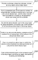
- An implementation of the present disclosure provides a method of manufacturing a semiconductor device. As shown in FIG. 2 , the method of manufacturing a semiconductor device may include the following steps:
- the performing, by using second plasma, a plasma surface treatment on an exposed part of the surface of the amorphous silicon layer 201 can neutralize charges on the surface of the amorphous silicon layer 201, thereby removing impurity particles 2 due to electrostatic adsorption; and on the other hand, can remove a labile compound 3 on the surface of the amorphous silicon layer 201, and form a smooth hard layer on the surface of the amorphous silicon layer 201.
- the amorphous silicon layer 201 on which the plasma surface treatment has been performed and the dry etched silicon dioxide layer 202 are cleaned.
- the method of manufacturing a semiconductor device improves adhesion between the surface of the amorphous silicon layer 201 and the first photoresist layer 30 in the array region 11, such that the amorphous silicon layer 201 can better adhere to the first photoresist layer 30, thereby improving accuracy of pattern transfer during photolithography, avoiding pattern defects, and thus improving quality of the semiconductor device 1.
- a substrate 10 is provided, where the substrate 10 may include a wafer 101 and a first silicon nitride layer 102, a carbon layer 103, and a second silicon nitride layer 104 sequentially laminated on the wafer 101.
- the first silicon nitride layer 102, the carbon layer 103, and the second silicon nitride layer 104 may be formed by using a chemical vapor deposition method.
- a composite layer 20 is formed on the substrate 10, where the composite layer 20 may include an amorphous silicon layer 201 and a silicon dioxide layer 202, and the silicon dioxide layer 202 is located on a surface of the amorphous silicon layer 201 away from the substrate 10.
- a gaseous raw material of amorphous silicon is introduced into the chamber, and the amorphous silicon layer 201 is formed on the substrate 10.
- a gaseous raw material of silica is introduced into the chamber, and the silicon dioxide layer 202 is formed on the amorphous silicon layer 201. In this way, the composite layer 20 can be formed on the substrate 10.
- step S130 the silicon dioxide layer 202 in an array region 11 is dry etched by using first plasma, to expose a part of the surface of the amorphous silicon layer 201 in the array region 11, and the silicon dioxide layer 202 in the array region 11 is dry etched and a preset pattern is formed.
- the method of manufacturing the semiconductor device in this implementation of the present disclosure further includes: ionizing a first gas in a chamber, to form the first plasma, so as to dry etch the silicon dioxide layer 202.
- the first gas may be hexafluorobutadiene (C 4 F 6 ) or octafluorocyclobutane (C 4 F 8 ) with oxygen, that is, the first gas may be a mixed gas of oxygen and octafluorocyclobutane or a mixed gas of oxygen and hexafluorobutadiene.
- step S140 a plasma surface treatment is formed, by using second plasma, on an exposed part of the surface of the amorphous silicon layer 201.
- the surface of the amorphous silicon layer 201 has hydrogen bonds, and positive charges carried by the hydrogen bonds have a certain absorption effect on dust. Therefore, impurity particles 2 are attached to the surface of the amorphous silicon layer 201 (as shown in FIG. 4 ).
- impurity particles 2 are attached to the surface of the amorphous silicon layer 201 (as shown in FIG. 4 ).
- the silicon dioxide layer 202 in the array region 11 is dry etched by using the first plasma, because gas plasma used is a high-energy particle aggregate with high chemical reactivity, particles react with each other and the labile compound 3 is formed (as shown in FIG. 4 ).
- the impurity particles 2 and the labile compound 3 work together, and consequently, the first photoresist layer 30 cannot better adhere to the amorphous silicon layer 201 during a spin coating process. This reduces accuracy of pattern transfer.
- the performing, by using second plasma, a plasma surface treatment on an exposed part of the surface of the amorphous silicon layer 201 can neutralize hydrogen bonds on the surface of the amorphous silicon layer 201, thereby removing impurity particles 2 due to electrostatic adsorption; and on the other hand, can remove the labile compound 3 on the surface of the amorphous silicon layer 201, thereby facilitating adhesion of the first photoresist layer 30.
- the method of manufacturing the semiconductor device in this implementation of the present disclosure may further include: ionizing a second gas in the chamber, to form the second plasma, thereby performing the plasma surface treatment on an exposed part of the surface of the amorphous silicon layer 201.
- the second gas may be nitrous oxide or helium, which is not specially limited herein.
- plasma particles formed by nitrous oxide or helium contain nitrogen, and nitrogen reacts in a superficial layer of the amorphous silicon layer 201 to produce a SiN-like composition, a smooth hard layer is formed on the surface of the amorphous silicon layer 201, which in turn improves adhesion of the first photoresist layer 30 on the amorphous silicon layer 201.
- a gas flow rate of the second gas may be 4000 standard ml/min to 6000 standard ml/min.
- the gas flow rate of the second gas may be 1000 standard ml/min to 3000 standard ml/min.
- a value of radio frequency energy for ionizing the second gas may range from 600 watts to 800 watts, and a value of pressure in the chamber may range from 4 torrs to 6 torrs, such that plasma particles in an actual processing procedure are formed.
- the second gas may be another gas, but a radius of a plasma particle formed after ionization of the gas should not be too large, so as to avoid excessive damage to the amorphous silicon layer 201.
- the second gas may be any one or more of neon, argon, or oxygen, which is not specially limited herein.
- step S150 the amorphous silicon layer 201 on which the plasma surface treatment has been performed and the dry etched silicon dioxide layer 202 are cleaned (as shown in FIG. 6 ).
- Step S150 may include the following steps: Step S1501. Blow across the amorphous silicon layer 201 on which the plasma surface treatment has been performed and the dry etched silicon dioxide layer 202, with a gas.
- Step S1502. Clean, with a liquid, the silicon dioxide layer 202 and the amorphous silicon layer 201, after the gas blows across the silicon dioxide layer and the amorphous silicon layer, thereby removing particle defects on surfaces of the amorphous silicon layer 201 and the silicon dioxide layer 202, thus also improving adhesion between the surface of the amorphous silicon layer 201 and the first photoresist layer 30.
- the gas may be nitrogen or another gas and the liquid may be plasma water, which is not described in detail herein.
- step S160 a first photoresist layer 30 is coated on the composite layer 20 in the edge region 12 and the array region 11 (as shown in FIG. 7 ), and exposing and developing are performed. Because the impurity particles 2 and the labile compound 3 on the surface of the amorphous silicon layer 201 are removed, adhesion between the surface of the amorphous silicon layer 201 and the first photoresist layer 30 in the array region 11 is improved. This improves accuracy of pattern transfer during photolithography and avoids pattern defects.
- a silicon oxide hard mask intermediate layer 40 and a second photoresist layer 50 are sequentially formed on a surface of the first photoresist layer 30 away from the substrate 10, and a second preset pattern is formed on the second photoresist layer 50.
- the manufacturing of the semiconductor device 1 further includes packaging, testing, and a plurality of other steps, but none of them are the focus of the present disclosure. Therefore, no detailed description is provided.
- An implementation of the present disclosure provides a semiconductor device, where the semiconductor device is manufactured by the method of manufacturing a semiconductor device described in any one of the above.
- the semiconductor device may be a chip or a MOS device, and the like, which are not listed herein.
- the semiconductor device and the method of manufacturing a semiconductor device thereof disclosed in the present disclosure can make a treated surface layer better bond with a photoresist, thereby improving accuracy of pattern transfer.
Landscapes
- Drying Of Semiconductors (AREA)
- Physics & Mathematics (AREA)
- Engineering & Computer Science (AREA)
- Plasma & Fusion (AREA)
- Photosensitive Polymer And Photoresist Processing (AREA)
- Materials For Photolithography (AREA)
Abstract
Description
- The present disclosure claims the priority to
Chinese Patent Application No. 202011259983.2, titled "SEMICONDUCTOR DEVICE AND METHOD OF MANUFACTURING SEMICONDUCTOR DEVICE", and filed on November 12, 2020 - The present disclosure relates to, but is not limited to, a semiconductor device and a method of manufacturing a semiconductor device.
- During manufacturing of a semiconductor device, as an important method of pattern transfer, a photolithography process is widely applied. As a size of the semiconductor device continues to shrink, the pattern transfer in the photolithography process is also required to be increasingly accurate. When a photoresist (PR) is coated for exposure in a front-end photolithography process during the manufacturing of the semiconductor device, accuracy of the pattern transfer is not high, reducing quality of the semiconductor device.
- An overview of the subject matter detailed in the present disclosure is provided below, which is not intended to limit the protection scope of the claims.
- The present disclosure provides a semiconductor device and a method of manufacturing semiconductor device, to improve accuracy of pattern transfer.
- According to a first aspect of the present disclosure, a method of manufacturing a semiconductor device is provided, where the method of manufacturing a semiconductor device includes:
- providing a substrate, where the substrate includes an array region and an edge region;
- forming a composite layer on the substrate, where the composite layer includes an amorphous silicon layer and a silicon dioxide layer, and the silicon dioxide layer is located on a surface of the amorphous silicon layer away from the substrate;
- dry etching the silicon dioxide layer in the array region by using first plasma, to expose a part of the surface of the amorphous silicon layer in the array region;
- performing, by using second plasma, a plasma surface treatment on an exposed part of the surface of the amorphous silicon layer;
- cleaning an amorphous silicon layer on which the plasma surface treatment has been performed and a dry etched silicon dioxide layer; and
- coating a first photoresist layer on the composite layer in the edge region and the array region, and performing exposing and developing.
- According to a second aspect of the present disclosure, a semiconductor device is provided and is manufactured by the method of manufacturing a semiconductor device described above.
- Other aspects of the present disclosure are understandable upon reading and understanding of the drawings and detailed description.
- The drawings incorporated into the specification and constituting a part of the specification illustrate the embodiments of the present disclosure, and are used together with the descriptions to explain the principles of the embodiments of the present disclosure. In these drawings, similar reference numerals are used to represent similar elements. The drawings in the following descriptions are some rather than all of the embodiments of the present disclosure. Those skilled in the art may derive other drawings based on these drawings without creative efforts.
-
FIG. 1 is a schematic structural diagram of a semiconductor device. -
FIG. 2 is a schematic flowchart of a method of manufacturing a semiconductor device according to an implementation of the present disclosure. -
FIG. 3 is a schematic diagram of hydrogen bonds on a surface of an amorphous silicon layer. -
FIG. 4 is a schematic diagram of impurity particles and a labile compound on the surface of the amorphous silicon layer. -
FIG. 5 is a schematic diagram of performing, by using second plasma, a plasma surface treatment on an exposed part of the surface of the amorphous silicon layer according to an implementation of the present disclosure. -
FIG. 6 is a schematic diagram of cleaning the amorphous silicon layer on which the plasma surface treatment has been performed and a dry etched silicon dioxide layer according to an implementation of the present disclosure. -
FIG. 7 is a schematic diagram of bonding of a first photoresist layer and an amorphous silicon layer after use of the method of manufacturing a semiconductor device according to an implementation of the present disclosure. - In the
figures: 1 . Semiconductor device; 11. Array region; 12. Edge region; 10. Substrate; 101. Wafer; 102. First silicon nitride layer; 103. Carbon layer; 104. Second silicon nitride layer; 20. Composite layer; 201. Amorphous silicon layer; 202. Silicon dioxide layer; 30. First photoresist layer; 40. Silicon oxide hard mask intermediate layer; 50. Second photoresist layer; 2. Impurity particle; 3. Labile compound. - The technical solutions in the embodiments of the present disclosure are described below clearly and completely with reference to the drawings in the embodiments of the present disclosure. Apparently, the described embodiments are merely part rather than all of the embodiments of the present disclosure. All other embodiments obtained by those skilled in the art based on the embodiments of the present disclosure without creative efforts should fall within the protection scope of the present disclosure. It should be noted that the embodiments in the present disclosure and features in the embodiments may be combined with each other in a non-conflicting manner.
- A photolithography process is an important method of pattern transfer during manufacturing of a semiconductor device, and as a size of the semiconductor device continues to shrink, the pattern transfer in the photolithography process is also required to be increasingly accurate. After a PR is coated in a front-end photolithography process during actual manufacturing of a semiconductor device, a memory cell region of the semiconductor device produces pattern defects, which in turn leads to poor quality of the semiconductor device.
- As shown in
FIG. 1 , thesemiconductor device 1 may be divided into anarray region 11 and anedge region 12, and theedge region 12 may be round or square, or the like, which is not specially limited herein. Thesemiconductor device 1 may include asubstrate 10, acomposite layer 20, a firstphotoresist layer 30, a silicon oxide hard maskintermediate layer 40, and a secondphotoresist layer 50. - The
substrate 10 may include awafer 101 and a firstsilicon nitride layer 102, acarbon layer 103, and a secondsilicon nitride layer 104 sequentially laminated on thewafer 101. Thecomposite layer 20 is formed on a surface of thesubstrate 10. Thecomposite layer 20 includes anamorphous silicon layer 201 and asilicon dioxide layer 202, and thesilicon dioxide layer 202 is located on a surface of theamorphous silicon layer 201 away from thesubstrate 10. - The
silicon dioxide layer 202 in thearray region 11 has a first preset pattern, and a part of the surface of theamorphous silicon layer 201 is exposed. Theamorphous silicon layer 201 and thesilicon dioxide layer 202 in theedge region 12 are flat film layers. - A first
photoresist layer 30 is formed on thecomposite layer 20 in theedge region 12 and thearray region 11, a silicon oxide hard maskintermediate layer 40 and a secondphotoresist layer 50 are sequentially formed on a surface of the firstphotoresist layer 30 away from thesubstrate 10, and the secondphotoresist layer 50 has a second preset pattern. - Because pattern defects are concentrated only in the
array region 11 of thesemiconductor device 1, theedge region 12 of thesemiconductor device 1 has no defect. A difference between thearray region 11 and theedge region 12 mainly lies in that a pattern is obtained through etching by an etching process performed on the silicon dioxide layer 202 (a hard mask layer) in thearray region 11. - It is speculated that a reason for the pattern defects is that there are certain impurities on the surface of the etched
amorphous silicon layer 201, and consequently, thefirst photoresist layer 30 cannot well adhere to theamorphous silicon layer 201 during a spin coating process. This reduces accuracy of pattern transfer and eventually causes pattern defects. - An implementation of the present disclosure provides a method of manufacturing a semiconductor device. As shown in
FIG. 2 , the method of manufacturing a semiconductor device may include the following steps: - Step S110. Provide a substrate, where the substrate includes an array region and an edge region.
- Step S120. Form a composite layer on the substrate, where the composite layer includes an amorphous silicon layer and a silicon dioxide layer, and the silicon dioxide layer is located on a surface of the amorphous silicon layer away from the substrate.
- Step S130. Dry etch the silicon dioxide layer in the array region by using first plasma, to expose a part of the surface of the amorphous silicon layer in the array region.
- Step S140. Perform, by using second plasma, a plasma surface treatment on an exposed part of the surface of the amorphous silicon layer.
- Step S150. Clean the amorphous silicon layer on which the plasma surface treatment has been performed and the dry etched silicon dioxide layer.
- Step S160. Coat a first photoresist layer on the composite layer in the edge region and the array region, and perform exposing and developing.
- The performing, by using second plasma, a plasma surface treatment on an exposed part of the surface of the
amorphous silicon layer 201, on the one hand, can neutralize charges on the surface of theamorphous silicon layer 201, thereby removingimpurity particles 2 due to electrostatic adsorption; and on the other hand, can remove alabile compound 3 on the surface of theamorphous silicon layer 201, and form a smooth hard layer on the surface of theamorphous silicon layer 201. - Subsequently, the
amorphous silicon layer 201 on which the plasma surface treatment has been performed and the dry etchedsilicon dioxide layer 202 are cleaned. The method of manufacturing a semiconductor device improves adhesion between the surface of theamorphous silicon layer 201 and thefirst photoresist layer 30 in thearray region 11, such that theamorphous silicon layer 201 can better adhere to thefirst photoresist layer 30, thereby improving accuracy of pattern transfer during photolithography, avoiding pattern defects, and thus improving quality of thesemiconductor device 1. - A photolithography method provided in an implementation of the present disclosure is described in detail below with reference to the accompanying drawings.
- In step S110, a
substrate 10 is provided, where thesubstrate 10 may include awafer 101 and a firstsilicon nitride layer 102, acarbon layer 103, and a secondsilicon nitride layer 104 sequentially laminated on thewafer 101. The firstsilicon nitride layer 102, thecarbon layer 103, and the secondsilicon nitride layer 104 may be formed by using a chemical vapor deposition method. - In step S120, a
composite layer 20 is formed on thesubstrate 10, where thecomposite layer 20 may include anamorphous silicon layer 201 and asilicon dioxide layer 202, and thesilicon dioxide layer 202 is located on a surface of theamorphous silicon layer 201 away from thesubstrate 10. - A gaseous raw material of amorphous silicon is introduced into the chamber, and the
amorphous silicon layer 201 is formed on thesubstrate 10. A gaseous raw material of silica is introduced into the chamber, and thesilicon dioxide layer 202 is formed on theamorphous silicon layer 201. In this way, thecomposite layer 20 can be formed on thesubstrate 10. - In step S130, the
silicon dioxide layer 202 in anarray region 11 is dry etched by using first plasma, to expose a part of the surface of theamorphous silicon layer 201 in thearray region 11, and thesilicon dioxide layer 202 in thearray region 11 is dry etched and a preset pattern is formed. - Before the
silicon dioxide layer 202 in thearray region 11 is dry etched by using the first plasma, the method of manufacturing the semiconductor device in this implementation of the present disclosure further includes:
ionizing a first gas in a chamber, to form the first plasma, so as to dry etch thesilicon dioxide layer 202. The first gas may be hexafluorobutadiene (C4F6) or octafluorocyclobutane (C4F8) with oxygen, that is, the first gas may be a mixed gas of oxygen and octafluorocyclobutane or a mixed gas of oxygen and hexafluorobutadiene. - In step S140, a plasma surface treatment is formed, by using second plasma, on an exposed part of the surface of the
amorphous silicon layer 201. - As shown in
FIG. 3 , the surface of theamorphous silicon layer 201 has hydrogen bonds, and positive charges carried by the hydrogen bonds have a certain absorption effect on dust. Therefore,impurity particles 2 are attached to the surface of the amorphous silicon layer 201 (as shown inFIG. 4 ). In addition, after thesilicon dioxide layer 202 in thearray region 11 is dry etched by using the first plasma, because gas plasma used is a high-energy particle aggregate with high chemical reactivity, particles react with each other and thelabile compound 3 is formed (as shown inFIG. 4 ). - The
impurity particles 2 and thelabile compound 3 work together, and consequently, thefirst photoresist layer 30 cannot better adhere to theamorphous silicon layer 201 during a spin coating process. This reduces accuracy of pattern transfer. - As shown in
FIG. 5 , the performing, by using second plasma, a plasma surface treatment on an exposed part of the surface of theamorphous silicon layer 201, on the one hand, can neutralize hydrogen bonds on the surface of theamorphous silicon layer 201, thereby removingimpurity particles 2 due to electrostatic adsorption; and on the other hand, can remove thelabile compound 3 on the surface of theamorphous silicon layer 201, thereby facilitating adhesion of thefirst photoresist layer 30. - Before the performing, by using second plasma, a plasma surface treatment on an exposed part of the surface of the
amorphous silicon layer 201, the method of manufacturing the semiconductor device in this implementation of the present disclosure may further include:
ionizing a second gas in the chamber, to form the second plasma, thereby performing the plasma surface treatment on an exposed part of the surface of theamorphous silicon layer 201. The second gas may be nitrous oxide or helium, which is not specially limited herein. - Because plasma particles formed by nitrous oxide or helium contain nitrogen, and nitrogen reacts in a superficial layer of the
amorphous silicon layer 201 to produce a SiN-like composition, a smooth hard layer is formed on the surface of theamorphous silicon layer 201, which in turn improves adhesion of thefirst photoresist layer 30 on theamorphous silicon layer 201. - When the second gas is nitrous oxide, a gas flow rate of the second gas may be 4000 standard ml/min to 6000 standard ml/min. When the second gas is helium, the gas flow rate of the second gas may be 1000 standard ml/min to 3000 standard ml/min. In addition, a value of radio frequency energy for ionizing the second gas may range from 600 watts to 800 watts, and a value of pressure in the chamber may range from 4 torrs to 6 torrs, such that plasma particles in an actual processing procedure are formed.
- Alternatively, the second gas may be another gas, but a radius of a plasma particle formed after ionization of the gas should not be too large, so as to avoid excessive damage to the
amorphous silicon layer 201. For example, the second gas may be any one or more of neon, argon, or oxygen, which is not specially limited herein. - In step S150, the
amorphous silicon layer 201 on which the plasma surface treatment has been performed and the dry etchedsilicon dioxide layer 202 are cleaned (as shown inFIG. 6 ). - Step S150 may include the following steps:
Step S1501. Blow across theamorphous silicon layer 201 on which the plasma surface treatment has been performed and the dry etchedsilicon dioxide layer 202, with a gas. - Step S1502. Clean, with a liquid, the
silicon dioxide layer 202 and theamorphous silicon layer 201, after the gas blows across the silicon dioxide layer and the amorphous silicon layer, thereby removing particle defects on surfaces of theamorphous silicon layer 201 and thesilicon dioxide layer 202, thus also improving adhesion between the surface of theamorphous silicon layer 201 and thefirst photoresist layer 30. - The gas may be nitrogen or another gas and the liquid may be plasma water, which is not described in detail herein.
- In step S160, a
first photoresist layer 30 is coated on thecomposite layer 20 in theedge region 12 and the array region 11 (as shown inFIG. 7 ), and exposing and developing are performed. Because theimpurity particles 2 and thelabile compound 3 on the surface of theamorphous silicon layer 201 are removed, adhesion between the surface of theamorphous silicon layer 201 and thefirst photoresist layer 30 in thearray region 11 is improved. This improves accuracy of pattern transfer during photolithography and avoids pattern defects. - Subsequently, a silicon oxide hard mask
intermediate layer 40 and asecond photoresist layer 50 are sequentially formed on a surface of thefirst photoresist layer 30 away from thesubstrate 10, and a second preset pattern is formed on thesecond photoresist layer 50. The manufacturing of thesemiconductor device 1 further includes packaging, testing, and a plurality of other steps, but none of them are the focus of the present disclosure. Therefore, no detailed description is provided. - An implementation of the present disclosure provides a semiconductor device, where the semiconductor device is manufactured by the method of manufacturing a semiconductor device described in any one of the above. For example, the semiconductor device may be a chip or a MOS device, and the like, which are not listed herein.
- The embodiments or implementations of this specification are described in a progressive manner, and each embodiment focuses on differences from other embodiments. The same or similar parts between the embodiments may refer to each other.
- In the description of the specification, the description with reference to terms such as "an embodiment", "an illustrative embodiment", "some implementations", "an illustrative implementation" and "an example" means that the specific feature, structure, material or feature described in combination with the implementation(s) or example(s) is included in at least one implementation or example of the present disclosure.
- In this specification, the schematic expression of the above terms does not necessarily refer to the same implementation or example. Moreover, the described specific feature, structure, material or characteristic may be combined in an appropriate manner in any one or more implementations or examples.
- It should be noted that in the description of the present disclosure, the terms such as "center", "top", "bottom", "left", "right", "vertical", "horizontal", "inner" and "outer" indicate the orientation or position relationships based on the drawings. These terms are merely intended to facilitate description of the present disclosure and simplify the description, rather than to indicate or imply that the mentioned device or element must have a specific orientation and must be constructed and operated in a specific orientation. Therefore, these terms should not be construed as a limitation to the present disclosure.
- It can be understood that the terms such as "first" and "second" used in the present disclosure can be used to describe various structures, but these structures are not limited by these terms. Instead, these terms are merely intended to distinguish one element from another.
- The same elements in one or more drawings are denoted by similar reference numerals. For the sake of clarity, various parts in the drawings are not drawn to scale. In addition, some well-known parts may not be shown. For the sake of brevity, the structure obtained by implementing multiple steps may be shown in one figure. In order to make the understanding of the present disclosure more clearly, many specific details of the present disclosure, such as the structure, material, size, processing process and technology of the device, are described below. However, as those skilled in the art can understand, the present disclosure may not be implemented according to these specific details.
- Finally, it should be noted that the above embodiments are merely intended to explain the technical solutions of the present disclosure, rather than to limit the present disclosure. Although the present disclosure is described in detail with reference to the above embodiments, those skilled in the art should understand that they may still modify the technical solutions described in the above embodiments, or make equivalent substitutions of some or all of the technical features recorded therein, without deviating the essence of the corresponding technical solutions from the scope of the technical solutions of the embodiments of the present disclosure.
- The semiconductor device and the method of manufacturing a semiconductor device thereof disclosed in the present disclosure can make a treated surface layer better bond with a photoresist, thereby improving accuracy of pattern transfer.
Claims (10)
- A method of manufacturing a semiconductor device, comprising:
providing a substrate, wherein the substrate comprises an array region and an edge region;forming a composite layer on the substrate, wherein the composite layer comprises an amorphous silicon layer and a silicon dioxide layer, and the silicon dioxide layer is located on a surface of the amorphous silicon layer away from the substrate;dry etching the silicon dioxide layer in the array region by using first plasma, to expose a part of the surface of the amorphous silicon layer in the array region;performing, by using second plasma, a plasma surface treatment on an exposed part of the surface of the amorphous silicon layer;cleaning an amorphous silicon layer on which the plasma surface treatment has been performed and a dry etched silicon dioxide layer; andcoating a first photoresist layer on the composite layer in the edge region and the array region, and performing exposing and developing. - The method of manufacturing a semiconductor device according to claim 1, wherein the cleaning an amorphous silicon layer on which the plasma surface treatment has been performed and a dry etched silicon dioxide layer comprises:blowing across the amorphous silicon layer on which the plasma surface treatment has been performed and the dry etched silicon dioxide layer, with a gas; andcleaning, with a liquid, the silicon dioxide layer and the amorphous silicon layer, after the gas blows across the silicon dioxide layer and the amorphous silicon layer.
- The method of manufacturing a semiconductor device according to claim 2, wherein the gas is nitrogen, and the liquid is plasma water.
- The method of manufacturing a semiconductor device according to claim 1, wherein before the dry etching the silicon dioxide layer in the array region by using first plasma, the method of manufacturing a semiconductor device further comprises:
ionizing a first gas in a chamber, to form the first plasma, wherein the first gas is a mixed gas of oxygen and hexafluorobutadiene or a mixed gas of oxygen and octafluorocyclobutane. - The method of manufacturing a semiconductor device according to claim 4, wherein before the performing, by using second plasma, a plasma surface treatment on an exposed part of the surface of the amorphous silicon layer, the method of manufacturing a semiconductor device further comprises:
ionizing a second gas in the chamber, to form the second plasma, wherein the second gas is nitrous oxide or helium. - The method of manufacturing a semiconductor device according to claim 5, wherein when the second gas is nitrous oxide, a gas flow rate of the second gas is 4000 standard ml/min to 6000 standard ml/min; and
when the second gas is helium, a gas flow rate of the second gas is 1000 standard ml/min to 3000 standard ml/min. - The method of manufacturing a semiconductor device according to claim 5, wherein a value of radio frequency energy for ionizing the second gas ranges from 600 watts to 800 watts.
- The method of manufacturing a semiconductor device according to claim 5, wherein a value of pressure in the chamber ranges from 4 torrs to 6 torrs.
- The method of manufacturing a semiconductor device according to claim 5, wherein the second gas is any one or more of neon, argon, or oxygen.
- A semiconductor device, manufactured by the method of manufacturing a semiconductor device according to any one of claims 1 to 9.
Applications Claiming Priority (2)
| Application Number | Priority Date | Filing Date | Title |
|---|---|---|---|
| CN202011259983.2A CN114496737B (en) | 2020-11-12 | 2020-11-12 | Semiconductor device and method for manufacturing the same |
| PCT/CN2021/110066 WO2022100158A1 (en) | 2020-11-12 | 2021-08-02 | Semiconductor device and fabrication method therefor |
Publications (3)
| Publication Number | Publication Date |
|---|---|
| EP4020526A1 true EP4020526A1 (en) | 2022-06-29 |
| EP4020526A4 EP4020526A4 (en) | 2023-03-22 |
| EP4020526B1 EP4020526B1 (en) | 2024-05-22 |
Family
ID=81490534
Family Applications (1)
| Application Number | Title | Priority Date | Filing Date |
|---|---|---|---|
| EP21865347.5A Active EP4020526B1 (en) | 2020-11-12 | 2021-08-02 | Semiconductor fabrication method |
Country Status (4)
| Country | Link |
|---|---|
| US (1) | US20230055587A1 (en) |
| EP (1) | EP4020526B1 (en) |
| CN (1) | CN114496737B (en) |
| WO (1) | WO2022100158A1 (en) |
Families Citing this family (1)
| Publication number | Priority date | Publication date | Assignee | Title |
|---|---|---|---|---|
| CN119522151A (en) * | 2022-08-02 | 2025-02-25 | 应用材料公司 | Cleaning of CMP Temperature Control System |
Family Cites Families (22)
| Publication number | Priority date | Publication date | Assignee | Title |
|---|---|---|---|---|
| KR100208023B1 (en) * | 1996-12-27 | 1999-07-15 | 윤종용 | Method of manufacturing thin film transistor |
| US6090672A (en) * | 1998-07-22 | 2000-07-18 | Wanlass; Frank M. | Ultra short channel damascene MOS transistors |
| US6623653B2 (en) * | 2001-06-12 | 2003-09-23 | Sharp Laboratories Of America, Inc. | System and method for etching adjoining layers of silicon and indium tin oxide |
| US7078334B1 (en) * | 2002-06-06 | 2006-07-18 | Cypress Semiconductor Corporation | In situ hard mask approach for self-aligned contact etch |
| JP4661753B2 (en) * | 2006-09-29 | 2011-03-30 | 東京エレクトロン株式会社 | Substrate processing method, cleaning method, and storage medium |
| JP4756063B2 (en) * | 2008-08-15 | 2011-08-24 | 株式会社東芝 | Manufacturing method of semiconductor device |
| US8415212B2 (en) * | 2010-03-11 | 2013-04-09 | Freescale Semiconductor, Inc. | Method of enhancing photoresist adhesion to rare earth oxides |
| JP2012213967A (en) * | 2011-04-01 | 2012-11-08 | Seiko Epson Corp | Method for manufacturing liquid ejection head |
| CN102205942B (en) * | 2011-05-13 | 2015-11-04 | 上海集成电路研发中心有限公司 | MEMS sacrificial layer structure making process |
| US8766090B2 (en) * | 2012-03-19 | 2014-07-01 | Rec Solar Pte. Ltd. | Method for metallization or metallization and interconnection of back contact solar cells |
| US8980762B2 (en) * | 2012-08-31 | 2015-03-17 | Kabushiki Kaisha Toshiba | Method for manufacturing semiconductor device |
| US9761743B2 (en) * | 2013-03-28 | 2017-09-12 | Sharp Kabushiki Kaisha | Photoelectric conversion element |
| CN103972050A (en) * | 2014-05-14 | 2014-08-06 | 京东方科技集团股份有限公司 | Preparation method of polycrystalline silicon thin film, polycrystalline silicon thin film transistor and array substrate |
| CN105390433A (en) * | 2014-09-05 | 2016-03-09 | 中国科学院微电子研究所 | Semiconductor device manufacturing method |
| CN105185838B (en) * | 2015-09-25 | 2019-03-15 | 武汉华星光电技术有限公司 | Thin film transistor and method of manufacturing the same |
| US9876015B1 (en) * | 2017-02-16 | 2018-01-23 | International Business Machines Corporation | Tight pitch inverter using vertical transistors |
| US10312073B2 (en) * | 2017-04-28 | 2019-06-04 | Taiwan Semiconductor Manufacturing Company, Ltd. | Selective removal of carbon-containing and nitrogen-containing silicon residues |
| US10861698B2 (en) * | 2017-08-29 | 2020-12-08 | Taiwan Semiconductor Manufacturing Co., Ltd. | Pattern fidelity enhancement |
| CN107658267B (en) * | 2017-09-15 | 2020-11-06 | 惠科股份有限公司 | Manufacturing method of array substrate |
| US10679853B2 (en) * | 2018-02-08 | 2020-06-09 | International Business Machines Corporation | Self-aligned, over etched hard mask fabrication method and structure |
| CN108364866B (en) * | 2018-02-09 | 2020-10-09 | 信利(惠州)智能显示有限公司 | Amorphous silicon surface treatment method |
| CN111074242A (en) * | 2018-10-19 | 2020-04-28 | 长鑫存储技术有限公司 | Adjusting method of heating device, heating device and chemical vapor deposition equipment |
-
2020
- 2020-11-12 CN CN202011259983.2A patent/CN114496737B/en active Active
-
2021
- 2021-08-02 US US17/594,537 patent/US20230055587A1/en not_active Abandoned
- 2021-08-02 WO PCT/CN2021/110066 patent/WO2022100158A1/en not_active Ceased
- 2021-08-02 EP EP21865347.5A patent/EP4020526B1/en active Active
Also Published As
| Publication number | Publication date |
|---|---|
| WO2022100158A1 (en) | 2022-05-19 |
| EP4020526B1 (en) | 2024-05-22 |
| EP4020526A4 (en) | 2023-03-22 |
| CN114496737A (en) | 2022-05-13 |
| CN114496737B (en) | 2024-09-13 |
| US20230055587A1 (en) | 2023-02-23 |
Similar Documents
| Publication | Publication Date | Title |
|---|---|---|
| JP7401593B2 (en) | Systems and methods for forming voids | |
| US6849556B2 (en) | Etching method, gate etching method, and method of manufacturing semiconductor devices | |
| CN104347389B (en) | Method for etching plasma | |
| TW201611113A (en) | Plasma processing method | |
| JPH0464177B2 (en) | ||
| CN101726993A (en) | Bi-layer, tri-layer mask CD control | |
| US12100601B2 (en) | Etching method with metal hard mask | |
| US10224211B2 (en) | Etching method | |
| KR101877827B1 (en) | Etching gas and etching method | |
| EP4020526B1 (en) | Semiconductor fabrication method | |
| US20030068444A1 (en) | Method to solve particle performance of FSG layer by using UFU season film for FSG process | |
| CN114068273B (en) | Component, preparation method thereof and plasma reaction device | |
| TWI900813B (en) | BIAS VOLTAGE MODULATION APPROACH FOR SiO/SiN LAYER ALTERNATING ETCH PROCESS | |
| JPS63117423A (en) | Method of etching silicon dioxide | |
| US20100133233A1 (en) | Dry etching method | |
| CN102903667B (en) | The formation method of semiconductor devices | |
| TW202410176A (en) | Hardmask for high aspect ratio dielectric etch at cryo and elevated temperatures | |
| JP7382578B2 (en) | Plasma processing method and device chip manufacturing method | |
| JPH11243080A (en) | Etching method of semiconductor substrate | |
| JPH11317396A (en) | Etching equipment | |
| TW202201760A (en) | Raised pad formations for contacts in three-dimensional structures on microelectronic workpieces | |
| JPH05109702A (en) | Method for manufacturing semiconductor device | |
| JP2005251814A (en) | Dry etching method and apparatus of interlayer insulation film | |
| US6183819B1 (en) | Method for processing a poly defect | |
| US20080160773A1 (en) | Method of fabricating semiconductor device |
Legal Events
| Date | Code | Title | Description |
|---|---|---|---|
| STAA | Information on the status of an ep patent application or granted ep patent |
Free format text: STATUS: UNKNOWN |
|
| STAA | Information on the status of an ep patent application or granted ep patent |
Free format text: STATUS: THE INTERNATIONAL PUBLICATION HAS BEEN MADE |
|
| PUAI | Public reference made under article 153(3) epc to a published international application that has entered the european phase |
Free format text: ORIGINAL CODE: 0009012 |
|
| STAA | Information on the status of an ep patent application or granted ep patent |
Free format text: STATUS: REQUEST FOR EXAMINATION WAS MADE |
|
| 17P | Request for examination filed |
Effective date: 20220317 |
|
| AK | Designated contracting states |
Kind code of ref document: A1 Designated state(s): AL AT BE BG CH CY CZ DE DK EE ES FI FR GB GR HR HU IE IS IT LI LT LU LV MC MK MT NL NO PL PT RO RS SE SI SK SM TR |
|
| A4 | Supplementary search report drawn up and despatched |
Effective date: 20230222 |
|
| RIC1 | Information provided on ipc code assigned before grant |
Ipc: H01L 21/02 20060101AFI20230216BHEP |
|
| STAA | Information on the status of an ep patent application or granted ep patent |
Free format text: STATUS: EXAMINATION IS IN PROGRESS |
|
| 17Q | First examination report despatched |
Effective date: 20231103 |
|
| REG | Reference to a national code |
Ref country code: DE Ref legal event code: R079 Free format text: PREVIOUS MAIN CLASS: H01L0021020000 Ipc: H01L0021033000 Ref country code: DE Ref legal event code: R079 Ref document number: 602021013672 Country of ref document: DE Free format text: PREVIOUS MAIN CLASS: H01L0021020000 Ipc: H01L0021033000 |
|
| DAV | Request for validation of the european patent (deleted) | ||
| DAX | Request for extension of the european patent (deleted) | ||
| GRAP | Despatch of communication of intention to grant a patent |
Free format text: ORIGINAL CODE: EPIDOSNIGR1 |
|
| STAA | Information on the status of an ep patent application or granted ep patent |
Free format text: STATUS: GRANT OF PATENT IS INTENDED |
|
| RIC1 | Information provided on ipc code assigned before grant |
Ipc: H01L 21/311 20060101ALI20240219BHEP Ipc: H01L 21/033 20060101AFI20240219BHEP |
|
| INTG | Intention to grant announced |
Effective date: 20240311 |
|
| GRAS | Grant fee paid |
Free format text: ORIGINAL CODE: EPIDOSNIGR3 |
|
| GRAA | (expected) grant |
Free format text: ORIGINAL CODE: 0009210 |
|
| STAA | Information on the status of an ep patent application or granted ep patent |
Free format text: STATUS: THE PATENT HAS BEEN GRANTED |
|
| P01 | Opt-out of the competence of the unified patent court (upc) registered |
Effective date: 20240405 |
|
| AK | Designated contracting states |
Kind code of ref document: B1 Designated state(s): AL AT BE BG CH CY CZ DE DK EE ES FI FR GB GR HR HU IE IS IT LI LT LU LV MC MK MT NL NO PL PT RO RS SE SI SK SM TR |
|
| REG | Reference to a national code |
Ref country code: GB Ref legal event code: FG4D |
|
| REG | Reference to a national code |
Ref country code: CH Ref legal event code: EP |
|
| REG | Reference to a national code |
Ref country code: DE Ref legal event code: R096 Ref document number: 602021013672 Country of ref document: DE |
|
| REG | Reference to a national code |
Ref country code: IE Ref legal event code: FG4D |
|
| REG | Reference to a national code |
Ref country code: LT Ref legal event code: MG9D |
|
| REG | Reference to a national code |
Ref country code: NL Ref legal event code: MP Effective date: 20240522 |
|
| PG25 | Lapsed in a contracting state [announced via postgrant information from national office to epo] |
Ref country code: IS Free format text: LAPSE BECAUSE OF FAILURE TO SUBMIT A TRANSLATION OF THE DESCRIPTION OR TO PAY THE FEE WITHIN THE PRESCRIBED TIME-LIMIT Effective date: 20240922 |
|
| PG25 | Lapsed in a contracting state [announced via postgrant information from national office to epo] |
Ref country code: BG Free format text: LAPSE BECAUSE OF FAILURE TO SUBMIT A TRANSLATION OF THE DESCRIPTION OR TO PAY THE FEE WITHIN THE PRESCRIBED TIME-LIMIT Effective date: 20240522 |
|
| PG25 | Lapsed in a contracting state [announced via postgrant information from national office to epo] |
Ref country code: HR Free format text: LAPSE BECAUSE OF FAILURE TO SUBMIT A TRANSLATION OF THE DESCRIPTION OR TO PAY THE FEE WITHIN THE PRESCRIBED TIME-LIMIT Effective date: 20240522 Ref country code: FI Free format text: LAPSE BECAUSE OF FAILURE TO SUBMIT A TRANSLATION OF THE DESCRIPTION OR TO PAY THE FEE WITHIN THE PRESCRIBED TIME-LIMIT Effective date: 20240522 |
|
| PG25 | Lapsed in a contracting state [announced via postgrant information from national office to epo] |
Ref country code: GR Free format text: LAPSE BECAUSE OF FAILURE TO SUBMIT A TRANSLATION OF THE DESCRIPTION OR TO PAY THE FEE WITHIN THE PRESCRIBED TIME-LIMIT Effective date: 20240823 |
|
| PG25 | Lapsed in a contracting state [announced via postgrant information from national office to epo] |
Ref country code: PT Free format text: LAPSE BECAUSE OF FAILURE TO SUBMIT A TRANSLATION OF THE DESCRIPTION OR TO PAY THE FEE WITHIN THE PRESCRIBED TIME-LIMIT Effective date: 20240923 |
|
| REG | Reference to a national code |
Ref country code: AT Ref legal event code: MK05 Ref document number: 1689476 Country of ref document: AT Kind code of ref document: T Effective date: 20240522 |
|
| PG25 | Lapsed in a contracting state [announced via postgrant information from national office to epo] |
Ref country code: NL Free format text: LAPSE BECAUSE OF FAILURE TO SUBMIT A TRANSLATION OF THE DESCRIPTION OR TO PAY THE FEE WITHIN THE PRESCRIBED TIME-LIMIT Effective date: 20240522 |
|
| PG25 | Lapsed in a contracting state [announced via postgrant information from national office to epo] |
Ref country code: ES Free format text: LAPSE BECAUSE OF FAILURE TO SUBMIT A TRANSLATION OF THE DESCRIPTION OR TO PAY THE FEE WITHIN THE PRESCRIBED TIME-LIMIT Effective date: 20240522 |
|
| PG25 | Lapsed in a contracting state [announced via postgrant information from national office to epo] |
Ref country code: AT Free format text: LAPSE BECAUSE OF FAILURE TO SUBMIT A TRANSLATION OF THE DESCRIPTION OR TO PAY THE FEE WITHIN THE PRESCRIBED TIME-LIMIT Effective date: 20240522 |
|
| PG25 | Lapsed in a contracting state [announced via postgrant information from national office to epo] |
Ref country code: PL Free format text: LAPSE BECAUSE OF FAILURE TO SUBMIT A TRANSLATION OF THE DESCRIPTION OR TO PAY THE FEE WITHIN THE PRESCRIBED TIME-LIMIT Effective date: 20240522 |
|
| PG25 | Lapsed in a contracting state [announced via postgrant information from national office to epo] |
Ref country code: LV Free format text: LAPSE BECAUSE OF FAILURE TO SUBMIT A TRANSLATION OF THE DESCRIPTION OR TO PAY THE FEE WITHIN THE PRESCRIBED TIME-LIMIT Effective date: 20240522 |
|
| PG25 | Lapsed in a contracting state [announced via postgrant information from national office to epo] |
Ref country code: PT Free format text: LAPSE BECAUSE OF FAILURE TO SUBMIT A TRANSLATION OF THE DESCRIPTION OR TO PAY THE FEE WITHIN THE PRESCRIBED TIME-LIMIT Effective date: 20240923 Ref country code: PL Free format text: LAPSE BECAUSE OF FAILURE TO SUBMIT A TRANSLATION OF THE DESCRIPTION OR TO PAY THE FEE WITHIN THE PRESCRIBED TIME-LIMIT Effective date: 20240522 Ref country code: NO Free format text: LAPSE BECAUSE OF FAILURE TO SUBMIT A TRANSLATION OF THE DESCRIPTION OR TO PAY THE FEE WITHIN THE PRESCRIBED TIME-LIMIT Effective date: 20240822 Ref country code: NL Free format text: LAPSE BECAUSE OF FAILURE TO SUBMIT A TRANSLATION OF THE DESCRIPTION OR TO PAY THE FEE WITHIN THE PRESCRIBED TIME-LIMIT Effective date: 20240522 Ref country code: LV Free format text: LAPSE BECAUSE OF FAILURE TO SUBMIT A TRANSLATION OF THE DESCRIPTION OR TO PAY THE FEE WITHIN THE PRESCRIBED TIME-LIMIT Effective date: 20240522 Ref country code: IS Free format text: LAPSE BECAUSE OF FAILURE TO SUBMIT A TRANSLATION OF THE DESCRIPTION OR TO PAY THE FEE WITHIN THE PRESCRIBED TIME-LIMIT Effective date: 20240922 Ref country code: HR Free format text: LAPSE BECAUSE OF FAILURE TO SUBMIT A TRANSLATION OF THE DESCRIPTION OR TO PAY THE FEE WITHIN THE PRESCRIBED TIME-LIMIT Effective date: 20240522 Ref country code: GR Free format text: LAPSE BECAUSE OF FAILURE TO SUBMIT A TRANSLATION OF THE DESCRIPTION OR TO PAY THE FEE WITHIN THE PRESCRIBED TIME-LIMIT Effective date: 20240823 Ref country code: FI Free format text: LAPSE BECAUSE OF FAILURE TO SUBMIT A TRANSLATION OF THE DESCRIPTION OR TO PAY THE FEE WITHIN THE PRESCRIBED TIME-LIMIT Effective date: 20240522 Ref country code: ES Free format text: LAPSE BECAUSE OF FAILURE TO SUBMIT A TRANSLATION OF THE DESCRIPTION OR TO PAY THE FEE WITHIN THE PRESCRIBED TIME-LIMIT Effective date: 20240522 Ref country code: BG Free format text: LAPSE BECAUSE OF FAILURE TO SUBMIT A TRANSLATION OF THE DESCRIPTION OR TO PAY THE FEE WITHIN THE PRESCRIBED TIME-LIMIT Effective date: 20240522 Ref country code: AT Free format text: LAPSE BECAUSE OF FAILURE TO SUBMIT A TRANSLATION OF THE DESCRIPTION OR TO PAY THE FEE WITHIN THE PRESCRIBED TIME-LIMIT Effective date: 20240522 Ref country code: RS Free format text: LAPSE BECAUSE OF FAILURE TO SUBMIT A TRANSLATION OF THE DESCRIPTION OR TO PAY THE FEE WITHIN THE PRESCRIBED TIME-LIMIT Effective date: 20240822 |
|
| PG25 | Lapsed in a contracting state [announced via postgrant information from national office to epo] |
Ref country code: DK Free format text: LAPSE BECAUSE OF FAILURE TO SUBMIT A TRANSLATION OF THE DESCRIPTION OR TO PAY THE FEE WITHIN THE PRESCRIBED TIME-LIMIT Effective date: 20240522 |
|
| PG25 | Lapsed in a contracting state [announced via postgrant information from national office to epo] |
Ref country code: EE Free format text: LAPSE BECAUSE OF FAILURE TO SUBMIT A TRANSLATION OF THE DESCRIPTION OR TO PAY THE FEE WITHIN THE PRESCRIBED TIME-LIMIT Effective date: 20240522 |
|
| PG25 | Lapsed in a contracting state [announced via postgrant information from national office to epo] |
Ref country code: CZ Free format text: LAPSE BECAUSE OF FAILURE TO SUBMIT A TRANSLATION OF THE DESCRIPTION OR TO PAY THE FEE WITHIN THE PRESCRIBED TIME-LIMIT Effective date: 20240522 |
|
| PG25 | Lapsed in a contracting state [announced via postgrant information from national office to epo] |
Ref country code: SK Free format text: LAPSE BECAUSE OF FAILURE TO SUBMIT A TRANSLATION OF THE DESCRIPTION OR TO PAY THE FEE WITHIN THE PRESCRIBED TIME-LIMIT Effective date: 20240522 Ref country code: RO Free format text: LAPSE BECAUSE OF FAILURE TO SUBMIT A TRANSLATION OF THE DESCRIPTION OR TO PAY THE FEE WITHIN THE PRESCRIBED TIME-LIMIT Effective date: 20240522 |
|
| PG25 | Lapsed in a contracting state [announced via postgrant information from national office to epo] |
Ref country code: SK Free format text: LAPSE BECAUSE OF FAILURE TO SUBMIT A TRANSLATION OF THE DESCRIPTION OR TO PAY THE FEE WITHIN THE PRESCRIBED TIME-LIMIT Effective date: 20240522 Ref country code: RO Free format text: LAPSE BECAUSE OF FAILURE TO SUBMIT A TRANSLATION OF THE DESCRIPTION OR TO PAY THE FEE WITHIN THE PRESCRIBED TIME-LIMIT Effective date: 20240522 Ref country code: EE Free format text: LAPSE BECAUSE OF FAILURE TO SUBMIT A TRANSLATION OF THE DESCRIPTION OR TO PAY THE FEE WITHIN THE PRESCRIBED TIME-LIMIT Effective date: 20240522 Ref country code: DK Free format text: LAPSE BECAUSE OF FAILURE TO SUBMIT A TRANSLATION OF THE DESCRIPTION OR TO PAY THE FEE WITHIN THE PRESCRIBED TIME-LIMIT Effective date: 20240522 Ref country code: CZ Free format text: LAPSE BECAUSE OF FAILURE TO SUBMIT A TRANSLATION OF THE DESCRIPTION OR TO PAY THE FEE WITHIN THE PRESCRIBED TIME-LIMIT Effective date: 20240522 |
|
| PG25 | Lapsed in a contracting state [announced via postgrant information from national office to epo] |
Ref country code: IT Free format text: LAPSE BECAUSE OF FAILURE TO SUBMIT A TRANSLATION OF THE DESCRIPTION OR TO PAY THE FEE WITHIN THE PRESCRIBED TIME-LIMIT Effective date: 20240522 |
|
| REG | Reference to a national code |
Ref country code: DE Ref legal event code: R097 Ref document number: 602021013672 Country of ref document: DE |
|
| PLBE | No opposition filed within time limit |
Free format text: ORIGINAL CODE: 0009261 |
|
| STAA | Information on the status of an ep patent application or granted ep patent |
Free format text: STATUS: NO OPPOSITION FILED WITHIN TIME LIMIT |
|
| REG | Reference to a national code |
Ref country code: CH Ref legal event code: PL |
|
| PG25 | Lapsed in a contracting state [announced via postgrant information from national office to epo] |
Ref country code: LU Free format text: LAPSE BECAUSE OF NON-PAYMENT OF DUE FEES Effective date: 20240802 |
|
| PG25 | Lapsed in a contracting state [announced via postgrant information from national office to epo] |
Ref country code: SI Free format text: LAPSE BECAUSE OF FAILURE TO SUBMIT A TRANSLATION OF THE DESCRIPTION OR TO PAY THE FEE WITHIN THE PRESCRIBED TIME-LIMIT Effective date: 20240522 Ref country code: CH Free format text: LAPSE BECAUSE OF NON-PAYMENT OF DUE FEES Effective date: 20240831 Ref country code: MC Free format text: LAPSE BECAUSE OF FAILURE TO SUBMIT A TRANSLATION OF THE DESCRIPTION OR TO PAY THE FEE WITHIN THE PRESCRIBED TIME-LIMIT Effective date: 20240522 |
|
| 26N | No opposition filed |
Effective date: 20250225 |
|
| REG | Reference to a national code |
Ref country code: BE Ref legal event code: MM Effective date: 20240831 |
|
| PG25 | Lapsed in a contracting state [announced via postgrant information from national office to epo] |
Ref country code: BE Free format text: LAPSE BECAUSE OF NON-PAYMENT OF DUE FEES Effective date: 20240831 |
|
| PG25 | Lapsed in a contracting state [announced via postgrant information from national office to epo] |
Ref country code: FR Free format text: LAPSE BECAUSE OF NON-PAYMENT OF DUE FEES Effective date: 20240831 |
|
| PG25 | Lapsed in a contracting state [announced via postgrant information from national office to epo] |
Ref country code: IE Free format text: LAPSE BECAUSE OF NON-PAYMENT OF DUE FEES Effective date: 20240802 |
|
| PG25 | Lapsed in a contracting state [announced via postgrant information from national office to epo] |
Ref country code: SE Free format text: LAPSE BECAUSE OF FAILURE TO SUBMIT A TRANSLATION OF THE DESCRIPTION OR TO PAY THE FEE WITHIN THE PRESCRIBED TIME-LIMIT Effective date: 20240522 |
|
| PGFP | Annual fee paid to national office [announced via postgrant information from national office to epo] |
Ref country code: DE Payment date: 20250820 Year of fee payment: 5 |
|
| REG | Reference to a national code |
Ref country code: DE Ref legal event code: R079 Ref document number: 602021013672 Country of ref document: DE Free format text: PREVIOUS MAIN CLASS: H01L0021033000 Ipc: H10P0076400000 |
|
| PG25 | Lapsed in a contracting state [announced via postgrant information from national office to epo] |
Ref country code: SM Free format text: LAPSE BECAUSE OF FAILURE TO SUBMIT A TRANSLATION OF THE DESCRIPTION OR TO PAY THE FEE WITHIN THE PRESCRIBED TIME-LIMIT; INVALID AB INITIO Effective date: 20210802 |
|
| PG25 | Lapsed in a contracting state [announced via postgrant information from national office to epo] |
Ref country code: CY Free format text: LAPSE BECAUSE OF FAILURE TO SUBMIT A TRANSLATION OF THE DESCRIPTION OR TO PAY THE FEE WITHIN THE PRESCRIBED TIME-LIMIT; INVALID AB INITIO Effective date: 20210802 |
|
| PG25 | Lapsed in a contracting state [announced via postgrant information from national office to epo] |
Ref country code: HU Free format text: LAPSE BECAUSE OF FAILURE TO SUBMIT A TRANSLATION OF THE DESCRIPTION OR TO PAY THE FEE WITHIN THE PRESCRIBED TIME-LIMIT; INVALID AB INITIO Effective date: 20210802 |
|
| GBPC | Gb: european patent ceased through non-payment of renewal fee |
Effective date: 20250802 |