EP4020452A1 - Data driving circuit and display device - Google Patents
Data driving circuit and display device Download PDFInfo
- Publication number
- EP4020452A1 EP4020452A1 EP21216943.7A EP21216943A EP4020452A1 EP 4020452 A1 EP4020452 A1 EP 4020452A1 EP 21216943 A EP21216943 A EP 21216943A EP 4020452 A1 EP4020452 A1 EP 4020452A1
- Authority
- EP
- European Patent Office
- Prior art keywords
- voltage
- period
- node
- driving transistor
- drt
- Prior art date
- Legal status (The legal status is an assumption and is not a legal conclusion. Google has not performed a legal analysis and makes no representation as to the accuracy of the status listed.)
- Pending
Links
Images


Classifications
-
- G—PHYSICS
- G09—EDUCATION; CRYPTOGRAPHY; DISPLAY; ADVERTISING; SEALS
- G09G—ARRANGEMENTS OR CIRCUITS FOR CONTROL OF INDICATING DEVICES USING STATIC MEANS TO PRESENT VARIABLE INFORMATION
- G09G3/00—Control arrangements or circuits, of interest only in connection with visual indicators other than cathode-ray tubes
- G09G3/20—Control arrangements or circuits, of interest only in connection with visual indicators other than cathode-ray tubes for presentation of an assembly of a number of characters, e.g. a page, by composing the assembly by combination of individual elements arranged in a matrix no fixed position being assigned to or needed to be assigned to the individual characters or partial characters
- G09G3/22—Control arrangements or circuits, of interest only in connection with visual indicators other than cathode-ray tubes for presentation of an assembly of a number of characters, e.g. a page, by composing the assembly by combination of individual elements arranged in a matrix no fixed position being assigned to or needed to be assigned to the individual characters or partial characters using controlled light sources
- G09G3/30—Control arrangements or circuits, of interest only in connection with visual indicators other than cathode-ray tubes for presentation of an assembly of a number of characters, e.g. a page, by composing the assembly by combination of individual elements arranged in a matrix no fixed position being assigned to or needed to be assigned to the individual characters or partial characters using controlled light sources using electroluminescent panels
- G09G3/32—Control arrangements or circuits, of interest only in connection with visual indicators other than cathode-ray tubes for presentation of an assembly of a number of characters, e.g. a page, by composing the assembly by combination of individual elements arranged in a matrix no fixed position being assigned to or needed to be assigned to the individual characters or partial characters using controlled light sources using electroluminescent panels semiconductive, e.g. using light-emitting diodes [LED]
- G09G3/3208—Control arrangements or circuits, of interest only in connection with visual indicators other than cathode-ray tubes for presentation of an assembly of a number of characters, e.g. a page, by composing the assembly by combination of individual elements arranged in a matrix no fixed position being assigned to or needed to be assigned to the individual characters or partial characters using controlled light sources using electroluminescent panels semiconductive, e.g. using light-emitting diodes [LED] organic, e.g. using organic light-emitting diodes [OLED]
- G09G3/3225—Control arrangements or circuits, of interest only in connection with visual indicators other than cathode-ray tubes for presentation of an assembly of a number of characters, e.g. a page, by composing the assembly by combination of individual elements arranged in a matrix no fixed position being assigned to or needed to be assigned to the individual characters or partial characters using controlled light sources using electroluminescent panels semiconductive, e.g. using light-emitting diodes [LED] organic, e.g. using organic light-emitting diodes [OLED] using an active matrix
- G09G3/3233—Control arrangements or circuits, of interest only in connection with visual indicators other than cathode-ray tubes for presentation of an assembly of a number of characters, e.g. a page, by composing the assembly by combination of individual elements arranged in a matrix no fixed position being assigned to or needed to be assigned to the individual characters or partial characters using controlled light sources using electroluminescent panels semiconductive, e.g. using light-emitting diodes [LED] organic, e.g. using organic light-emitting diodes [OLED] using an active matrix with pixel circuitry controlling the current through the light-emitting element
-
- G—PHYSICS
- G09—EDUCATION; CRYPTOGRAPHY; DISPLAY; ADVERTISING; SEALS
- G09G—ARRANGEMENTS OR CIRCUITS FOR CONTROL OF INDICATING DEVICES USING STATIC MEANS TO PRESENT VARIABLE INFORMATION
- G09G3/00—Control arrangements or circuits, of interest only in connection with visual indicators other than cathode-ray tubes
- G09G3/20—Control arrangements or circuits, of interest only in connection with visual indicators other than cathode-ray tubes for presentation of an assembly of a number of characters, e.g. a page, by composing the assembly by combination of individual elements arranged in a matrix no fixed position being assigned to or needed to be assigned to the individual characters or partial characters
- G09G3/22—Control arrangements or circuits, of interest only in connection with visual indicators other than cathode-ray tubes for presentation of an assembly of a number of characters, e.g. a page, by composing the assembly by combination of individual elements arranged in a matrix no fixed position being assigned to or needed to be assigned to the individual characters or partial characters using controlled light sources
- G09G3/30—Control arrangements or circuits, of interest only in connection with visual indicators other than cathode-ray tubes for presentation of an assembly of a number of characters, e.g. a page, by composing the assembly by combination of individual elements arranged in a matrix no fixed position being assigned to or needed to be assigned to the individual characters or partial characters using controlled light sources using electroluminescent panels
- G09G3/32—Control arrangements or circuits, of interest only in connection with visual indicators other than cathode-ray tubes for presentation of an assembly of a number of characters, e.g. a page, by composing the assembly by combination of individual elements arranged in a matrix no fixed position being assigned to or needed to be assigned to the individual characters or partial characters using controlled light sources using electroluminescent panels semiconductive, e.g. using light-emitting diodes [LED]
- G09G3/3208—Control arrangements or circuits, of interest only in connection with visual indicators other than cathode-ray tubes for presentation of an assembly of a number of characters, e.g. a page, by composing the assembly by combination of individual elements arranged in a matrix no fixed position being assigned to or needed to be assigned to the individual characters or partial characters using controlled light sources using electroluminescent panels semiconductive, e.g. using light-emitting diodes [LED] organic, e.g. using organic light-emitting diodes [OLED]
- G09G3/3275—Details of drivers for data electrodes
-
- G—PHYSICS
- G09—EDUCATION; CRYPTOGRAPHY; DISPLAY; ADVERTISING; SEALS
- G09G—ARRANGEMENTS OR CIRCUITS FOR CONTROL OF INDICATING DEVICES USING STATIC MEANS TO PRESENT VARIABLE INFORMATION
- G09G2300/00—Aspects of the constitution of display devices
- G09G2300/04—Structural and physical details of display devices
- G09G2300/0439—Pixel structures
-
- G—PHYSICS
- G09—EDUCATION; CRYPTOGRAPHY; DISPLAY; ADVERTISING; SEALS
- G09G—ARRANGEMENTS OR CIRCUITS FOR CONTROL OF INDICATING DEVICES USING STATIC MEANS TO PRESENT VARIABLE INFORMATION
- G09G2300/00—Aspects of the constitution of display devices
- G09G2300/08—Active matrix structure, i.e. with use of active elements, inclusive of non-linear two terminal elements, in the pixels together with light emitting or modulating elements
- G09G2300/0809—Several active elements per pixel in active matrix panels
- G09G2300/0819—Several active elements per pixel in active matrix panels used for counteracting undesired variations, e.g. feedback or autozeroing
-
- G—PHYSICS
- G09—EDUCATION; CRYPTOGRAPHY; DISPLAY; ADVERTISING; SEALS
- G09G—ARRANGEMENTS OR CIRCUITS FOR CONTROL OF INDICATING DEVICES USING STATIC MEANS TO PRESENT VARIABLE INFORMATION
- G09G2300/00—Aspects of the constitution of display devices
- G09G2300/08—Active matrix structure, i.e. with use of active elements, inclusive of non-linear two terminal elements, in the pixels together with light emitting or modulating elements
- G09G2300/0809—Several active elements per pixel in active matrix panels
- G09G2300/0842—Several active elements per pixel in active matrix panels forming a memory circuit, e.g. a dynamic memory with one capacitor
-
- G—PHYSICS
- G09—EDUCATION; CRYPTOGRAPHY; DISPLAY; ADVERTISING; SEALS
- G09G—ARRANGEMENTS OR CIRCUITS FOR CONTROL OF INDICATING DEVICES USING STATIC MEANS TO PRESENT VARIABLE INFORMATION
- G09G2310/00—Command of the display device
- G09G2310/02—Addressing, scanning or driving the display screen or processing steps related thereto
- G09G2310/0264—Details of driving circuits
-
- G—PHYSICS
- G09—EDUCATION; CRYPTOGRAPHY; DISPLAY; ADVERTISING; SEALS
- G09G—ARRANGEMENTS OR CIRCUITS FOR CONTROL OF INDICATING DEVICES USING STATIC MEANS TO PRESENT VARIABLE INFORMATION
- G09G2310/00—Command of the display device
- G09G2310/08—Details of timing specific for flat panels, other than clock recovery
-
- G—PHYSICS
- G09—EDUCATION; CRYPTOGRAPHY; DISPLAY; ADVERTISING; SEALS
- G09G—ARRANGEMENTS OR CIRCUITS FOR CONTROL OF INDICATING DEVICES USING STATIC MEANS TO PRESENT VARIABLE INFORMATION
- G09G2320/00—Control of display operating conditions
- G09G2320/02—Improving the quality of display appearance
- G09G2320/029—Improving the quality of display appearance by monitoring one or more pixels in the display panel, e.g. by monitoring a fixed reference pixel
- G09G2320/0295—Improving the quality of display appearance by monitoring one or more pixels in the display panel, e.g. by monitoring a fixed reference pixel by monitoring each display pixel
-
- G—PHYSICS
- G09—EDUCATION; CRYPTOGRAPHY; DISPLAY; ADVERTISING; SEALS
- G09G—ARRANGEMENTS OR CIRCUITS FOR CONTROL OF INDICATING DEVICES USING STATIC MEANS TO PRESENT VARIABLE INFORMATION
- G09G2320/00—Control of display operating conditions
- G09G2320/04—Maintaining the quality of display appearance
- G09G2320/043—Preventing or counteracting the effects of ageing
- G09G2320/045—Compensation of drifts in the characteristics of light emitting or modulating elements
-
- G—PHYSICS
- G09—EDUCATION; CRYPTOGRAPHY; DISPLAY; ADVERTISING; SEALS
- G09G—ARRANGEMENTS OR CIRCUITS FOR CONTROL OF INDICATING DEVICES USING STATIC MEANS TO PRESENT VARIABLE INFORMATION
- G09G2320/00—Control of display operating conditions
- G09G2320/06—Adjustment of display parameters
- G09G2320/0626—Adjustment of display parameters for control of overall brightness
Definitions
- the present disclosure relates to a data driving circuit and a display device.
- the organic light emitting display device utilizes an organic light emitting diode emitting light by itself, so that there may have advantages in the rapid response speed, excellent contrast ratio and high color reproduction.
- the organic light emitting display device may include, for example, an organic light emitting diode disposed in each subpixel, and a driving transistor for supplying a driving current to the organic light emitting diode.
- circuit elements such as organic light emitting diodes and driving transistors disposed in subpixels may deteriorate. Further, a characteristic value of the driving transistor may change due to deterioration of the driving transistor.
- the characteristic values of the driving transistors change, there may occur deviations in characteristic values between the driving transistors disposed in the subpixels, so that the driving current supplied to the organic light emitting diode by the driving transistor may not be accurately controlled.
- Embodiments of the present disclosure may provide a manner capable of compensating the change in characteristic value due to deterioration of a driving transistor supplying a driving current to a light emitting device disposed in a subpixel by a circuit structure and driving method of the subpixel.
- Embodiments of the present disclosure may provide a manner capable of improving an accuracy of compensation in compensating for changes in characteristic values due to deterioration of the driving transistor by the circuit structure and driving method of the subpixel.
- embodiments of the present disclosure may provide a display device including a display panel on which a plurality of subpixels are disposed, and a data driving circuit supplying a data voltage to the plurality of subpixels.
- Each of the plurality of subpixels may include a light emitting device, a driving transistor for driving the light emitting device, and a storage capacitor electrically connected between a first node and a second node of the driving transistor.
- the data driving circuit may detect, in an external sensing period, a change value of a threshold voltage of the driving transistor included in at least one of the plurality of subpixels.
- the data driving circuit may supply, in a display period, the data voltage obtained by adding a first voltage corresponding to a luminance of the light emitting device and a second voltage smaller than the change value of the threshold voltage of the driving transistor to at least one subpixel of the plurality of subpixels.
- a display device may comprise a display panel on which a plurality of subpixels, a plurality of gate lines and a plurality of data lines are disposed, wherein each subpixel is positioned in a region, where one of the plurality of gate lines intersects with one of the plurality of data lines; and a data driving circuit configured to supply a data voltage to each of the data lines, wherein each of the plurality of subpixels emit light having a brightness according to the supplied data voltage, wherein each of the plurality of subpixels comprises a light emitting device; a subpixel circuit comprising: a driving transistor configured to drive the light emitting device and a storage capacitor electrically connected between a first node and a second node of the driving transistor, wherein the data driving circuit is configured to detect, in an external sensing period, a change value of a threshold voltage of the driving transistor included in at least one of the plurality of subpixels, and to supply, in a display period, the data voltage obtained by adding a first voltage corresponding to a lumina
- the second voltage may be a value obtained by multiplying the change value of the threshold voltage of the driving transistor by a boosting loss ratio.
- the boosting loss ratio may be a value obtained by subtracting a boosting remain ratio from 1.
- the boosting remain ratio may be a ratio of a change value of a voltage of the second node of the driving transistor in a light emission period of the display period with respect to a change value of a voltage of the second node configured based on a difference between a voltage of the first node and a voltage of the second node of the driving transistor in a data writing period of the display period.
- the boosting remain ratio may be a ratio of a capacitance by the storage capacitor to a sum of a parasitic capacitance formed by the first node of the driving transistor and the capacitance by the storage capacitor.
- embodiments of the present disclosure may provide a display device including a display panel on which a plurality of subpixels including a light emitting device and a driving transistor for driving the light emitting device are disposed, and a data driving circuit for supplying a data voltage to the plurality of subpixels.
- the data driving circuit may supply, in a display period, the data voltage obtained by adding a first voltage corresponding to a luminance of the light emitting device and a second voltage smaller than a change value of a threshold voltage of the driving transistor to at least one subpixel of the plurality of subpixels.
- embodiments of the present disclosure may provide a data driving circuit including a sensing unit configured to detect a change value of a threshold voltage of a driving transistor included in at least one of a plurality of subpixels in an external sensing period, and a data voltage output unit configured to supply, in a display period, a data voltage obtained by adding a first voltage corresponding to a luminance of the subpixel and a second voltage smaller than the change value of a threshold voltage of the driving transistor to at least one subpixel of the plurality of subpixels.
- a voltage difference between a gate node and a source node of the driving transistor corresponds to the changed threshold voltage of the driving transistor, so that it is possible to compensate a change in the characteristic value of a driving transistor during the driving process of the subpixel.
- a data voltage including a voltage capable of compensating for a loss of a change value of a threshold voltage of the driving transistor in a data writing period of the display period, so that it is possible to prevent loss of the change value of the threshold voltage of the driving transistor during a boosting period.
- the present disclosure in compensating for the change value of the characteristic value of the driving transistor disposed in the subpixel by an internal compensation method, by supplying a voltage including a loss compensation voltage calculated based on the change value of the characteristic value of the driving transistor to the subpixel, it is possible to prevent the compensation value reflected by the internal compensation from being lost in a boosting period after an internal compensation period and to improve the accuracy of the internal compensation.
- first element is connected or coupled to
- overlaps etc. a second element
- the second element may be included in at least one of two or more elements that "are connected or coupled to", “contact or overlap”, etc. each other.
- FIG. 1 schematically illustrates a configuration included in a display device 100 according to embodiments of the present disclosure.
- the display device 100 may include a display panel 110, a gate driving circuit 120 and a data driving circuit 130 for driving the display panel 110, a controller 140, or the like.
- the display panel 110 a plurality of subpixels SP is disposed.
- the display panel 110 may include an active area AA in which the plurality of subpixels SP are disposed, and a non-active area NA positioned outside the active area AA.
- a plurality of gate lines GL and a plurality of data lines DL may be disposed on the display panel 110.
- the subpixel SP may be positioned in a region where the gate line GL and the data line DL intersect.
- the gate driving circuit 120 is controlled by the controller 140.
- the gate driving circuit 120 can sequentially output scan signals to the plurality of gate lines GL arranged on the display panel 110, thereby controlling the driving timing of the plurality of subpixels SP.
- the gate driving circuit 120 may include one or more gate driver integrated circuits GDIC.
- the gate driving circuit 120 may be located only at one side of the display panel 110, or can be located at both sides thereof according to a driving method.
- Each gate driver integrated circuit GDIC may be connected to a bonding pad of the display panel 110 by a tape automated bonding (TAB) method or a chip-on-glass (COG) method.
- each gate driver integrated circuit GDIC may be implemented as a gate-in-panel (GIP) type and disposed directly on the display panel 110.
- GIP gate-in-panel
- each gate driver integrated circuit GDIC may be integrated and disposed on the display panel 110 in some cases.
- each gate driver integrated circuit GDIC may be implemented in a chip-on-film (COF) method mounted on a film connected to the display panel 110.
- COF chip-on-film
- the data driving circuit 130 may receive data signal DATA from the controller 140 and converts the data signal into an analog data voltage Vdata.
- the data driving circuit 130 outputs (supplies) the data voltage Vdata (independently) to each data line DL of the plurality of data lines DL, preferably according to the timing at which the scan signal is applied through the respective gate line GL of the plurality of gate lines GL so that each of the plurality of subpixels SP emits light having brightness according to the supplied data voltage Vdata, which in turn corresponds to the received data signal DATA.
- the data driving circuit 130 may include one or more source driver integrated circuits SDIC.
- Each source driver integrated circuit SDIC may include a shift register, a latch circuit, a digital-to-analog converter, an output buffer, and the like.
- Each source driver integrated circuit SDIC may be connected to a bonding pad of the display panel 110 by a tape automated bonding (TAB) method or a chip-on-glass (COG) method.
- each source driver integrated circuit SDIC may be disposed directly on the display panel 110.
- each source driver integrated circuit SDIC may be integrated and disposed on the display panel 110 in some cases.
- each source driver integrated circuit SDIC may be implemented in a chip-on-film (COF) manner.
- each source driver integrated circuit SDIC may be mounted on a film connected to the display panel 110, and may be electrically connected to the display panel 110 through lines on the film.
- the controller 140 may supply various control signals to the gate driving circuit 120 and the data driving circuit 130, and control the operation of the gate driving circuit 120 and the data driving circuit 130.
- the controller 140 may be mounted on a printed circuit board or a flexible printed circuit.
- the controller 140 may be electrically connected to the gate driving circuit 120 and the data driving circuit 130 through a printed circuit board or a flexible printed circuit.
- the controller 140 may control the gate driving circuit 120 to output a scan signal according to timing implemented in each frame.
- the controller 140 may convert externally received image data to match a signal format used by the data driving circuit 130, and output the converted data signal to the data driving circuit 130.
- the controller 140 may receive various timing signals including a vertical synchronization signal VSYNC, a horizontal synchronization signal HSYNC, an input data enable signal DE, a clock signal CLK from the outside (e.g., host system).
- a vertical synchronization signal VSYNC a horizontal synchronization signal HSYNC
- an input data enable signal DE a clock signal CLK from the outside (e.g., host system).
- the controller 140 may generate various control signals by using various timing signals received from the outside, and may output the control signals to the gate driving circuit 120 and the data driving circuit 130.
- the controller 140 may output various gate control signals GCS including a gate start pulse GSP, a gate shift clock GSC, and a gate output enable signal GOE.
- GCS gate control signals
- the gate start pulse GSP controls operation start timing of one or more gate driver integrated circuits GDIC constituting the gate driving circuit 120.
- the gate shift clock GSC which is a clock signal commonly input to one or more gate driver integrated circuits GDIC, controls the shift timing of a scan signal.
- the gate output enable signal GOE specifies timing information on one or more gate driver integrated circuits GDIC.
- the controller 140 may output various data control signals DCS including a source start pulse SSP, a source sampling clock SSC, a source output enable signal SOE, or the like.
- the source start pulse SSP controls a data sampling start timing of one or more source driver integrated circuits SDIC constituting the data driving circuit 130.
- the source sampling clock SSC is a clock signal for controlling the timing of sampling data in the respective source driver integrated circuits SDIC.
- the source output enable signal SOE controls the output timing of the data driving circuit 130.
- the display device 100 may further include a power management integrated circuit for supplying various voltages or currents to the display panel 110, the gate driving circuit 120, the data driving circuit 130, and the like or controlling various voltages or currents to be supplied thereto.
- Each subpixel SP may be a region defined by the intersection of the gate line GL and the data line DL, in which at least one circuit element including a light emitting device may be disposed.
- the display device 100 is an organic light emitting display device
- an organic light emitting diode OLED and various circuit elements may be disposed in the plurality of subpixels SP.
- the display device 100 controls the electrical current supplied to the organic light emitting diode OLED disposed in the subpixel SP by driving several circuit elements, so that each subpixel SP may be controlled to display brightness corresponding to image data.
- the data driving circuit 130 may output (supply) the data voltage Vdata (independently) to each data line DL of the plurality of data lines DL, preferably according to the timing at which the scan signal is applied through the respective gate line GL of the plurality of gate lines GL, to the several circuit elements in a particular subpixel SP.
- each of the plurality of subpixels SP emits light having brightness according to the supplied data voltage Vdata, which in turn corresponds to the received data signal DATA.
- FIG. 2 illustrates an example of a circuit structure of the subpixel SP included in the display device 100 according to embodiments of the present disclosure.
- circuit structure can be used interchangably with the term “subpixel circuit”.
- Each subpixel circuit may comprise the several circuit elements.
- severe circuit elements refers to a minimum of two different circuit elements of the subpixel circuit, namely one driving transistor DRT and one capacitor Cstg.
- each of the plurality of subpixels SP disposed on the display panel 110 may include a light emitting device ED and a driving transistor DRT for driving the light emitting device ED.
- the subpixel circuit may include further circuit elements, such as one or more transistors in addition to the driving transistor DRT.
- the subpixel circuit may include further circuit elements, such as more than one capacitor.
- the number of circuit elements in the subpixel circuit is dependent on the actual application of the display device.
- the following examplary embodiments of the structure of a subpixel circuit are not complete. Besides the concrete examples provided hereinafter, other structures such as 3TC1, 5TC1, 6TC1, 7TC1, 8TC1, 3TC2, 4TC2, 5TC2, 6TC2, 7TC2 or 8TC2 are known in the field and may be used instead for the inventive concept.
- FIG. 2 illustrates an example in which three transistors T1, T2 and T3 are disposed in the subpixel SP in addition to the driving transistor DRT, and one storage capacitor Cstg is disposed.
- FIG. 2 illustrates an example of a 4T1C structure, however, embodiments of the present disclosure are not limited thereto.
- the driving transistor DRT may be electrically connected between a driving voltage line DVL and a light emitting device ED.
- a first driving voltage EVDD may be supplied through the driving voltage line DVL, and the first driving voltage EVDD may be a high potential driving voltage.
- the driving transistor DRT may control the driving current supplied to the light emitting device ED.
- One electrode of the light emitting device ED may be electrically connected to the driving transistor DRT.
- the other electrode of the light emitting device ED may be electrically connected to a second driving voltage EVSS.
- the second driving voltage EVSS may be a low potential driving voltage.
- the light emitting device ED may emit light according to the driving current supplied from the driving transistor DRT, and may express the luminance corresponding to image data.
- the first transistor T1 may be electrically connected between the data line DL and a first node N1.
- the first node N1 may be a gate node of the driving transistor DRT.
- the first transistor T1 may be controlled by a scan signal supplied through the gate line GL.
- the first transistor T1 may be controlled so that a data voltage Vdata supplied through the data line DL is applied to the first node N1 which is the gate node of the driving transistor DRT.
- the second transistor T2 may be electrically connected between the reference voltage line RVL and a second node N2.
- the second node N2 may be a source node or a drain node of the driving transistor DRT.
- a third node N3 to which the driving transistor DRT is electrically connected to the driving voltage line DVL may be a drain node or a source node.
- the second transistor T2 may be controlled by a scan signal supplied through the gate line GL.
- the second transistor T2 may be controlled so that a reference voltage Vref supplied through the reference voltage line RVL is applied to the second node N2.
- the third transistor T3 may be electrically connected between an initialization voltage line IVL and the first node N1.
- the third transistor T3 may be controlled by a scan signal supplied through the gate line GL.
- the third transistor T3 may control the application of an initialization voltage Vinit to the first node N1 which is the gate node of the driving transistor DRT.
- the storage capacitor Cstg may be electrically connected between the first node N1 and the second node N2.
- the storage capacitor Cstg may maintain the data voltage Vdata for one frame period.
- the driving transistor DRT or the light emitting device ED disposed in the subpixel SP may be deteriorated as the driving time of the display device 100 increases.
- the deterioration of the driving transistor DRT may cause a change in a characteristic value such as a threshold voltage or mobility of the driving transistor DRT.
- the display device 100 may provide a method for compensating for deterioration of the driving transistor DRT disposed in the subpixel SP.
- the characteristic value of the driving transistor DRT disposed in the subpixel SP may be detected during a preset period.
- the data voltage Vdata may be supplied by adding a compensation value calculated based on the detected characteristic value, so that it is possible to compensate a change in the characteristic value of the driving transistor DRT.
- This compensation method may be referred to as an external compensation method.
- the compensation for the characteristic value of the driving transistor DRT may be preformed during the driving process of the subpixel SP. Since the data voltage Vdata is supplied after compensation is performed, the display driving may be performed without being affected by a change in the characteristic value of the driving transistor DRT.
- This compensation method may be referred to as an internal compensation method.
- the circuit structure of the subpixel SP shown in FIG. 2 is a structure in which both the above-described external compensation and internal compensation can be performed.
- the change in the characteristic value of the driving transistor DRT may be compensated by the external compensation method or the internal compensation method according to circumstances.
- the change in the characteristic value of the driving transistor DRT may be compensated for simultaneously with driving the display without performing driving for detecting the characteristic value of the driving transistor DRT.
- FIG. 3 illustrates an example of a driving method of a subpixel included in a display device 100 according to embodiments of the present disclosure.
- FIG. 3 illustrates an example of a internal compensation method for compensating for a change in the characteristic value of the driving transistor DRT disposed in the subpixel SP during the driving process of the subpixel SP.
- one frame period for driving the subpixel SP may include a compensation period CP and a display period DP.
- the frame period is a time period.
- the frame period is also referred to the frame rate (expressed in frames per second or FPS) which is the frequency (rate) at which images (frames) are displayed on the display device 100.
- the frame period can be 1/(the frame rate).
- the frame period can include an active period and a blank period.
- the active period can be a time period that the data voltage Vdata is supplied to the subpixel SP.
- the blank period can be a time period between the two adjacent active periods.
- the compensation period CP may include a first compensation period CP1 corresponding to an initialization period and a second compensation period CP2 corresponding to a sensing period.
- the sensing period is a sensing period for internal compensation and may be referred to as an internal sensing period.
- the display period DP may include a first display period DP1 corresponding to a data writing period, a second display period DP2 corresponding to a boosting period, and a third display period DP3 corresponding to a light emission period.
- the first transistor T1 may be in a turn-off state.
- the second transistor T2 may be turned on and the third transistor T3 may be turned on.
- an initialization voltage Vinit may be applied to the first node N1. Since the second transistor T2 is turned on, a reference voltage Vref may be applied to the second node N2.
- the difference between the initialization voltage Vinit and the reference voltage Vref may be, for example, greater than the threshold voltage Vth of the driving transistor DRT.
- the second transistor T2 may be turned off, and the third transistor T3 may maintain a turn-on state.
- the second node N2 may be in a floating state.
- the second node N2 Since the second node N2 is in the floating state and the initialization voltage Vinit is applied to the first node N1, a voltage of the second node N2 forming a capacitance with the first node N1 may increase. So, the voltage of the second node N2 increases. The first node N1 and the second node N2 form a capacitance.
- the voltage of the second node N2 may be in a saturation state.
- a difference between the voltage of the first node N1 and the voltage of the second node N2 may correspond to the threshold voltage Vth of the driving transistor DRT.
- the difference between the voltage of the first node N1 and the voltage of the second node N2 in the saturation state may correspond to (Vth + ⁇ Vth) which is the changed threshold voltage of the driving transistor DRT.
- a voltage difference corresponding to the changed threshold voltage Vth of the driving transistor DRT may be formed between the first node N1 as the gate node of the driving transistor DRT and the second node N2 as the source node of the driving transistor DRT.
- the change value ⁇ Vth of the threshold voltage Vth of the driving transistor DRT included in a first subpixel among the plurality of subpixels SP may be 0, and the change value ⁇ Vth of the threshold voltage Vth of the driving transistor DRT included in a second subpixel may be not zero.
- a voltage of the second node N2 of the driving transistor DRT included in the first subpixel may be the same as a voltage of the second node N2 of the driving transistor DRT included in the second subpixel.
- the first transistor T1 may be turned on during the data writing period DP1.
- the data voltage Vdata supplied through the data line DL may be applied to the first node N1.
- the data voltage Vdata may be a voltage corresponding to the luminance of the light emitting device ED disposed in the subpixel SP. That is, it may be a voltage for expressing a grayscale according to image data.
- the first transistor T1 may be turned off during the boosting period DP2 of the display period DP.
- both the first node N1 and the second node N2 may be in a floating state.
- a degree that the voltage of the second node N2 increase may be ⁇ Vs, and the degree may be configured based on the voltage applied to the first node N1 and the voltage applied to the second node N2.
- a driving current corresponding to the difference between the voltage of the gate node of the driving transistor DRT and the voltage of the source node of the driving transistor DRT may be supplied to the light emitting device ED.
- the light emitting device ED may display a luminance corresponding to the data voltage Vdata.
- the change in the characteristic value of the driving transistor DRT disposed in the subpixel SP may be compensated for in real time by the driving of the internal compensation method, and the display device may be driven.
- information about the characteristic value of the driving transistor DRT may be applied to the second node N2 which is the source node of the driving transistor DRT.
- the boosting period DP2 of the display period DP information on the characteristic value of the driving transistor DRT stored in the second node N2 may be transmitted to the first node N1 serving as the gate node.
- the first node N1 forms a capacitance by the second node N2 and the storage capacitor Cstg, but may also form a parasitic capacitance with other signal lines in the subpixel SP.
- the first node N1 may form a parasitic capacitance with a voltage line such as the gate line GL or the driving voltage line DVL in the subpixel SP.
- a voltage line such as the gate line GL or the driving voltage line DVL in the subpixel SP.
- the difference Vgs1 between the voltage of the first node N1 and the voltage of the second node N2 during the data writing period of the display period DP may be (Vdata + Vth).
- the boosting remain ratio B_Remain may be a value less than 1 (e.g., 0.5, 0.6, etc.).
- a boosting loss ratio may be a value obtained by subtrating the boosting remain ratio from 1.
- the difference between the voltage of the first node N1 and the voltage of the second node N2 during the light emission period of the display period DP may be Vgsl'.
- Vgsl' may be different from Vgs1 which is a difference between the voltage of the first node N1 and the voltage of the second node N2 in the data writing period DP1.
- Vgsl' may be smaller than Vgs1.
- Vgsl' may be a value obtained by subtracting a loss value of ⁇ Vs from Vgs1.
- Vgsl' may be a value obtained by substracting the lost value of ⁇ Vs configured based on Vgs1 in a boosting process from Vgs1.
- Vgsl' may be (Vgsl X B Remain). Vgs1 may be lost to be remained as the boosting remain ratio in the boosting process. Alternatively, in some cases, Vgsl' may be (Vgsl X B_Remain'). B Remain' may be greater than B_Remain. Since a loss is occurred on the second node N2 in the boosting process, a loss value of Vgs1 may be smaller than a loss value of the voltage of the second node N2.
- the difference Vgs2 between the voltage of the first node N1 and the voltage of the second node N2 in the data writing period DP1 of the display period DP may be (Vgsl + ⁇ Vth).
- Vgs1 may become Vgs1'.
- ⁇ Vth may become ( ⁇ Vth X B_Remain) in the light emission period DP3 by a loss in the boosting process.
- Vgs2' may become ⁇ Vgs1' + ( ⁇ Vth X B_Remain) ⁇ .
- Embodiments of the present disclosure may provide a method capable of preventing loss of compensation values during the boosting period DP2 and improving the accuracy of compensation in the process of compensating for changes in the characteristic values of the driving transistors DRT using the internal compensation method.
- FIG. 4 illustrates another example of a driving method of a subpixel included in a display device 100 according to embodiments of the present disclosure.
- one frame period in which the subpixel SP is driven may include a compensation period CP and a display period DP.
- an initialization voltage Vinit may be applied to a first node N1 and a reference voltage Vref may be applied to a second node N2.
- a sensing period CP2 of the compensation period CP the second node N2 may be in a floating state, and the voltage of the second node N2 may increase.
- the difference between the voltage of the first node N1 and the voltage of the second node N2 through the compensation period CP may correspond to (Vth + ⁇ Vth), which is the changed threshold voltage of the driving transistor DRT.
- Vth + ⁇ Vth the changed threshold voltage of the driving transistor DRT.
- FIG. 4 illustrates an example in which ⁇ Vth is positively shifted, but in some cases, ⁇ Vth may be negatively shifted.
- the voltage applied to the first node N1 in a data writing period of the display period DP may be the sum of the data voltage Vdata and the loss compensation voltage Vc.
- the data voltage Vdata may be a voltage corresponding to the luminance displayed by the light emitting device ED disposed in the subpixel SP.
- the loss compensation voltage Vc may be a voltage for compensating for loss in a boosting process of the change value ⁇ Vth of the threshold voltage Vth of the driving transistor DRT compensated for in the compensation period CP.
- the loss compensation voltage Vc may be a value obtained by multiplying the change value ⁇ Vth of the threshold voltage Vth of the driving transistor DRT by a boosting loss ratio.
- the boosting loss ratio may be referred as B_Loss, and the boosting loss ratio B_Loss may be expressed as (1 - B_Remain). That is, the sum of the boosting loss ratio and the boosting remain ratio may be 1.
- the loss compensation voltage Vc may be expressed as ( ⁇ Vth ⁇ (1 - B_Remain)).
- the boosting remain ratio may be a ratio of the voltage excluding the voltage lost by the parasitic capacitance in the boosting process.
- the boosting remain ratio may be, for example, a ratio of a change value of a voltage of the second node N2 in a light emission period of the display period DP with respect to the change value ⁇ Vs of the voltage of the second node N2 configured based on a difference between a voltage of the first node N1 and a voltage of the second node N2 in a data writing period DP1 of the display period DP .
- the boosting remain ratio may be, in a state in which the change value ⁇ Vth of the threshold voltage of the driving transistor DRT is 0, a ratio of a difference between a voltage of the first node N1 and a voltage of the second node N2 in a light emission period of the display period DP with respect to a difference between a voltage of the first node N1 and a voltage of the second node N2 in the data writing period of the display period DP.
- the loss compensation voltage Vc may be smaller than the change value ⁇ Vth of the threshold voltage of the driving transistor DRT.
- the loss compensation voltage Vc set in consideration of the boosting remain ratio may be supplied to the first node N1 in addition to the data voltage Vdata during the data writing period DP1 of the display period DP.
- the difference between the voltage of the first node N1 and the voltage of the second node N2 may be a voltage corresponding to (Vth + ⁇ Vth) which is a changed threshold voltage Vth of the driving transistor DRT.
- a compensation for ⁇ Vth which is a changed value of the threshold voltage may be performed.
- the data voltage Vdata and the loss compensation voltage Vc may be applied to the first node N1 in the data writing period DP1 of the display period DP.
- the data voltage Vdata may be a voltage corresponding to a luminance that the light emitting device ED represents.
- the loss compensation voltage Vc may be a voltage for compensating that ⁇ Vth compensated in the compensation period CP is lost in the boosting process.
- the data voltage Vdata which is sum of a first voltage corrpesonding to a luminance the light emitting device ED represents and a second voltage for compensating a loss of ⁇ Vth is applied to the first node N1.
- ⁇ Vth As ⁇ Vth is applied to the second node N2 in the compensation period CP, ⁇ Vth may be lost in the boosting process. A loss of ⁇ Vth may be compensated by the loss compensation voltage Vc which is applied to the first node N1 with the data voltage Vdata.
- Vgs2 which is a difference between the voltage of the first node N1 and the voltage of the second node N2 may be (Vgs1 + ⁇ Vth + Vc).
- Vgs2 of the data writing period of the display period DP may be changed to Vgs2' in the light emission period of the display period DP.
- Vgs2' may be expressed as follows.
- the loss compensation voltage Vc As the loss compensation voltage Vc is applied to the first node N1 with the data voltage Vdata, the loss compensation voltage Vc may not be lost unlike the voltage of the second node N2 is lost in the boosting period.
- the loss compensation voltage Vc may be maintained on the first node N1 in the light emission period after the boosting period of the display period DP.
- a lost value of ⁇ Vth may be compensated by the loss compensation voltage Vc.
- a changed value ⁇ Vth of the threshold voltage Vth compensated in the compensation period CP before the display period DP may be maintained in the light emission period DP3 of the display period DP.
- the changed value ⁇ Vth of the threshold voltage Vth according to the degeneration of the driving transistor DRT may be compensated accurately.
- a luminance that the subpixel SP represents may be controlled accurately. It may be prevented that a display quality is dropped.
- the loss compensation voltage Vc may be a value obtained by multiplying the change value ⁇ Vth of the threshold voltage Vth of the driving transistor DRT by the boosting loss ratio.
- the loss compensation voltage Vc may be a value obtained by dividing a value obtained by multiplying the change value ⁇ Vth of the threshold voltage Vth of the driving transistor DRT by the boosting loss ratio by a value which is greater than the boosting remain ratio and smaller than 1.
- the loss compensation voltage Vc may not be lost when the voltage of the second node N2 increases. But, in some cases, the loss compensation voltage Vc may be lost as smaller ratio than a ratio that the voltage of the second node N2 is lost.
- the loss compensation voltage Vc may be lost as same ratio with the ratio that the voltage of the second node N2 is lost.
- the loss compensation voltage Vc may be expressed as ( ⁇ Vth ⁇ B_Loss / B_Remain) or as ( ⁇ Vth ⁇ (1 - B_Remain) / B_Remain).
- the loss compensation voltage Vc may be smaller than the change value ⁇ Vth of the threshold voltage Vth of the driving transistor DRT.
- the loss compensation voltage Vc may be greater than the change value ⁇ Vth of the threshold voltage Vth of the driving transistor DRT.
- the loss compensation voltage Vc may be set in consideration of the fact that the loss compensation voltage Vc may be lost during the boosting process, thereby preventing the loss of change value ⁇ Vth of the threshold voltage Vth of the driving transistor DRT during the boosting process and accurately performing the compensation of ⁇ Vth by the internal compensation.
- the difference between the voltage of the first node N1 and the voltage of the second node N2 may be a voltage corresponding to the changed threshold voltage (Vth + ⁇ Vth) of the driving transistor DRT.
- a voltage obtained by summing the data voltage Vdata and the loss compensation voltage Vc may be applied to the first node N1.
- the data voltage Vdata may be a voltage corresponding to the luminance of the light emitting device ED
- the loss compensation voltage Vc may be a voltage for compensating for a loss of the compensated ⁇ Vth in the boosting process.
- the data voltage Vdata obtained by adding a first voltage corresponding to the luminance of the light emitting device ED and a second voltage which may be smaller than the change value ⁇ Vth of the threshold voltage of the driving transistor DRT for compensating for the loss of ⁇ Vth (i.e., the loss compensation voltage) is supplied to the first node N1.
- a value obtained by subtracting the change value of the threshold voltage of the driving transistor DRT from a difference between a voltage of the first node N1 and a voltage of the second node N2 of the driving transistor DRT may be less than the sum of the first voltage and the threshold voltage of the driving transistor DRT.
- the difference Vgs2 between the voltage of the first node N1 and the voltage of the second node N2 may be (Vgsl + ⁇ Vth + Vc).
- Vgs2' may be expressed as follows.
- the difference Vgs2' between the voltage of the first node N1 and the voltage of the second node N2 in the light emission period DP3 of the display period DP may be a value obtained by adding ⁇ Vth to (Vgsl ⁇ B_Remain) which is Vgs2 before deterioration of the driving transistor DRT, so that accurate compensation of the change value ⁇ Vth of the threshold voltage Vth of the driving transistor DRT can be performed.
- the operating point of the light emitting device ED may be constantly maintained.
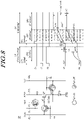
- FIGS. 5 to 9 specifically illustrate a driving method of the subpixel SP shown in FIG. 4 .
- FIGS. 5 to 9 exemplary illustrate a driving method of the subpixel SP in a case that the loss compensation voltage Vc is ⁇ Vth X (1 - B_Remain) ⁇ .
- a compensation period CP for internal compensation before a display period DP there may exist a compensation period CP for internal compensation before a display period DP.
- a first transistor T1 may be turned off, a second transistor T2 may be turned on, and a third transistor T3 may be turned on.
- an initialization voltage Vinit may be applied to a first node N1.
- a reference voltage Vref may be applied to a second node N2.
- the second transistor T2 may be turned off in a sensing period CP2 of the compensation period CP.
- the third transistor T3 may maintain a turn-on state.
- the voltage of the second node N2 may increase.
- the difference between the voltage of the first node N1 and the voltage of the second node N2 may correspond to the threshold voltage Vth of the driving transistor DRT, or may correspond to the changed threshold voltage (Vth + ⁇ Vth) of the driving transistor DRT.
- a change value ⁇ Vth in the threshold voltage Vth of the driving transistor DRT may be compensated for by the internal compensation method.
- the first transistor T1 may be turned on.
- the second transistor T2 and the third transistor T3 may maintain a turn-off state during the display period DP.
- a voltage supplied through the data line DL may be applied to the first node N1.
- the voltage supplied through the data line DL may be a voltage in which a loss compensation voltage Vc for compensating for a loss of a change value ⁇ Vth of the threshold voltage Vth of the driving transistor DRT is added to the data voltage Vdata corresponding to the image data.
- the data voltage output from the data driving circuit 130 to the data line DL may be considered as a voltage obtained by adding a first voltage corresponding to image data and a second voltage for loss compensation.
- (Vdata + Vc) is applied to the first node N1 in a state in which the difference between the voltage of the first node N1 and the voltage of the second node N2 is (Vth + ⁇ Vth)
- the difference between the voltage of the first node N1 and the voltage of the second node N2 may be (Vth + ⁇ Vth + Vdata + Vc).
- the difference Vgs2 between the voltage of the first node N1 and the voltage of the second node N2 may be a voltage obtained by adding Vgs1 before deterioration of the driving transistor DRT to the change value ⁇ Vth of the threshold voltage Vth due to deterioration of the driving transistor DRT and Vc for compensating for a loss of ⁇ Vth during the boosting process.
- the first transistor T1 may be turned off.
- the first node N1 may be in a floating state. Since the first node N1 and the second node N2 are in a floating state, the voltage of the first node N1 and the voltage of the second node N2 may increase.
- the increase of the voltage of the first node N1 and the increase of the voltage of the second node N2 may be stopped.
- a driving current corresponding to a difference between the voltage of the first node N1 and the voltage of the second node N2 may be supplied to the light emitting device ED in a light emission period DP3 of the display period DP.
- the light emitting device ED emits light according to the driving current supplied by the driving transistor DRT, and may display luminance corresponding to image data.
- the difference Vgs2' between the voltage of the first node N1 and the voltage of the second node N2 in the light emission period of the display period DP may be ⁇ Vgs1' + ( ⁇ Vth X B_Remain) + Vc ⁇ .
- Vc may be ⁇ Vth X (1 - B_Remain) ⁇ , which means a value obtained by adding ⁇ Vth to Vgsl' before deterioration of the driving transistor DRT.
- the loss of Vgs1 is maintained the same as before the deterioration of the driving transistor DRT, so that the loss of ⁇ Vth can be compensated to increase the accuracy of compensation of ⁇ Vth by internal compensation.
- the embodiments of the present disclosure there may perform in real time the compensation due to the deterioration of the driving transistor DRT disposed in the subpixel through internal compensation.
- a loss compensation voltage Vc for compensating for the loss of the compensation value during the boosting period to the subpixel SP, it is possible to accurately compensate the deterioration of the driving transistor DRT.
- the loss compensation value Vc may be applied to the first node N1 that a loss by a parasitic capacitance is not occurred in the boosting process, and may be a voltage corresponding to a loss value of ⁇ Vth in the boosting process.
- the loss compensation value Vc may be calculated by dividing the voltage corresponding to the loss value of ⁇ Vth by a value which is greater or equal to the boosting remain ratio and smaller than 1.
- FIGS. 10 and 11 illustrate examples of a method of obtaining a change value ⁇ Vth of a threshold voltage Vth of a driving transistor DRT included in a subpixel SP when driving a subpixel SP according to the driving method of the subpixel shown in FIG. 4 .
- a display device 100 may detect a change value ⁇ Vth of a threshold voltage Vth of the driving transistor DRT by, for example, a method of detecting a change value ⁇ Vth of a characteristic value (e.g. the threshold voltage Vth) of the driving transistor DRT according to an external compensation method.
- the display device 100 may detect the change value ⁇ Vth of the threshold voltage Vth of the driving transistor DRT during the detection period SP.
- the change value ⁇ Vth of the threshold voltage Vth of the driving transistor DRT may be detected by a data driving circuit 130 included in the display device 100.
- the change value ⁇ Vth of the threshold voltage Vth of the driving transistor DRT may be detected by a configuration separately disposed from the data driving circuit 130.
- the detection period SP may be a period other than the frame period during which display driving is performed.
- the detection period SP may be a specific period after driving of the display device 100 is started.
- the detection period SP may be a predetermined period after the driving of the display device 100 is terminated.
- the detection period SP may be at least a partial period of a blank period included in the frame period.
- the detection period (external sensing period) may be a period other than the frame period before or after driving the display.
- the detection period (external sensing period) may be a period included in the frame period.
- the detection period SP may be referred to as an external sensing period.
- the data driving circuit 130 may include a sensing unit 131 and a data voltage output unit 132.
- the detection period SP may include a first detection period SP1 corresponding to an initialization period, a second detection period SP2 corresponding to a sensing period, and a third detection period SP3 corresponding to a sampling period.
- a first transistor T1 may be turned on and a second transistor T2 may be turned on.
- a third transistor T3 may maintain a turn-off state.
- a first switch SW1 electrically connected to a reference voltage line RVL may be turned on, and a second switch SW2 may be turned off.
- a sensing data voltage Vsen output by the data voltage output unit 132 may be applied to the first node N1.
- a reference voltage Vref may be applied to the second node N2.
- the first switch SW1 may be turned off during the sensing period of the detection period SP.
- a voltage of the second node N2 may increase during the sensing period of the detection period SP.
- the voltage of the second node N2 may become a saturation state.
- the second switch SW2 electrically connected between the reference voltage line RVL and an analog-to-digital converter ADC may be turned on.
- the voltage of the second node N2 may be sampled.
- the change value ⁇ Vth of the threshold voltage Vth of the driving transistor DRT may be detected.
- a loss compensation voltage Vc may be calculated using the detected ⁇ Vth.
- the data voltage output unit 132 of the data driving circuit 130 may output a voltage to which the loss compensation voltage Vc is reflected, thereby accurately compensating the ⁇ Vth by the internal compensation.
- the loss compensation voltage Vc may be calculated using the change value ⁇ Vth of the threshold voltage set according to the accumulated stress of the driving transistor DRT, without using the detection method according to the external compensation method.
- the display device 100 may include a look-up table in which a stress value Vstr of the driving transistor DRT and a change value ⁇ Vth corresponding to the stress value Vstr are set.
- Such a look-up table may be stored in a memory located inside or outside the controller 140.
- the stress value Vstr of the driving transistor DRT may be, for example, a value calculated by accumulating the data voltage Vdata supplied to a gate node of the driving transistor DRT as the display device 100 is driven.
- the stress value Vstr may increase.
- the change value ⁇ Vth of the threshold voltage of the driving transistor DRT corresponding to the increased stress value Vstr may be identified through the look-up table.
- a change value corresponding to a first stress value Vstr1 may be ⁇ Vth1
- a change value corresponding to a second stress value Vstr2 may be ⁇ Vth2.
- the loss compensation voltage Vc can be calculated using the identified ⁇ Vth.
- the ⁇ Vth predicted according to the driving of the driving transistor DRT may be used without performing a separate driving for detecting the change value ⁇ Vth of the threshold voltage of the driving transistor DRT, thereby easily calculating the loss compensation voltage Vc for improving the accuracy of internal compensation.
- the change in the characteristic value of the driving transistor DRT disposed in the subpixel SP may be compensated by using the internal compensation method, so that the deterioration of the driving transistor DRT may be easily compensated for in the driving process of the subpixel SP.
- the loss compensation voltage Vc calculated based on a change value of a characteristic value of the driving transistor DRT may be added to the voltage supplied to the subpixel SP. Accordingly, it is possible to prevent the change value ⁇ Vth of the threshold voltage of the driving transistor DRT reflected by the internal compensation from being lost in a boosting period and to improve the accuracy of the internal compensation.
Abstract
Embodiments of the present disclosure relate to a data driving circuit and a display device. In compensating for the change value of the characteristic value of the driving transistor disposed in the subpixel by an internal compensation method, by supplying a voltage including a loss compensation voltage calculated based on the change value of the characteristic value of the driving transistor to the subpixel, it is possible to prevent the compensation value reflected by the internal compensation from being lost in a boosting period after an internal compensation period and to improve the accuracy of the internal compensation. The data driving circuit comprises a sensing unit configured to detect a change value of a threshold voltage of a driving transistor included in at least one of a plurality of subpixels in an external sensing period; and a data voltage output unit configured to supply, in a display period, a data voltage obtained by adding a first voltage corresponding to a luminance of the subpixel and a second voltage smaller than the change value of the threshold voltage of the driving transistor to at least one subpixel of the plurality of subpixels.
Description
- This application claims priority from
Korean Patent Application No. 10-2020-0183849, filed on December 24, 2020 Korean Patent Application No. 10-2021-0135212, filed on October 12, 2021 - The present disclosure relates to a data driving circuit and a display device.
- The growth of the information society leads to increased demand for display devices to display images and use of various types of display devices, such as liquid crystal display devices, organic light emitting display devices, etc.
- Among such display devices, the organic light emitting display device utilizes an organic light emitting diode emitting light by itself, so that there may have advantages in the rapid response speed, excellent contrast ratio and high color reproduction.
- The organic light emitting display device may include, for example, an organic light emitting diode disposed in each subpixel, and a driving transistor for supplying a driving current to the organic light emitting diode.
- As the driving time of the organic light emitting display device increases, circuit elements such as organic light emitting diodes and driving transistors disposed in subpixels may deteriorate. Further, a characteristic value of the driving transistor may change due to deterioration of the driving transistor.
- As the characteristic values of the driving transistors change, there may occur deviations in characteristic values between the driving transistors disposed in the subpixels, so that the driving current supplied to the organic light emitting diode by the driving transistor may not be accurately controlled.
- Accordingly, there is a need for a method for preventing image quality abnormality of the organic light emitting display device due to deterioration of the driving transistor.
- Embodiments of the present disclosure may provide a manner capable of compensating the change in characteristic value due to deterioration of a driving transistor supplying a driving current to a light emitting device disposed in a subpixel by a circuit structure and driving method of the subpixel.
- Embodiments of the present disclosure may provide a manner capable of improving an accuracy of compensation in compensating for changes in characteristic values due to deterioration of the driving transistor by the circuit structure and driving method of the subpixel.
- In one aspect, embodiments of the present disclosure may provide a display device including a display panel on which a plurality of subpixels are disposed, and a data driving circuit supplying a data voltage to the plurality of subpixels. Each of the plurality of subpixels may include a light emitting device, a driving transistor for driving the light emitting device, and a storage capacitor electrically connected between a first node and a second node of the driving transistor. The data driving circuit may detect, in an external sensing period, a change value of a threshold voltage of the driving transistor included in at least one of the plurality of subpixels. The data driving circuit may supply, in a display period, the data voltage obtained by adding a first voltage corresponding to a luminance of the light emitting device and a second voltage smaller than the change value of the threshold voltage of the driving transistor to at least one subpixel of the plurality of subpixels. In particular a display device may comprise a display panel on which a plurality of subpixels, a plurality of gate lines and a plurality of data lines are disposed, wherein each subpixel is positioned in a region, where one of the plurality of gate lines intersects with one of the plurality of data lines; and a data driving circuit configured to supply a data voltage to each of the data lines, wherein each of the plurality of subpixels emit light having a brightness according to the supplied data voltage, wherein each of the plurality of subpixels comprises a light emitting device; a subpixel circuit comprising: a driving transistor configured to drive the light emitting device and a storage capacitor electrically connected between a first node and a second node of the driving transistor, wherein the data driving circuit is configured to detect, in an external sensing period, a change value of a threshold voltage of the driving transistor included in at least one of the plurality of subpixels, and to supply, in a display period, the data voltage obtained by adding a first voltage corresponding to a luminance of the light emitting device and a second voltage smaller than the change value of the threshold voltage of the driving transistor to at least one subpixel of the plurality of subpixels.
- The second voltage may be a value obtained by multiplying the change value of the threshold voltage of the driving transistor by a boosting loss ratio.
- The boosting loss ratio may be a value obtained by subtracting a boosting remain ratio from 1.
- The boosting remain ratio may be a ratio of a change value of a voltage of the second node of the driving transistor in a light emission period of the display period with respect to a change value of a voltage of the second node configured based on a difference between a voltage of the first node and a voltage of the second node of the driving transistor in a data writing period of the display period.
- The boosting remain ratio may be a ratio of a capacitance by the storage capacitor to a sum of a parasitic capacitance formed by the first node of the driving transistor and the capacitance by the storage capacitor.
- In another aspect, embodiments of the present disclosure may provide a display device including a display panel on which a plurality of subpixels including a light emitting device and a driving transistor for driving the light emitting device are disposed, and a data driving circuit for supplying a data voltage to the plurality of subpixels. The data driving circuit may supply, in a display period, the data voltage obtained by adding a first voltage corresponding to a luminance of the light emitting device and a second voltage smaller than a change value of a threshold voltage of the driving transistor to at least one subpixel of the plurality of subpixels.
- In another aspect, embodiments of the present disclosure may provide a data driving circuit including a sensing unit configured to detect a change value of a threshold voltage of a driving transistor included in at least one of a plurality of subpixels in an external sensing period, and a data voltage output unit configured to supply, in a display period, a data voltage obtained by adding a first voltage corresponding to a luminance of the subpixel and a second voltage smaller than the change value of a threshold voltage of the driving transistor to at least one subpixel of the plurality of subpixels.
- According to embodiments of the present disclosure, a voltage difference between a gate node and a source node of the driving transistor corresponds to the changed threshold voltage of the driving transistor, so that it is possible to compensate a change in the characteristic value of a driving transistor during the driving process of the subpixel.
- According to embodiments of the present disclosure, there may be supplied with a data voltage including a voltage capable of compensating for a loss of a change value of a threshold voltage of the driving transistor in a data writing period of the display period, so that it is possible to prevent loss of the change value of the threshold voltage of the driving transistor during a boosting period.
- According to embodiments of the present disclosure, in compensating for the change value of the characteristic value of the driving transistor disposed in the subpixel by an internal compensation method, by supplying a voltage including a loss compensation voltage calculated based on the change value of the characteristic value of the driving transistor to the subpixel, it is possible to prevent the compensation value reflected by the internal compensation from being lost in a boosting period after an internal compensation period and to improve the accuracy of the internal compensation.
-
-
FIG. 1 schematically illustrates a configuration of a display device according to embodiments of the present disclosure. -
FIG. 2 illustrates an example of a circuit structure of a subpixel included in a display device according to embodiments of the present disclosure. -
FIG. 3 illustrates an example of a driving method of a subpixel included in a display device according to embodiments of the present disclosure. -
FIG. 4 illustrates another example of a driving method of a subpixel included in a display device according to embodiments of the present disclosure. -
FIGS. 5 to 9 specifically illustrate a driving method of the subpixel shown inFIG. 4 . -
FIGS. 10 and11 illustrate examples of a method of obtaining a change value of a threshold voltage of a driving transistor included in a subpixel when driving a subpixel according to the driving method of the subpixel shown inFIG. 4 . - In the following description of examples or embodiments of the present disclosure, reference will be made to the accompanying drawings in which it is shown by way of illustration specific examples or embodiments that can be implemented, and in which the same reference numerals and signs can be used to designate the same or like components even when they are shown in different accompanying drawings from one another. Further, in the following description of examples or embodiments of the present disclosure, detailed descriptions of well-known functions and components incorporated herein will be omitted when it is determined that the description may make the subject matter in some embodiments of the present disclosure rather unclear. The terms such as "including", "having", "containing", and "constituting" used herein are generally intended to allow other components to be added unless the terms are used with the term "only". As used herein, singular forms are intended to include plural forms unless the context clearly indicates otherwise.
- Terms, such as "first", "second", "A", "B", "(A)", or "(B)" may be used herein to describe elements of the present disclosure. Each of these terms is not used to define essence, order, sequence, or number of elements etc., but is used merely to distinguish the corresponding element from other elements.
- When it is mentioned that a first element "is connected or coupled to", "overlaps" etc. a second element, it should be interpreted that, not only can the first element "be directly connected or coupled to" or "directly contact or overlap" the second element, but a third element can also be "interposed" between the first and second elements, or the first and second elements can "be connected or coupled to", "overlap", etc. each other via a fourth element. Here, the second element may be included in at least one of two or more elements that "are connected or coupled to", "contact or overlap", etc. each other.
- When time relative terms, such as "after," "subsequent to," "next," "before," and the like, are used to describe processes or operations of elements or configurations, or flows or steps in operating, processing, manufacturing methods, these terms may be used to describe non-consecutive or non-sequential processes or operations unless the term "directly" or "immediately" is used together.
- In addition, when any dimensions, relative sizes etc. are mentioned, it should be considered that numerical values for an elements or features, or corresponding information (e.g., level, range, etc.) include a tolerance or error range that may be caused by various factors (e.g., process factors, internal or external impact, noise, etc.) even when a relevant description is not specified. Further, the term "may" fully encompasses all the meanings of the term "can".
-
FIG. 1 schematically illustrates a configuration included in adisplay device 100 according to embodiments of the present disclosure. - Referring to
FIG. 1 , thedisplay device 100 may include adisplay panel 110, agate driving circuit 120 and adata driving circuit 130 for driving thedisplay panel 110, acontroller 140, or the like. - In the
display panel 110, a plurality of subpixels SP is disposed. Thedisplay panel 110 may include an active area AA in which the plurality of subpixels SP are disposed, and a non-active area NA positioned outside the active area AA. - A plurality of gate lines GL and a plurality of data lines DL may be disposed on the
display panel 110. The subpixel SP may be positioned in a region where the gate line GL and the data line DL intersect. - The
gate driving circuit 120 is controlled by thecontroller 140. Thegate driving circuit 120 can sequentially output scan signals to the plurality of gate lines GL arranged on thedisplay panel 110, thereby controlling the driving timing of the plurality of subpixels SP. - The
gate driving circuit 120 may include one or more gate driver integrated circuits GDIC. Thegate driving circuit 120 may be located only at one side of thedisplay panel 110, or can be located at both sides thereof according to a driving method. - Each gate driver integrated circuit GDIC may be connected to a bonding pad of the
display panel 110 by a tape automated bonding (TAB) method or a chip-on-glass (COG) method. Alternatively, each gate driver integrated circuit GDIC may be implemented as a gate-in-panel (GIP) type and disposed directly on thedisplay panel 110. Alternatively, each gate driver integrated circuit GDIC may be integrated and disposed on thedisplay panel 110 in some cases. Alternatively, each gate driver integrated circuit GDIC may be implemented in a chip-on-film (COF) method mounted on a film connected to thedisplay panel 110. - The
data driving circuit 130 may receive data signal DATA from thecontroller 140 and converts the data signal into an analog data voltage Vdata. Thedata driving circuit 130 outputs (supplies) the data voltage Vdata (independently) to each data line DL of the plurality of data lines DL, preferably according to the timing at which the scan signal is applied through the respective gate line GL of the plurality of gate lines GL so that each of the plurality of subpixels SP emits light having brightness according to the supplied data voltage Vdata, which in turn corresponds to the received data signal DATA. - The
data driving circuit 130 may include one or more source driver integrated circuits SDIC. - Each source driver integrated circuit SDIC may include a shift register, a latch circuit, a digital-to-analog converter, an output buffer, and the like.
- Each source driver integrated circuit SDIC may be connected to a bonding pad of the
display panel 110 by a tape automated bonding (TAB) method or a chip-on-glass (COG) method. Alternatively, each source driver integrated circuit SDIC may be disposed directly on thedisplay panel 110. Alternatively, each source driver integrated circuit SDIC may be integrated and disposed on thedisplay panel 110 in some cases. Alternatively, each source driver integrated circuit SDIC may be implemented in a chip-on-film (COF) manner. In this case, each source driver integrated circuit SDIC may be mounted on a film connected to thedisplay panel 110, and may be electrically connected to thedisplay panel 110 through lines on the film. - The
controller 140 may supply various control signals to thegate driving circuit 120 and thedata driving circuit 130, and control the operation of thegate driving circuit 120 and thedata driving circuit 130. - The
controller 140 may be mounted on a printed circuit board or a flexible printed circuit. Thecontroller 140 may be electrically connected to thegate driving circuit 120 and thedata driving circuit 130 through a printed circuit board or a flexible printed circuit. - The
controller 140 may control thegate driving circuit 120 to output a scan signal according to timing implemented in each frame. Thecontroller 140 may convert externally received image data to match a signal format used by thedata driving circuit 130, and output the converted data signal to thedata driving circuit 130. - The
controller 140 may receive various timing signals including a vertical synchronization signal VSYNC, a horizontal synchronization signal HSYNC, an input data enable signal DE, a clock signal CLK from the outside (e.g., host system). - The
controller 140 may generate various control signals by using various timing signals received from the outside, and may output the control signals to thegate driving circuit 120 and thedata driving circuit 130. - For example, in order to control the
gate driving circuit 120, thecontroller 140 may output various gate control signals GCS including a gate start pulse GSP, a gate shift clock GSC, and a gate output enable signal GOE. - The gate start pulse GSP controls operation start timing of one or more gate driver integrated circuits GDIC constituting the
gate driving circuit 120. The gate shift clock GSC, which is a clock signal commonly input to one or more gate driver integrated circuits GDIC, controls the shift timing of a scan signal. The gate output enable signal GOE specifies timing information on one or more gate driver integrated circuits GDIC. - In addition, in order to control the
data driving circuit 130, thecontroller 140 may output various data control signals DCS including a source start pulse SSP, a source sampling clock SSC, a source output enable signal SOE, or the like. - The source start pulse SSP controls a data sampling start timing of one or more source driver integrated circuits SDIC constituting the
data driving circuit 130. The source sampling clock SSC is a clock signal for controlling the timing of sampling data in the respective source driver integrated circuits SDIC. The source output enable signal SOE controls the output timing of thedata driving circuit 130. - The
display device 100 may further include a power management integrated circuit for supplying various voltages or currents to thedisplay panel 110, thegate driving circuit 120, thedata driving circuit 130, and the like or controlling various voltages or currents to be supplied thereto. - Each subpixel SP may be a region defined by the intersection of the gate line GL and the data line DL, in which at least one circuit element including a light emitting device may be disposed.
- For example, in the case that the
display device 100 is an organic light emitting display device, an organic light emitting diode OLED and various circuit elements may be disposed in the plurality of subpixels SP. Thedisplay device 100 controls the electrical current supplied to the organic light emitting diode OLED disposed in the subpixel SP by driving several circuit elements, so that each subpixel SP may be controlled to display brightness corresponding to image data. To control the electrical current, thedata driving circuit 130 may output (supply) the data voltage Vdata (independently) to each data line DL of the plurality of data lines DL, preferably according to the timing at which the scan signal is applied through the respective gate line GL of the plurality of gate lines GL, to the several circuit elements in a particular subpixel SP. In conclusion, each of the plurality of subpixels SP emits light having brightness according to the supplied data voltage Vdata, which in turn corresponds to the received data signal DATA. -
FIG. 2 illustrates an example of a circuit structure of the subpixel SP included in thedisplay device 100 according to embodiments of the present disclosure. The term "circuit structure" can be used interchangably with the term "subpixel circuit". Each subpixel circuit may comprise the several circuit elements. The term "several circuit elements" refers to a minimum of two different circuit elements of the subpixel circuit, namely one driving transistor DRT and one capacitor Cstg. - Referring to
FIG. 2 , each of the plurality of subpixels SP disposed on thedisplay panel 110 may include a light emitting device ED and a driving transistor DRT for driving the light emitting device ED. - The subpixel circuit may include further circuit elements, such as one or more transistors in addition to the driving transistor DRT. The subpixel circuit may include further circuit elements, such as more than one capacitor. The number of circuit elements in the subpixel circuit is dependent on the actual application of the display device. The following examplary embodiments of the structure of a subpixel circuit are not complete. Besides the concrete examples provided hereinafter, other structures such as 3TC1, 5TC1, 6TC1, 7TC1, 8TC1, 3TC2, 4TC2, 5TC2, 6TC2, 7TC2 or 8TC2 are known in the field and may be used instead for the inventive concept.
-
FIG. 2 illustrates an example in which three transistors T1, T2 and T3 are disposed in the subpixel SP in addition to the driving transistor DRT, and one storage capacitor Cstg is disposed.FIG. 2 illustrates an example of a 4T1C structure, however, embodiments of the present disclosure are not limited thereto. - The driving transistor DRT may be electrically connected between a driving voltage line DVL and a light emitting device ED. A first driving voltage EVDD may be supplied through the driving voltage line DVL, and the first driving voltage EVDD may be a high potential driving voltage.
- The driving transistor DRT may control the driving current supplied to the light emitting device ED.
- One electrode of the light emitting device ED may be electrically connected to the driving transistor DRT. The other electrode of the light emitting device ED may be electrically connected to a second driving voltage EVSS. The second driving voltage EVSS may be a low potential driving voltage.
- The light emitting device ED may emit light according to the driving current supplied from the driving transistor DRT, and may express the luminance corresponding to image data.
- The first transistor T1 may be electrically connected between the data line DL and a first node N1. The first node N1 may be a gate node of the driving transistor DRT.
- The first transistor T1 may be controlled by a scan signal supplied through the gate line GL.
- The first transistor T1 may be controlled so that a data voltage Vdata supplied through the data line DL is applied to the first node N1 which is the gate node of the driving transistor DRT.
- The second transistor T2 may be electrically connected between the reference voltage line RVL and a second node N2. The second node N2 may be a source node or a drain node of the driving transistor DRT. A third node N3 to which the driving transistor DRT is electrically connected to the driving voltage line DVL may be a drain node or a source node.
- The second transistor T2 may be controlled by a scan signal supplied through the gate line GL.
- The second transistor T2 may be controlled so that a reference voltage Vref supplied through the reference voltage line RVL is applied to the second node N2.
- The third transistor T3 may be electrically connected between an initialization voltage line IVL and the first node N1.
- The third transistor T3 may be controlled by a scan signal supplied through the gate line GL.
- The third transistor T3 may control the application of an initialization voltage Vinit to the first node N1 which is the gate node of the driving transistor DRT.
- The storage capacitor Cstg may be electrically connected between the first node N1 and the second node N2. The storage capacitor Cstg may maintain the data voltage Vdata for one frame period.
- The driving transistor DRT or the light emitting device ED disposed in the subpixel SP may be deteriorated as the driving time of the
display device 100 increases. The deterioration of the driving transistor DRT may cause a change in a characteristic value such as a threshold voltage or mobility of the driving transistor DRT. - The
display device 100 according to embodiments of the present disclosure may provide a method for compensating for deterioration of the driving transistor DRT disposed in the subpixel SP. - As an example, the characteristic value of the driving transistor DRT disposed in the subpixel SP may be detected during a preset period.
- The data voltage Vdata may be supplied by adding a compensation value calculated based on the detected characteristic value, so that it is possible to compensate a change in the characteristic value of the driving transistor DRT. This compensation method may be referred to as an external compensation method.
- Alternatively, the compensation for the characteristic value of the driving transistor DRT may be preformed during the driving process of the subpixel SP. Since the data voltage Vdata is supplied after compensation is performed, the display driving may be performed without being affected by a change in the characteristic value of the driving transistor DRT. This compensation method may be referred to as an internal compensation method.
- The circuit structure of the subpixel SP shown in
FIG. 2 is a structure in which both the above-described external compensation and internal compensation can be performed. The change in the characteristic value of the driving transistor DRT may be compensated by the external compensation method or the internal compensation method according to circumstances. - In the case that the compensation for a change in the characteristic value of the driving transistor DRT is performed by the internal compensation, the change in the characteristic value of the driving transistor DRT may be compensated for simultaneously with driving the display without performing driving for detecting the characteristic value of the driving transistor DRT.
-
FIG. 3 illustrates an example of a driving method of a subpixel included in adisplay device 100 according to embodiments of the present disclosure. -
FIG. 3 illustrates an example of a internal compensation method for compensating for a change in the characteristic value of the driving transistor DRT disposed in the subpixel SP during the driving process of the subpixel SP. - For example, one frame period for driving the subpixel SP may include a compensation period CP and a display period DP. The frame period is a time period. The frame period is also referred to the frame rate (expressed in frames per second or FPS) which is the frequency (rate) at which images (frames) are displayed on the
display device 100. The frame period can be 1/(the frame rate). The frame period can include an active period and a blank period. The active period can be a time period that the data voltage Vdata is supplied to the subpixel SP. And the blank period can be a time period between the two adjacent active periods. - The compensation period CP may include a first compensation period CP1 corresponding to an initialization period and a second compensation period CP2 corresponding to a sensing period. Here, the sensing period is a sensing period for internal compensation and may be referred to as an internal sensing period.
- The display period DP may include a first display period DP1 corresponding to a data writing period, a second display period DP2 corresponding to a boosting period, and a third display period DP3 corresponding to a light emission period.
- In the initialization period of the compensation period CP, the first transistor T1 may be in a turn-off state. In the initialization period of the compensation period CP, the second transistor T2 may be turned on and the third transistor T3 may be turned on.
- Since the third transistor T3 is turned on, an initialization voltage Vinit may be applied to the first node N1. Since the second transistor T2 is turned on, a reference voltage Vref may be applied to the second node N2.
- The difference between the initialization voltage Vinit and the reference voltage Vref may be, for example, greater than the threshold voltage Vth of the driving transistor DRT.
- In the sensing period of the compensation period CP, the second transistor T2 may be turned off, and the third transistor T3 may maintain a turn-on state.
- Since the second transistor T2 is turned off, the second node N2 may be in a floating state.
- Since the second node N2 is in the floating state and the initialization voltage Vinit is applied to the first node N1, a voltage of the second node N2 forming a capacitance with the first node N1 may increase. So, the voltage of the second node N2 increases. The first node N1 and the second node N2 form a capacitance.
- If a certain time elapses, the voltage of the second node N2 may be in a saturation state.
- In the saturation state, a difference between the voltage of the first node N1 and the voltage of the second node N2 may correspond to the threshold voltage Vth of the driving transistor DRT. In addition, if the driving transistor DRT is deteriorated, the difference between the voltage of the first node N1 and the voltage of the second node N2 in the saturation state may correspond to (Vth + ΔVth) which is the changed threshold voltage of the driving transistor DRT.
- By driving in the compensation period CP, a voltage difference corresponding to the changed threshold voltage Vth of the driving transistor DRT may be formed between the first node N1 as the gate node of the driving transistor DRT and the second node N2 as the source node of the driving transistor DRT.
- Accordingly, it is possible to compensate for the change value ΔVth of the threshold voltage Vth of the driving transistor DRT. In an embodiment, the change value ΔVth of the threshold voltage Vth of the driving transistor DRT included in a first subpixel among the plurality of subpixels SP may be 0, and the change value ΔVth of the threshold voltage Vth of the driving transistor DRT included in a second subpixel may be not zero. Further, in a light emission period of the display period DP, a voltage of the second node N2 of the driving transistor DRT included in the first subpixel may be the same as a voltage of the second node N2 of the driving transistor DRT included in the second subpixel.
- In the display period DP after the compensation period CP, the first transistor T1 may be turned on during the data writing period DP1.
- Since the first transistor T1 is turned on, the data voltage Vdata supplied through the data line DL may be applied to the first node N1.
- The data voltage Vdata may be a voltage corresponding to the luminance of the light emitting device ED disposed in the subpixel SP. That is, it may be a voltage for expressing a grayscale according to image data.
- The first transistor T1 may be turned off during the boosting period DP2 of the display period DP.
- Since the second transistor T2 is also turned off during the boosting period DP2 of the display period DP, both the first node N1 and the second node N2 may be in a floating state.
- Since both, the first node N1 and the second node N2 are in the floating state, the voltage of the first node N1 and the voltage of the second node N2 may increase. A degree that the voltage of the second node N2 increase may be ΔVs, and the degree may be configured based on the voltage applied to the first node N1 and the voltage applied to the second node N2.
- If the voltage of the second node N2 increases to match an operating point of the light emitting device ED, a driving current corresponding to the difference between the voltage of the gate node of the driving transistor DRT and the voltage of the source node of the driving transistor DRT may be supplied to the light emitting device ED.
- During the light emission period DP3 of the display period DP, the voltage of the first node N1 and the voltage of the second node N2 are constantly maintained, and the light emitting device ED may display a luminance corresponding to the data voltage Vdata.
- As described above, according to the embodiments of the present disclosure, the change in the characteristic value of the driving transistor DRT disposed in the subpixel SP may be compensated for in real time by the driving of the internal compensation method, and the display device may be driven.
- Meanwhile, in the above-described example, information about the characteristic value of the driving transistor DRT may be applied to the second node N2 which is the source node of the driving transistor DRT.
- Accordingly, in the boosting period DP2 of the display period DP, information on the characteristic value of the driving transistor DRT stored in the second node N2 may be transmitted to the first node N1 serving as the gate node.
- In this case, the first node N1 forms a capacitance by the second node N2 and the storage capacitor Cstg, but may also form a parasitic capacitance with other signal lines in the subpixel SP.
- For example, the first node N1 may form a parasitic capacitance with a voltage line such as the gate line GL or the driving voltage line DVL in the subpixel SP. In addition, there may occur a loss in a process in which information on the characteristic value of the driving transistor DRT stored in the second node N2 is transmitted to the first node N1 due to the parasitic capacitance.
- Referring to
FIG. 3 , in the case that the threshold voltage of the driving transistor DRT is Vth since deterioration of the driving transistor DRT does not proceed, the difference Vgs1 between the voltage of the first node N1 and the voltage of the second node N2 during the data writing period of the display period DP may be (Vdata + Vth). - When a boosting remain ratio excluding the loss due to parasitic capacitance in the boosting process is refer as B_Remain, the boosting remain ratio B_Remain may be a value less than 1 (e.g., 0.5, 0.6, etc.). A boosting loss ratio may be a value obtained by subtrating the boosting remain ratio from 1.
- The difference between the voltage of the first node N1 and the voltage of the second node N2 during the light emission period of the display period DP may be Vgsl'.
- Vgsl' may be different from Vgs1 which is a difference between the voltage of the first node N1 and the voltage of the second node N2 in the data writing period DP1. For example, Vgsl' may be smaller than Vgs1. Vgsl' may be a value obtained by subtracting a loss value of ΔVs from Vgs1. In other words, Vgsl' may be a value obtained by substracting the lost value of ΔVs configured based on Vgs1 in a boosting process from Vgs1.
- Alternatively, in some cases, Vgsl' may be (Vgsl X B Remain). Vgs1 may be lost to be remained as the boosting remain ratio in the boosting process. Alternatively, in some cases, Vgsl' may be (Vgsl X B_Remain'). B Remain' may be greater than B_Remain. Since a loss is occurred on the second node N2 in the boosting process, a loss value of Vgs1 may be smaller than a loss value of the voltage of the second node N2.
- In the case that the deterioration of the driving transistor DRT progresses and the change value of the threshold voltage Vth of the driving transistor DRT becomes ΔVth, the difference Vgs2 between the voltage of the first node N1 and the voltage of the second node N2 in the data writing period DP1 of the display period DP may be (Vgsl + ΔVth).
- During the light emission period DP3 of the display period DP, Vgs1 may become Vgs1'. ΔVth may become (ΔVth X B_Remain) in the light emission period DP3 by a loss in the boosting process. Vgs2' may become {Vgs1' + (ΔVth X B_Remain)}.
- Such as above-mentioned, since a loss of ΔVth compensated for in the compensation period CP occurs, the position of the operating point of the light emitting device ED may be changed during the light emission period due to inaccurate compensation of ΔVth.
- Accordingly, as the light emission period DP3 of the display period DP shown in
FIG. 3 , there may exist a difference ΔD between the voltage of the second node N2 before the deterioration of the driving transistor DRT and the voltage of the second node N2 after the deterioration of the driving transistor DRT. As a result, there may generate a non-uniform driving between the subpixels SP due to this difference. - Embodiments of the present disclosure may provide a method capable of preventing loss of compensation values during the boosting period DP2 and improving the accuracy of compensation in the process of compensating for changes in the characteristic values of the driving transistors DRT using the internal compensation method.
-
FIG. 4 illustrates another example of a driving method of a subpixel included in adisplay device 100 according to embodiments of the present disclosure. - Referring to
FIG. 4 , one frame period in which the subpixel SP is driven may include a compensation period CP and a display period DP. - In an initialization period CP1 of the compensation period CP, an initialization voltage Vinit may be applied to a first node N1 and a reference voltage Vref may be applied to a second node N2. In a sensing period CP2 of the compensation period CP, the second node N2 may be in a floating state, and the voltage of the second node N2 may increase.
- The difference between the voltage of the first node N1 and the voltage of the second node N2 through the compensation period CP may correspond to (Vth + ΔVth), which is the changed threshold voltage of the driving transistor DRT. In addition, the example shown in
FIG. 4 illustrates an example in which ΔVth is positively shifted, but in some cases, ΔVth may be negatively shifted. - The voltage applied to the first node N1 in a data writing period of the display period DP may be the sum of the data voltage Vdata and the loss compensation voltage Vc.
- Here, the data voltage Vdata may be a voltage corresponding to the luminance displayed by the light emitting device ED disposed in the subpixel SP. In addition, the loss compensation voltage Vc may be a voltage for compensating for loss in a boosting process of the change value ΔVth of the threshold voltage Vth of the driving transistor DRT compensated for in the compensation period CP.
- As an example, the loss compensation voltage Vc may be a value obtained by multiplying the change value ΔVth of the threshold voltage Vth of the driving transistor DRT by a boosting loss ratio.
- The boosting loss ratio may be referred as B_Loss, and the boosting loss ratio B_Loss may be expressed as (1 - B_Remain). That is, the sum of the boosting loss ratio and the boosting remain ratio may be 1.
- Accordingly, the loss compensation voltage Vc may be expressed as (ΔVth ∗ (1 - B_Remain)).
- The boosting remain ratio may be a ratio of the voltage excluding the voltage lost by the parasitic capacitance in the boosting process.
- The boosting remain ratio may be, for example, a ratio of a change value of a voltage of the second node N2 in a light emission period of the display period DP with respect to the change value ΔVs of the voltage of the second node N2 configured based on a difference between a voltage of the first node N1 and a voltage of the second node N2 in a data writing period DP1 of the display period DP . Alternatively, in some cases, the boosting remain ratio may be, in a state in which the change value ΔVth of the threshold voltage of the driving transistor DRT is 0, a ratio of a difference between a voltage of the first node N1 and a voltage of the second node N2 in a light emission period of the display period DP with respect to a difference between a voltage of the first node N1 and a voltage of the second node N2 in the data writing period of the display period DP.
- Alternatively, the boosting remain ratio may be a ratio of a capacitance by the storage capacitor Cstg to a sum of a parasitic capacitance Cpara formed by the first node N1 and the capacitance by the storage capacitor Cstg (i.e., B_Remain = Cstg / (Cpara + Cstg)).
- Since the boosting remain ratio is less than 1, the loss compensation voltage Vc may be smaller than the change value ΔVth of the threshold voltage of the driving transistor DRT.
- The loss compensation voltage Vc set in consideration of the boosting remain ratio may be supplied to the first node N1 in addition to the data voltage Vdata during the data writing period DP1 of the display period DP.
- When the data voltage Vdata is applied to the first node N1 of the driving transistor DRT, there may be added (ΔVth X ( 1 - B_Remain)), which is a value at which the change value ΔVth of the threshold voltage of the driving transistor can be lost in the boosting process, so that it is possible to compensate for the loss of ΔVth in the boosting period and to improve the accuracy of the compensation.
- For example, as the internal compensation is performed in the compensation period CP before the display period DP, the difference between the voltage of the first node N1 and the voltage of the second node N2 may be a voltage corresponding to (Vth + ΔVth) which is a changed threshold voltage Vth of the driving transistor DRT. A compensation for ΔVth which is a changed value of the threshold voltage may be performed.
- The data voltage Vdata and the loss compensation voltage Vc may be applied to the first node N1 in the data writing period DP1 of the display period DP.
- The data voltage Vdata may be a voltage corresponding to a luminance that the light emitting device ED represents. The loss compensation voltage Vc may be a voltage for compensating that ΔVth compensated in the compensation period CP is lost in the boosting process.
- It may mean that the data voltage Vdata which is sum of a first voltage corrpesonding to a luminance the light emitting device ED represents and a second voltage for compensating a loss of ΔVth is applied to the first node N1.
- As ΔVth is applied to the second node N2 in the compensation period CP, ΔVth may be lost in the boosting process. A loss of ΔVth may be compensated by the loss compensation voltage Vc which is applied to the first node N1 with the data voltage Vdata.
- As (Vdata + Vc) is applied to the first node N1 in the data writing period of the display period DP, Vgs2 which is a difference between the voltage of the first node N1 and the voltage of the second node N2 may be (Vgs1 + ΔVth + Vc).
- A loss by a parasitic capacitance formed by the first node N1 may be occurred in the boosting period DP2 of the display period DP. Vgs2 of the data writing period of the display period DP may be changed to Vgs2' in the light emission period of the display period DP. Vgs2' may be expressed as follows.

- As the loss compensation voltage Vc is applied to the first node N1 with the data voltage Vdata, the loss compensation voltage Vc may not be lost unlike the voltage of the second node N2 is lost in the boosting period. The loss compensation voltage Vc may be maintained on the first node N1 in the light emission period after the boosting period of the display period DP. A lost value of ΔVth may be compensated by the loss compensation voltage Vc.
- A changed value ΔVth of the threshold voltage Vth compensated in the compensation period CP before the display period DP may be maintained in the light emission period DP3 of the display period DP. The changed value ΔVth of the threshold voltage Vth according to the degeneration of the driving transistor DRT may be compensated accurately. As the changed value ΔVth of the threshold voltage Vth is compensated accurately, a luminance that the subpixel SP represents may be controlled accurately. It may be prevented that a display quality is dropped.
- Alternatively, the loss compensation voltage Vc may be a value obtained by multiplying the change value ΔVth of the threshold voltage Vth of the driving transistor DRT by the boosting loss ratio. Alternatively, the loss compensation voltage Vc may be a value obtained by dividing a value obtained by multiplying the change value ΔVth of the threshold voltage Vth of the driving transistor DRT by the boosting loss ratio by a value which is greater than the boosting remain ratio and smaller than 1.
- As the loss compensation voltage Vc is applied to the first node N1 in the data writing period DP1 of the dislay period DP, the loss compensation voltage Vc may not be lost when the voltage of the second node N2 increases. But, in some cases, the loss compensation voltage Vc may be lost as smaller ratio than a ratio that the voltage of the second node N2 is lost.
- Alternatively, in some cases, the loss compensation voltage Vc may be lost as same ratio with the ratio that the voltage of the second node N2 is lost.
- For example, in a case that the loss compensation voltage Vc is lost as same ratio with the ratio that the voltage of the second node N2 is lost, the loss compensation voltage Vc may be expressed as (ΔVth ∗ B_Loss / B_Remain) or as (ΔVth ∗ (1 - B_Remain) / B_Remain).
- If the boosting remain ratio is 0.5 or more, ((1 - B_Remain) / B Remain) may be less than 1. Accordingly, the loss compensation voltage Vc may be smaller than the change value ΔVth of the threshold voltage Vth of the driving transistor DRT.
- In some cases, if the boosting remain ratio is less than 0.5, the loss compensation voltage Vc may be greater than the change value ΔVth of the threshold voltage Vth of the driving transistor DRT.
- The loss compensation voltage Vc may be set in consideration of the fact that the loss compensation voltage Vc may be lost during the boosting process, thereby preventing the loss of change value ΔVth of the threshold voltage Vth of the driving transistor DRT during the boosting process and accurately performing the compensation of ΔVth by the internal compensation.
- For example, as the internal compensation is performed in the compensation period CP before the display period DP, the difference between the voltage of the first node N1 and the voltage of the second node N2 may be a voltage corresponding to the changed threshold voltage (Vth + ΔVth) of the driving transistor DRT.
- In a data writing period of the display period DP, a voltage obtained by summing the data voltage Vdata and the loss compensation voltage Vc may be applied to the first node N1.
- The data voltage Vdata may be a voltage corresponding to the luminance of the light emitting device ED, and the loss compensation voltage Vc may be a voltage for compensating for a loss of the compensated ΔVth in the boosting process.
- There may be considered that the data voltage Vdata obtained by adding a first voltage corresponding to the luminance of the light emitting device ED and a second voltage which may be smaller than the change value ΔVth of the threshold voltage of the driving transistor DRT for compensating for the loss of ΔVth (i.e., the loss compensation voltage) is supplied to the first node N1. In an embodiment, in the light emission period of the display period, a value obtained by subtracting the change value of the threshold voltage of the driving transistor DRT from a difference between a voltage of the first node N1 and a voltage of the second node N2 of the driving transistor DRT may be less than the sum of the first voltage and the threshold voltage of the driving transistor DRT.
- Since (Vdata + Vc) is supplied to the first node N1 in the data writing period of the display period DP, the difference Vgs2 between the voltage of the first node N1 and the voltage of the second node N2 may be (Vgsl + ΔVth + Vc).
- Since loss due to the parasitic capacitance formed by the first node N1 occurs during the boosting period of the display period DP, the difference Vgs2' between the voltage of the first node N1 and the voltage of the second node N2 in the light emission period of the display period DP may be (Vgs2 ∗ B_Remain). Further, Vgs2' may be expressed as follows.

- Accordingly, the difference Vgs2' between the voltage of the first node N1 and the voltage of the second node N2 in the light emission period DP3 of the display period DP may be a value obtained by adding ΔVth to (Vgsl ∗ B_Remain) which is Vgs2 before deterioration of the driving transistor DRT, so that accurate compensation of the change value ΔVth of the threshold voltage Vth of the driving transistor DRT can be performed.
- In addition, since accurate compensation for the change value ΔVth of the threshold voltage Vth of the driving transistor DRT is performed, the operating point of the light emitting device ED may be constantly maintained.
- In the light emission period of the display period DP, the voltage of the second node N2 before the deterioration of the driving transistor DRT and the voltage of the second node N2 after the deterioration of the driving transistor DRT may be maintained to be the same (i.e., ΔD' = 0). Accordingly, it is possible to prevent non-uniform driving due to a deviation between subpixels SP having different degrees of deterioration of the driving transistor DRT.
-
FIGS. 5 to 9 specifically illustrate a driving method of the subpixel SP shown inFIG. 4 .FIGS. 5 to 9 exemplary illustrate a driving method of the subpixel SP in a case that the loss compensation voltage Vc is {ΔVth X (1 - B_Remain)}. - Referring to
FIG. 5 , there may exist a compensation period CP for internal compensation before a display period DP. - In an initialization period CP1 of the compensation period CP, a first transistor T1 may be turned off, a second transistor T2 may be turned on, and a third transistor T3 may be turned on..
- As the third transistor T3 is turned on, an initialization voltage Vinit may be applied to a first node N1. As the second transistor T2 is turned on, a reference voltage Vref may be applied to a second node N2.
- Referring to
FIG. 6 , the second transistor T2 may be turned off in a sensing period CP2 of the compensation period CP. In the sensing period CP2 of the compensation period CP, the third transistor T3 may maintain a turn-on state. - Since the second node N2 is in a floating state while the initialization voltage Vinit is applied to the first node N1, the voltage of the second node N2 may increase.
- If the voltage of the second node N2 becomes a saturation state, the difference between the voltage of the first node N1 and the voltage of the second node N2 may correspond to the threshold voltage Vth of the driving transistor DRT, or may correspond to the changed threshold voltage (Vth + ΔVth) of the driving transistor DRT.
- Accordingly, in the compensation period CP, a change value ΔVth in the threshold voltage Vth of the driving transistor DRT may be compensated for by the internal compensation method.
- Referring to
FIG. 7 , in a data writing period DP1 of the display period DP, the first transistor T1 may be turned on. The second transistor T2 and the third transistor T3 may maintain a turn-off state during the display period DP. - Since the first transistor T1 is turned on, a voltage supplied through the data line DL may be applied to the first node N1.
- The voltage supplied through the data line DL may be a voltage in which a loss compensation voltage Vc for compensating for a loss of a change value ΔVth of the threshold voltage Vth of the driving transistor DRT is added to the data voltage Vdata corresponding to the image data.
- The data voltage output from the
data driving circuit 130 to the data line DL may be considered as a voltage obtained by adding a first voltage corresponding to image data and a second voltage for loss compensation. - Since (Vdata + Vc) is applied to the first node N1 in a state in which the difference between the voltage of the first node N1 and the voltage of the second node N2 is (Vth + ΔVth), the difference between the voltage of the first node N1 and the voltage of the second node N2 may be (Vth + ΔVth + Vdata + Vc).
- Here, since (Vdata + Vth) is equal to Vgsl, the difference between the voltage of the first node N1 and the voltage of the second node N2 may be (Vgsl + ΔVth + Vc).
- In the data writing period DP1 of the display period DP, the difference Vgs2 between the voltage of the first node N1 and the voltage of the second node N2 may be a voltage obtained by adding Vgs1 before deterioration of the driving transistor DRT to the change value ΔVth of the threshold voltage Vth due to deterioration of the driving transistor DRT and Vc for compensating for a loss of ΔVth during the boosting process.
- Referring to
FIG. 8 , in a boosting period DP2 of the display period DP, the first transistor T1 may be turned off. - Since the first transistor T1 is turned off, the first node N1 may be in a floating state. Since the first node N1 and the second node N2 are in a floating state, the voltage of the first node N1 and the voltage of the second node N2 may increase.
- When the voltage of the second node N2 coincides with the operating point of the light emitting device ED, the increase of the voltage of the first node N1 and the increase of the voltage of the second node N2 may be stopped.
- Referring to
FIG. 9 , a driving current corresponding to a difference between the voltage of the first node N1 and the voltage of the second node N2 may be supplied to the light emitting device ED in a light emission period DP3 of the display period DP. - The light emitting device ED emits light according to the driving current supplied by the driving transistor DRT, and may display luminance corresponding to image data.
- The difference Vgs2' between the voltage of the first node N1 and the voltage of the second node N2 in the light emission period of the display period DP may be {Vgs1' + (ΔVth X B_Remain) + Vc}.
- As described above, Vc may be {ΔVth X (1 - B_Remain)}, which means a value obtained by adding ΔVth to Vgsl' before deterioration of the driving transistor DRT.
- That is, in the boosting period DP2, the loss of Vgs1 is maintained the same as before the deterioration of the driving transistor DRT, so that the loss of ΔVth can be compensated to increase the accuracy of compensation of ΔVth by internal compensation.
- Therefore, according to the embodiments of the present disclosure, there may perform in real time the compensation due to the deterioration of the driving transistor DRT disposed in the subpixel through internal compensation. In addition, by additionally supplying a loss compensation voltage Vc for compensating for the loss of the compensation value during the boosting period to the subpixel SP, it is possible to accurately compensate the deterioration of the driving transistor DRT.
- The loss compensation value Vc, such as above-mentioned, may be applied to the first node N1 that a loss by a parasitic capacitance is not occurred in the boosting process, and may be a voltage corresponding to a loss value of ΔVth in the boosting process.
- Furthermore, in some cases, considering to a case that a loss of at least a part of the loss compensation voltage Vc is occurred, the loss compensation value Vc may be calculated by dividing the voltage corresponding to the loss value of ΔVth by a value which is greater or equal to the boosting remain ratio and smaller than 1.
- In addition, in order to calculate the loss compensation voltage Vc, it is required to obtain a change value ΔVth of the threshold voltage Vth of the driving transistor DRT.
-
FIGS. 10 and11 illustrate examples of a method of obtaining a change value ΔVth of a threshold voltage Vth of a driving transistor DRT included in a subpixel SP when driving a subpixel SP according to the driving method of the subpixel shown inFIG. 4 . - Referring to
FIG. 10 , adisplay device 100, preferably thedata driving circuit 130 of thedisplay device 100, may detect a change value ΔVth of a threshold voltage Vth of the driving transistor DRT by, for example, a method of detecting a change value ΔVth of a characteristic value (e.g. the threshold voltage Vth) of the driving transistor DRT according to an external compensation method. - The
display device 100 may detect the change value ΔVth of the threshold voltage Vth of the driving transistor DRT during the detection period SP. - As an example, the change value ΔVth of the threshold voltage Vth of the driving transistor DRT may be detected by a
data driving circuit 130 included in thedisplay device 100. - Alternatively, in some cases, the change value ΔVth of the threshold voltage Vth of the driving transistor DRT may be detected by a configuration separately disposed from the
data driving circuit 130. - The detection period SP may be a period other than the frame period during which display driving is performed. For example, the detection period SP may be a specific period after driving of the
display device 100 is started. Alternatively, the detection period SP may be a predetermined period after the driving of thedisplay device 100 is terminated. In some cases, the detection period SP may be at least a partial period of a blank period included in the frame period. The detection period (external sensing period) may be a period other than the frame period before or after driving the display. Or, the detection period (external sensing period) may be a period included in the frame period. - The detection period SP may be referred to as an external sensing period.
- The
data driving circuit 130 may include asensing unit 131 and a datavoltage output unit 132. - The detection period SP may include a first detection period SP1 corresponding to an initialization period, a second detection period SP2 corresponding to a sensing period, and a third detection period SP3 corresponding to a sampling period.
- In the initialization period of the detection period SP, a first transistor T1 may be turned on and a second transistor T2 may be turned on. In the detection period SP, a third transistor T3 may maintain a turn-off state.
- In the initialization period of the detection period SP, a first switch SW1 electrically connected to a reference voltage line RVL may be turned on, and a second switch SW2 may be turned off.
- As the first transistor T1 is turned on, a sensing data voltage Vsen output by the data
voltage output unit 132 may be applied to the first node N1. As the second transistor T2 and the first switch SW1 are turned on, a reference voltage Vref may be applied to the second node N2. - The first switch SW1 may be turned off during the sensing period of the detection period SP.
- Accordingly, a voltage of the second node N2 may increase during the sensing period of the detection period SP. In addition, when a predetermined period elapses, the voltage of the second node N2 may become a saturation state.
- If the voltage of the second node N2 becomes the saturation state, the difference between the voltage of the first node N1 and the voltage of the second node N2 may correspond to a changed threshold voltage Vth' (= Vth + ΔVth) of the driving transistor DRT.
- In the sampling period of the detection period SP, the second switch SW2 electrically connected between the reference voltage line RVL and an analog-to-digital converter ADC may be turned on.
- Accordingly, the voltage of the second node N2 may be sampled.
- Through the above-described process, the change value ΔVth of the threshold voltage Vth of the driving transistor DRT may be detected.
- A loss compensation voltage Vc may be calculated using the detected ΔVth.
- When outputting the data voltage Vdata in the display period DP, the data
voltage output unit 132 of thedata driving circuit 130 may output a voltage to which the loss compensation voltage Vc is reflected, thereby accurately compensating the ΔVth by the internal compensation. - Alternatively, the loss compensation voltage Vc may be calculated using the change value ΔVth of the threshold voltage set according to the accumulated stress of the driving transistor DRT, without using the detection method according to the external compensation method.
- Referring to
FIG. 11 , thedisplay device 100 may include a look-up table in which a stress value Vstr of the driving transistor DRT and a change value ΔVth corresponding to the stress value Vstr are set. - Such a look-up table, for example, may be stored in a memory located inside or outside the
controller 140. - The stress value Vstr of the driving transistor DRT may be, for example, a value calculated by accumulating the data voltage Vdata supplied to a gate node of the driving transistor DRT as the
display device 100 is driven. - As the driving time of the driving transistor DRT increases, the stress value Vstr may increase. The change value ΔVth of the threshold voltage of the driving transistor DRT corresponding to the increased stress value Vstr may be identified through the look-up table.
- As an example, a change value corresponding to a first stress value Vstr1 may be ΔVth1, and a change value corresponding to a second stress value Vstr2 may be ΔVth2.
- Since the change value ΔVth of the threshold voltage of the driving transistor DRT can be identified through the look-up table, the loss compensation voltage Vc can be calculated using the identified ΔVth.
- The ΔVth predicted according to the driving of the driving transistor DRT may be used without performing a separate driving for detecting the change value ΔVth of the threshold voltage of the driving transistor DRT, thereby easily calculating the loss compensation voltage Vc for improving the accuracy of internal compensation.
- According to the above-described embodiments of the present dislosure, the change in the characteristic value of the driving transistor DRT disposed in the subpixel SP may be compensated by using the internal compensation method, so that the deterioration of the driving transistor DRT may be easily compensated for in the driving process of the subpixel SP.
- In addition, the loss compensation voltage Vc calculated based on a change value of a characteristic value of the driving transistor DRT may be added to the voltage supplied to the subpixel SP. Accordingly, it is possible to prevent the change value ΔVth of the threshold voltage of the driving transistor DRT reflected by the internal compensation from being lost in a boosting period and to improve the accuracy of the internal compensation.
- The above description has been presented to enable any person skilled in the art to make and use the technical idea of the present disclosure, and has been provided in the context of a particular application and its requirements. Various modifications, additions and substitutions to the described embodiments will be readily apparent to those skilled in the art, and the general principles defined herein may be applied to other embodiments and applications without departing from the scope of the present disclosure. The above description and the accompanying drawings provide an example of the technical idea of the present disclosure for illustrative purposes only. That is, the disclosed embodiments are intended to illustrate the scope of the technical idea of the present disclosure. Thus, the scope of the present disclosure is not limited to the embodiments shown, but is to be accorded the widest scope consistent with the claims. The scope of protection of the present disclosure should be construed based on the following claims, and all technical ideas within the scope of equivalents thereof should be construed as being included within the scope of the present disclosure.
Claims (15)
- A display device (100) comprising:a display panel (110) on which a plurality of subpixels (SP), a plurality of gate lines (GL) and a plurality of data lines (DL) are disposed, wherein each subpixel (SP) is positioned in a region, where one of the plurality of gate lines (GL) intersects with one of the plurality of data lines (DL); anda data driving circuit (130) configured to supply a data voltage (Vdata) to each of the data lines (DL), wherein each of the plurality of subpixels (SP) emit light having a brightness according to the supplied data voltage (Vdata),wherein each of the plurality of subpixels (SP) comprises:a light emitting device (ED);a subpixel circuit comprising: a driving transistor (DRT) configured to drive the light emitting device (ED) and a storage capacitor (Cstg) electrically connected between a first node (N1) and a second node (N2) of the driving transistor (DRT),wherein the data driving circuit (DRT) is configured to detect, in an external sensing period, a change value (ΔVth) of a threshold voltage (Vth) of the driving transistor (DRT) included in at least one of the plurality of subpixels (SP), and to supply, in a display period (DP), the data voltage (Vdata) obtained by adding a first voltage corresponding to a luminance of the light emitting device (ED) and a second voltage smaller than the change value (ΔVth) of the threshold voltage (Vth) of the driving transistor (DRT) to at least one subpixel of the plurality of subpixels (SP).
- The display device of claim 1, wherein the second voltage is a value obtained by multiplying the change value (ΔVth) of the threshold voltage (Vth) of the driving transistor (DRT) by a boosting loss ratio (B_Loss).
- The display device of claim 2, wherein the boosting loss ratio (B_Loss) is a value obtained by subtrating a boosting remain ratio (B_Remain) from 1.
- The display device of claim 3, wherein the boosting remain ratio (B_Remain) is a ratio of a change value (ΔVth) of a voltage of the second node (N2) of the driving transistor (DRT) in a light emission period (DP3) of the display period (DP) with respect to a change value (ΔVth) of a voltage of the second node (N2) configured based on a difference between a voltage of the first node (N1) and a voltage of the second node (N2) of the driving transistor (DRT) in a data writing period (DP1) of the display period (DP).
- The display device of claim 3, wherein the boosting remain ratio (B_Remain) is a ratio of a capacitance by the storage capacitor (Cstg) to a sum of a parasitic capacitance (Cpara) formed by the first node (N1) of the driving transistor (DRT) and the capacitance by the storage capacitor (Cstg).
- The display device of one of the preceding claims, wherein a difference between a voltage of the first node (N1) and a voltage of the second node (N2) of the driving transistor (DRT) before the display period (DP) corresponds to a changed threshold voltage (Vth) of the driving transistor (DRT).
- The display device of one of the preceding claims, wherein a change value (ΔVth) of the threshold voltage (Vth) of the driving transistor (DRT) included in a first subpixel among the plurality of subpixels (SP) is 0, and a change value (ΔVth) of the threshold voltage (Vth) of the driving transistor (DRT) included in a second subpixel is not zero,
wherein, in a light emission period (DP3) of the display period (DP), a voltage of the second node (N2) of the driving transistor (DRT) included in the first subpixel is the same as a voltage of the second node (N2) of the driving transistor (DRT) included in the second subpixel. - The display device of one of the preceding claims, wherein, in a light emission period (DP3) of the display period (DP), a value obtained by subtracting the change value (ΔVth) of the threshold voltage (Vth) of the driving transistor (DRT) from a difference between a voltage of the first node (N1) and a voltage of the second node (N2) of the driving transistor (DRT) is less than the sum of the first voltage and the threshold voltage (Vth) of the driving transistor (DRT).
- The display device of one of the preceding claims, wherein each of the plurality of subpixels (SP) further comprises:a first transistor (T1) electrically connected between the first node (N1) of the driving transistor (DRT) and one data line of the plurality of data lines (DL);a second transistor (T2) electrically connected between the second node (N2) of the driving transistor (DRT) and a reference voltage line (RVL); anda third transistor (T3) electrically connected between the first node (N1) of the driving transistor (DRT) and an initialization voltage line (IVL).
- The display device of claim 9, wherein, in a compensation period (CP) prior to the display period (DP) in the frame period, the first transistor (T1) is in a turn-off state.
- The display device of claim 9 or 10, wherein the second transistor (T2) and the third transistor (T3) are turned on in an initialization period (CP1) of the compensation period (CP) prior to the display period (DP), and, in an internal sensing period (CP2) of the compensation period (CP), the second transistor (T2) is turned off and the third transistor (T3) maintains a turn-on state.
- The display device of claim 11, wherein, in the initialization period (CP1), a difference between an initialization voltage supplied through the initialization voltage line (IVL) and a reference voltage supplied through the reference voltage line (RVL) is greater than the threshold voltage (Vth) of the driving transistor (DRT).
- The display device of one of the claims 9 to 12, wherein the first transistor (T1) is turned on in a data writing period (DP1) of the display period (DP), and the first transistor (T1) is turned off in a boosting period (DP2) and a light emission period (DP3) of the display period (DP).
- The display device of one of the claims 9 to 13, wherein the second transistor (T2) and the third transistor (T3) are in a turn-off state in the display period (DP).
- The display device of one of the preceding claims, wherein the change value (ΔVth) of the threshold voltage (Vth) of the driving transistor (DRT) is a value set in response to a stress value (Vstr) of each of the plurality of subpixels (SP).
Applications Claiming Priority (2)
| Application Number | Priority Date | Filing Date | Title |
|---|---|---|---|
| KR20200183849 | 2020-12-24 | ||
| KR1020210135212A KR20220092355A (en) | 2020-12-24 | 2021-10-12 | Data driving circuit and display device |
Publications (1)
| Publication Number | Publication Date |
|---|---|
| EP4020452A1 true EP4020452A1 (en) | 2022-06-29 |
Family
ID=79021008
Family Applications (1)
| Application Number | Title | Priority Date | Filing Date |
|---|---|---|---|
| EP21216943.7A Pending EP4020452A1 (en) | 2020-12-24 | 2021-12-22 | Data driving circuit and display device |
Country Status (3)
| Country | Link |
|---|---|
| US (1) | US11741906B2 (en) |
| EP (1) | EP4020452A1 (en) |
| CN (1) | CN114677972A (en) |
Citations (2)
| Publication number | Priority date | Publication date | Assignee | Title |
|---|---|---|---|---|
| KR20150017287A (en) * | 2013-08-06 | 2015-02-16 | 엘지디스플레이 주식회사 | Organic light emitting diode display device and driving method thereof |
| EP3040971A1 (en) * | 2014-12-31 | 2016-07-06 | LG Display Co., Ltd. | Oled display device |
Family Cites Families (4)
| Publication number | Priority date | Publication date | Assignee | Title |
|---|---|---|---|---|
| KR102563968B1 (en) * | 2016-11-21 | 2023-08-04 | 엘지디스플레이 주식회사 | Display Device |
| CN107749280A (en) * | 2017-12-06 | 2018-03-02 | 京东方科技集团股份有限公司 | The driving method and display device of display device |
| KR102520551B1 (en) * | 2018-11-09 | 2023-04-10 | 엘지디스플레이 주식회사 | Method for sensing characteristic value of circuit element and display device using it |
| KR102468022B1 (en) * | 2018-11-20 | 2022-11-17 | 엘지디스플레이 주식회사 | Display device and method for driving it |
-
2021
- 2021-12-22 US US17/559,340 patent/US11741906B2/en active Active
- 2021-12-22 EP EP21216943.7A patent/EP4020452A1/en active Pending
- 2021-12-23 CN CN202111590440.3A patent/CN114677972A/en active Pending
Patent Citations (2)
| Publication number | Priority date | Publication date | Assignee | Title |
|---|---|---|---|---|
| KR20150017287A (en) * | 2013-08-06 | 2015-02-16 | 엘지디스플레이 주식회사 | Organic light emitting diode display device and driving method thereof |
| EP3040971A1 (en) * | 2014-12-31 | 2016-07-06 | LG Display Co., Ltd. | Oled display device |
Also Published As
| Publication number | Publication date |
|---|---|
| US11741906B2 (en) | 2023-08-29 |
| US20220208116A1 (en) | 2022-06-30 |
| CN114677972A (en) | 2022-06-28 |
Similar Documents
| Publication | Publication Date | Title |
|---|---|---|
| US10204565B2 (en) | Organic light emitting display panel having a sensing transistor and method of driving thereof | |
| US10366651B2 (en) | Organic light-emitting display device and driving method thereof | |
| KR102368078B1 (en) | Organic light emitting display device and method for driving the same | |
| KR20170081034A (en) | Gate driving method, sensing driving method, gate driver, and organic light emitting display device | |
| US11538396B2 (en) | Display device, drive circuit, and driving method | |
| US11069284B2 (en) | Light-emitting display device and method of driving the same | |
| KR20170064142A (en) | Organic light emitting display panel, organic light emitting display device, image driving method, and sensing method | |
| KR20180079560A (en) | Display device, display panel, driving method, and gate driving circuit | |
| US11393401B2 (en) | Data driving circuit, controller and display device | |
| KR102371146B1 (en) | Organic light emitting display device and organic light emitting display panel | |
| US11443670B2 (en) | Display device, controller, driving circuit, and driving method capable of improving motion picture response time | |
| KR20170006350A (en) | Organic light emitting display device | |
| US20220415266A1 (en) | Data driving circuit and display device | |
| KR20180039804A (en) | Controller, organic light emitting display device and method for driving thereof | |
| EP4020452A1 (en) | Data driving circuit and display device | |
| KR102434376B1 (en) | Organic light emitting display panel and organic light emitting display device | |
| KR102304355B1 (en) | Organic light emitting display device and method for the same | |
| KR20170081048A (en) | Organic light emitting display device and method for driving the organic light emitting display device | |
| KR20170081043A (en) | Organic light emitting display device and method for driving the organic light emitting display device | |
| US11580908B2 (en) | Driving circuit and display device | |
| US20220122548A1 (en) | Controller and display device | |
| US11348506B1 (en) | Gate circuit and display device | |
| EP4177877A1 (en) | Gate driving circuit and display device | |
| KR20220092355A (en) | Data driving circuit and display device | |
| KR20170081051A (en) | Organic light emitting display device and method for driving the organic light emitting display device |
Legal Events
| Date | Code | Title | Description |
|---|---|---|---|
| PUAI | Public reference made under article 153(3) epc to a published international application that has entered the european phase |
Free format text: ORIGINAL CODE: 0009012 |
|
| STAA | Information on the status of an ep patent application or granted ep patent |
Free format text: STATUS: REQUEST FOR EXAMINATION WAS MADE |
|
| 17P | Request for examination filed |
Effective date: 20211222 |
|
| AK | Designated contracting states |
Kind code of ref document: A1 Designated state(s): AL AT BE BG CH CY CZ DE DK EE ES FI FR GB GR HR HU IE IS IT LI LT LU LV MC MK MT NL NO PL PT RO RS SE SI SK SM TR |
|
| RBV | Designated contracting states (corrected) |
Designated state(s): AL AT BE BG CH CY CZ DE DK EE ES FI FR GB GR HR HU IE IS IT LI LT LU LV MC MK MT NL NO PL PT RO RS SE SI SK SM TR |