EP4020008A1 - Ultraschallsonden und vorrichtungen zur ultraschallbilderzeugung damit - Google Patents
Ultraschallsonden und vorrichtungen zur ultraschallbilderzeugung damit Download PDFInfo
- Publication number
- EP4020008A1 EP4020008A1 EP20306658.4A EP20306658A EP4020008A1 EP 4020008 A1 EP4020008 A1 EP 4020008A1 EP 20306658 A EP20306658 A EP 20306658A EP 4020008 A1 EP4020008 A1 EP 4020008A1
- Authority
- EP
- European Patent Office
- Prior art keywords
- transducers
- linear
- acoustic waves
- sample
- mount
- Prior art date
- Legal status (The legal status is an assumption and is not a legal conclusion. Google has not performed a legal analysis and makes no representation as to the accuracy of the status listed.)
- Withdrawn
Links
- 239000000523 sample Substances 0.000 title claims abstract description 169
- 238000002604 ultrasonography Methods 0.000 title claims abstract description 45
- 238000012285 ultrasound imaging Methods 0.000 title claims description 29
- 239000011159 matrix material Substances 0.000 claims abstract description 40
- 238000000034 method Methods 0.000 claims description 34
- 210000004556 brain Anatomy 0.000 claims description 33
- 238000003384 imaging method Methods 0.000 claims description 17
- 238000013519 translation Methods 0.000 claims description 13
- 238000001514 detection method Methods 0.000 claims description 7
- 238000012937 correction Methods 0.000 claims description 3
- 241001465754 Metazoa Species 0.000 claims description 2
- 230000017531 blood circulation Effects 0.000 description 13
- 230000001427 coherent effect Effects 0.000 description 6
- 230000000694 effects Effects 0.000 description 5
- 230000001537 neural effect Effects 0.000 description 5
- 230000008901 benefit Effects 0.000 description 3
- 230000007177 brain activity Effects 0.000 description 3
- 150000001875 compounds Chemical class 0.000 description 3
- 238000005259 measurement Methods 0.000 description 3
- 210000002569 neuron Anatomy 0.000 description 3
- 230000035945 sensitivity Effects 0.000 description 3
- 241000283984 Rodentia Species 0.000 description 2
- 238000004891 communication Methods 0.000 description 2
- 230000000004 hemodynamic effect Effects 0.000 description 2
- 230000003702 neurovascular coupling effect Effects 0.000 description 2
- 239000012472 biological sample Substances 0.000 description 1
- 230000005540 biological transmission Effects 0.000 description 1
- 239000008280 blood Substances 0.000 description 1
- 210000004369 blood Anatomy 0.000 description 1
- 230000000747 cardiac effect Effects 0.000 description 1
- 230000002490 cerebral effect Effects 0.000 description 1
- 238000006243 chemical reaction Methods 0.000 description 1
- 238000013329 compounding Methods 0.000 description 1
- 239000004020 conductor Substances 0.000 description 1
- 230000001934 delay Effects 0.000 description 1
- 238000002059 diagnostic imaging Methods 0.000 description 1
- 238000002592 echocardiography Methods 0.000 description 1
- 238000002091 elastography Methods 0.000 description 1
- 238000005286 illumination Methods 0.000 description 1
- 238000013507 mapping Methods 0.000 description 1
- 230000004060 metabolic process Effects 0.000 description 1
- 238000012544 monitoring process Methods 0.000 description 1
- 235000015097 nutrients Nutrition 0.000 description 1
- 230000003071 parasitic effect Effects 0.000 description 1
- 230000001575 pathological effect Effects 0.000 description 1
- 230000006798 recombination Effects 0.000 description 1
- 238000005215 recombination Methods 0.000 description 1
- 238000012546 transfer Methods 0.000 description 1
- 230000001052 transient effect Effects 0.000 description 1
- 230000000007 visual effect Effects 0.000 description 1
Images


Classifications
-
- G—PHYSICS
- G01—MEASURING; TESTING
- G01S—RADIO DIRECTION-FINDING; RADIO NAVIGATION; DETERMINING DISTANCE OR VELOCITY BY USE OF RADIO WAVES; LOCATING OR PRESENCE-DETECTING BY USE OF THE REFLECTION OR RERADIATION OF RADIO WAVES; ANALOGOUS ARRANGEMENTS USING OTHER WAVES
- G01S15/00—Systems using the reflection or reradiation of acoustic waves, e.g. sonar systems
- G01S15/88—Sonar systems specially adapted for specific applications
- G01S15/89—Sonar systems specially adapted for specific applications for mapping or imaging
- G01S15/8906—Short-range imaging systems; Acoustic microscope systems using pulse-echo techniques
- G01S15/8909—Short-range imaging systems; Acoustic microscope systems using pulse-echo techniques using a static transducer configuration
- G01S15/8915—Short-range imaging systems; Acoustic microscope systems using pulse-echo techniques using a static transducer configuration using a transducer array
- G01S15/8918—Short-range imaging systems; Acoustic microscope systems using pulse-echo techniques using a static transducer configuration using a transducer array the array being linear
-
- G—PHYSICS
- G01—MEASURING; TESTING
- G01N—INVESTIGATING OR ANALYSING MATERIALS BY DETERMINING THEIR CHEMICAL OR PHYSICAL PROPERTIES
- G01N29/00—Investigating or analysing materials by the use of ultrasonic, sonic or infrasonic waves; Visualisation of the interior of objects by transmitting ultrasonic or sonic waves through the object
- G01N29/04—Analysing solids
- G01N29/06—Visualisation of the interior, e.g. acoustic microscopy
- G01N29/0654—Imaging
-
- A—HUMAN NECESSITIES
- A61—MEDICAL OR VETERINARY SCIENCE; HYGIENE
- A61B—DIAGNOSIS; SURGERY; IDENTIFICATION
- A61B8/00—Diagnosis using ultrasonic, sonic or infrasonic waves
- A61B8/08—Clinical applications
- A61B8/0808—Clinical applications for diagnosis of the brain
-
- A—HUMAN NECESSITIES
- A61—MEDICAL OR VETERINARY SCIENCE; HYGIENE
- A61B—DIAGNOSIS; SURGERY; IDENTIFICATION
- A61B8/00—Diagnosis using ultrasonic, sonic or infrasonic waves
- A61B8/44—Constructional features of the ultrasonic, sonic or infrasonic diagnostic device
- A61B8/4444—Constructional features of the ultrasonic, sonic or infrasonic diagnostic device related to the probe
- A61B8/4461—Features of the scanning mechanism, e.g. for moving the transducer within the housing of the probe
-
- A—HUMAN NECESSITIES
- A61—MEDICAL OR VETERINARY SCIENCE; HYGIENE
- A61B—DIAGNOSIS; SURGERY; IDENTIFICATION
- A61B8/00—Diagnosis using ultrasonic, sonic or infrasonic waves
- A61B8/48—Diagnostic techniques
- A61B8/483—Diagnostic techniques involving the acquisition of a 3D volume of data
-
- G—PHYSICS
- G01—MEASURING; TESTING
- G01N—INVESTIGATING OR ANALYSING MATERIALS BY DETERMINING THEIR CHEMICAL OR PHYSICAL PROPERTIES
- G01N29/00—Investigating or analysing materials by the use of ultrasonic, sonic or infrasonic waves; Visualisation of the interior of objects by transmitting ultrasonic or sonic waves through the object
- G01N29/22—Details, e.g. general constructional or apparatus details
- G01N29/26—Arrangements for orientation or scanning by relative movement of the head and the sensor
-
- G—PHYSICS
- G01—MEASURING; TESTING
- G01N—INVESTIGATING OR ANALYSING MATERIALS BY DETERMINING THEIR CHEMICAL OR PHYSICAL PROPERTIES
- G01N33/00—Investigating or analysing materials by specific methods not covered by groups G01N1/00 - G01N31/00
- G01N33/48—Biological material, e.g. blood, urine; Haemocytometers
- G01N33/483—Physical analysis of biological material
- G01N33/4833—Physical analysis of biological material of solid biological material, e.g. tissue samples, cell cultures
-
- G—PHYSICS
- G01—MEASURING; TESTING
- G01S—RADIO DIRECTION-FINDING; RADIO NAVIGATION; DETERMINING DISTANCE OR VELOCITY BY USE OF RADIO WAVES; LOCATING OR PRESENCE-DETECTING BY USE OF THE REFLECTION OR RERADIATION OF RADIO WAVES; ANALOGOUS ARRANGEMENTS USING OTHER WAVES
- G01S15/00—Systems using the reflection or reradiation of acoustic waves, e.g. sonar systems
- G01S15/88—Sonar systems specially adapted for specific applications
- G01S15/89—Sonar systems specially adapted for specific applications for mapping or imaging
- G01S15/8906—Short-range imaging systems; Acoustic microscope systems using pulse-echo techniques
- G01S15/8909—Short-range imaging systems; Acoustic microscope systems using pulse-echo techniques using a static transducer configuration
- G01S15/8915—Short-range imaging systems; Acoustic microscope systems using pulse-echo techniques using a static transducer configuration using a transducer array
- G01S15/8925—Short-range imaging systems; Acoustic microscope systems using pulse-echo techniques using a static transducer configuration using a transducer array the array being a two-dimensional transducer configuration, i.e. matrix or orthogonal linear arrays
-
- G—PHYSICS
- G01—MEASURING; TESTING
- G01S—RADIO DIRECTION-FINDING; RADIO NAVIGATION; DETERMINING DISTANCE OR VELOCITY BY USE OF RADIO WAVES; LOCATING OR PRESENCE-DETECTING BY USE OF THE REFLECTION OR RERADIATION OF RADIO WAVES; ANALOGOUS ARRANGEMENTS USING OTHER WAVES
- G01S15/00—Systems using the reflection or reradiation of acoustic waves, e.g. sonar systems
- G01S15/88—Sonar systems specially adapted for specific applications
- G01S15/89—Sonar systems specially adapted for specific applications for mapping or imaging
- G01S15/8906—Short-range imaging systems; Acoustic microscope systems using pulse-echo techniques
- G01S15/8909—Short-range imaging systems; Acoustic microscope systems using pulse-echo techniques using a static transducer configuration
- G01S15/8915—Short-range imaging systems; Acoustic microscope systems using pulse-echo techniques using a static transducer configuration using a transducer array
- G01S15/8927—Short-range imaging systems; Acoustic microscope systems using pulse-echo techniques using a static transducer configuration using a transducer array using simultaneously or sequentially two or more subarrays or subapertures
-
- G—PHYSICS
- G01—MEASURING; TESTING
- G01S—RADIO DIRECTION-FINDING; RADIO NAVIGATION; DETERMINING DISTANCE OR VELOCITY BY USE OF RADIO WAVES; LOCATING OR PRESENCE-DETECTING BY USE OF THE REFLECTION OR RERADIATION OF RADIO WAVES; ANALOGOUS ARRANGEMENTS USING OTHER WAVES
- G01S15/00—Systems using the reflection or reradiation of acoustic waves, e.g. sonar systems
- G01S15/88—Sonar systems specially adapted for specific applications
- G01S15/89—Sonar systems specially adapted for specific applications for mapping or imaging
- G01S15/8906—Short-range imaging systems; Acoustic microscope systems using pulse-echo techniques
- G01S15/8934—Short-range imaging systems; Acoustic microscope systems using pulse-echo techniques using a dynamic transducer configuration
- G01S15/8945—Short-range imaging systems; Acoustic microscope systems using pulse-echo techniques using a dynamic transducer configuration using transducers mounted for linear mechanical movement
-
- G—PHYSICS
- G01—MEASURING; TESTING
- G01S—RADIO DIRECTION-FINDING; RADIO NAVIGATION; DETERMINING DISTANCE OR VELOCITY BY USE OF RADIO WAVES; LOCATING OR PRESENCE-DETECTING BY USE OF THE REFLECTION OR RERADIATION OF RADIO WAVES; ANALOGOUS ARRANGEMENTS USING OTHER WAVES
- G01S15/00—Systems using the reflection or reradiation of acoustic waves, e.g. sonar systems
- G01S15/88—Sonar systems specially adapted for specific applications
- G01S15/89—Sonar systems specially adapted for specific applications for mapping or imaging
- G01S15/8906—Short-range imaging systems; Acoustic microscope systems using pulse-echo techniques
- G01S15/8993—Three dimensional imaging systems
-
- G—PHYSICS
- G01—MEASURING; TESTING
- G01S—RADIO DIRECTION-FINDING; RADIO NAVIGATION; DETERMINING DISTANCE OR VELOCITY BY USE OF RADIO WAVES; LOCATING OR PRESENCE-DETECTING BY USE OF THE REFLECTION OR RERADIATION OF RADIO WAVES; ANALOGOUS ARRANGEMENTS USING OTHER WAVES
- G01S7/00—Details of systems according to groups G01S13/00, G01S15/00, G01S17/00
- G01S7/52—Details of systems according to groups G01S13/00, G01S15/00, G01S17/00 of systems according to group G01S15/00
- G01S7/52017—Details of systems according to groups G01S13/00, G01S15/00, G01S17/00 of systems according to group G01S15/00 particularly adapted to short-range imaging
- G01S7/52079—Constructional features
-
- A—HUMAN NECESSITIES
- A61—MEDICAL OR VETERINARY SCIENCE; HYGIENE
- A61B—DIAGNOSIS; SURGERY; IDENTIFICATION
- A61B8/00—Diagnosis using ultrasonic, sonic or infrasonic waves
- A61B8/44—Constructional features of the ultrasonic, sonic or infrasonic diagnostic device
- A61B8/4477—Constructional features of the ultrasonic, sonic or infrasonic diagnostic device using several separate ultrasound transducers or probes
-
- A—HUMAN NECESSITIES
- A61—MEDICAL OR VETERINARY SCIENCE; HYGIENE
- A61B—DIAGNOSIS; SURGERY; IDENTIFICATION
- A61B8/00—Diagnosis using ultrasonic, sonic or infrasonic waves
- A61B8/44—Constructional features of the ultrasonic, sonic or infrasonic diagnostic device
- A61B8/4483—Constructional features of the ultrasonic, sonic or infrasonic diagnostic device characterised by features of the ultrasound transducer
- A61B8/4494—Constructional features of the ultrasonic, sonic or infrasonic diagnostic device characterised by features of the ultrasound transducer characterised by the arrangement of the transducer elements
-
- G—PHYSICS
- G01—MEASURING; TESTING
- G01N—INVESTIGATING OR ANALYSING MATERIALS BY DETERMINING THEIR CHEMICAL OR PHYSICAL PROPERTIES
- G01N2291/00—Indexing codes associated with group G01N29/00
- G01N2291/02—Indexing codes associated with the analysed material
- G01N2291/023—Solids
-
- G—PHYSICS
- G01—MEASURING; TESTING
- G01N—INVESTIGATING OR ANALYSING MATERIALS BY DETERMINING THEIR CHEMICAL OR PHYSICAL PROPERTIES
- G01N2291/00—Indexing codes associated with group G01N29/00
- G01N2291/10—Number of transducers
- G01N2291/106—Number of transducers one or more transducer arrays
Definitions
- the present disclosure relates to ultrasound probes and apparatuses for ultrasound imaging including such ultrasound probes.
- the present disclosure further relates to ultrasound imaging methods using such apparatuses and more specifically methods for brain functional ultrasound imaging (fUS).
- fUS brain functional ultrasound imaging
- Functional ultrasound imaging is a medical ultrasound technique for detecting or measuring changes in neural activities or metabolism, for example, the loci of brain activity, typically through measuring blood flow or hemodynamic changes.
- the fUS technique provides an indirect way for measuring neural activity through the neuro-vascular coupling.
- a neuron When a neuron is activated, its consumption of nutrients is more important and blood flows irrigating the neuron and its surroundings increase.
- This relationship between the local increase of blood flows and the activity of neurons is defined as the neuro-vascular coupling and provides a way to infer neural activity in an area of the brain from hemodynamic changes in this area (variations of blood flows and blood volume in brain vessels).
- the fUS technique provides images of brain areas from which can be extracted information on the blood flows which, in turn, leads to neural activity.
- the fUS imaging technique uses ultrafast Doppler ultrasound imaging that can provide time-resolved images of an object, for example a biological sample, by probing (insonating) the sample with acoustic waves emitted via ultrasound probes and detecting acoustic waves that are backscattered by the sample.
- ultra-fast Doppler ultrasound imaging takes advantage of successive tilted plane wave transmissions that are coherently compounded to form images at high frame rates, also referred to as "Coherent Compound Beamforming". More specifically, the Coherent Compound Beamforming consists of the recombination of backscattered echoes from different illuminations achieved on the acoustic pressure field with various angles (as opposed to the acoustic intensity for the incoherent case). All images are added coherently to obtain a final compounded image.
- Ultra-fast Doppler ultrasound imaging is suitable for very high acquisition rate, for example up to 20000 images per second and is more sensitive than conventional Doppler imaging. It is thus possible to measure blood flows in different types of vessels, including small brain vessels, i.e. vessels in which blood flows are less than about 1 mm/sec.
- Monitoring the brain activity with the fUS technique may have different applications.
- fUS may be used to detect an increase in blood flows caused by a stimulus and thus to identify the areas of the brain activated by such stimulus.
- a given stimulus leads to the same deterministic response signal (or "functional hyperhemia signal") in the brain, the different areas of the brain can be probed sequentially and the response signal to the stimulus may be reconstructed in the whole brain a posteriori.
- the brain activity is measured without stimulus, i.e. the brain is at rest but nevertheless animated by an intrinsic activity, referred to as " functional connectivity".
- This measurement of the functional connectivity can provide information on neural connections between different areas of the brain which can be used, and allows the detection for example of possible pathological conditions affecting these connections.
- the functional connectivity is generally measured by detecting correlations in variations of blood flows between different areas of the brain.
- the spatial dependence of the variations of blood flows in different areas of the brain is deterministic, however the time dependence of these variations in different areas is non-deterministic (random).
- an fUS technique was implemented to image the functional connectivity of a rat brain.
- the ultrasound probe used in the described fUS technique comprises a linear (1D) probe with a set of 128 piezoelectric transducer elements arranged in a linear matrix.
- Such linear probe is inherently restricted to the acquisition of a 2D image of a 2D plane of the sample, with a field of view proportional to the number of transducers.
- a 3D fUS imaging technique is described, for example, in GESNIK, Marc, BLAIZE, Kevin, DEFFIEUX, Thomas, et al. 3D functional ultrasound imaging of the cerebral visual system in rodents. Neurolmage, 2017, vol. 149, p. 267-274 .
- the described technique uses a linear probe and a translation stage to move the probe and scan multiple 2D planes of the sample. More precisely, the linear probe is moved at different positions and insonates the sample at each position. A 3D image is then calculated by combining the 2D images acquired at the different positions of the probe.
- a linear probe with the same field of view along one dimension would have only 32 transducers.
- transducers usually have surfaces smaller than the surfaces of transducers in a linear probe. Therefore, the acoustic impedance is higher and the acoustic signal in the sample weaker when compared to a linear probe, which results in a lower sensitivity.
- RCA probe row-column addressed 2D ultrasound probe
- An RCA probe comprises two overlapped and orthogonally oriented sets of transducer strips.
- every point in the sample can therefore be probed by using two orthogonal transducer strips, one acting as an emitter and the other acting as a receiver.
- the complexity of the wiring is then reduced compared to an FA probe.
- an RCA probe with 32 transducers in each direction comprises 32 columns and 32 rows, meaning that only 64 transducers need to be independently connected to individual wires.
- the present disclosure relates to an ultrasound probe and an apparatus suitable for obtaining 3D images with the fUS technique and, in particular, for imaging the brain functional connectivity, while reducing the complexity of the driving electronics.
- the term “comprise” is synonym of (means the same as) “include” and “contains”, is inclusive and open, and does not exclude other non-recited elements.
- the terms “about” and “substantially” are synonyms of (mean the same as) a range comprised between 80% and 120%, preferably between 90% and 110%, of the numerical value.
- an ultrasound probe comprising:
- the original arrangement of the acoustic probe according to the first aspect of the present description is suitable for keeping an inter-distance between two linear matrices of transducers very small, typically inferior to about 30 times the central wavelength, which corresponds to about 3 mm for a central wavelength equal to about 0.1 mm. It is thus possible to simultaneously insonate different planes of the sample and calculate 2D images of the different planes from the backscattered acoustic waves, wherein the images planes are very close to each other. This allows an increase in the field of view of the reconstructed image without losing the time coherence between the acoustic waves backscattered by the sample, and while keeping a simple driving electronics and a good sensitivity.
- the plurality of linear matrices comprises between 2 and 12 linear matrices, advantageously between 2 and 8 linear matrices.
- a linear matrix of transducers is understood as a one-dimensional arrangement of transducers.
- a linear matrix of transducers may have different shapes.
- the transducers may be arranged on a flat support or a curved support thus forming respectively a flat matrix or a curved matrix of transducers, the slope varying along the first direction.
- linear matrices of the plurality of linear matrices may be manufactured individually or in a single piece.
- each cylindrical acoustic lens is convex.
- said cylindrical acoustic lens may also be concave.
- a section of each cylindrical acoustic lens may be circular, although not necessarily.
- the cylindrical acoustic lenses configured to each cover a linear matrix form a plurality of cylindrical acoustic lenses that may be produced individually or in a single piece.
- each linear matrix from said plurality of linear matrices of transducers is covered with a cylindrical acoustic lens and a cylindrical axis of each cylindrical acoustic lens is substantially parallel to the first direction of the first side.
- the cylindrical axis of each cylindrical acoustic lens follows the shape of the linear matrix and when the linear matrix of transducers is curved, the cylindrical axis of each cylindrical acoustic lens is also curved.
- the transducers can be of different types, for example a transducer based on the piezoelectric effect (referred to as piezoelectric transducer in the present description) or a capacitive micromachined ultrasound transducer (also known as CMUT).
- piezoelectric transducer in the present description
- CMUT capacitive micromachined ultrasound transducer
- the acoustic waves emitted by the transducers have a central wavelength comprised between about 0.025 mm and about 1.5 mm.
- Each ensemble comprising one linear matrix and one acoustic lens allows for imaging of a section of the sample ("slice").
- the dimensions of such section are: along the first direction, a dimension that depends on the length of the linear matrix along the first direction and its properties (e.g. curved matrix), along the second direction, an elevation length defined by the acoustic lens, and along the third direction, a dimension that depends on the size of the transducers along to the second direction, the central wavelength and a focal distance of the acoustic lens.
- the cylindrical acoustic lenses of two juxtaposed linear matrices are designed such that there is substantially no overlap in the sections defined by two ensembles comprising respectively each of the adjacent linear matrices and the corresponding acoustic lens.
- no overlap it is meant that in each section defined by a given ensemble comprising one linear matrix and one acoustic lens, the ratio between an acoustic field produced by each other ensemble and the acoustic field produced by said ensemble is less than - 6dB, advantageously less than - 12dB. Disturbance between the signals emitted and received by each linear matrix after back-scattering by the sample is thus avoided.
- said cylindrical acoustic lenses have a focal distance equal to a value comprised between about 10 and about 200 times said central wavelength, advantageously between about 50 and about 100 times said central wavelength, i.e. typically between about 5 mm and about 10 mm for a central wavelength equal to about 0.1 mm.
- the transducers of each of said linear matrices have a rectangular shape with a form factor between about 5 and about 50, advantageously between about 10 and about 30, wherein said form factor is a ratio of a length of a piezoelectric transducer according to the second direction to a length of a piezoelectric transducer along the first direction.
- the transducers of each linear matrix are for example arranged in a discontinuous strip extending along the first direction.
- the resulting rectangular strip has been shown to provide a good resolution and contrast of the acquired images.
- a short transducer length along the first direction is suitable for having a large density of transducers along the first direction (thereby increasing the image resolution according to the first direction); and a large transducer length along the second direction is compatible with using transducers with larger surfaces.
- Increasing the surface of the transducers reduces their impedance, which, combined with an acoustic lens to focus the acoustic waves emitted by the transducers, allows for the emission of an intense acoustic wave focussed in a plane, thereby contributing to increase the image contrast.
- each of said linear matrices comprises between about 20 and about 300 transducers.
- Such a number of transducers is suitable to have a sufficient field of view in order to image a sample, in particular a brain sample.
- the present disclosure relates to an apparatus for ultrasound imaging of a sample comprising an ultrasound probe along the first aspect, e.g. an apparatus configured for functional imaging of a sample, for example the brain.
- the apparatus for ultrasound imaging of a sample comprises:
- the apparatus further comprises a translation stage configured to translate said mount in a direction parallel to said second direction.
- a translation stage configured to translate said mount in a direction parallel to said second direction.
- such translation stage may be incorporated directly within the ultrasound probe.
- the translation stage allows for translating the linear matrices of transducers of the probe and thus successively insonating different parts of a sample. It is thus possible to further increase the field of view.
- said translation stage is configured to translate said mount by a distance inferior or equal to the sum of an inter - distance between two juxtaposed linear matrices and a length of a transducer along the second direction. Such amount is sufficient to reconstruct an image of a sample with a limited number of "blind spots", such blind spots corresponding to parts of the sample that are not imaged but included in parts of the sample that are imaged.
- the move of the translation stage may be a step-by-step move in order to position the mount at a plurality of discrete positions, or it may be a continuous move.
- the description relates to a method for ultrasound imaging of a sample using the apparatus according to the second aspect.
- the method according to the third aspect comprises the steps of:
- emitting acoustic waves in the sample may be done simultaneously by the transducers of all the linear matrices of the plurality of linear matrices. However, depending on the electric connections between the probe and the electronic bay, insonification of the sample by the transducers may also be done sequentially.
- the steps of emitting acoustic waves and detecting backscattered acoustic waves are performed during an observation time greater than a predetermined minimum observation time, enabling functional ultrasound imaging of the sample.
- Such minimum observation time is for example equal to about 10 ms.
- Emitting the acoustic waves and detecting the backscattered acoustic waves during an observation time at least equal to the predetermined minimum observation time enables calculating 3D images varying with time and therefore enables flows imaging, e.g. blood flows imaging, required for functional ultrasound imaging.
- an observation time comprised between about 200 ms and about 400 ms is appropriate for functional ultrasound imaging of the brain of a living animal or a human brain.
- the observation time is strictly greater than the minimum observation time, it is possible to generate so-called "4D images", i.e. a sequence of 3D images evolving with time. It is thus possible to perform dynamic functional ultrasound imaging.
- the method further comprises translating the mount of the ultrasound probe in a direction substantially parallel to said second direction; and wherein:
- the mount is translated in order to define a plurality of discrete positions.
- said plurality of positions is determined such that a translating time between two subsequent positions is less than a maximum translating time.
- the maximum translating time is equal to about 1 s, advantageously equal to about 500 ms, advantageously equal to about 200 ms. This may involve for example that the mount is translated and stopped in different positions both on the outward and return way.
- the applicant has shown that due to the decelerating/accelerating time of the translation stage used to translate the mount, there is a minimum time to translate the mount from one position to another position, even when the positions are close to each other. In it thus advantageous to keep subsequent positions of the mount within a distance that doesn't increase the translating time above such minimum translating time.
- the plurality of positions of the mount may be determined randomly or the translation of the mount may be continuous.
- the calculation of said at least first 3D image comprises a correction of a time delay between 2D images calculated for different positions of the mount.
- time delay may be calculated using the translating time and the time of acquisition of a 2D image, i.e. the time for emitting and detecting the backscattered acoustic waves used to generate a 2D image.
- the above method thus enables, in some embodiments, measuring connectivity of the brain by measuring 3D dense images, i.e. without blind spots, calculated using 2D images, wherein all said 2D images are acquired with a rate, i.e. a "volume rate", superior or equal to about 0.3 Hz.
- a rate i.e. a "volume rate”
- the volume rate may be superior to 0.3 Hz when the 3D images are not "dense", i.e. when the blind spots are acceptable.
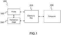
- FIG. 1 illustrates an apparatus for ultrasound imaging of a sample according to the present description, e.g. an apparatus configured to implement fUS imaging.
- the apparatus 200 generally comprises an ultrasound probe 100, an electronic bay 210, a computer 230 and an (optional) translation stage 250.
- the probe 100 is configured to emit acoustic waves into a sample and detect acoustic waves that are back-reflected by the sample.
- the probe is further configured to generate analog electrical signals from the detected acoustic waves and transfer the analog electrical signals to the computer 230 via the electronic bay 210.
- the electrical signals that are generated by the probe may be analog, whereas the signals processed by the computer may be digital. Therefore, the electronic bay 210 may perform an analog to digital conversion of the electrical signals so that they are readable and processible by the computer 230.
- the computer 230 is configured to acquire the electrical signals from the electronic bay 210 and process the electrical signals to generate images of the sample, for example images of slices of the sample (i.e. 2D images).
- the translation stage 250 is configured to move the probe 100 or parts of the probe 100 so that the apparatus can generate images of different parts of the sample.
- the translation stage may be incorporated in the probe itself.
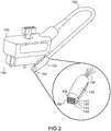
- FIG. 2 illustrates an example of an ultrasound probe 100 according to an embodiment of the present disclosure.
- the ultrasound probe 100 comprises a connector 101, a connector cable 102 and a probe head 103.
- the probe head 103 comprises a mount 105, located in a tip part 104 of the probe head 103 and a plurality of linear matrices of transducer elements (hereafter "transducers”) fixed on the mount 105.
- transducers linear matrices of transducer elements
- linear matrices 110, 120, 130, 140
- the probe could comprise more or less linear matrices, e.g. between 2 and 12, advantageously between 2 and 8, for example between 4 and 8.
- the probe head emits acoustic waves towards the sample via the linear matrices and converts the acoustic waves back-reflected by the sample into electrical signals that are sent to the connector 101 via the electric wires 106.
- the probe head 103 is electrically connected to the connector 101 through electric wires 106 comprising conductive material.
- the electric wires 106 may be protected by a connector cable 102 in order to avoid any disturbance from the environment.
- the linear matrices may be independently electrically connected to the connector.
- a multiplexer (or "MUX") configured to multiplex the emitted and/or received signals to and from the transducers may be arranged in the electronic bay or in the probe.
- FIG. 3 schematically illustrates four linear matrices (110, 120, 130, 140) of transducers in an example of an ultrasound probe according the present description.
- each linear matrix in this example has a shape of a rectangular continuous or discontinuous strip of transducers 180, with a first side along a first direction x and a second side along a second direction y, wherein x, y and z form three axes of a right handed Cartesian coordinate system.
- the second side is smaller than the first side.
- the transducers can be independently controlled in order to each emit an acoustic wave with a predefined delay with respect to the emission by the other transducers. By tuning such delays, it is possible to use interference between the acoustic waves to form a collective acoustic wave that can be selectively focused at points of a plane of the sample.
- Such technique is well known in the art as "Coherent Compound Beamforming” and described for example in G. Montaldo et al., "Coherent plane-wave compounding for very high frame rate ultrasonography and transient elastography", IEEE transactions on ultrasonics, ferroelectrics, and frequency control, 56(3), 489-506 (2009 ).
- Each linear matrix can then be used to image a slice of the sample, wherein a slice is defined in a plane comprising the first direction x and the third direction z, the third direction z being the direction along which is defined a depth within the sample.
- a slice is defined in a plane comprising the first direction x and the third direction z, the third direction z being the direction along which is defined a depth within the sample.
- Such image of a slice is referred to a "2D image" in the present description.
- the four linear matrices may insonify the sample simultaneously or sequentially, especially when a multiplexer is used.
- the linear matrices are arranged substantially parallel to one another according to the first direction (x) and a pair of juxtaposed linear matrices is separated by an inter-distance ⁇ .
- the inter-distances between contiguous linear matrices of all pairs of contiguous linear matrices may be the same.
- a non-zero inter-distance will cause the images of the slices acquired for one position of the probe to form a discontinuous 3D image of the sample comprising blind spots, i.e. parts of the sample that are not imaged but comprised between parts of the sample that are imaged.
- the acquisition time (or observation time) in each position i.e. the time required to insonify the sample and detect the backscattered acoustic waves to produce a 2D image
- a predetermined minimum observation time required for functional ultrasound imaging e.g blood flows mapping, that requires calculating 3D images at different times.
- Such predetermined minimum observation time may be equal to around 10 ms.
- the number of positions and the observation time in each position may be such that the total time required to generate the 3D images is less than a predetermined "coherence time", so that the 3D images may be used to measure the brain functional connectivity.
- the inter - distance ⁇ between two juxtaposed parallel linear matrices can be advantageously set to a value inferior to about 30 times the central wavelength, advantageously inferior to about 20 times the central wavelength, for example about 3 mm for a central wavelength equal to about 0.1 mm (respectively about 2 mm).
- the transducers of each linear matrix are arranged substantially parallel to one another.
- the transducers have a rectangular shape, with a small side ( w ) along the first direction x and a large side ( H ) along the second direction y.
- w is equal to about 0.1 mm, and more generally comprised between 0.5 and 2 times the central wavelength; H is equal to about 1.5 mm, and more generally comprised between 10 and 30 times the central wavelength.
- the form factor is comprised between about 5 and about 50, for example comprised between about 5 and about 20.
- the length of the sample along the first direction (x) impacts on the length of the part of the sample that can be imaged for a given position of the probe, i.e. the field of view of the probe. Therefore, for given transducer sides (w, H), the larger the number of transducers, the larger the field of view.
- FIG. 4 illustrates a close-up view of a tip part of an ultrasound probe according to an example, represented in the plane defined by the second direction y and the third direction z.
- each linear matrix 110, 120, 130, 140 of transducers is covered with an acoustic lens, referenced respectively 112, 122, 132, 142, that is configured to focus the emitted acoustic wave in a focal plane 170 located at a focal distance F z from the linear matrix, along the third direction z.
- the cylindrical lens comprises a cylindrical axis substantially parallel to the larger side of the linear matrix, which is the side along the first direction x.
- the linear matrices 110, 120, 130, 140 of transducers may be substantially flat, meaning that the transducers of each linear matrix are arranged in a plane.
- the linear matrices may be curved in a plane defined by the first direction (x) and the third direction (z) (e.g. convex linear matrices), wherein the slope of the linear matrix varies along the first direction.
- the transducers of each linear matrix are arranged on a curved surface and the axis of each acoustic cylindrical lens parallel to the first direction follows the curvature of said surface.
- the extent of the acoustic waves along the second direction (y) is reduced in the focal plane 170 from a length approximately equal to H (for example 1.5 mm) to an elevation length L F approximately three times smaller than H (for example 500 micrometers).
- the cylindrical lenses have the same focal length and the focal plane 170 is common to every linear matrix, however the ultrasound probe according to the present disclosure is not restricted to this case.
- Other embodiments may comprise a plurality of linear matrices that are covered with cylindrical lenses with different focal lengths. Therefore, the acoustic waves emitted by the linear matrices may be focused at different distances into the sample.
- Each ensemble comprising one linear matrix and one acoustic lens allows for imaging of a section of the sample ("slice"), whose width (along the second direction) is approximately equal to the elevation length L F , whose length along the first direction (x) is approximately equal to the length of the linear matrix along the first direction (x), and whose length along the third direction (z) depends, inter alia , on the size of the transducers along to the second direction (y) and the depth of the intended focusing of the acoustic waves (focal distance).
- the length of the section along the third direction can be comprised between about 10 times and about 200 times the central wavelength, for example equal to about 200 times the central wavelength, for example about 20 mm.
- the focusing of the acoustic waves in the first direction x is not necessary because a beamforming technique may be applied in order to focus indirectly the acoustic waves at different points in the slice of the sample.
- the focusing of the acoustic waves avoids possible overlap between the acoustic waves emitted by different linear matrices in the different sections, that could introduce disturbance in the acoustic waves emitted in the sample.
- overlap it is meant that in each section defined a given ensemble comprising one linear matrix and one acoustic lens, the ratio between an acoustic field produced by each other ensemble and the acoustic field produced by said ensemble is less than - 6dB, advantageously less than - 12dB.
- FIG. 5 schematically illustrates steps of a method of functional ultrasound imaging according to an example of the present description, for example for determining the brain connectivity.
- the method comprises the acquisition of pluralities of 2D images with an ultrasound apparatus according to the present description, wherein the mount of the probe is translated at different positions defined along the second direction.
- the ultrasound probe comprises in this example four linear matrices 110, 120, 130, 140, as illustrated for example in FIGs 3 and 4 .
- a first plurality of 2D images 510 is acquired by insonifying the sample and detecting backscattered acoustic waves during a given observation time.
- the observation time may be for example equal or greater than a minimum observation time, defined for functional ultrasound imaging. Such minimum observation time is for example equal to about 10 ms.
- an observation time comprised between about 200 ms and about 400 ms is suitable for imaging a complete cardiac cycle of a rat or a mouse.
- the first step results in the acquisition of four 2D images 510 of slices of the sample.
- a second step B the mount is moved from the first position (Position 1) to a second position (Position 2), for example using a translation stage (250, FIG. 1 ).
- the distance d between the first position and the second position may be chosen to be superior or equal to about L F so that two successive pluralities of slices acquired by the apparatus according to the present description correspond to different parts of the sample.
- the distance d between the first position and the second position may be chosen to be inferior or equal to about the sum of the length of the second side H of the linear matrices and the inter-distance ⁇ . This is to avoid that a first position of a first linear matrix be identical with the second position of a second linear matrix, which would provide redundant information on the sample.
- the motion from the first position to the second position is characterized by a given translating time.
- the translating time can advantageously be inferior or equal to about 1 s, advantageously inferior or equal to about 500 ms; a smaller translating time is suitable for moving the mount at a larger number of positions, especially for measuring brain connectivity.
- a second plurality of 2D images 520 is acquired by imaging the sample during a time equal to the observation time.
- the observation time may be the same for all the positions of the mount or may differ depending on the position of the mount.
- the same steps can be repeated (translating the mount to a new position, acquiring new slices) in order to acquire a large number of slices and reconstruct the whole sample to obtain a dense 3D ultrasound image of the sample.
- the total time can be equal to about 2.4 s, which is generally less than the coherence time and suitable for measuring the brain connectivity from all the slices.
- the move of the mount presented in relation to Fig. 5 is exemplary and not limitative.
- the different positions of the mount could be chosen in different ways.
- the positions of the mount may be defined in the way in or in the way back of the mount, thereby reducing the time required for the mount to move back to its initial position.
- the pluralities of 2D images acquired at the different positions of the mount are not acquired at the same time, therefore reconstruction of the 3D images based on such 2D images may comprise a correction of the time delay between acquisition of two 2D images.
Landscapes
- Physics & Mathematics (AREA)
- Engineering & Computer Science (AREA)
- Health & Medical Sciences (AREA)
- Life Sciences & Earth Sciences (AREA)
- Radar, Positioning & Navigation (AREA)
- Remote Sensing (AREA)
- Acoustics & Sound (AREA)
- General Physics & Mathematics (AREA)
- Pathology (AREA)
- General Health & Medical Sciences (AREA)
- Biomedical Technology (AREA)
- Computer Networks & Wireless Communication (AREA)
- Chemical & Material Sciences (AREA)
- Biophysics (AREA)
- Molecular Biology (AREA)
- Immunology (AREA)
- Biochemistry (AREA)
- Analytical Chemistry (AREA)
- Medical Informatics (AREA)
- Nuclear Medicine, Radiotherapy & Molecular Imaging (AREA)
- Surgery (AREA)
- Public Health (AREA)
- Veterinary Medicine (AREA)
- Heart & Thoracic Surgery (AREA)
- Radiology & Medical Imaging (AREA)
- Animal Behavior & Ethology (AREA)
- Optics & Photonics (AREA)
- Hematology (AREA)
- Urology & Nephrology (AREA)
- Food Science & Technology (AREA)
- Medicinal Chemistry (AREA)
- Neurology (AREA)
- Ultra Sonic Daignosis Equipment (AREA)
Priority Applications (5)
| Application Number | Priority Date | Filing Date | Title |
|---|---|---|---|
| EP20306658.4A EP4020008A1 (de) | 2020-12-22 | 2020-12-22 | Ultraschallsonden und vorrichtungen zur ultraschallbilderzeugung damit |
| CN202180087064.8A CN116868085A (zh) | 2020-12-22 | 2021-12-21 | 超声探头和包括该超声探头的用于超声成像的设备 |
| EP21836580.7A EP4267989A1 (de) | 2020-12-22 | 2021-12-21 | Ultraschallsonden und vorrichtungen zur ultraschallbildgebung damit |
| PCT/EP2021/087169 WO2022136481A1 (en) | 2020-12-22 | 2021-12-21 | Ultrasound probes and apparatuses for ultrasound imaging including such |
| US18/269,158 US20240183824A1 (en) | 2020-12-22 | 2021-12-21 | Ultrasound probes and apparatuses for ultrasound imaging including such |
Applications Claiming Priority (1)
| Application Number | Priority Date | Filing Date | Title |
|---|---|---|---|
| EP20306658.4A EP4020008A1 (de) | 2020-12-22 | 2020-12-22 | Ultraschallsonden und vorrichtungen zur ultraschallbilderzeugung damit |
Publications (1)
| Publication Number | Publication Date |
|---|---|
| EP4020008A1 true EP4020008A1 (de) | 2022-06-29 |
Family
ID=74191490
Family Applications (2)
| Application Number | Title | Priority Date | Filing Date |
|---|---|---|---|
| EP20306658.4A Withdrawn EP4020008A1 (de) | 2020-12-22 | 2020-12-22 | Ultraschallsonden und vorrichtungen zur ultraschallbilderzeugung damit |
| EP21836580.7A Pending EP4267989A1 (de) | 2020-12-22 | 2021-12-21 | Ultraschallsonden und vorrichtungen zur ultraschallbildgebung damit |
Family Applications After (1)
| Application Number | Title | Priority Date | Filing Date |
|---|---|---|---|
| EP21836580.7A Pending EP4267989A1 (de) | 2020-12-22 | 2021-12-21 | Ultraschallsonden und vorrichtungen zur ultraschallbildgebung damit |
Country Status (4)
| Country | Link |
|---|---|
| US (1) | US20240183824A1 (de) |
| EP (2) | EP4020008A1 (de) |
| CN (1) | CN116868085A (de) |
| WO (1) | WO2022136481A1 (de) |
Families Citing this family (1)
| Publication number | Priority date | Publication date | Assignee | Title |
|---|---|---|---|---|
| USD1059595S1 (en) * | 2019-10-03 | 2025-01-28 | GE Precision Healthcare LLC | Medical imaging device |
Citations (2)
| Publication number | Priority date | Publication date | Assignee | Title |
|---|---|---|---|---|
| US20070167823A1 (en) * | 2005-12-20 | 2007-07-19 | General Electric Company | Imaging catheter and method for volumetric ultrasound |
| US20090292208A1 (en) * | 2008-03-03 | 2009-11-26 | Jeffrey Jr R Brooke | Automated detection of asymptomatic carotid stenosis |
Family Cites Families (5)
| Publication number | Priority date | Publication date | Assignee | Title |
|---|---|---|---|---|
| US5924986A (en) * | 1997-09-10 | 1999-07-20 | Acuson Corporation | Method and system for coherent ultrasound imaging of induced, distributed source, bulk acoustic emissions |
| JP4839136B2 (ja) * | 2006-06-02 | 2011-12-21 | 富士フイルム株式会社 | 超音波トランスデューサアレイ、超音波用探触子、超音波内視鏡、超音波診断装置 |
| GB201513024D0 (en) * | 2015-07-23 | 2015-09-09 | Univ Heriot Watt | A method of, and apparatus for, determination of position in ultrasound imaging |
| JP2017080130A (ja) * | 2015-10-29 | 2017-05-18 | セイコーエプソン株式会社 | 超音波デバイス、超音波プローブ、および超音波画像装置 |
| EP3494893A1 (de) * | 2017-12-05 | 2019-06-12 | Koninklijke Philips N.V. | Ultraschallbildgebungssystem und -verfahren |
-
2020
- 2020-12-22 EP EP20306658.4A patent/EP4020008A1/de not_active Withdrawn
-
2021
- 2021-12-21 WO PCT/EP2021/087169 patent/WO2022136481A1/en not_active Ceased
- 2021-12-21 CN CN202180087064.8A patent/CN116868085A/zh active Pending
- 2021-12-21 US US18/269,158 patent/US20240183824A1/en active Pending
- 2021-12-21 EP EP21836580.7A patent/EP4267989A1/de active Pending
Patent Citations (2)
| Publication number | Priority date | Publication date | Assignee | Title |
|---|---|---|---|---|
| US20070167823A1 (en) * | 2005-12-20 | 2007-07-19 | General Electric Company | Imaging catheter and method for volumetric ultrasound |
| US20090292208A1 (en) * | 2008-03-03 | 2009-11-26 | Jeffrey Jr R Brooke | Automated detection of asymptomatic carotid stenosis |
Non-Patent Citations (5)
| Title |
|---|
| G. MONTALDO ET AL.: "Coherent plane-wave compounding for very high frame rate ultrasonography and transient elastography", IEEE TRANSACTIONS ON ULTRASONICS, FERROELECTRICS, AND FREQUENCY CONTROL, vol. 56, no. 3, 2009, pages 489 - 506, XP011255897 |
| GESNIK, MARCBLAIZE, KEVINDEFFIEUX, THOMAS ET AL.: "3D functional ultrasound imaging of the cerebral visual system in rodents", NEUROLMAGE, vol. 149, 2017, pages 267 - 274, XP029957974, DOI: 10.1016/j.neuroimage.2017.01.071 |
| OSMANSKI, BRUNO FELIXPEZET, SOPHIERICOBARAZA, ANA ET AL.: "Functional ultrasound imaging of intrinsic connectivity in the living rat brain with high spatiotemporal resolution", NATURE COMMUNICATIONS, vol. 5, no. 1, 2014, pages 1 - 14 |
| RABUT, CLAIRECORREIA, MAFALDAFINEL, VICTOR ET AL.: "4D functional ultrasound imaging of whole-brain activity in rodents", NATURE METHODS, vol. 16, no. 10, 2019, pages 994 - 997, XP036887820, DOI: 10.1038/s41592-019-0572-y |
| SAUVAGE, JACKPOREE, JONATHANRABUT, CLAIRE ET AL.: "4D Functional imaging of the rat brain using a large aperture row-column array", IEEE TRANSACTIONS ON MEDICAL IMAGING, 2019 |
Also Published As
| Publication number | Publication date |
|---|---|
| WO2022136481A1 (en) | 2022-06-30 |
| CN116868085A (zh) | 2023-10-10 |
| US20240183824A1 (en) | 2024-06-06 |
| EP4267989A1 (de) | 2023-11-01 |
Similar Documents
| Publication | Publication Date | Title |
|---|---|---|
| US12285294B2 (en) | Shear wave elastrography method and apparatus for imaging an anisotropic medium | |
| KR101820422B1 (ko) | 포커싱되지 않은 송신 빔들을 이용한 높은 프레임 레이트의 정량적 도플러 흐름 촬영 | |
| JP6932192B2 (ja) | 超音波画像クラッタをフィルタリングする方法及びシステム | |
| US8998812B2 (en) | Ultrasound method and probe for electromagnetic noise cancellation | |
| US6464638B1 (en) | Ultrasound imaging system and method for spatial compounding | |
| US4105018A (en) | Acoustic examination, material characterization and imaging of the internal structure of a body by measurement of the time-of-flight of acoustic energy therethrough | |
| EP0500801B1 (de) | Verfahren und vorrichtung zur messung und darstellung der gewebekompressibilität oder nachgiebigkeit | |
| EP2437666B1 (de) | Verfahren und vorrichtung zur messung der kontraktilität des herzens | |
| CN101797165B (zh) | 超声波诊断装置及超声波诊断装置的控制方法 | |
| CN113507891A (zh) | 超声成像系统 | |
| JPH11221217A (ja) | 超音波診断装置 | |
| KR20180013956A (ko) | 단일 추적 위치 전단파 탄성 이미징을 위한 방법, 시스템 및 컴퓨터 프로그램 제품 | |
| JP2021522011A (ja) | 超音波スクリーニングのためのシステム及び方法 | |
| JP2007222253A (ja) | 血流画像表示装置 | |
| JP4074100B2 (ja) | 超音波画像診断装置 | |
| KR20190087041A (ko) | 초음파 영상장치 및 그 제어방법 | |
| EP4020008A1 (de) | Ultraschallsonden und vorrichtungen zur ultraschallbilderzeugung damit | |
| KR20140137037A (ko) | 초음파 영상 처리 장치 및 방법 | |
| JP5930611B2 (ja) | 被検体情報取得装置 | |
| CN118873174B (zh) | 一种实时三维超声弹性成像的系统和方法 | |
| JP7301676B2 (ja) | 超音波診断装置、信号処理方法、及び信号処理プログラム | |
| KR102704209B1 (ko) | 초음파 영상장치 및 그 제어방법 | |
| US20160157728A1 (en) | Acoustic-electric imaging method and device | |
| Wang et al. | Enhancing Image Contrast in Breast USCT Reflection Imaging Using Coherence Factor Beamforming | |
| JP2005095221A (ja) | 超音波骨計測装置及び骨計測方法 |
Legal Events
| Date | Code | Title | Description |
|---|---|---|---|
| PUAI | Public reference made under article 153(3) epc to a published international application that has entered the european phase |
Free format text: ORIGINAL CODE: 0009012 |
|
| STAA | Information on the status of an ep patent application or granted ep patent |
Free format text: STATUS: THE APPLICATION HAS BEEN PUBLISHED |
|
| AK | Designated contracting states |
Kind code of ref document: A1 Designated state(s): AL AT BE BG CH CY CZ DE DK EE ES FI FR GB GR HR HU IE IS IT LI LT LU LV MC MK MT NL NO PL PT RO RS SE SI SK SM TR |
|
| STAA | Information on the status of an ep patent application or granted ep patent |
Free format text: STATUS: THE APPLICATION IS DEEMED TO BE WITHDRAWN |
|
| 18D | Application deemed to be withdrawn |
Effective date: 20230103 |