EP4020003A1 - Verfahren und vorrichtung zur bestimmung des phasenfehlers eines phasenschiebers - Google Patents
Verfahren und vorrichtung zur bestimmung des phasenfehlers eines phasenschiebers Download PDFInfo
- Publication number
- EP4020003A1 EP4020003A1 EP21290043.5A EP21290043A EP4020003A1 EP 4020003 A1 EP4020003 A1 EP 4020003A1 EP 21290043 A EP21290043 A EP 21290043A EP 4020003 A1 EP4020003 A1 EP 4020003A1
- Authority
- EP
- European Patent Office
- Prior art keywords
- phase
- values
- successive
- sequence
- value
- Prior art date
- Legal status (The legal status is an assumption and is not a legal conclusion. Google has not performed a legal analysis and makes no representation as to the accuracy of the status listed.)
- Granted
Links
Images
Classifications
-
- G—PHYSICS
- G01—MEASURING; TESTING
- G01S—RADIO DIRECTION-FINDING; RADIO NAVIGATION; DETERMINING DISTANCE OR VELOCITY BY USE OF RADIO WAVES; LOCATING OR PRESENCE-DETECTING BY USE OF THE REFLECTION OR RERADIATION OF RADIO WAVES; ANALOGOUS ARRANGEMENTS USING OTHER WAVES
- G01S7/00—Details of systems according to groups G01S13/00, G01S15/00, G01S17/00
- G01S7/02—Details of systems according to groups G01S13/00, G01S15/00, G01S17/00 of systems according to group G01S13/00
- G01S7/023—Interference mitigation, e.g. reducing or avoiding non-intentional interference with other HF-transmitters, base station transmitters for mobile communication or other radar systems, e.g. using electro-magnetic interference [EMI] reduction techniques
- G01S7/0233—Avoidance by phase multiplex
-
- G—PHYSICS
- G01—MEASURING; TESTING
- G01S—RADIO DIRECTION-FINDING; RADIO NAVIGATION; DETERMINING DISTANCE OR VELOCITY BY USE OF RADIO WAVES; LOCATING OR PRESENCE-DETECTING BY USE OF THE REFLECTION OR RERADIATION OF RADIO WAVES; ANALOGOUS ARRANGEMENTS USING OTHER WAVES
- G01S7/00—Details of systems according to groups G01S13/00, G01S15/00, G01S17/00
- G01S7/02—Details of systems according to groups G01S13/00, G01S15/00, G01S17/00 of systems according to group G01S13/00
- G01S7/40—Means for monitoring or calibrating
- G01S7/4004—Means for monitoring or calibrating of parts of a radar system
- G01S7/4008—Means for monitoring or calibrating of parts of a radar system of transmitters
-
- G—PHYSICS
- G01—MEASURING; TESTING
- G01S—RADIO DIRECTION-FINDING; RADIO NAVIGATION; DETERMINING DISTANCE OR VELOCITY BY USE OF RADIO WAVES; LOCATING OR PRESENCE-DETECTING BY USE OF THE REFLECTION OR RERADIATION OF RADIO WAVES; ANALOGOUS ARRANGEMENTS USING OTHER WAVES
- G01S13/00—Systems using the reflection or reradiation of radio waves, e.g. radar systems; Analogous systems using reflection or reradiation of waves whose nature or wavelength is irrelevant or unspecified
- G01S13/88—Radar or analogous systems specially adapted for specific applications
- G01S13/93—Radar or analogous systems specially adapted for specific applications for anti-collision purposes
- G01S13/931—Radar or analogous systems specially adapted for specific applications for anti-collision purposes of land vehicles
-
- G—PHYSICS
- G01—MEASURING; TESTING
- G01S—RADIO DIRECTION-FINDING; RADIO NAVIGATION; DETERMINING DISTANCE OR VELOCITY BY USE OF RADIO WAVES; LOCATING OR PRESENCE-DETECTING BY USE OF THE REFLECTION OR RERADIATION OF RADIO WAVES; ANALOGOUS ARRANGEMENTS USING OTHER WAVES
- G01S7/00—Details of systems according to groups G01S13/00, G01S15/00, G01S17/00
- G01S7/02—Details of systems according to groups G01S13/00, G01S15/00, G01S17/00 of systems according to group G01S13/00
- G01S7/40—Means for monitoring or calibrating
Definitions
- the present disclosure relates to the field of radar detection. More specifically, the present disclosure relates to methods and devices for determining phase error caused by impairments in a phase rotator, said impairments including leakage in mixers and/or multipliers of the phase rotator, gain/amplitude imbalance and phase imbalance between an I path and a Q path in the phase rotator. Furthermore, the present disclosure relates to a radar system capable of determining phase error caused by impairments in a phase rotator, said impairments including leakage in mixers and/or multipliers of the phase rotator, gain/amplitude imbalance and a phase imbalance between an I path and a Q path in the phase rotator.
- Beam steering is intensively used in FMCW radar detection to improve the overall radar performance. Beam steering involves controlling the direction of the antenna arrays to reinforce the main lobe of a radar radiation pattern. This is done by controlling the phase and the amplitude of the array antennas of the radar solution. Phase and amplitude of the radiation pattern may e.g. be digitally controlled through a phase rotator. Any distortions from the programmed phase and amplitude will degrade the radar performance. In many applications, such as radar-based collision detection systems for automotive vehicles, such degradations have to be kept at a minimum in order to assure safe operation and reliability of the systems.
- a method of determining phase error caused by impairments in a phase rotator said impairments including leakage in mixers and/or multipliers of the phase rotator, gain/amplitude imbalance and a known phase imbalance between an I path and a Q path in the phase rotator, the phase rotator having an input for receiving a reference phase value, a local oscillator and circuitry configured to provide an output signal with a phase corresponding to the reference phase value.
- the method comprises (a) forcing the Q path of the phase rotator to zero and obtaining a first sequence of successive measurement values indicative of a power of the phase rotator output signal, each successive measurement value in the first sequence corresponding to one of a plurality of successive reference phase values, (b) forcing the I path of the phase rotator to zero and obtaining a second sequence of successive measurement values indicative of the power of the phase rotator output signal, each successive measurement value in the second sequence corresponding to one of the plurality of successive reference phase values, (c) forming a sequence of successive measurement value pairs, each measurement value pair comprising one measurement value from the first sequence of successive measurement values and one measurement value from the second sequence of successive measurement values, wherein the first sequence of successive measurement values is shifted relative to the second sequence of successive measurement values by an amount corresponding to the known phase imbalance, (d) calculating an actual phase value for each of the successive measurement value pairs, and (e) determining the phase error by comparing the actual phase values with the corresponding reference phase values.
- This aspect is based on the idea that two measurement sequences are performed for a number of successive reference phase values (i.e. input values to the phase rotator), i.e. a first sequence where the Q path of the phase rotator is forced to zero and a second sequence where the I path of the phase rotator is forced to zero.
- the first sequence of successive measurement values contains values originating only from the I path of the phase rotator
- the second sequence of successive measurement values contains values originating only from the Q path of the phase rotator.
- Each single measurement value is indicative of the power of the output signal from the phase rotator. Then, the two sequences are shifted relative to each other to form a sequence of successive measurement value pairs.
- the i-th measurement value of the first sequence may be paired with the (i+k)-th measurement value of the second sequence.
- the amount of shifting k is determined such that it corresponds to the known phase imbalance.
- the known phase imbalance can be determined in various ways known in the art. In the framework of the present disclosure, the phase imbalance can be determined as a phase offset that must be applied to one of the I and Q paths in order to yield the same output power from the phase rotator when the phase reference is set to +45° and -45°, respectively. This determination can be carried out iteratively as follows:
- phase error is calculated for the pairs of measurement values and compared with the corresponding reference phase values to determine the phase error.
- phase imbalance i.e. the shift in phase between the I and Q paths
- gain imbalance i.e. the gain difference between the I and Q paths
- leakage in the I mixer/multiplier i.e. the leakage introduced by the mixer inputs on the I path
- leakage on the Q mixer/multiplier i.e. the leakage introduced by the mixer inputs on the Q path.
- the maximum of the resulting phase error depends on the actual phase reference (input value to the phase rotator) for each of the four contributors.
- the phase reference that gives a max phase error for phase imbalance may be different from the phase reference that gives a max phase error for the gain imbalance.
- the actual phase error is not the sum of the individual phase error introduced by each of the four contributors. Instead, the phase error is a combination of the individual contributors. The present disclosure enables a determination of this combination.
- the plurality of successive reference phase values comprises successive reference phase values from 0° to 360° with a predetermined reference phase step value separating any two successive reference phase values.
- the phase step value may be equal to 360°/512 - 0.7°, resulting in successive phase reference values equal to 0°, 0.7°, 1.4°, 2.1° and so on.
- the plurality of successive reference phase values is provided as a sweep during a predetermined period of time.
- the reference phase value is successively increased from 0° to 360° during the predetermined period of time, e.g. by adding a fixed phase step value to the phase reference value at regular tune intervals.
- the amount of shifting that corresponds to the known amount of phase imbalance is determined as the number of values in the plurality of successive reference phase values divided by 360 and multiplied by the known amount of phase imbalance.
- N the number of values
- Phi_imb the known phase imbalance
- the amount of shifting is given as (N/360°)*Phi_imb.
- the first and second sequences of successive measurement values will be shifted by 7 (seven) relative to one another when forming the sequence of successive measurement value pairs.
- calculating the actual phase value for each of the successive measurement value pairs comprises applying an arctan function to the ratio between the measurement value from the second sequence of successive measurement values and the measurement value from the first sequence of successive measurement values of each successive measurement value pair.
- the i-th actual phase value may be calculated as arctan(Q i /I i-k ) where Q i is the i-th measurement value in the second sequence of successive measurement values and I i-k is the (i-k)-th measurement value in the first sequence of successive measurement values.
- the method further comprises: comparing the determined phase error with a phase error threshold value, and setting a warning flag if the determined phase error exceeds the phase error threshold value.
- a warning flag is set such that the system is made aware of the reduced and possibly insufficient precision of the phase rotator.
- a device for determining phase error caused by impairments in a phase rotator said impairments including leakage in mixers and/or multipliers of the phase rotator, a gain/amplitude imbalance and a known phase imbalance between an I path and a Q path in the phase rotator, the phase rotator having an input for receiving a reference phase value, a local oscillator and circuitry configured to provide an output signal with a phase corresponding to the reference phase value.
- the device comprises (a) a power meter coupled to receive the phase rotator output signal and configured to output a measurement value indicative of a power of the phase rotator output signal, (b) a memory circuit configured to store measurement values output by the power meter, (c) control circuitry configured to provide a plurality of successive reference phase values to the input of the phase rotator, the control circuitry further configured to: (c1) force the Q path of the phase rotator to zero, obtain a first sequence of successive measurement values from the power meter, each successive measurement value in the first sequence corresponding to one of the plurality of successive reference phase values, and store the first sequence of successive measurement values in the memory circuit, and (c2) force the 1 path of the phase rotator to zero, obtain a second sequence of successive measurement values from the power meter, each successive measurement value in the second sequence corresponding to one of the plurality of successive reference phase values, and store the second sequence of successive measurement values in the memory circuit, the device further comprising (d) processing circuitry configured to: (d1) form a sequence
- This aspect is essentially based on the same idea as the first aspect discussed above and provides a device capable of implementing and performing the method according to the first aspect.
- the plurality of successive reference phase values comprises successive reference phase values from 0° to 360° with a predetermined reference phase step value separating any two successive reference phase values.
- control circuitry is configured to provide the plurality of successive reference phase values is provided as a sweep during a predetermined period of time.
- control circuitry successively increases the reference phase value from 0° to 360° during the predetermined period of time, e.g. by adding a fixed phase step value to the phase reference value at regular time intervals.
- the processing circuitry is configured to determine the amount of shifting that corresponds to the known amount of phase imbalance as the number of values in the plurality of successive reference phase values divided by 360 and multiplied by the known amount of phase imbalance.
- N the number of values
- Phi_imb the known phase imbalance
- the amount of shifting is given as (N/360°)*Phi_imb.
- the first and second sequences of successive measurement values will be shifted by 7 relative to one another when forming the sequence of successive measurement value pairs.
- the processing circuitry is configured to calculate the actual phase value for each of the successive measurement value pairs by applying an arctan function to the ratio between the measurement value from the second sequence of successive measurement values and the measurement value from the first sequence of successive measurement values of each successive measurement value pair.
- the processing circuitry may calculate the i-th actual phase value as arctan(Q i /I i-k ) where Q i is the i-th measurement value in the second sequence of successive measurement values and I i-k is the (i-k)-th measurement value in the first sequence of successive measurement values.
- the processing circuitry is further configured to compare the determined phase error with a phase error threshold value, and to set a warning flag if the determined phase error exceeds the phase error threshold value.
- a warning flag is set such that the system is made aware of the reduced and possibly insufficient precision of the phase rotator.
- a radar system comprising: (a) a phase rotator having an input for receiving a reference phase value, a local oscillator and circuitry configured to provide an output signal with a phase corresponding to the reference phase value, (b) a power amplifier coupled to receive the output signal from the phase rotator, amplify said output signal and supply the amplified signal to one of a plurality of radar antennas, and (c) a device for determining phase error caused by impairments in the phase rotator, said impairments including leakage in mixers and/or multipliers of the phase rotator, a gain/amplitude imbalance and a known phase imbalance between an I path and a Q path in the phase rotator, the device comprising: (d) a power meter coupled to receive the phase rotator output signal and configured to output a measurement value indicative of a power of the phase rotator output signal, (e) a memory circuit configured to store measurement values output by the power meter, (f) control circuitry configured to
- This aspect is essentially based on the same idea as the first and second aspects described above and provides a radar system comprising a device according to the second aspect.
- the plurality of successive reference phase values comprises successive reference phase values from 0° to 360° with a predetermined reference phase step value separating any two successive reference phase values.
- control circuitry is configured to provide the plurality of successive reference phase values is provided as a sweep during a predetermined period of time.
- control circuitry successively increases the reference phase value from 0° to 360° during the predetermined period of time, e.g. by adding a fixed phase step value to the phase reference value at regular time intervals.
- the processing circuitry is configured to determine the amount of shifting that corresponds to the known amount of phase imbalance as the number of values in the plurality of successive reference phase values divided by 360 and multiplied by the known amount of phase imbalance.
- N the number of values
- Phi_imb the known phase imbalance
- the amount of shifting is given as (N/360°)*Phi_imb.
- the first and second sequences of successive measurement values will be shifted by 7 relative to one another when forming the sequence of successive measurement value pairs.
- the processing circuitry is configured to calculate the actual phase value for each of the successive measurement value pairs by applying an arctan function to the ratio between the measurement value from the second sequence of successive measurement values and the measurement value from the first sequence of successive measurement values of each successive measurement value pair.
- the processing circuitry may calculate the i-th actual phase value as arctan(Q i /I i-k ) where Q i is the i-th measurement value in the second sequence of successive measurement values and I i-k is the (i-k)-th measurement value in the first sequence of successive measurement values.
- the processing circuitry is further configured to compare the determined phase error with a phase error threshold value, and to set a warning flag if the determined phase error exceeds the phase error threshold value.
- a warning flag is set such that the system is made aware of the reduced and possibly insufficient precision of the phase rotator.
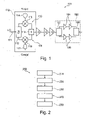
- FIG. 1 shows a diagram of a typical radar system 101 utilizing a phase rotator 110 as known in the art, such as an automotive radar for preventing collisions.
- the phase rotator 110 comprises an input 111, an I/Q splitter 112, an I path (or in-phase path) 113, a Q path (or quadrature path) 116, and an adder 119.
- the IQ splitter 112 is configured to receive an input signal provided to the input 111 by a local oscillator LO.
- the I path 113 comprises a multiplier 115 coupled between one output of I/Q splitter 111 and one input of adder 119 and configured to multiply the signal output by I/Q splitter 112 with sin( ⁇ ) which is received at terminal 114.
- ⁇ denotes a reference phase value indicating the desired phase of the output from the phase rotator 110 relative to the original phase of the signal from LO.
- the Q path 116 comprises a multiplier 11.8 coupled between the other output of I/Q splitter 111 and the other input of adder 119 and configured to multiply the signal output by I/Q splitter 112 with cos( ⁇ ) which is received at terminal 117.
- ⁇ is the reference phase value.
- the output signal from the phase rotator 110 is sent through a series of buffers G and supplied to a power amplifier 190.
- the shown power amplifier 190 comprises an I/Q splitter 192, a first series of amplifiers 194 coupled to amplify the I component, a second series of amplifiers 196 coupled to amplify the Q component, and a combiner 198 for combining the amplified I and Q components and supply it to a radar antenna array (not shown) as known in the art.
- phase rotator 110 introduces some phase error, i.e. deviation from the desired phase, due to various impairments or imperfections of the phase rotator 110.
- phase rotator impairments in particular include (i) gain/amplitude imbalance between the 1 path 113 and the Q path 116, (ii) phase imbalance between the I path 113 and the Q path 116, and (iii) leakage at multipliers 115 and 118.
- the present disclosure presents a way to measure the phase error due to the phase rotator impairments mentioned above, i.e. leakage in the mixers and/or multipliers, gain imbalance and a known phase imbalance
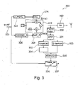
- Figure 2 shows a flowchart of a method 202 of determining phase error according to an exemplary embodiment, the phase error being caused by impairments in a phase rotator, said impairments including leakage in mixers and/or multipliers of the phase rotator, gain/amplitude imbalance and a known phase imbalance between an I path and a Q path in the phase rotator, the phase rotator having an input for receiving a reference phase value, a local oscillator and circuitry configured to provide an output signal with a phase corresponding to the reference phase value.
- the method 202 comprises the following steps:
- the plurality of successive reference phase values may comprise successive reference phase values from 0° to 360° with a predetermined reference phase step value separating any two successive reference phase values.
- the plurality of successive reference phase values may be provided as a sweep during a predetermined period of time, i.e. the reference phase value may be successively increased from 0° to 360° during the predetermined period of time, e.g. by adding a fixed phase step value to the phase reference value at regular time intervals.
- the amount of shifting that corresponds to the known amount of phase imbalance may be determined as the number of values in the plurality of successive reference phase values divided by 360 and multiplied by the known amount of phase imbalance.
- N the number of values
- Phi_imb the known phase imbalance
- the amount of shifting is given as (N/360°)*Phi_imb.
- N the number of values
- Phi_imb the known phase imbalance
- the first and second sequences of successive measurement values will be shifted by 7 relative to one another when forming the sequence of successive measurement value pairs.
- Calculating the actual phase value for each of the successive measurement value pairs may comprise applying an arctan function to the ratio between the measurement value from the second sequence of successive measurement values and the measurement value from the first sequence of successive measurement values of cach successive measurement value pair.
- the i-th actual phase value may be calculated as arotan(Q i /I i-k ) where Q i is the i-th measurement value in the second sequence of successive measurement values and I i-k is the (i-k)-th measurement value in the first sequence of successive measurement values.
- the method 202 may further comprise comparing the determined phase error with a phase error threshold value and setting a warning flag if the determined phase error exceeds the phase error threshold value.
- a warning flag is set such that the system is made aware of the reduced and possibly insufficient precision of the phase rotator.
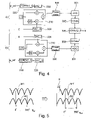
- FIG 3 shows a diagram of a device for determining phase error according to an exemplary embodiment within a radar system 303.
- the radar system 303 like the radar system 101 shown in Figure 1 and discussed above, comprises a phase rotator 310 and a power amplifier 390 for supplying a signal with a predetermined phase to a radar antenna.
- the phase rotator 310 is coupled to circuitry for supplying the sin( ⁇ ) and cos( ⁇ )) factors to be multiplied onto the I and Q paths within the phase rotator 310. More specifically, said circuitry comprises a CORDIC circuit 322 and a DAC 324 for supplying sin( ⁇ ) corresponding to phase reference value ⁇ _ref received at input terminal 320. Furthermore, said circuitry comprises a CORDIC circuit 326 and a DAC 328 for supplying cos( ⁇ ) corresponding to the phase reference value ⁇ _ref.
- the actual device for determining phase error comprises circuitry blocks 330, 331, 332, 333, 334, 335, 336, and 337. More specifically, the device comprises a power meter 330 coupled to receive the phase rotator output signal and configured to output a measurement value indicative of a power of the phase rotator output signal to ADC 331. The device further comprises a memory circuit including I memory 332 and Q memory configured to store corresponding measurement values output from the power meter 330 through the ADC 331.
- the calculated actual phase value is supplied to circuit 336 which also receives the reference phase value ⁇ _ref and thereby calculates the sought phase error by comparing (e.g. subtracting) the two received phase values.
- the device also comprises a controller (not shown) configured to override the circuits 322 and 326 during measurement in accordance with the method 202 discussed above and to set an error flag if the determined phase error exceeds a threshold value.
- Figure 4 illustrates the function of the device shown in Figure 3 when operated in accordance with the method 202 shown in Figure 2 . More specifically, Figure 4 shows the device in a first state a) corresponding to step 210 in Figure 2 and a second state b) corresponding to step 220 in Figure 2 .
- state a) the Q path of the phase rotator 310 is set to zero while a sequence of successive reference phase values ⁇ _ref is supplied to the I path of phase rotator 310 through CORDIC circuit 322 and a DAC 324.
- a first sequence of successive measurement values is obtained by the power meter 330 and ADC 332 and stored in memory circuit 332.
- the I path of the phase rotator 310 is set to zero while the same sequence of successive reference phase values ⁇ _ref is supplied to the Q path of phase rotator 310 through CORDIC circuit 326 and a DAC 328.
- a second sequence of successive measurement values is obtained by the power meter 330 and ADC 332 and stored in memory circuit 333.
- the data stored in memory circuits 332 and 333 is processed as previously described to determine the resulting phase error.
- the right-hand diagram of Figure 5 the result of shifting (delaying) the first sequence of successive measurement values M1 by an amount S corresponding to the known phase imbalance of the phase rotator 310 is shown. As can be seen, the maximum values in the shifted sequence M1' no longer corresponds to the minimum values in the second sequence M2.
Landscapes
- Engineering & Computer Science (AREA)
- Radar, Positioning & Navigation (AREA)
- Remote Sensing (AREA)
- Computer Networks & Wireless Communication (AREA)
- Physics & Mathematics (AREA)
- General Physics & Mathematics (AREA)
- Electromagnetism (AREA)
- Measuring Phase Differences (AREA)
- Radar Systems Or Details Thereof (AREA)
Priority Applications (2)
| Application Number | Priority Date | Filing Date | Title |
|---|---|---|---|
| US17/451,828 US12061282B2 (en) | 2020-12-22 | 2021-10-22 | Method, device, and radar system |
| CN202111577138.4A CN114660608A (zh) | 2020-12-22 | 2021-12-22 | 方法、装置和雷达系统 |
Applications Claiming Priority (1)
| Application Number | Priority Date | Filing Date | Title |
|---|---|---|---|
| EP20290089.0A EP4020002A1 (de) | 2020-12-22 | 2020-12-22 | Verfahren und vorrichtung zur bestimmung des phasenfehlers eines phasenschiebers |
Publications (2)
| Publication Number | Publication Date |
|---|---|
| EP4020003A1 true EP4020003A1 (de) | 2022-06-29 |
| EP4020003B1 EP4020003B1 (de) | 2025-09-10 |
Family
ID=74946919
Family Applications (2)
| Application Number | Title | Priority Date | Filing Date |
|---|---|---|---|
| EP20290089.0A Withdrawn EP4020002A1 (de) | 2020-12-22 | 2020-12-22 | Verfahren und vorrichtung zur bestimmung des phasenfehlers eines phasenschiebers |
| EP21290043.5A Active EP4020003B1 (de) | 2020-12-22 | 2021-06-28 | Verfahren und vorrichtung zur bestimmung des phasenfehlers eines phasenschiebers |
Family Applications Before (1)
| Application Number | Title | Priority Date | Filing Date |
|---|---|---|---|
| EP20290089.0A Withdrawn EP4020002A1 (de) | 2020-12-22 | 2020-12-22 | Verfahren und vorrichtung zur bestimmung des phasenfehlers eines phasenschiebers |
Country Status (3)
| Country | Link |
|---|---|
| US (1) | US12061282B2 (de) |
| EP (2) | EP4020002A1 (de) |
| CN (1) | CN114660608A (de) |
Families Citing this family (3)
| Publication number | Priority date | Publication date | Assignee | Title |
|---|---|---|---|---|
| DE102021117540A1 (de) * | 2021-07-07 | 2023-01-12 | Infineon Technologies Ag | Radarvorrichtung und verfahren zur erkennung von hardwarefehlern eines radarvorrichtung |
| EP4490740A4 (de) * | 2022-03-09 | 2026-03-04 | Bio Rad Laboratories Inc | System und verfahren zur dynamischen anpassung der analytischen präzision bei klinischen diagnoseverfahren |
| EP4571351A1 (de) * | 2023-12-13 | 2025-06-18 | Nxp B.V. | Verfahren und vorrichtung zur selbstkalibrierung eines hochfrequenzsenders |
Citations (3)
| Publication number | Priority date | Publication date | Assignee | Title |
|---|---|---|---|---|
| US20070058702A1 (en) * | 2003-05-30 | 2007-03-15 | Yifeng Zhang | Method and device for estimating iq imbalance |
| US9923269B1 (en) * | 2015-06-30 | 2018-03-20 | Rockwell Collins, Inc. | Phase position verification system and method for an array antenna |
| US20200158821A1 (en) * | 2018-11-20 | 2020-05-21 | Nxp Usa, Inc. | Phase rotator calibration of a multichannel radar transmitter |
Family Cites Families (21)
| Publication number | Priority date | Publication date | Assignee | Title |
|---|---|---|---|---|
| US6421398B1 (en) | 2000-01-28 | 2002-07-16 | Alcatel Canada Inc. | Modulation system having on-line IQ calibration |
| US20030128660A1 (en) | 2002-01-09 | 2003-07-10 | Atsushi Ito | OFDM communications apparatus, OFDM communications method, and OFDM communications program |
| US7379520B2 (en) | 2002-04-01 | 2008-05-27 | Broadcom Corporation | Low jitter phase rotator |
| US7130359B2 (en) * | 2002-03-12 | 2006-10-31 | Motorola Inc. | Self calibrating receive path correction system in a receiver |
| US7092454B2 (en) | 2002-08-14 | 2006-08-15 | Intel Corporation | Method and apparatus of compensating imbalance of a modulator |
| US7397865B2 (en) | 2003-04-02 | 2008-07-08 | Agilent Technologies, Inc. | Systems and methods of using IQ modulation for calibration or measurement |
| US7915954B2 (en) | 2004-01-16 | 2011-03-29 | Qualcomm, Incorporated | Amplifier predistortion and autocalibration method and apparatus |
| US7680234B2 (en) * | 2004-02-24 | 2010-03-16 | Schneider Electric USA, Inc. | Method and apparatus for signal phase locking |
| US7831220B2 (en) | 2005-07-26 | 2010-11-09 | Broadcom Corporation | Methods and systems for calibrating for gain and phase imbalance and local oscillator feed-through |
| US20080074307A1 (en) * | 2006-05-17 | 2008-03-27 | Olga Boric-Lubecke | Determining presence and/or physiological motion of one or more subjects within a doppler radar system |
| US7801502B2 (en) * | 2006-12-18 | 2010-09-21 | Aai Corporation | Method for implementing continuous radio frequency (RF) alignment in advanced electronic warfare (EW) signal stimulation systems |
| US20120244824A1 (en) | 2007-02-12 | 2012-09-27 | Texas Instruments Incorporated | Minimization of rms phase error in a phase locked loop by dithering of a frequency reference |
| US7986925B2 (en) | 2008-08-14 | 2011-07-26 | Freescale Semiconductor, Inc. | Techniques for calibrating a transceiver of a communication device |
| US8351492B2 (en) | 2011-01-05 | 2013-01-08 | Qualcomm Incorporated | Estimation of intentional phase shift in a calibration apparatus |
| JP5950903B2 (ja) * | 2011-03-14 | 2016-07-13 | 古河電気工業株式会社 | 直交復調装置 |
| CN103477570B (zh) | 2011-08-02 | 2016-04-27 | 松下电器产业株式会社 | 相控阵发送装置 |
| US8976914B2 (en) * | 2012-07-27 | 2015-03-10 | Texas Instruments Incorporated | Multi-tap IQ imbalance estimation and correction circuit and method |
| JP6650599B2 (ja) | 2016-03-29 | 2020-02-19 | パナソニックIpマネジメント株式会社 | フェーズドアレイ送信装置及びキャリアリーク補正方法 |
| US9819412B1 (en) * | 2016-05-04 | 2017-11-14 | Inphi Corporation | Transmitter gain imbalance and skew optimization for coherent transmitters |
| US10816655B2 (en) * | 2016-12-07 | 2020-10-27 | Texas Instruments Incorporated | In-phase (I) and quadrature (Q) imbalance estimation in a radar system |
| EP3754360B1 (de) | 2019-06-21 | 2026-01-07 | NXP USA, Inc. | Eingebaute selbsttest-sender-phasenkalibrierung |
-
2020
- 2020-12-22 EP EP20290089.0A patent/EP4020002A1/de not_active Withdrawn
-
2021
- 2021-06-28 EP EP21290043.5A patent/EP4020003B1/de active Active
- 2021-10-22 US US17/451,828 patent/US12061282B2/en active Active
- 2021-12-22 CN CN202111577138.4A patent/CN114660608A/zh active Pending
Patent Citations (3)
| Publication number | Priority date | Publication date | Assignee | Title |
|---|---|---|---|---|
| US20070058702A1 (en) * | 2003-05-30 | 2007-03-15 | Yifeng Zhang | Method and device for estimating iq imbalance |
| US9923269B1 (en) * | 2015-06-30 | 2018-03-20 | Rockwell Collins, Inc. | Phase position verification system and method for an array antenna |
| US20200158821A1 (en) * | 2018-11-20 | 2020-05-21 | Nxp Usa, Inc. | Phase rotator calibration of a multichannel radar transmitter |
Non-Patent Citations (1)
| Title |
|---|
| KALYONCU ILKER ET AL: "A Phase-Calibration Method for Vector-Sum Phase Shifters Using a Self-Generated LUT", IEEE TRANSACTIONS ON CIRCUITS AND SYSTEMS I: REGULAR PAPERS, IEEE, US, vol. 66, no. 4, 1 April 2019 (2019-04-01), pages 1632 - 1642, XP011715387, ISSN: 1549-8328, [retrieved on 20190315], DOI: 10.1109/TCSI.2018.2885172 * |
Also Published As
| Publication number | Publication date |
|---|---|
| CN114660608A (zh) | 2022-06-24 |
| US12061282B2 (en) | 2024-08-13 |
| EP4020003B1 (de) | 2025-09-10 |
| EP4020002A1 (de) | 2022-06-29 |
| US20220196791A1 (en) | 2022-06-23 |
Similar Documents
| Publication | Publication Date | Title |
|---|---|---|
| US12061282B2 (en) | Method, device, and radar system | |
| US9923269B1 (en) | Phase position verification system and method for an array antenna | |
| US7429947B2 (en) | Radar apparatus for detecting distance or velocity with respect to an object | |
| EP3657201B1 (de) | Phasenrotatorkalibrierung eines mehrkanaligen radar-senders | |
| US20140168006A1 (en) | Driver assistance device for a vehicle and method for operating a radar device | |
| US9383433B2 (en) | System and method for calibration and built-in self test of automobile radar system | |
| JP2000338230A (ja) | レーダ装置 | |
| WO2019198192A1 (ja) | アンテナ装置、及びキャリブレーション方法 | |
| US12580308B2 (en) | Beamformer RFIC calibration method therefor | |
| US10063327B2 (en) | System and method for array antenna failure detection and antenna self-correction | |
| US20180145773A1 (en) | Device and method for calibrating a wideband radio frequency receive chain | |
| US11721895B2 (en) | Antenna array calibration device and method thereof | |
| US5122806A (en) | Method for finding defective active array modules using an FFT over phase states | |
| JPH01195374A (ja) | アンテナ測定方式 | |
| CN113820699B (zh) | 一种不对称波束情形下的一维同时多波束雷达测角方法 | |
| Moon et al. | $ K $-Band Phase Discriminator Using Multiport Downconversion for Monopulse Tracker | |
| KR20200139001A (ko) | 모노펄스 시스템 및 이의 에러 각도 도출 방법 | |
| US20250338152A1 (en) | Signal generator system and method for calibrating a signal generator system | |
| JPH08248122A (ja) | レーダ受信装置 | |
| RU2755796C2 (ru) | Система моноимпульсной радиолокации с повышенной точностью определения угла пеленга цели и сохраненной взаимозаменяемостью антенны в составе системы | |
| KR20260041289A (ko) | 표적 신호를 사용한 레이더 모노펄스 위상 계수 보정 방법 | |
| RU1840917C (ru) | Устройство фазовой калибровки многоканального приемника | |
| JPH07218617A (ja) | レーダ受信装置 | |
| JPH03248602A (ja) | アンテナ開口位相面の自動補正方式 | |
| JPS63142702A (ja) | アンテナ測定法 |
Legal Events
| Date | Code | Title | Description |
|---|---|---|---|
| PUAI | Public reference made under article 153(3) epc to a published international application that has entered the european phase |
Free format text: ORIGINAL CODE: 0009012 |
|
| STAA | Information on the status of an ep patent application or granted ep patent |
Free format text: STATUS: THE APPLICATION HAS BEEN PUBLISHED |
|
| AK | Designated contracting states |
Kind code of ref document: A1 Designated state(s): AL AT BE BG CH CY CZ DE DK EE ES FI FR GB GR HR HU IE IS IT LI LT LU LV MC MK MT NL NO PL PT RO RS SE SI SK SM TR |
|
| STAA | Information on the status of an ep patent application or granted ep patent |
Free format text: STATUS: REQUEST FOR EXAMINATION WAS MADE |
|
| 17P | Request for examination filed |
Effective date: 20230102 |
|
| RBV | Designated contracting states (corrected) |
Designated state(s): AL AT BE BG CH CY CZ DE DK EE ES FI FR GB GR HR HU IE IS IT LI LT LU LV MC MK MT NL NO PL PT RO RS SE SI SK SM TR |
|
| GRAP | Despatch of communication of intention to grant a patent |
Free format text: ORIGINAL CODE: EPIDOSNIGR1 |
|
| STAA | Information on the status of an ep patent application or granted ep patent |
Free format text: STATUS: GRANT OF PATENT IS INTENDED |
|
| INTG | Intention to grant announced |
Effective date: 20250522 |
|
| GRAS | Grant fee paid |
Free format text: ORIGINAL CODE: EPIDOSNIGR3 |
|
| GRAA | (expected) grant |
Free format text: ORIGINAL CODE: 0009210 |
|
| STAA | Information on the status of an ep patent application or granted ep patent |
Free format text: STATUS: THE PATENT HAS BEEN GRANTED |
|
| AK | Designated contracting states |
Kind code of ref document: B1 Designated state(s): AL AT BE BG CH CY CZ DE DK EE ES FI FR GB GR HR HU IE IS IT LI LT LU LV MC MK MT NL NO PL PT RO RS SE SI SK SM TR |
|
| REG | Reference to a national code |
Ref country code: GB Ref legal event code: FG4D |
|
| REG | Reference to a national code |
Ref country code: CH Ref legal event code: EP |
|
| REG | Reference to a national code |
Ref country code: DE Ref legal event code: R096 Ref document number: 602021038210 Country of ref document: DE |
|
| REG | Reference to a national code |
Ref country code: IE Ref legal event code: FG4D |
|
| PG25 | Lapsed in a contracting state [announced via postgrant information from national office to epo] |
Ref country code: NO Free format text: LAPSE BECAUSE OF FAILURE TO SUBMIT A TRANSLATION OF THE DESCRIPTION OR TO PAY THE FEE WITHIN THE PRESCRIBED TIME-LIMIT Effective date: 20251210 |
|
| REG | Reference to a national code |
Ref country code: LT Ref legal event code: MG9D |
|
| PG25 | Lapsed in a contracting state [announced via postgrant information from national office to epo] |
Ref country code: FI Free format text: LAPSE BECAUSE OF FAILURE TO SUBMIT A TRANSLATION OF THE DESCRIPTION OR TO PAY THE FEE WITHIN THE PRESCRIBED TIME-LIMIT Effective date: 20250910 |
|
| REG | Reference to a national code |
Ref country code: NL Ref legal event code: MP Effective date: 20250910 |
|
| PG25 | Lapsed in a contracting state [announced via postgrant information from national office to epo] |
Ref country code: HR Free format text: LAPSE BECAUSE OF FAILURE TO SUBMIT A TRANSLATION OF THE DESCRIPTION OR TO PAY THE FEE WITHIN THE PRESCRIBED TIME-LIMIT Effective date: 20250910 |
|
| PG25 | Lapsed in a contracting state [announced via postgrant information from national office to epo] |
Ref country code: GR Free format text: LAPSE BECAUSE OF FAILURE TO SUBMIT A TRANSLATION OF THE DESCRIPTION OR TO PAY THE FEE WITHIN THE PRESCRIBED TIME-LIMIT Effective date: 20251211 |
|
| PG25 | Lapsed in a contracting state [announced via postgrant information from national office to epo] |
Ref country code: SE Free format text: LAPSE BECAUSE OF FAILURE TO SUBMIT A TRANSLATION OF THE DESCRIPTION OR TO PAY THE FEE WITHIN THE PRESCRIBED TIME-LIMIT Effective date: 20250910 |
|
| PG25 | Lapsed in a contracting state [announced via postgrant information from national office to epo] |
Ref country code: LV Free format text: LAPSE BECAUSE OF FAILURE TO SUBMIT A TRANSLATION OF THE DESCRIPTION OR TO PAY THE FEE WITHIN THE PRESCRIBED TIME-LIMIT Effective date: 20250910 |
|
| PG25 | Lapsed in a contracting state [announced via postgrant information from national office to epo] |
Ref country code: PL Free format text: LAPSE BECAUSE OF FAILURE TO SUBMIT A TRANSLATION OF THE DESCRIPTION OR TO PAY THE FEE WITHIN THE PRESCRIBED TIME-LIMIT Effective date: 20250910 Ref country code: BG Free format text: LAPSE BECAUSE OF FAILURE TO SUBMIT A TRANSLATION OF THE DESCRIPTION OR TO PAY THE FEE WITHIN THE PRESCRIBED TIME-LIMIT Effective date: 20250910 |
|
| PG25 | Lapsed in a contracting state [announced via postgrant information from national office to epo] |
Ref country code: RS Free format text: LAPSE BECAUSE OF FAILURE TO SUBMIT A TRANSLATION OF THE DESCRIPTION OR TO PAY THE FEE WITHIN THE PRESCRIBED TIME-LIMIT Effective date: 20251210 |
|
| PG25 | Lapsed in a contracting state [announced via postgrant information from national office to epo] |
Ref country code: ES Free format text: LAPSE BECAUSE OF FAILURE TO SUBMIT A TRANSLATION OF THE DESCRIPTION OR TO PAY THE FEE WITHIN THE PRESCRIBED TIME-LIMIT Effective date: 20250910 |
|
| REG | Reference to a national code |
Ref country code: AT Ref legal event code: MK05 Ref document number: 1836421 Country of ref document: AT Kind code of ref document: T Effective date: 20250910 |
|
| PG25 | Lapsed in a contracting state [announced via postgrant information from national office to epo] |
Ref country code: NL Free format text: LAPSE BECAUSE OF FAILURE TO SUBMIT A TRANSLATION OF THE DESCRIPTION OR TO PAY THE FEE WITHIN THE PRESCRIBED TIME-LIMIT Effective date: 20250910 |
|
| PG25 | Lapsed in a contracting state [announced via postgrant information from national office to epo] |
Ref country code: SM Free format text: LAPSE BECAUSE OF FAILURE TO SUBMIT A TRANSLATION OF THE DESCRIPTION OR TO PAY THE FEE WITHIN THE PRESCRIBED TIME-LIMIT Effective date: 20250910 |
|
| PG25 | Lapsed in a contracting state [announced via postgrant information from national office to epo] |
Ref country code: AT Free format text: LAPSE BECAUSE OF FAILURE TO SUBMIT A TRANSLATION OF THE DESCRIPTION OR TO PAY THE FEE WITHIN THE PRESCRIBED TIME-LIMIT Effective date: 20250910 |
|
| PG25 | Lapsed in a contracting state [announced via postgrant information from national office to epo] |
Ref country code: IT Free format text: LAPSE BECAUSE OF FAILURE TO SUBMIT A TRANSLATION OF THE DESCRIPTION OR TO PAY THE FEE WITHIN THE PRESCRIBED TIME-LIMIT Effective date: 20250910 |
|
| PG25 | Lapsed in a contracting state [announced via postgrant information from national office to epo] |
Ref country code: IS Free format text: LAPSE BECAUSE OF FAILURE TO SUBMIT A TRANSLATION OF THE DESCRIPTION OR TO PAY THE FEE WITHIN THE PRESCRIBED TIME-LIMIT Effective date: 20260110 |
|
| PG25 | Lapsed in a contracting state [announced via postgrant information from national office to epo] |
Ref country code: CZ Free format text: LAPSE BECAUSE OF FAILURE TO SUBMIT A TRANSLATION OF THE DESCRIPTION OR TO PAY THE FEE WITHIN THE PRESCRIBED TIME-LIMIT Effective date: 20250910 Ref country code: PT Free format text: LAPSE BECAUSE OF FAILURE TO SUBMIT A TRANSLATION OF THE DESCRIPTION OR TO PAY THE FEE WITHIN THE PRESCRIBED TIME-LIMIT Effective date: 20260112 |
|
| PG25 | Lapsed in a contracting state [announced via postgrant information from national office to epo] |
Ref country code: SK Free format text: LAPSE BECAUSE OF FAILURE TO SUBMIT A TRANSLATION OF THE DESCRIPTION OR TO PAY THE FEE WITHIN THE PRESCRIBED TIME-LIMIT Effective date: 20250910 Ref country code: EE Free format text: LAPSE BECAUSE OF FAILURE TO SUBMIT A TRANSLATION OF THE DESCRIPTION OR TO PAY THE FEE WITHIN THE PRESCRIBED TIME-LIMIT Effective date: 20250910 |