EP4019795B1 - Zapfwellenanordnung für ein arbeitsfahrzeug mit einer hydraulischen anordnung und entsprechendes steuerverfahren - Google Patents
Zapfwellenanordnung für ein arbeitsfahrzeug mit einer hydraulischen anordnung und entsprechendes steuerverfahren Download PDFInfo
- Publication number
- EP4019795B1 EP4019795B1 EP21215246.6A EP21215246A EP4019795B1 EP 4019795 B1 EP4019795 B1 EP 4019795B1 EP 21215246 A EP21215246 A EP 21215246A EP 4019795 B1 EP4019795 B1 EP 4019795B1
- Authority
- EP
- European Patent Office
- Prior art keywords
- brake
- clutch
- pressure
- valve means
- line
- Prior art date
- Legal status (The legal status is an assumption and is not a legal conclusion. Google has not performed a legal analysis and makes no representation as to the accuracy of the status listed.)
- Active
Links
Images


Classifications
-
- F—MECHANICAL ENGINEERING; LIGHTING; HEATING; WEAPONS; BLASTING
- F16—ENGINEERING ELEMENTS AND UNITS; GENERAL MEASURES FOR PRODUCING AND MAINTAINING EFFECTIVE FUNCTIONING OF MACHINES OR INSTALLATIONS; THERMAL INSULATION IN GENERAL
- F16D—COUPLINGS FOR TRANSMITTING ROTATION; CLUTCHES; BRAKES
- F16D48/00—External control of clutches
- F16D48/02—Control by fluid pressure
-
- B—PERFORMING OPERATIONS; TRANSPORTING
- B60—VEHICLES IN GENERAL
- B60K—ARRANGEMENT OR MOUNTING OF PROPULSION UNITS OR OF TRANSMISSIONS IN VEHICLES; ARRANGEMENT OR MOUNTING OF PLURAL DIVERSE PRIME-MOVERS IN VEHICLES; AUXILIARY DRIVES FOR VEHICLES; INSTRUMENTATION OR DASHBOARDS FOR VEHICLES; ARRANGEMENTS IN CONNECTION WITH COOLING, AIR INTAKE, GAS EXHAUST OR FUEL SUPPLY OF PROPULSION UNITS IN VEHICLES
- B60K17/00—Arrangement or mounting of transmissions in vehicles
- B60K17/28—Arrangement or mounting of transmissions in vehicles characterised by arrangement, location, or type of power take-off
-
- B—PERFORMING OPERATIONS; TRANSPORTING
- B60—VEHICLES IN GENERAL
- B60T—VEHICLE BRAKE CONTROL SYSTEMS OR PARTS THEREOF; BRAKE CONTROL SYSTEMS OR PARTS THEREOF, IN GENERAL; ARRANGEMENT OF BRAKING ELEMENTS ON VEHICLES IN GENERAL; PORTABLE DEVICES FOR PREVENTING UNWANTED MOVEMENT OF VEHICLES; VEHICLE MODIFICATIONS TO FACILITATE COOLING OF BRAKES
- B60T1/00—Arrangements of braking elements, i.e. of those parts where braking effect occurs specially for vehicles
- B60T1/02—Arrangements of braking elements, i.e. of those parts where braking effect occurs specially for vehicles acting by retarding wheels
- B60T1/06—Arrangements of braking elements, i.e. of those parts where braking effect occurs specially for vehicles acting by retarding wheels acting otherwise than on tread, e.g. employing rim, drum, disc, or transmission or on double wheels
- B60T1/062—Arrangements of braking elements, i.e. of those parts where braking effect occurs specially for vehicles acting by retarding wheels acting otherwise than on tread, e.g. employing rim, drum, disc, or transmission or on double wheels acting on transmission parts
-
- F—MECHANICAL ENGINEERING; LIGHTING; HEATING; WEAPONS; BLASTING
- F16—ENGINEERING ELEMENTS AND UNITS; GENERAL MEASURES FOR PRODUCING AND MAINTAINING EFFECTIVE FUNCTIONING OF MACHINES OR INSTALLATIONS; THERMAL INSULATION IN GENERAL
- F16D—COUPLINGS FOR TRANSMITTING ROTATION; CLUTCHES; BRAKES
- F16D67/00—Combinations of couplings and brakes; Combinations of clutches and brakes
- F16D67/02—Clutch-brake combinations
- F16D67/04—Clutch-brake combinations fluid actuated
-
- F—MECHANICAL ENGINEERING; LIGHTING; HEATING; WEAPONS; BLASTING
- F16—ENGINEERING ELEMENTS AND UNITS; GENERAL MEASURES FOR PRODUCING AND MAINTAINING EFFECTIVE FUNCTIONING OF MACHINES OR INSTALLATIONS; THERMAL INSULATION IN GENERAL
- F16D—COUPLINGS FOR TRANSMITTING ROTATION; CLUTCHES; BRAKES
- F16D48/00—External control of clutches
- F16D48/02—Control by fluid pressure
- F16D2048/0221—Valves for clutch control systems; Details thereof
-
- F—MECHANICAL ENGINEERING; LIGHTING; HEATING; WEAPONS; BLASTING
- F16—ENGINEERING ELEMENTS AND UNITS; GENERAL MEASURES FOR PRODUCING AND MAINTAINING EFFECTIVE FUNCTIONING OF MACHINES OR INSTALLATIONS; THERMAL INSULATION IN GENERAL
- F16D—COUPLINGS FOR TRANSMITTING ROTATION; CLUTCHES; BRAKES
- F16D2500/00—External control of clutches by electric or electronic means
- F16D2500/10—System to be controlled
- F16D2500/104—Clutch
- F16D2500/10406—Clutch position
- F16D2500/10437—Power Take Off clutch
Definitions
- the present invention concerns power take-off assembly for a work vehicle comprising a hydraulic arrangement and a related control method, in particular for a hydraulic arrangement for managing the control of brakes and clutches of such power take off assembly.
- Work vehicles such as agricultural vehicles comprise a power take-off (PTO) assembly comprising, in turn, a powertrain configured to provide a torque at a power take-off shaft.
- PTO power take-off
- Such PTO assembly usually comprises at least one clutch, which is configured to selectively couple the power take-off shaft with the output shaft of a mechanical power source of the work vehicle and at least one brake, which is configured to impart a braking torque to the power take-off shaft.
- the PTO assembly comprises a hydraulic system for the actuation of such brakes and clutches.
- This hydraulic system generally comprises a brake line fluidly connecting a source of fluid in pressure to the brake and a clutch line fluidly connecting the source to the clutch.
- the brake and the clutch are actuated according to the pressure of the fluid inside the brake line and the clutch line, respectively.
- the PTO assembly hydraulic system comprises a first electro-actuated valve for regulating the pressure of the fluid flowing in the brake line and a second electro-actuated valve for regulating the pressure of the fluid flowing in the clutch line as shown in the generic EP1295750A2 and in JP2005263117A .
- An aim of the present invention is to satisfy the above mentioned needs in a cost-effective and optimized manner.
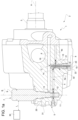
- numeral 2 indicates a power take-off, PTO, assembly of a work vehicle, in particular a specialty vehicle or an agricultural vehicle, such as a tractor or an earth moving machine.
- PTO assembly 2 comprises a powertrain with an output shaft 3, which is rotatable about a longitudinal axis A and is installed on the work vehicle in a position that allows it to power external implements by means of mating fittings.
- PTO assembly 2 further comprises a clutch configured to selectively couple output shaft 3 to a mechanical power source of the work vehicle, and a brake configured to impart a braking torque to output shaft 3.
- the mechanical power source is, for example, a combustion engine and/or one or more electric motors of the work vehicle that may be coupled to the transmission e.g. to an input shaft 31.
- input shaft 31 is parallel to longitudinal axis A of output shaft 3.
- PTO assembly 2 comprises a hydraulic arrangement 1 for controlling the operation of the clutch and the brake.
- the hydraulic arrangement 1 comprises, in turn, a brake line 4 fluidly connecting a source 5 of fluid in pressure of the work vehicle to the brake and a clutch line 6 fluidly connecting the source 5 to the clutch.
- the fluid in pressure is a fluid suitable for actuating both the brake and the clutch, such as a mineral oil.
- the brake can be set in a braked configuration, in which it imparts, in use, the braking torque to output shaft 3, so as to prevent output shaft 3 from freely rotating about longitudinal axis A or in an unbraked configuration, in which it allows, in use, output shaft 3 to freely rotate about longitudinal axis A.
- the brake is set by default in the braked configuration, for safety reasons, so as to prevent output shaft 3 from undesirably rotating about longitudinal axis A.
- the hydraulic arrangement 1 further comprises first valve means 7 configured to control the flow of fluid between source 5, brake line 4 and clutch line 6; and second valve means 8 configured to control the flow of fluid between source 5 and the brake.
- first valve means 7 comprise an electro-actuated valve 9 and second valve means 8 comprise a hydraulic-actuated valve 10.
- the hydraulic-actuated valve 10 is controlled as a function of a pressure p0 of the fluid inside clutch line 6.
- PTO assembly 2 comprises a control unit 30, which is operatively connected to electro-actuated valve 9.
- Hydraulic arrangement 1 can be set in a first configuration, which is illustrated in figures 1 and 1a , in which first valve means 7 allow a fluidic connection between source 5 and brake line 4 and second valve means 8 allow a fluidic connection between source 5 and the brake. Hydraulic arrangement 1 can be further set in a second configuration, which is illustrated in figures 2 and 2a , in which first valve means 7 allow a fluidic connection of both brake and clutch lines 4, 6 with source 5 and second valve means 8 deny the fluidic connection between source 5 and the brake.
- the brake is set in the braked configuration or in the unbraked configuration when, in use, hydraulic arrangement 1 is respectively in the first or in the second configuration.
- the clutch is activated - i.e. it connects, in use, output shaft 3 to input shaft 31 - if a pressure p0 of the fluid in clutch line 6 is equal to or greater than a clutch engagement pressure p2.
- electro-actuated valve 9 can be a three ways-two positions valve.
- electro-actuated valve 9 comprises a spool 20 configured to move in a respective seat of PTO assembly 2 along an axis B to close or open, totally or partially, a first, a second and a third opening 11, 12, 13.
- openings 11, 12, 13 are realized in the body of PTO assembly 2 and, furthermore, first opening 11 is fluidly connected to source 5, second opening 12 is fluidly connected to brake line 4 and third opening 13 is fluidly connected to clutch line 6.
- electro-actuated valve 9 is a proportional valve; therefore, the pressure of the fluid in clutch and brake lines 4, 6 can be varied depending on whether spool 20 partially or completely opens second and third openings 12, 13, respectively.
- Spool 20 can be set in a first position (shown in figures 1 and 1a ), in which first valve means 7 allow a fluidic connection between source 5 and brake line 4 through second opening 12, in a second position (shown in figures 2 and 2a ), in which first valve means 7 allow a fluidic connection between source 5 and brake line 4 through second opening 12 and between source 5 and clutch line 6 through third opening 13, or in a plurality of intermediate positions between the latter first and second positions.
- spool 20 in the second position totally opens the passage through third opening 13.
- first valve means 7 deny the fluidic connection between source 5 and clutch line 6 when, in use, spool 20 is in the first position.
- Control unit 30 is configured to control the position of spool 20 of electro-actuated valve 9 between the first and the second position by sending to such valve an appropriate electric signal I C .
- first valve means 7 are controlled to constantly allow the fluidic connection between source 5 and brake line 4. Furthermore, spool 20 constantly completely opens first and second openings 11, 12.
- control unit 30 is configured to control electro-actuated valve 9 so as to vary the extent to which third opening 13 is opened by spool 20.
- second valve means 8 are fluidly interposed in brake line 4, thereby defining a first brake line portion 4a and a second brake line portion 4b.
- hydraulic-actuated valve 10 is a three ways-two positions valve and more preferably a proportional valve.
- hydraulic-actuated valve 10 comprises a spool 21 configured to move in a respective seat of PTO assembly 2 along an axis C and configured to partially and/or totally open/close a fourth and a fifth opening 14, 15.
- openings 14 and 15 are realized in the body of PTO assembly 2 and, furthermore, fourth opening 14 is fluidly connected to first brake line portion 4a and fifth opening 15 is fluidly connected to second brake line portion 4b.
- Spool 21 can be set in a first position ( figures 1 and 1a ), in which second valve means 8 allow a fluidic connection between first brake line portion 4a and second brake line portion 4b, in a second position ( figures 2 and 2a ), in which second valve means 8 deny a fluidic connection between first brake line portion 4a and second brake line portion 4b, and in a plurality of intermediate positions between the latter first and second positions.
- Hydraulic arrangement 1 further comprises a discharge 32, which is configured to discharge the fluid in second brake line portion 4b when, in use, spool 21 is in the second position.
- second valve means 8 allow a fluidic connection between second brake line portion 4b and discharge 32.
- Spool 21 is actuated by means of a hydraulic pilot signal, which is spilled from clutch line 6.
- a hydraulic pilot signal is proportional to pressure p0 of the fluid in clutch line 6.
- clutch line 6 defines an opening 16, which is in fluidic communication with spool 21, so as allow the hydraulic pilot signal to be spilled from clutch line 6 through opening 16.
- the fluid in clutch line 6 exerts, in use, a force F 1 on spool 21 through opening 16.
- Force F 1 depends on pressure p0 of the fluid in clutch line 6, in particular, it is directly proportional to pressure p0.
- second valve means 8 comprise elastic means 22, which are adapted to bias spool 21 towards its first position.
- elastic means 22 comprise a helical spring 23.
- Elastic means 22 exert, in use, a force F 2 on spool 21, which is directed opposite to force F 1 .
- second valve means 8 are configured to be set in the second position when, in use, the pressure p0 of the fluid in clutch line 6 is equal to or greater than a brake disengagement pressure p1.
- brake disengagement pressure p1 is proportional to the minimum force F 1 that is sufficient to move spool 21 against force F 2 in the second position.
- clutch engagement pressure p2 is greater than brake disengagement pressure p1. Therefore, when pressure p0 is equal to or greater than brake disengagement pressure p1, but lower than clutch engagement pressure p2, the brake can be unbraked, without causing the activation of the clutch.
- spool 20 in the third position, which is intermediate between the first and the second positions of spool 20, spool 20 is configured to partially open opening 13 in such a manner that pressure p0 is equal to or greater than brake disengagement pressure p1, but lower than clutch engagement pressure p2.
- spool 20 In the fourth position, which is intermediate between the third position and the second position of spool 20, spool 20 is configured to partially open opening 13 in such a manner that pressure p0 is equal to or greater than clutch engagement pressure p2.
- Control unit 30 is configured to control spool 20 in the third or fourth position by modulating the electric signal I C .
- output shaft 3 is freely rotatable about longitudinal axis A.
- brake disengagement pressure p1 is approximately equal to 0.5 bar and clutch engagement pressure p2 is approximately equal to 1,5 bar.
- hydraulic arrangement 1 according to the invention and described as above is illustrated starting from the condition shown in figures 1 and 1a .
- hydraulic arrangement 1 is set in the first configuration, therefore first valve means 7 allow the fluidic connection between source 5 and brake line 4 and second valve means 8 allow the fluidic connection between source 5 and the brake.
- spools 20 and 21 are set in the respective first positions.
- control unit 30 controls electro-actuated valve 9 so as to set spool 20 in the third position. Accordingly, pressure p0 is set equal to or greater than brake disengagement pressure p1, but lower than clutch engagement pressure p2 and, therefore, force F 1 is set greater than force F 2 .
- spool 21 slides from its first position to its second position, in which it denies the fluidic connection between first and second brake line portions 4a, 4b.
- the fluid in second brake line portion 4b is then discharged through discharge 32.
- first valve means 7 allow the fluidic connection of both brake and clutch lines 4, 6 with source 5
- second valve means 8 deny the fluidic connection between source 5 and the brake and hydraulic configuration 1 is set in the second configuration.
- output shaft 3 can be freely rotated, e.g. manually rotated, about longitudinal axis A.
- control unit 30 controls electro-actuated valve 9 so as to set spool 20 in the fourth position or in the second position. Accordingly, pressure p0 is set equal to or greater than clutch engagement pressure p2. Consequently, force F 1 is set greater than force F 2 and spool 21 is moved to or kept at the second position. The fluid in second brake line portion 4b is then discharged through discharge 32.
- first valve means 7 allow the fluidic connection of both brake and clutch lines 4, 6 with source 5
- second valve means 8 deny the fluidic connection between source 5 and the brake and hydraulic configuration 1 is set in the second configuration.
- the clutch is activated, the brake is unbraked and external implements can be powered by output shaft 3.
- the invention also relates to a method for controlling PTO assembly 2, comprising the steps of:
- the aforementioned method can be performed by the electronic unit 30 that is provided with suitable elaboration means.
- hydraulic arrangement 1 comprises only one electro-actuated valve 9 and hydraulic-actuated valve 10 is controlled as a function of pressure p0 of the fluid in clutch line 6, the operation of the brake and the clutch of PTO assembly 2 can be controlled in a cost-effective and compact manner.
- hydraulic-actuated valve 10 is less bulky and expensive than an electro-actuated valve.
- brake disengagement pressure p1 is lower than clutch engagement pressure p2
- the brake can be set in the unbraked configuration without causing the activation of the clutch.
- output shaft 3 is freely rotatable about longitudinal axis A. This can be particularly advantageous, for example, when it is necessary to manually rotate output shaft 3.
- PTO assembly 2 may comprise more than one output shaft 3, more than one clutch and/or more than one brake.
Landscapes
- Engineering & Computer Science (AREA)
- General Engineering & Computer Science (AREA)
- Mechanical Engineering (AREA)
- Transportation (AREA)
- Physics & Mathematics (AREA)
- Fluid Mechanics (AREA)
- Chemical & Material Sciences (AREA)
- Combustion & Propulsion (AREA)
- Arrangement And Driving Of Transmission Devices (AREA)
- Auxiliary Drives, Propulsion Controls, And Safety Devices (AREA)
- Fluid-Pressure Circuits (AREA)
- Hydraulic Clutches, Magnetic Clutches, Fluid Clutches, And Fluid Joints (AREA)
Claims (11)
- Zapfwellen (PTO)-Anordnung (2) für ein Arbeitsfahrzeug, wobei die PTO-Anordnung (2) umfasst:- mindestens eine Ausgangswelle (3);- mindestens eine Kupplung, die dazu eingerichtet ist, die Ausgangswelle (3) wahlweise mit einer mechanischen Energiequelle des Arbeitsfahrzeugs zu koppeln; und- mindestens eine Bremse, die dazu eingerichtet ist, ein Bremsmoment auf die Ausgangswelle (3) auszuüben; und- eine Hydraulikanordnung (1) mit:- einer Bremsleitung (4), die eine Quelle (5) von unter Druck stehendem Fluid des Arbeitsfahrzeugs mit der mindestens einen Bremse fluidisch verbindet; und- einer Kupplungsleitung (6), die die Quelle (5) mit der mindestens einen Kupplung fluidisch verbindet;wobei die Hydraulikanordnung (1) des Weiteren umfasst:- eine erste Ventileinrichtung (7), die dazu eingerichtet ist, den Fluss an Fluid zwischen der Quelle (5), der Bremsleitung (4) und der Kupplungsleitung (6) zu steuern; und- eine zweite Ventileinrichtung (8), die dazu eingerichtet ist, den Fluss an Fluid zwischen der Quelle (5) und der mindestens einen Bremse zu steuern;wobei die erste Ventileinrichtung (7) ein elektrisch betätigtes Ventil (9) aufweist und die zweite Ventileinrichtung (8) ein hydraulisch betätigtes Ventil (10) aufweist; wobei das hydraulisch betätigte Ventil (10) in Abhängigkeit von dem Druck (p0) des Fluids innerhalb der Kupplungsleitung (6) gesteuert wird,wobei die Hydraulikanordnung (1) zumindest einstellbar ist in:- eine erste Konfiguration, in der die erste Ventileinrichtung (7) eine fluidische Verbindung zwischen der Quelle (5) und der Bremsleitung (4) ermöglicht und in der die zweite Ventileinrichtung (8) eine fluidische Verbindung zwischen der Quelle (5) und der mindestens einen Bremse ermöglicht; oder- eine zweite Konfiguration, in der die erste Ventileinrichtung (7) eine fluidische Verbindung sowohl der Bremsleitung als auch der Kupplungsleitung (4, 6) mit der Quelle (5) ermöglicht und in der die zweite Ventileinrichtung (8) eine fluidische Verbindung zwischen der Quelle (5) und der mindestens einen Bremse verhindert;wobei die PTO-Anordnung dadurch gekennzeichnet ist, dass sie des Weiteren definiert:- eine erste Öffnung (11), die fluidisch mit der Quelle (5) verbunden ist;- eine zweite Öffnung (12), die fluidisch mit der Bremsleitung (4) verbunden ist; und- eine dritte Öffnung (13), die fluidisch mit der Kupplungsleitung (6) verbunden ist;wobei die erste Ventileinrichtung (7) einen Kolben (20) aufweist, der zumindest einstellbar ist in:- eine erste Position, in der die erste Ventileinrichtung (7) eine fluidische Verbindung zwischen der Quelle (5) und der Bremsleitung (4) durch die zweite Öffnung (12) ermöglicht;- eine zweite Position, in der die erste Ventileinrichtung (7) eine fluidische Verbindung zwischen der Quelle (5) und der Bremsleitung (4) durch die zweite Öffnung (12) und zwischen der Quelle (5) und der Kupplungsleitung (6) durch die dritte Öffnung (13) ermöglicht.
- Zapfwellen-Anordnung nach einem der vorhergehenden Ansprüche, wobei die zweite Ventileinrichtung (8) fluidisch in die Bremsleitung (4) eingefügt ist, wodurch ein erster Bremsleitungsabschnitt (4a) und ein zweiter Bremsleitungsabschnitt (4b) der Bremsleitung (4) definiert ist;wobei die PTO-Anordnung (2) des Weiteren definiert:- eine vierte Öffnung (14), die fluidisch mit dem ersten Bremsleitungsabschnitt (4a) verbunden ist; und- eine fünfte Öffnung (15), die fluidisch mit dem zweiten Bremsleitungsabschnitt (4b) verbunden ist;wobei die zweite Ventileinrichtung (8) einen Kolben (21) aufweist, der zumindest einstellbar ist in:- eine erste Position, in der die zweite Ventileinrichtung (8) eine fluidische Verbindung zwischen dem ersten Bremsleitungsabschnitt (4a) und dem zweiten Bremsleitungsabschnitt (4b) durch die vierte bzw. die fünfte Öffnung (14, 15) ermöglicht; und- eine zweite Position, in der die zweite Ventileinrichtung (8) eine fluidische Verbindung zwischen dem ersten Bremsleitungsabschnitt (4a) und dem zweiten Bremsleitungsabschnitt (4b) verhindert.
- Zapfwellen-Anordnung nach Anspruch 2, wobei der Kolben (21) der zweiten Ventileinrichtung (8) mittels eines hydraulischen Pilotsignals betätigt wird, das von der Kupplungsleitung (6) ausströmt.
- Zapfwellen-Anordnung nach Anspruch 2 oder 3, wobei die zweite Ventileinrichtung (8) weiterhin elastische Mittel (22) aufweist, die dazu eingerichtet sind, den Kolben (21) in Richtung seiner ersten Position vorzuspannen.
- Zapfwellen-Anordnung nach Anspruch 4 in Abhängigkeit von Anspruch 3, wobei die Kupplungsleitung (6) eine weitere Öffnung (16) definiert, die in fluidischer Verbindung mit dem Kolben (21) der zweiten Ventileinrichtung (8) steht; wobei das hydraulische Pilotsignal von der Kupplungsleitung (6) durch die weitere Öffnung (16) strömt;wobei das Fluid in der Kupplungsleitung (6) im Betrieb eine erste Kraft (F1) auf den Kolben (22) der zweiten Ventileinrichtung (8) durch die weitere Öffnung (16) ausübt; wobei die erste Kraft (F1) abhängig von dem Druck (p0) des Fluids in der Kupplungsleitung (6) ist;wobei die elastischen Mittel (22) im Betrieb eine zweite Kraft (F2) auf den Kolben (21) der zweiten Ventileinrichtung (8) ausüben;wobei die erste Kraft (F1) entgegen der zweiten Kraft (F2) gerichtet ist.
- Zapfwellen-Anordnung nach Anspruch 5, wobei der Kolben (21) der zweiten Ventileinrichtung (8) dazu eingerichtet ist, in die zweite Position gestellt zu werden, wenn der Druck (p0) des Fluids in der Kupplungsleitung (6) im Betrieb gleich oder größer als ein Bremsenlösedruck (p1) ist;
wobei die erste Kraft (F1) größer als die zweite Kraft (F2) ist, wenn der Druck (p0) des Fluids in der Kupplungsleitung (6) im Betrieb gleich oder größer als der Bremsenlösedruck (p1) ist. - Zapfwellen-Anordnung nach Anspruch 6, wobei der Druck (p0) des Fluids in der Kupplungsleitung (6) gleich oder größer als ein Kupplungseinrückdruck (p2) ist;wobei der Kupplungseinrückdruck (p2) der Druck ist, bei dem im Betrieb die mindestens eine Kupplung betätigt wird;wobei der Bremsenlösedruck (p1) niedriger als der Kupplungseinrückdruck (p2) ist.
- Zapfwellen-Anordnung nach Anspruch 7, wobei die Ausgangswelle (3) eine Längsachse (A) definiert; wobei die Ausgangswelle (3) frei um die Längsachse (A) drehbar ist, wenn der Druck (p0) des Fluids in der Kupplungsleitung (6) im Betrieb gleich oder größer als der Bremsenlösedruck (p1) und niedriger als der Kupplungseinrückdruck (p2) ist.
- Zapfwellen-Anordnung nach einem der Ansprüche 6 bis 8, wobei der Bremsenlösedruck (p1) in etwa 0,5 bar beträgt.
- Zapfwellen-Anordnung nach einem der vorhergehenden Ansprüche, die des Weiteren eine Steuereinheit (30) aufweist, die dazu eingerichtet ist, das elektrisch betätigte Ventil (9) der Hydraulikanordnung (1) zu steuern.
- Verfahren zum Steuern einer Zapfwellen (PTO)-Anordnung (2) nach einem der vorhergehenden Ansprüche, wobei das Verfahren die Schritte aufweist:- Empfangen einer Aufforderung zum Lösen der Ausgangswelle (3) und zum Auskuppeln der mindestens einen Kupplung;- Bereitstellen eines Steuersignals (Ic) an das elektrisch betätigte Ventil (9), um den Druck (p0) des Fluids in der Kupplungsleitung (6) zu variieren, so dass der Druck (p0) des Fluids in der Kupplungsleitung (6) gleich oder größer als ein Bremsenlösedruck (p1), aber niedriger als ein Kupplungseinrückdruck (p2) ist;wobei der Bremsenlösedruck (p1) der Druck ist, bei dem die mindestens eine Bremse gelöst wird; wobei der Kupplungseinrückdruck (p2) der Druck ist, bei dem die mindestens eine Kupplung betätigt wird.
Applications Claiming Priority (1)
| Application Number | Priority Date | Filing Date | Title |
|---|---|---|---|
| IT102020000032174A IT202000032174A1 (it) | 2020-12-23 | 2020-12-23 | Assieme di presa di potenza per veicolo da lavoro comprendente una disposizione idraulica ed un relativo metodo di controllo |
Publications (2)
| Publication Number | Publication Date |
|---|---|
| EP4019795A1 EP4019795A1 (de) | 2022-06-29 |
| EP4019795B1 true EP4019795B1 (de) | 2024-07-31 |
Family
ID=74858685
Family Applications (1)
| Application Number | Title | Priority Date | Filing Date |
|---|---|---|---|
| EP21215246.6A Active EP4019795B1 (de) | 2020-12-23 | 2021-12-16 | Zapfwellenanordnung für ein arbeitsfahrzeug mit einer hydraulischen anordnung und entsprechendes steuerverfahren |
Country Status (2)
| Country | Link |
|---|---|
| EP (1) | EP4019795B1 (de) |
| IT (1) | IT202000032174A1 (de) |
Families Citing this family (2)
| Publication number | Priority date | Publication date | Assignee | Title |
|---|---|---|---|---|
| IT202100014051A1 (it) * | 2021-05-28 | 2022-11-28 | Cnh Ind Italia Spa | Assieme di presa di potenza per un veicolo di lavoro comprendente una disposizione di lubrificazione migliorata |
| EP4407206B1 (de) * | 2023-01-27 | 2025-09-24 | CNH Industrial Italia S.p.A. | Verbessertes verfahren und vorrichtung zur steuerung einer zapfwellenanordnung eines arbeitsfahrzeugs |
Family Cites Families (2)
| Publication number | Priority date | Publication date | Assignee | Title |
|---|---|---|---|---|
| JP4902075B2 (ja) * | 2001-09-25 | 2012-03-21 | ヤンマー株式会社 | 作業車の動力取出し装置 |
| JP2005263117A (ja) * | 2004-03-19 | 2005-09-29 | Yanmar Co Ltd | 作業車両の動力取出装置 |
-
2020
- 2020-12-23 IT IT102020000032174A patent/IT202000032174A1/it unknown
-
2021
- 2021-12-16 EP EP21215246.6A patent/EP4019795B1/de active Active
Also Published As
| Publication number | Publication date |
|---|---|
| IT202000032174A1 (it) | 2022-06-23 |
| EP4019795A1 (de) | 2022-06-29 |
Similar Documents
| Publication | Publication Date | Title |
|---|---|---|
| EP4019795B1 (de) | Zapfwellenanordnung für ein arbeitsfahrzeug mit einer hydraulischen anordnung und entsprechendes steuerverfahren | |
| CN107636365B (zh) | 驻车制动系统 | |
| CA1037347A (en) | Regulating valve with hydraulic detent | |
| JPH063228B2 (ja) | クラツチ潤滑の制御装置 | |
| US6467262B1 (en) | Emergency hydraulic control for a clutch arranged between an internal combustion engine and a gear box | |
| JPS604390B2 (ja) | 動力伝動装置 | |
| US4469011A (en) | Pressure control device for the actuation of a clutch or brake | |
| US6450309B1 (en) | Transmission system structure of vehicle | |
| US4567971A (en) | Hydraulic circuit for activating a clutch and a throttle valve used in the circuit | |
| GB2284026A (en) | Electro-hydraulic interlock system for a transmission maintains a ratio clutch engaged on supply failure | |
| EP0928375A1 (de) | Automatisch gesteuerte kupplung | |
| US6659899B2 (en) | Electrohydraulic control system for controlling gearspeed changes in partially or fully automatic transmissions of vehicles | |
| US3991787A (en) | Modulation control valve for hydraulically operated winch | |
| US5072814A (en) | Hydraulically operable transmission | |
| EP3760503B1 (de) | Verbesserte hydraulische bremsanordnung für ein geländefahrzeug | |
| US6432016B1 (en) | Driving device | |
| EP4095417B1 (de) | Zapfwellenanordnung eines arbeitsfahrzeugs mit verbesserter schmiervorrichtung | |
| US5288140A (en) | Parking brake controller with slower actuation in the event of a malfunction | |
| GB2343929A (en) | Hydraulic clutch actuation system with electrically operated valve | |
| EP0057539A1 (de) | Kupplungsregulierungssystem | |
| KR100342232B1 (ko) | 구동장치 | |
| US8771120B2 (en) | Control system for electronic range selection in a dual clutch transmission and for a differential in a transmission | |
| EP3527443A1 (de) | Hydraulisches steuerungssystem | |
| CA1100846A (en) | Multi-function steering and brake control valve | |
| US7861837B2 (en) | Hydraulic clutch actuation system |
Legal Events
| Date | Code | Title | Description |
|---|---|---|---|
| PUAI | Public reference made under article 153(3) epc to a published international application that has entered the european phase |
Free format text: ORIGINAL CODE: 0009012 |
|
| STAA | Information on the status of an ep patent application or granted ep patent |
Free format text: STATUS: THE APPLICATION HAS BEEN PUBLISHED |
|
| AK | Designated contracting states |
Kind code of ref document: A1 Designated state(s): AL AT BE BG CH CY CZ DE DK EE ES FI FR GB GR HR HU IE IS IT LI LT LU LV MC MK MT NL NO PL PT RO RS SE SI SK SM TR |
|
| STAA | Information on the status of an ep patent application or granted ep patent |
Free format text: STATUS: REQUEST FOR EXAMINATION WAS MADE |
|
| 17P | Request for examination filed |
Effective date: 20230102 |
|
| RBV | Designated contracting states (corrected) |
Designated state(s): AL AT BE BG CH CY CZ DE DK EE ES FI FR GB GR HR HU IE IS IT LI LT LU LV MC MK MT NL NO PL PT RO RS SE SI SK SM TR |
|
| RAP3 | Party data changed (applicant data changed or rights of an application transferred) |
Owner name: CNH INDUSTRIAL ITALIA S.P.A. |
|
| RIC1 | Information provided on ipc code assigned before grant |
Ipc: F16D 67/04 20060101ALI20230905BHEP Ipc: F16D 48/02 20060101AFI20230905BHEP |
|
| GRAP | Despatch of communication of intention to grant a patent |
Free format text: ORIGINAL CODE: EPIDOSNIGR1 |
|
| STAA | Information on the status of an ep patent application or granted ep patent |
Free format text: STATUS: GRANT OF PATENT IS INTENDED |
|
| INTG | Intention to grant announced |
Effective date: 20231123 |
|
| GRAJ | Information related to disapproval of communication of intention to grant by the applicant or resumption of examination proceedings by the epo deleted |
Free format text: ORIGINAL CODE: EPIDOSDIGR1 |
|
| STAA | Information on the status of an ep patent application or granted ep patent |
Free format text: STATUS: REQUEST FOR EXAMINATION WAS MADE |
|
| GRAP | Despatch of communication of intention to grant a patent |
Free format text: ORIGINAL CODE: EPIDOSNIGR1 |
|
| STAA | Information on the status of an ep patent application or granted ep patent |
Free format text: STATUS: GRANT OF PATENT IS INTENDED |
|
| INTC | Intention to grant announced (deleted) | ||
| INTG | Intention to grant announced |
Effective date: 20240429 |
|
| GRAS | Grant fee paid |
Free format text: ORIGINAL CODE: EPIDOSNIGR3 |
|
| GRAA | (expected) grant |
Free format text: ORIGINAL CODE: 0009210 |
|
| STAA | Information on the status of an ep patent application or granted ep patent |
Free format text: STATUS: THE PATENT HAS BEEN GRANTED |
|
| AK | Designated contracting states |
Kind code of ref document: B1 Designated state(s): AL AT BE BG CH CY CZ DE DK EE ES FI FR GB GR HR HU IE IS IT LI LT LU LV MC MK MT NL NO PL PT RO RS SE SI SK SM TR |
|
| REG | Reference to a national code |
Ref country code: CH Ref legal event code: EP Ref country code: GB Ref legal event code: FG4D |
|
| REG | Reference to a national code |
Ref country code: DE Ref legal event code: R096 Ref document number: 602021016439 Country of ref document: DE |
|
| REG | Reference to a national code |
Ref country code: IE Ref legal event code: FG4D |
|
| REG | Reference to a national code |
Ref country code: LT Ref legal event code: MG9D |
|
| REG | Reference to a national code |
Ref country code: NL Ref legal event code: MP Effective date: 20240731 |
|
| PG25 | Lapsed in a contracting state [announced via postgrant information from national office to epo] |
Ref country code: PT Free format text: LAPSE BECAUSE OF FAILURE TO SUBMIT A TRANSLATION OF THE DESCRIPTION OR TO PAY THE FEE WITHIN THE PRESCRIBED TIME-LIMIT Effective date: 20241202 |
|
| REG | Reference to a national code |
Ref country code: AT Ref legal event code: MK05 Ref document number: 1708709 Country of ref document: AT Kind code of ref document: T Effective date: 20240731 |
|
| PG25 | Lapsed in a contracting state [announced via postgrant information from national office to epo] |
Ref country code: PT Free format text: LAPSE BECAUSE OF FAILURE TO SUBMIT A TRANSLATION OF THE DESCRIPTION OR TO PAY THE FEE WITHIN THE PRESCRIBED TIME-LIMIT Effective date: 20241202 |
|
| PG25 | Lapsed in a contracting state [announced via postgrant information from national office to epo] |
Ref country code: NO Free format text: LAPSE BECAUSE OF FAILURE TO SUBMIT A TRANSLATION OF THE DESCRIPTION OR TO PAY THE FEE WITHIN THE PRESCRIBED TIME-LIMIT Effective date: 20241031 |
|
| PG25 | Lapsed in a contracting state [announced via postgrant information from national office to epo] |
Ref country code: NL Free format text: LAPSE BECAUSE OF FAILURE TO SUBMIT A TRANSLATION OF THE DESCRIPTION OR TO PAY THE FEE WITHIN THE PRESCRIBED TIME-LIMIT Effective date: 20240731 Ref country code: PL Free format text: LAPSE BECAUSE OF FAILURE TO SUBMIT A TRANSLATION OF THE DESCRIPTION OR TO PAY THE FEE WITHIN THE PRESCRIBED TIME-LIMIT Effective date: 20240731 Ref country code: GR Free format text: LAPSE BECAUSE OF FAILURE TO SUBMIT A TRANSLATION OF THE DESCRIPTION OR TO PAY THE FEE WITHIN THE PRESCRIBED TIME-LIMIT Effective date: 20241101 Ref country code: FI Free format text: LAPSE BECAUSE OF FAILURE TO SUBMIT A TRANSLATION OF THE DESCRIPTION OR TO PAY THE FEE WITHIN THE PRESCRIBED TIME-LIMIT Effective date: 20240731 |
|
| PG25 | Lapsed in a contracting state [announced via postgrant information from national office to epo] |
Ref country code: BG Free format text: LAPSE BECAUSE OF FAILURE TO SUBMIT A TRANSLATION OF THE DESCRIPTION OR TO PAY THE FEE WITHIN THE PRESCRIBED TIME-LIMIT Effective date: 20240731 |
|
| PG25 | Lapsed in a contracting state [announced via postgrant information from national office to epo] |
Ref country code: LV Free format text: LAPSE BECAUSE OF FAILURE TO SUBMIT A TRANSLATION OF THE DESCRIPTION OR TO PAY THE FEE WITHIN THE PRESCRIBED TIME-LIMIT Effective date: 20240731 |
|
| PG25 | Lapsed in a contracting state [announced via postgrant information from national office to epo] |
Ref country code: IS Free format text: LAPSE BECAUSE OF FAILURE TO SUBMIT A TRANSLATION OF THE DESCRIPTION OR TO PAY THE FEE WITHIN THE PRESCRIBED TIME-LIMIT Effective date: 20241130 Ref country code: AT Free format text: LAPSE BECAUSE OF FAILURE TO SUBMIT A TRANSLATION OF THE DESCRIPTION OR TO PAY THE FEE WITHIN THE PRESCRIBED TIME-LIMIT Effective date: 20240731 |
|
| PG25 | Lapsed in a contracting state [announced via postgrant information from national office to epo] |
Ref country code: HR Free format text: LAPSE BECAUSE OF FAILURE TO SUBMIT A TRANSLATION OF THE DESCRIPTION OR TO PAY THE FEE WITHIN THE PRESCRIBED TIME-LIMIT Effective date: 20240731 |
|
| PG25 | Lapsed in a contracting state [announced via postgrant information from national office to epo] |
Ref country code: ES Free format text: LAPSE BECAUSE OF FAILURE TO SUBMIT A TRANSLATION OF THE DESCRIPTION OR TO PAY THE FEE WITHIN THE PRESCRIBED TIME-LIMIT Effective date: 20240731 Ref country code: RS Free format text: LAPSE BECAUSE OF FAILURE TO SUBMIT A TRANSLATION OF THE DESCRIPTION OR TO PAY THE FEE WITHIN THE PRESCRIBED TIME-LIMIT Effective date: 20241031 |
|
| PG25 | Lapsed in a contracting state [announced via postgrant information from national office to epo] |
Ref country code: RS Free format text: LAPSE BECAUSE OF FAILURE TO SUBMIT A TRANSLATION OF THE DESCRIPTION OR TO PAY THE FEE WITHIN THE PRESCRIBED TIME-LIMIT Effective date: 20241031 Ref country code: PL Free format text: LAPSE BECAUSE OF FAILURE TO SUBMIT A TRANSLATION OF THE DESCRIPTION OR TO PAY THE FEE WITHIN THE PRESCRIBED TIME-LIMIT Effective date: 20240731 Ref country code: NO Free format text: LAPSE BECAUSE OF FAILURE TO SUBMIT A TRANSLATION OF THE DESCRIPTION OR TO PAY THE FEE WITHIN THE PRESCRIBED TIME-LIMIT Effective date: 20241031 Ref country code: NL Free format text: LAPSE BECAUSE OF FAILURE TO SUBMIT A TRANSLATION OF THE DESCRIPTION OR TO PAY THE FEE WITHIN THE PRESCRIBED TIME-LIMIT Effective date: 20240731 Ref country code: LV Free format text: LAPSE BECAUSE OF FAILURE TO SUBMIT A TRANSLATION OF THE DESCRIPTION OR TO PAY THE FEE WITHIN THE PRESCRIBED TIME-LIMIT Effective date: 20240731 Ref country code: IS Free format text: LAPSE BECAUSE OF FAILURE TO SUBMIT A TRANSLATION OF THE DESCRIPTION OR TO PAY THE FEE WITHIN THE PRESCRIBED TIME-LIMIT Effective date: 20241130 Ref country code: HR Free format text: LAPSE BECAUSE OF FAILURE TO SUBMIT A TRANSLATION OF THE DESCRIPTION OR TO PAY THE FEE WITHIN THE PRESCRIBED TIME-LIMIT Effective date: 20240731 Ref country code: GR Free format text: LAPSE BECAUSE OF FAILURE TO SUBMIT A TRANSLATION OF THE DESCRIPTION OR TO PAY THE FEE WITHIN THE PRESCRIBED TIME-LIMIT Effective date: 20241101 Ref country code: FI Free format text: LAPSE BECAUSE OF FAILURE TO SUBMIT A TRANSLATION OF THE DESCRIPTION OR TO PAY THE FEE WITHIN THE PRESCRIBED TIME-LIMIT Effective date: 20240731 Ref country code: ES Free format text: LAPSE BECAUSE OF FAILURE TO SUBMIT A TRANSLATION OF THE DESCRIPTION OR TO PAY THE FEE WITHIN THE PRESCRIBED TIME-LIMIT Effective date: 20240731 Ref country code: BG Free format text: LAPSE BECAUSE OF FAILURE TO SUBMIT A TRANSLATION OF THE DESCRIPTION OR TO PAY THE FEE WITHIN THE PRESCRIBED TIME-LIMIT Effective date: 20240731 Ref country code: AT Free format text: LAPSE BECAUSE OF FAILURE TO SUBMIT A TRANSLATION OF THE DESCRIPTION OR TO PAY THE FEE WITHIN THE PRESCRIBED TIME-LIMIT Effective date: 20240731 |
|
| PGFP | Annual fee paid to national office [announced via postgrant information from national office to epo] |
Ref country code: DE Payment date: 20241227 Year of fee payment: 4 |
|
| PG25 | Lapsed in a contracting state [announced via postgrant information from national office to epo] |
Ref country code: RO Free format text: LAPSE BECAUSE OF FAILURE TO SUBMIT A TRANSLATION OF THE DESCRIPTION OR TO PAY THE FEE WITHIN THE PRESCRIBED TIME-LIMIT Effective date: 20240731 Ref country code: DK Free format text: LAPSE BECAUSE OF FAILURE TO SUBMIT A TRANSLATION OF THE DESCRIPTION OR TO PAY THE FEE WITHIN THE PRESCRIBED TIME-LIMIT Effective date: 20240731 Ref country code: SM Free format text: LAPSE BECAUSE OF FAILURE TO SUBMIT A TRANSLATION OF THE DESCRIPTION OR TO PAY THE FEE WITHIN THE PRESCRIBED TIME-LIMIT Effective date: 20240731 |
|
| PG25 | Lapsed in a contracting state [announced via postgrant information from national office to epo] |
Ref country code: EE Free format text: LAPSE BECAUSE OF FAILURE TO SUBMIT A TRANSLATION OF THE DESCRIPTION OR TO PAY THE FEE WITHIN THE PRESCRIBED TIME-LIMIT Effective date: 20240731 |
|
| PG25 | Lapsed in a contracting state [announced via postgrant information from national office to epo] |
Ref country code: CZ Free format text: LAPSE BECAUSE OF FAILURE TO SUBMIT A TRANSLATION OF THE DESCRIPTION OR TO PAY THE FEE WITHIN THE PRESCRIBED TIME-LIMIT Effective date: 20240731 |
|
| PG25 | Lapsed in a contracting state [announced via postgrant information from national office to epo] |
Ref country code: SK Free format text: LAPSE BECAUSE OF FAILURE TO SUBMIT A TRANSLATION OF THE DESCRIPTION OR TO PAY THE FEE WITHIN THE PRESCRIBED TIME-LIMIT Effective date: 20240731 |
|
| REG | Reference to a national code |
Ref country code: DE Ref legal event code: R097 Ref document number: 602021016439 Country of ref document: DE |
|
| PLBE | No opposition filed within time limit |
Free format text: ORIGINAL CODE: 0009261 |
|
| STAA | Information on the status of an ep patent application or granted ep patent |
Free format text: STATUS: NO OPPOSITION FILED WITHIN TIME LIMIT |
|
| PG25 | Lapsed in a contracting state [announced via postgrant information from national office to epo] |
Ref country code: MC Free format text: LAPSE BECAUSE OF FAILURE TO SUBMIT A TRANSLATION OF THE DESCRIPTION OR TO PAY THE FEE WITHIN THE PRESCRIBED TIME-LIMIT Effective date: 20240731 |
|
| 26N | No opposition filed |
Effective date: 20250501 |
|
| REG | Reference to a national code |
Ref country code: CH Ref legal event code: PL |
|
| PG25 | Lapsed in a contracting state [announced via postgrant information from national office to epo] |
Ref country code: LU Free format text: LAPSE BECAUSE OF NON-PAYMENT OF DUE FEES Effective date: 20241216 |
|
| PG25 | Lapsed in a contracting state [announced via postgrant information from national office to epo] |
Ref country code: SE Free format text: LAPSE BECAUSE OF FAILURE TO SUBMIT A TRANSLATION OF THE DESCRIPTION OR TO PAY THE FEE WITHIN THE PRESCRIBED TIME-LIMIT Effective date: 20240731 |
|
| REG | Reference to a national code |
Ref country code: BE Ref legal event code: MM Effective date: 20241231 |
|
| PG25 | Lapsed in a contracting state [announced via postgrant information from national office to epo] |
Ref country code: BE Free format text: LAPSE BECAUSE OF NON-PAYMENT OF DUE FEES Effective date: 20241231 |
|
| PG25 | Lapsed in a contracting state [announced via postgrant information from national office to epo] |
Ref country code: CH Free format text: LAPSE BECAUSE OF NON-PAYMENT OF DUE FEES Effective date: 20241231 |
|
| PG25 | Lapsed in a contracting state [announced via postgrant information from national office to epo] |
Ref country code: IE Free format text: LAPSE BECAUSE OF NON-PAYMENT OF DUE FEES Effective date: 20241216 |
|
| PGFP | Annual fee paid to national office [announced via postgrant information from national office to epo] |
Ref country code: GB Payment date: 20251223 Year of fee payment: 5 |
|
| PGFP | Annual fee paid to national office [announced via postgrant information from national office to epo] |
Ref country code: IT Payment date: 20251218 Year of fee payment: 5 |
|
| PGFP | Annual fee paid to national office [announced via postgrant information from national office to epo] |
Ref country code: FR Payment date: 20251223 Year of fee payment: 5 |